EP3219237B1 - Holding plate with improved closure element - Google Patents
Holding plate with improved closure element Download PDFInfo
- Publication number
- EP3219237B1 EP3219237B1 EP16160969.8A EP16160969A EP3219237B1 EP 3219237 B1 EP3219237 B1 EP 3219237B1 EP 16160969 A EP16160969 A EP 16160969A EP 3219237 B1 EP3219237 B1 EP 3219237B1
- Authority
- EP
- European Patent Office
- Prior art keywords
- elastic element
- holding plate
- closure flap
- cover
- base plate
- Prior art date
- Legal status (The legal status is an assumption and is not a legal conclusion. Google has not performed a legal analysis and makes no representation as to the accuracy of the status listed.)
- Active
Links
- 239000004745 nonwoven fabric Substances 0.000 claims description 22
- 229920001971 elastomer Polymers 0.000 claims description 13
- 239000000806 elastomer Substances 0.000 claims description 11
- 238000004519 manufacturing process Methods 0.000 claims description 6
- 239000000463 material Substances 0.000 description 15
- 239000000428 dust Substances 0.000 description 10
- 238000007789 sealing Methods 0.000 description 10
- 239000000243 solution Substances 0.000 description 8
- 238000003466 welding Methods 0.000 description 8
- 238000001746 injection moulding Methods 0.000 description 7
- 238000004026 adhesive bonding Methods 0.000 description 5
- 238000004049 embossing Methods 0.000 description 5
- 239000004033 plastic Substances 0.000 description 5
- 229920003023 plastic Polymers 0.000 description 5
- 229920001296 polysiloxane Polymers 0.000 description 4
- 229920002379 silicone rubber Polymers 0.000 description 4
- 229920002725 thermoplastic elastomer Polymers 0.000 description 4
- 239000004743 Polypropylene Substances 0.000 description 3
- 239000000835 fiber Substances 0.000 description 3
- 230000007246 mechanism Effects 0.000 description 3
- 239000012528 membrane Substances 0.000 description 3
- 238000000034 method Methods 0.000 description 3
- -1 polypropylene Polymers 0.000 description 3
- 229920001155 polypropylene Polymers 0.000 description 3
- 239000004944 Liquid Silicone Rubber Substances 0.000 description 2
- 230000008901 benefit Effects 0.000 description 2
- 239000000356 contaminant Substances 0.000 description 2
- 238000011109 contamination Methods 0.000 description 2
- 239000004744 fabric Substances 0.000 description 2
- 239000011888 foil Substances 0.000 description 2
- 230000001771 impaired effect Effects 0.000 description 2
- 239000012535 impurity Substances 0.000 description 2
- 238000002347 injection Methods 0.000 description 2
- 239000007924 injection Substances 0.000 description 2
- 239000007788 liquid Substances 0.000 description 2
- 239000002985 plastic film Substances 0.000 description 2
- 229920006255 plastic film Polymers 0.000 description 2
- 230000009467 reduction Effects 0.000 description 2
- 239000005060 rubber Substances 0.000 description 2
- 239000007787 solid Substances 0.000 description 2
- 229910000831 Steel Inorganic materials 0.000 description 1
- 230000009471 action Effects 0.000 description 1
- 239000000853 adhesive Substances 0.000 description 1
- 230000002411 adverse Effects 0.000 description 1
- 230000001419 dependent effect Effects 0.000 description 1
- 230000008021 deposition Effects 0.000 description 1
- 238000011161 development Methods 0.000 description 1
- 230000018109 developmental process Effects 0.000 description 1
- 230000000694 effects Effects 0.000 description 1
- 238000005304 joining Methods 0.000 description 1
- 230000000873 masking effect Effects 0.000 description 1
- 239000004750 melt-blown nonwoven Substances 0.000 description 1
- 239000002184 metal Substances 0.000 description 1
- 239000006223 plastic coating Substances 0.000 description 1
- 229920000728 polyester Polymers 0.000 description 1
- 238000007711 solidification Methods 0.000 description 1
- 230000008023 solidification Effects 0.000 description 1
- 239000010959 steel Substances 0.000 description 1
- 238000003860 storage Methods 0.000 description 1
Images


Classifications
-
- A—HUMAN NECESSITIES
- A47—FURNITURE; DOMESTIC ARTICLES OR APPLIANCES; COFFEE MILLS; SPICE MILLS; SUCTION CLEANERS IN GENERAL
- A47L—DOMESTIC WASHING OR CLEANING; SUCTION CLEANERS IN GENERAL
- A47L9/00—Details or accessories of suction cleaners, e.g. mechanical means for controlling the suction or for effecting pulsating action; Storing devices specially adapted to suction cleaners or parts thereof; Carrying-vehicles specially adapted for suction cleaners
- A47L9/10—Filters; Dust separators; Dust removal; Automatic exchange of filters
- A47L9/14—Bags or the like; Rigid filtering receptacles; Attachment of, or closures for, bags or receptacles
- A47L9/1427—Means for mounting or attaching bags or filtering receptacles in suction cleaners; Adapters
- A47L9/1436—Connecting plates, e.g. collars, end closures
- A47L9/1445—Connecting plates, e.g. collars, end closures with closure means
- A47L9/1454—Self-sealing closures, e.g. valves
Landscapes
- Engineering & Computer Science (AREA)
- Mechanical Engineering (AREA)
- Filters For Electric Vacuum Cleaners (AREA)
Description
Die Erfindung betrifft eine Halteplatte für einen Staubsaugerfilterbeutel, insbesondere zum Anordnen des Staubsaugerfilterbeutels in einem Staubsaugergehäuse.The invention relates to a holding plate for a vacuum cleaner filter bag, in particular for arranging the vacuum cleaner filter bag in a vacuum cleaner housing.
Derartige Halteplatten sind in vielfältiger Form bekannt. Viele bekannte Halteplatten weisen auch Verschlussvorrichtungen auf, damit die Durchtrittsöffnung in den Beutel nach Gebrauch des Beutels verschlossen werden kann, um ein ungewolltes Austreten des Sauggutes zu verhindern. Für den Verschlussmechanismus wurden unterschiedliche Lösungen vorgeschlagen, beispielsweise Schieberlösungen wie in der
Bei Lösungen mit sogenannten Verschlussklappen finden häufig Federelemente Verwendung, welche die Verschlussklappen nach Gebrauch in die Schließstellung drücken oder ziehen. Verwendung finden dabei beispielsweise Blattfedern wie in der
Häufig sind die Federelemente dabei im Filterbeutel angeordnet, wie in der
Die Dokumente
Die Lösungen mit automatischem Verschlussmechanismus haben sich als störanfällig erwiesen, insbesondere wenn sich diese im Staubraum, also innerhalb des Filterbeutels befinden. Die Verschlussfunktion ist im Betrieb nicht immer sichergestellt. Häufig bleibt die Verschlussklappe teilweise geöffnet.The solutions with automatic locking mechanism have proven to be prone to failure, especially if they are in the dust chamber, ie within the filter bag. The shutter function is not always ensured during operation. Often the flap remains partially open.
Aufgabe der Erfindung ist es daher, eine Halteplatte bereitzustellen, welche eine funktionssichere Lösung zum Verschließen der Durchtrittsöffnung aufweist, die auch in Großserie kostengünstig realisierbar ist.The object of the invention is therefore to provide a holding plate which has a functionally reliable solution for closing the passage opening, which is inexpensive to realize even in mass production.
Diese Aufgabe wird durch eine Halteplatte gemäß Anspruch 1 gelöst. Besonders vorteilhafte Weiterbildungen finden sich in den Unteransprüchen.This object is achieved by a holding plate according to claim 1. Particularly advantageous developments can be found in the dependent claims.
Die Erfinder der vorliegenden Anmeldung haben erkannt, dass Probleme in Bezug auf die Verschlussfunktion bei bekannten Halteplatten häufig der Tatsache zuzuordnen sind, dass sich Staub oder andere Fremdkörper im Bereich der Federelemente anlagern, so dass diese die Verschlussklappe nur mehr unzureichend mit der erforderlichen Federkraft beaufschlagen können. Die vorliegende Erfindung verhindert oder reduziert die Ablagerung von solchen Störelementen dadurch, dass das elastische Element mittels des Abdeckelements wenigstens teilweise abgedeckt und damit gegenüber der Umgebung abgeschirmt wird. Im Betrieb gelangen daher keine oder weniger Verunreinigungen in Bereiche der Feder, in denen solche Verunreinigungen die Funktion des elastischen Elements negativ beeinflussen könnten. Die Funktionssicherheit des Verschlussmechanismus wird dadurch verbessert. Die Lösung ist ebenfalls einfach realisierbar, so dass sie auch kostengünstig in Großserie umgesetzt werden kann.The inventors of the present application have recognized that problems with regard to the closure function in known holding plates are often attributable to the fact that dust or other foreign bodies settle in the area of the spring elements, so that they can only insufficiently apply the necessary spring force to the closing flap , The present invention prevents or reduces the deposition of such interference elements in that the elastic element is at least partially covered by the cover element and thus shielded from the environment. In operation, therefore, no or less contaminants enter areas of the spring where such contaminants could adversely affect the function of the elastic element. The reliability of the closure mechanism is thereby improved. The solution is also easy to implement, so that it can be implemented cost-effectively in mass production.
Über das elastische Element wird die Verschlussklappe in Verschlussstellung vorgespannt. Das bedeutet, dass zum Öffnen der Verschlussklappe eine Kraft aufgewendet werden muss. Diese Kraft kann durch einen Stutzen des Staubsaugers und/oder den in den Beutel einströmenden Luftstrom ausgeübt werden. Wenn sich die Verschlussklappe in geöffneter Position befindet, wird sie über das elastische Element in Schließrichtung mit einer Kraft beaufschlagt. Diese Kraft führt nach Wegfall der in Öffnungsrichtung wirkenden Kraft dazu, dass die Verschlussklappe in die Verschlussstellung zurückkehrt.About the elastic element, the closure flap is biased in the closed position. This means that a force must be used to open the flap. This force can be exerted by a neck of the vacuum cleaner and / or the air flow flowing into the bag. When the flap is in the open position, it is acted upon by the elastic element in the closing direction with a force. After eliminating the force acting in the opening direction, this force causes the closure flap to return to the closed position.
Die Verschlussklappe kann über ein Gelenk, insbesondere ein Filmscharnier, mit Teilen der Halteplatte, insbesondere der Grundplatte, verbunden sein. Die Verschlussklappe kann eine Form aufweisen, die der Form der Durchtrittsöffnung entspricht.The closure flap can be connected via a joint, in particular a film hinge, with parts of the holding plate, in particular the base plate. The closure flap may have a shape that corresponds to the shape of the passage opening.
Als "Abdecken" wird hierin ein Abschirmen gegenüber der Umgebung verstanden. Mit anderen Worten trennt das Abdeckelement das elastische Element teilweise oder vollständig von der Umgebung. Mit anderen Worten überlappt das Abdeckelement das elastische Element wenigstens teilweise bei Draufsicht auf die Halteplatte auf die Seite, an der das elastische Element angeordnet ist. Durch das Abdeckelement wird also eine Seite des elastischen Elements abgedeckt, die von dem Teil der Halteplatte, an dem das elastische Element angeordnet ist, weg weist.By "masking" is meant herein shielding from the environment. In other words, the cover element separates the elastic element partially or completely from the environment. In other words, the cover element overlaps the elastic element at least partially in plan view of the holding plate on the side on which the elastic element is arranged. By the cover so one side of the elastic member is covered, which points away from the part of the holding plate on which the elastic member is arranged.
Das Abdeckelement kann vom elastischen Element beabstandet sein. In diesem Fall überlappt das Abdeckelement das elastische Element, ohne es zu berühren. Es ist aber auch möglich, dass das Abdeckelement das elastische Element kontaktiert, wenigstens bereichsweise und/oder während Teilen der Öffnungs- und/oder Schließbewegung der Verschlussklappe.The cover member may be spaced from the elastic member. In this case, the cover member overlaps the elastic member without touching it. But it is also possible that the cover member contacts the elastic element, at least partially and / or during parts of the opening and / or closing movement of the closure flap.
Durch das Abdeckelement kann in Verbindung mit der Grundplatte und/oder der Verschlussklappe ein Volumen definiert werden, innerhalb dessen das elastische Element teilweise oder vollständig angeordnet wird. Durch das Abdeckelement kann also ein Hohlraum zur Aufnahme des elastischen Elements gebildet werden.By means of the cover element, in connection with the base plate and / or the closure flap, a volume can be defined within which the elastic element is arranged partially or completely. Thus, a cavity for receiving the elastic element can be formed by the cover.
Das Abdeckelement kann so angeordnet sein, dass es bei geöffneter Verschlussklappe die von der Verschlussklappe freigegebenen Bereiche der Durchtrittsöffnung nicht überlappt bzw. abdeckt (in Durchströmrichtung gesehen). Mit anderen Worten kann das Abdeckelement so angeordnet sein, dass es die Durchtrittsöffnung nur in Bereichen überlappt bzw. abdeckt, in denen diese auch von der Verschlussklappe überlappt bzw. abgedeckt werden.The cover element can be arranged such that it does not overlap or cover the areas of the passage opening released by the closure flap when the closure flap is open (seen in the direction of flow). In other words, the cover element can be arranged so that it overlaps or covers the passage opening only in areas in which they are also overlapped or covered by the closure flap.
Der maximale Abstand zwischen dem elastischen Element und einer dem elastischen Element zugewandten Fläche des Abdeckelements kann kleiner sein als der Durchmesser der Verschlussklappe, insbesondere kleiner als die Hälfte des Durchmessers der Verschlussklappe. Wenn die Verschlussklappe keinen konstanten Durchmesser aufweist, kann der mittlere Durchmesser als Durchmesser verwendet werden.The maximum distance between the elastic element and a surface of the cover element facing the elastic element may be smaller than the diameter of the closure flap, in particular smaller than half the diameter of the closure flap. If the flap does not have a constant diameter, the average diameter may be used as the diameter.
Das elastische Element kann ein beliebiges Federelement sein, beispielsweise eine Schraubenfeder, eine Schenkelfeder, eine Blattfeder oder eine bombierte Blattfeder.The elastic element may be any spring element, for example a coil spring, a leg spring, a leaf spring or a cambered leaf spring.
Die Halteplatte kann an einer Halteeinrichtung in einem Staubsaugergehäuse anbringbar sein. Alternativ kann der Staubsaugerfilterbeutel mit Hilfe der Halteplatte über einen staubsaugerseitigen Anschlussstutzen schiebbar sein.The retaining plate can be attached to a holding device in a vacuum cleaner housing. Alternatively, the vacuum cleaner filter bag with the help of the holding plate via a vacuum cleaner side connecting piece be pushed.
Das elastische Element kann in Schließrichtung gesehen vor der Verschlussklappe angeordnet sein. In Öffnungsrichtung ist das elastische Element dann hinter der Verschlussklappe angeordnet. Das elastische Element kann also, mit anderen Worten, an der Seite der Halteplatte angeordnet sein, die zum Verbinden mit der Beutelwand des Staubsaugerfilterbeutels vorgesehen ist. Wenn die Halteplatte mit einem Staubsaugerfilterbeutel verbunden wird, befindet sich damit das elastische Element im Staubraum, also im Inneren des Staubsaugerfilterbeutels. Dort ist die Gefahr, dass die Funktion des elastischen Elements durch Verunreinigungen beeinträchtigt wird besonders hoch. Damit ist auch der Einsatz des erfindungsgemäßen Abdeckelementes hier besonders vorteilhaft.The elastic element can be arranged in the closing direction in front of the closure flap. In the opening direction, the elastic element is then arranged behind the closure flap. In other words, the elastic element can be arranged on the side of the holding plate which is provided for connection to the bag wall of the vacuum cleaner filter bag. If the holding plate is connected to a vacuum cleaner filter bag, so that is the elastic element in the dust chamber, ie in the interior of the vacuum cleaner filter bag. There, the risk that the function of the elastic element is affected by impurities is particularly high. Thus, the use of the cover according to the invention is particularly advantageous here.
Wenn das Abdeckelement das elastische Element vollständig abdeckt, kann das elastische Element vollständig vom Staubraum getrennt werden.When the cover member completely covers the elastic member, the elastic member can be completely separated from the dust space.
Wenn das Abdeckelement das elastische Element nur teilweise abdeckt, können insbesondere Bereiche des elastischen Elements abgedeckt werden, in denen Verunreinigungen zu einer Reduzierung der Federkraft in Schließrichtung führen könnten. Solche wirksamen Bereiche können insbesondere Bereiche des elastischen Elements sein, die eine Federkraft auf die Verschlussklappe ausüben, oder Bereiche, die unmittelbar an Befestigungsvorrichtungen des elastischen Elements an Teilen der Halteplatte angrenzen. In diesen Lagerbereichen können Verunreinigungen dazu führen, dass sich die Distanz zwischen dem elastischen Element und der Verschlussklappe in Verschlussstellung vergrößert. Dadurch kann das elastische Element nicht mehr die volle Federkraft zur Verfügung stellen.If the cover element covers the elastic element only partially, in particular areas of the elastic element can be covered, in which impurities could lead to a reduction of the spring force in the closing direction. Such effective areas may be, in particular, areas of the elastic element which exert a spring force on the closure flap, or areas which directly adjoin fastening devices of the elastic element on parts of the holding plate. Contamination can occur in these storage areas cause the distance between the elastic element and the closure flap to increase in the closed position. As a result, the elastic element can no longer provide the full spring force.
Alternativ oder zusätzlich können Bereiche des elastischen Elements abgedeckt werden, in denen das elastische Element mit Halteelementen zusammenwirkt, welche das elastische Element in geöffneter und/oder geschlossener Stellung der Verschlussklappe in einer vorherbestimmten Position halten.Alternatively or additionally, areas of the elastic element may be covered, in which the elastic element cooperates with holding elements which hold the elastic element in the open and / or closed position of the closure flap in a predetermined position.
Das Abdeckelement kann eine Folie, einen Vliesstoff und/oder ein Papier umfassen. Bei der Folie kann es sich insbesondere um eine elastische Folie handeln, welche beispielsweise ein thermoplastisches Elastomer umfasst oder aus einem solchen besteht. Es ist auch denkbar, dass das Abdeckelement ein Laminat unterschiedlicher Materialien umfasst, beispielsweise umfassend einen Vliesstoff und eine Folie oder ein Papier und eine Folie. Es hat sich gezeigt, dass mit solchen Abdeckelementen die Bewegung der Klappe sowie des elastischen Elements beim Öffnen und Schließen der Verschlussklappe nicht signifikant beeinträchtigt wird.The cover member may comprise a film, a nonwoven fabric and / or a paper. The film may in particular be an elastic film, which comprises, for example, a thermoplastic elastomer or consists of such. It is also conceivable that the cover element comprises a laminate of different materials, for example comprising a nonwoven fabric and a film or a paper and a film. It has been found that with such cover elements, the movement of the flap and of the elastic element during opening and closing of the closure flap is not significantly impaired.
Das Abdeckelement kann als separates Bauteil ausgebildet sein, das lösbar oder nicht zerstörungsfrei lösbar mit einem Teil der Grundplatte, der Verschlussklappe und/oder dem elastischen Element verbunden ist.The cover member may be formed as a separate component which is releasably or non-destructively releasably connected to a part of the base plate, the closure flap and / or the elastic member.
Das Abdeckelement kann mit einem Teil der Halteplatte verklebt oder verschweißt sein, insbesondere mit einem Teil der Grundplatte. Zum Verschweißen kann insbesondere ein Ultraschallverschweißen eingesetzt werden. Es ist jedoch auch möglich, dass das Abdeckelement an einen Teil der Halteplatte, insbesondere einen Teil der Grundplatte, angespritzt ist. Vorteilhafterweise ist dies über einen Zweikomponentenspritzgießvorgang möglich, insbesondere wenn das Abdeckelement ein Elastomer enthält oder daraus besteht. Auch eine formschlüssige Verbindung, beispielsweise in Form eines "Snap Fit" oder eine kraftschlüssige Verbindung sind denkbar.The cover can be glued or welded to a part of the support plate, in particular with a part of the base plate. For welding, in particular an ultrasonic welding can be used. However, it is also possible that the cover is molded onto a part of the holding plate, in particular a part of the base plate. Advantageously, this is possible via a two-component injection molding process, in particular if the cover element contains or consists of an elastomer. Also, a positive connection, for example in the form of a "snap fit" or a frictional connection are conceivable.
Auch ist es möglich, dass das Abdeckelement nur mit dem elastischen Element verbunden ist, insbesondere damit verklebt, formschlüssig und/oder kraftschlüssig verbunden ist. Das Abdeckelement liegt in einem Oberflächenbereich der Grundplatte und/oder Verschlussklappe an der Grundplatte und/oder Verschlussklappe, der das elastische Element vollständig oder wenigstens an zwei Seiten umgibt, an. Dadurch wird wenigstens teilweise verhindert, dass Sauggut seitlich an das elastische Element gelangt.It is also possible that the cover is connected only to the elastic element, in particular glued to it, positively connected and / or non-positively connected. The cover element rests in a surface region of the base plate and / or closure flap on the base plate and / or closure flap, which surrounds the elastic element completely or at least on two sides. This at least partially prevents suction material from reaching the elastic element laterally.
Das Abdeckelement kann eine Prägung aufweisen, die insbesondere an die Form des elastischen Elements angepasst ist. Dadurch kann erreicht werden, dass das elastische Element während des Öffnens der Verschlussklappe noch weniger in seiner Bewegung eingeschränkt wird.The cover element may have an embossment, which is particularly adapted to the shape of the elastic element. It can thereby be achieved that the elastic element is even less restricted in its movement during the opening of the closure flap.
Zu diesem Zweck kann alternativ oder zusätzlich das Abdeckelement auch plissiert oder gekreppt sein. Beispielsweise kann das Abdeckelement in Form eines Faltenbalgs ausgebildet sein. Es ist möglich, dass der Faltenbalg das elastische Element nur teilweise radial umgibt, beispielsweise nur im Halbraum, der von der Grundplatte und/oder Verschlussklappe weg weist.Alternatively or additionally, the cover element may also be pleated or creped for this purpose. For example, the cover may be in the form of a bellows. It is possible that the bellows surrounds the elastic element only partially radially, for example, only in the half-space, which points away from the base plate and / or flap.
Die Prägung kann durch Heiß- oder Kaltprägung oder durch Umformen, beispielsweise Tiefziehen oder Vakuumziehen, erzeugt werden. Besonders bevorzugt ist die Prägung mittels Ultraschall-Prägen. Dieses Verfahren ist besonders schnell.The embossing can be produced by hot or cold embossing or by forming, for example deep drawing or vacuum drawing. Particularly preferred is the embossing by means of ultrasonic embossing. This procedure is very fast.
Das Abdeckelement kann auch ein Spritzgussteil oder ein Tiefziehteil sein. Dieser kann wiederum stoffschlüssig, kraftschlüssig oder formschlüssig mit Teilen der Halteplatte verbunden werden.The cover member may also be an injection molded part or a deep-drawn part. This can in turn be cohesively, non-positively or positively connected to parts of the retaining plate.
Das Abdeckelement kann auch mehrstückig ausgebildet sein. Dies kann vorteilhaft sein, wenn das für das Abdeckelement verwendete Material verhältnismäßig steif ist.The cover can also be formed in several pieces. This can be advantageous if the material used for the cover element is relatively stiff.
Teile des mehrstückigen Abdeckelements können formschlüssig oder stoffschlüssig miteinander verbunden sein, beispielsweise über Schweißen, Kleben oder eine "Snap-Fit" Verbindung. Es ist aber auch möglich, dass die Teile des mehrstückigen Abdeckelements nicht miteinander verbunden sind.Parts of the multi-part cover member may be positively or materially connected to each other, for example by welding, gluing or a "snap-fit" connection. But it is also possible that the parts of the multi-piece cover member are not connected to each other.
Das Abdeckelement kann auch eine Schwenkachse umfassen, um die ein Teil des Abdeckelements verschwenkbar ist, insbesondere wobei die Schwenkachse durch ein Filmscharnier gebildet wird. Auch durch diese Maßnahme kann der Festigkeit des Abdeckelements Rechnung getragen werden.The cover member may also comprise a pivot axis about which a part of the cover member is pivotable, in particular wherein the pivot axis is formed by a film hinge. Also by this measure, the strength of the cover can be taken into account.
Das elastische Element kann ein Elastomer umfassen oder aus einem Elastomer bestehen. Die Erfinder der vorliegenden Anmeldung haben festgestellt, dass sich insbesondere bei der Verwendung von Schraubenfedern Sauggut auch zwischen den Windungen der Feder ablagern kann, was die Wirkung der Feder beeinträchtigt. Wenn das elastische Element ein Elastomer umfasst oder aus einem Elastomer besteht, kann diese negative Beeinflussung der Federwirkung reduziert oder vermieden werden.The elastic element may comprise an elastomer or consist of an elastomer. The inventors of the present application have found that, in particular when using coil springs, suction material can also be deposited between the turns of the spring, which impairs the action of the spring. If the elastic element comprises an elastomer or consists of an elastomer, this negative influence on the spring effect can be reduced or avoided.
Das Elastomer kann insbesondere vulkanisiertes Silicon-Elastomer umfassen oder sein. Insbesondere kommt vernetztes Flüssigsilicon (Liquid Silicone Rubber, LSR) oder vernetztes Festsilicon (High-Consistency Rubber, HCR) in Frage.The elastomer may in particular comprise or be vulcanized silicone elastomer. In particular, crosslinked liquid silicone (liquid silicone rubber, LSR) or crosslinked solid silicone (high-consistency rubber, HCR) come into question.
Das elastische Element kann insbesondere als Elastomerschnur oder Elastomerband ausgebildet sein. Der Querschnitt der Elastomerschnur oder des Elastomerbandes kann rund, rechteckig oder quadratisch sein. Auch andere Querschnitte sind jedoch denkbar. Auch ist es denkbar, dass das elastische Element in Form eines Hohlzylinders ausgebildet ist, also entlang seiner Längsachse hohl ist. Dadurch sind Materialeinsparungen möglich.The elastic element may be formed in particular as an elastomeric cord or elastomeric band. The cross section of the elastomeric cord or the elastomeric band can be round, rectangular or square. However, other cross sections are conceivable. It is also conceivable that the elastic element is designed in the form of a hollow cylinder, that is hollow along its longitudinal axis. This material savings are possible.
Wenn das elastische Element ein Elastomer umfasst oder aus einem Elastomer besteht, kann es auch an einen Teil der Halteplatte, insbesondere einen Teil der Grundplatte, angespritzt sein.If the elastic element comprises an elastomer or consists of an elastomer, it may also be molded on to a part of the retaining plate, in particular a part of the base plate.
Alternativ ist es möglich, dass das elastische Element eine Schraubenfeder ist, wobei die Schraubenfeder wenigstens teilweise durch eine Ummantelung umgeben wird. Mit anderen Worten, kann das Abdeckelement also in Form einer Ummantelung ausgebildet sein. In diesem Fall sind insbesondere die Zwischenräume der Schraubenfeder vor weiterer Verschmutzung geschützt.Alternatively, it is possible that the elastic member is a coil spring, wherein the coil spring is at least partially surrounded by a sheath. In other words, the cover can therefore be designed in the form of a sheath. In this case, in particular the interspaces of the coil spring are protected from further contamination.
Unter einer Ummantelung wird hierin ein Abdeckelement verstanden, welches das elastische Element, insbesondere in Form einer Schraubenfeder, radial vollumfänglich umgibt. Entlang der Längsachse des elastischen Elements kann sich die Ummantelung vollständig oder nur bereichsweise über die gesamte Erstreckung des elastischen Elements erstrecken.A sheath is understood here to mean a cover element which surrounds the elastic element, in particular in the form of a helical spring, radially in full circumference. Along the longitudinal axis of the elastic element, the sheath may extend completely or only partially over the entire extent of the elastic element.
Unter einer Schraubenfeder wird hierin eine Feder verstanden, bei der der Federdraht in Schraubenform aufgewickelt ist. Entlang der Längsachse kann die Form der Feder zylindrisch aber auch konisch (Kegelfeder) sein. Auch Federn, die eine Schraubenfeder umfassen, beispielsweise Schenkelfedern, sind als Schraubenfeder anzusehen. Schraubenfedern sind insofern von Spiralfedern zu unterscheiden, bei denen ein Metallband in einer Ebene gekrümmt in Schneckenlinie aufgewickelt ist.A coil spring is understood herein to mean a spring in which the spring wire is wound in helical form. Along the longitudinal axis, the shape of the spring can be cylindrical but also conical (cone spring). Also, springs that include a coil spring, for example, torsion springs are to be regarded as a helical spring. Coil springs are to be distinguished insofar from coil springs, in which a metal strip is wound in a plane curved in the screw line.
Die Ummantelung kann einen Kunststoff, einen Vliesstoff und/oder Papier umfassen.The sheath may comprise a plastic, a nonwoven fabric and / or paper.
Der Begriff Vliesstoff ("Nonwoven") wird gemäß der Definition nach ISO Standard ISO9092:1988 bzw. CEM Standard EN29092 verwendet. Insbesondere sind die Begriffe Faservlies oder Vlies und Vliesstoff auf dem Gebiet der Herstellung von Vliesstoffen wie folgt gegeneinander abgegrenzt und auch im Sinne der vorliegenden Erfindung so zu verstehen. Zur Herstellung eines Vliesstoffes werden Fasern und/oder Filamente verwendet. Die lockeren oder losen und noch ungebundenen Fasern und/oder Filamente werden als Vlies oder Faservlies (Web) bezeichnet. Durch einen sog. Vliesbindeschritt entsteht aus einem derartigen Faservlies schließlich ein Vliesstoff, der eine ausreichende Festigkeit aufweist, um z.B. zu Rollen aufgewickelt zu werden. Mit anderen Worten wird ein Vliesstoff durch die Verfestigung selbsttragend ausgebildet. (Details zur Verwendung der hierin beschriebenen Definitionen und/oder Verfahren lassen sich auch dem Standardwerk "
Die Ummantelung kann aus zwei Folien bestehen, insbesondere Kunststofffolien, zwischen denen die Schraubenfeder angeordnet wird, wobei der Bereich, in dem die Feder angeordnet ist, durch eine umlaufende Schweißnaht umgeben wird.The sheath may consist of two foils, in particular plastic foils, between which the helical spring is arranged, wherein the region in which the spring is arranged is surrounded by a circumferential weld seam.
Das oben beschriebene Abdeckelement kann auch zur Befestigung des elastischen Elements an der Halteplatte dienen. Insbesondere kann das elastische Element lose auf der Grundplatte aufliegen und durch das Abdeckelement in seiner Lage auf einen vorherbestimmten Bereich begrenzt werden. Beispielsweise kann das elastische Element durch das Abdeckelement so in seiner Bewegung eingeschränkt werden, dass dieses nur Positionen einnehmen kann, in denen eine Beaufschlagung der Verschlussklappe mit der Federkraft möglich ist. Es ist auch denkbar, dass das elastische Element durch das Abdeckelement in seiner Lage fixiert wird. In seiner Lage fixiert bedeutet in diesem Zusammenhang, dass das elastische Element in der Schließstellung der Verschlussklappe nicht relativ zur Halteplatte bewegt werden kann.The covering element described above can also serve for fastening the elastic element to the retaining plate. In particular, the elastic element can rest loosely on the base plate and be limited by the cover in its position to a predetermined range. For example, the elastic element can be restricted in its movement by the cover element so that it can only assume positions in which it is possible to act on the closure flap with the spring force. It is also conceivable that the elastic element is fixed by the cover in position. Fixed in its position means in this context that the elastic element in the closed position of the closure flap can not be moved relative to the holding plate.
Die oben beschriebene Halteplatte kann einstückig oder mehrstückig ausgebildet sein. Beispielsweise kann die Halteplatte eine Halteeinrichtung umfassen und eine separate Verschlusseinrichtung umfassend die Verschlussklappe. Die Verschlusseinrichtung kann direkt oder indirekt, beispielsweise über die Beutelwand des Staubsaugerfilterbeutels und/oder über eine Dichtmembran, mit der Halteeinrichtung verbunden beziehungsweise verbindbar sein.The retaining plate described above may be formed in one piece or in several pieces. For example, the holding plate may comprise a holding device and a separate closure device comprising the closure flap. The closure device can be connected or connectable directly or indirectly, for example via the bag wall of the vacuum cleaner filter bag and / or via a sealing membrane, to the holding device.
Im Fall einer mehrstückigen Halteplatte kann die Grundplatte ebenfalls mehrstückig ausgebildet sein. Beispielsweise kann ein Teil der Grundplatte Teil der Halteeinrichtung und ein weiterer Teil ein Teil der Verschlusseinrichtung sein.In the case of a multi-piece retaining plate, the base plate may also be formed in several pieces. For example, one part of the base plate may be part of the holding device and another part may be a part of the closure device.
Die Erfindung stellt außerdem einen Staubsaugerfilterbeutel bereit, umfassend eine Beutelwand und eine damit verbundene, oben beschriebene Halteplatte.The invention also provides a vacuum cleaner filter bag comprising a bag wall and a support plate connected thereto as described above.
Die Halteplatte kann somit eines oder mehrere der oben genannten Merkmale aufweisen.The retaining plate may thus have one or more of the above features.
Die Beutelwand des Staubsaugerfilterbeutels kann eine oder mehrere Filtermateriallagen, insbesondere eine oder mehrere Vliesstofflagen umfassen. Staubsaugerfilterbeutel mit einer derartigen Beutelwand aus mehreren Filtermateriallagen sind beispielsweise aus der
Die Beutelwand kann eine Durchgangsöffnung aufweisen, insbesondere wobei die Durchgangsöffnung der Beutelwand fluchtend zur Durchtrittsöffnung der Grundplatte angeordnet ist. Durch die Durchtrittsöffnung in der Grundplatte und die Durchgangsöffnung in der Beutelwand kann eine Einströmöffnung gebildet werden, durch welche die zu reinigende Luft in das Innere des Staubsaugerfilterbeutels strömen kann.The bag wall may have a passage opening, in particular wherein the passage opening of the bag wall is arranged in alignment with the passage opening of the base plate. Through the passage opening in the base plate and the passage opening in the bag wall, an inflow opening can be formed, through which the air to be purified can flow into the interior of the vacuum cleaner filter bag.
Die Erfindung stellt außerdem ein Verfahren zum Herstellen einer Halteplatte gemäß Anspruch 15 bereit.The invention also provides a method of manufacturing a retainer plate according to claim 15.
Das Bereitstellen der Grundplatte und der Verschlussklappe kann insbesondere ein Herstellen der Grundplatte sowie der Verschlussklappe durch Spritzgießen umfassen. Es ist auch möglich, die Grundplatte durch Tiefziehen zu bilden. In diesem Fall kann die Verschlussklappe durch Spritzgießen als separates Element gebildet werden, und danach mit der tiefgezogenen Grundplatte direkt oder indirekt verbunden werden.The provision of the base plate and the closure flap can in particular comprise a production of the base plate and the closure flap by injection molding. It is also possible to form the base plate by deep drawing. In this case, the closure flap can be formed by injection molding as a separate element, and then directly or indirectly connected to the deep-drawn base plate.
Das Anordnen des elastischen Elements auf der Grundplatte und/oder der Verschlussklappe kann ein Verbinden des elastischen Elements mit der Grundplatte und/oder der Verschlussklappe umfassen, insbesondere durch Ultraschallverschweißen, Kleben, oder durch eine kraftschlüssige oder formschlüssige Verbindung. Alternativ kann das elastische Element lose auf die Grundplatte und/oder die Verschlussklappe aufgelegt werden.The arrangement of the elastic element on the base plate and / or the closure flap may comprise a connection of the elastic element to the base plate and / or the closure flap, in particular by ultrasonic welding, gluing, or by a frictional or positive connection. Alternatively, the elastic element may be loosely placed on the base plate and / or the closure flap.
Das Verbinden des Abdeckelements mit einem Teil der Halteplatte kann wie oben ausgeführt durch Kleben, Schweißen oder Anspritzen in einem Spritzgießverfahren geschehen. Das Abdeckelement kann dabei mit der Grundplatte, der Verschlussklappe und/oder dem elastischen Element verbunden werden.The joining of the cover member with a part of the retaining plate can be done by gluing, welding or injection molding in an injection molding process as stated above. The cover can be connected to the base plate, the flap and / or the elastic element.
Das Verfahren kann außerdem ein Bereitstellen eines separaten Abdeckelements und ein darauf folgendes Verbinden des Abdeckelements mit einem Teil der Halteplatte umfassen.The method may also include providing a separate cover member and then connecting the cover member to a portion of the support plate.
Weitere Merkmale und Vorteile werden nachfolgend anhand der beispielhaften Figuren beschrieben. Dabei zeigt:
- Figur 1
- schematisch den Aufbau eines beispielhaften Staubsaugerfilterbeutels;
Figur 2- den schematischen Aufbau einer beispielhaften Halteplatte in einer Draufsicht;
Figur 3- einen Querschnitt durch eine beispielhafte Halteplatte;
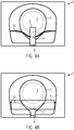
- Figur 4A und 4B
- eine Draufsicht auf weitere beispielhafte Halteplatten; und
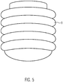
Figur 5- eine perspektivische Ansicht eines beispielhaften Abdeckelements.
- FIG. 1
- schematically the structure of an exemplary vacuum cleaner filter bag;
- FIG. 2
- the schematic structure of an exemplary holding plate in a plan view;
- FIG. 3
- a cross-section through an exemplary holding plate;
- FIGS. 4A and 4B
- a plan view of further exemplary holding plates; and
- FIG. 5
- a perspective view of an exemplary cover member.
Die Beutelwand 1 umfasst wenigstens eine Vliesstofflage, beispielsweise aus einem schmelzgesponnenen Feinfaserspinnvliesstoff (Meltblownvliesstoff) oder einem Filamentspinnvliesstoff (Spunbond).The bag wall 1 comprises at least one nonwoven fabric layer, for example of a melt-spun fine fiber spunbonded nonwoven fabric (meltblown nonwoven fabric) or a spunbonded nonwoven spunbonded nonwoven fabric.
Die Halteplatte 2 umfasst eine Grundplatte aus einem Kunststoffmaterial, beispielsweise Polypropylen.The holding
Eine Draufsicht auf eine beispielhafte Halteplatte, die in Verbindung mit einem Filterbeutel wie in
In
Die Verschlussklappe 5 wird durch ein elastisches Element 7 in Verschlussstellung vorgespannt. Das elastische Element 7 ist im Bereich einer Lagerung 8 mit der Grundplatte der Halteplatte 2 verbunden. In diesem Beispiel ist das elastische Element 7 in Schließrichtung gesehen vor der Verschlussklappe 5 angeordnet. Die Draufsicht der
Bei dem elastischen Element 7 kann es sich beispielsweise um eine Blattfeder, insbesondere eine bombierte Blattfeder, eine Schraubenfeder oder um ein Elastomerelement handeln. Wenn die Verschlussklappe 5 um das Gelenk 6 in eine geöffnete Position verschwenkt wird, wird das elastische Element 7 derart gestaucht und/oder ausgelenkt, dass eine rückstellende Federkraft hervorgerufen wird, mit der die Verschlussklappe 5 beaufschlagt wird. Wenn der Staubsaugerfilterbeutel beispielsweise aus dem Staubsaugergehäuse entfernt wird, entfällt die die Verschlussklappe 5 öffnende Kraft und die Verschlussklappe 5 wird über das elastische Element 7 wieder in die Verschlussstellung gebracht.The elastic element 7 may be, for example, a leaf spring, in particular a cambered leaf spring, a helical spring or an elastomeric element. When the
Es hat sich jedoch herausgestellt, dass bei bekannten Halteplatten die Verschlussfunktion nicht immer sichergestellt ist, da sich Fremdkörper, insbesondere Sauggut im Bereich des elastischen Elements 7 anordnet und dessen Funktion behindert.However, it has been found that in known holding plates, the closure function is not always ensured, since foreign body, in particular suction material in the region of the elastic element 7 arranges and hinders its function.
Die Halteplatte der
Es wäre auch denkbar, dass das Abdeckelement 9 nur mit der Grundplatte verbunden ist, und auf der Verschlussklappe 5 lose aufliegt. Auch eine Verbindung mit dem elastischen Element 7 ist alternativ oder zusätzlich möglich.It would also be conceivable that the
Das Abdeckelement kann eine Folie, insbesondere eine elastische Folie umfassen, beispielsweise aus einem thermoplastischen Elastomer. Die Folie kann eine Dicke von weniger als 1 mm aufweisen, insbesondere weniger als 0,5 mm, insbesondere weniger als 0,1 mm aufweisen. Es ist auch möglich, dass das Abdeckelement 9 einen Vliesstoff, ein Papier, oder ein Gewebeband umfasst oder aus solchem besteht. Auch ein Laminat unterschiedlicher Materialien, beispielsweise Vliesstoff und Folie oder Papier und Folie ist denkbar.The cover element may comprise a film, in particular an elastic film, for example of a thermoplastic elastomer. The film may have a thickness of less than 1 mm, in particular less than 0.5 mm, in particular less than 0.1 mm. It is also possible that the
Das Abdeckelement 9 kann lösbar oder nicht zerstörungsfrei lösbar mit der Grundplatte und/oder der Verschlussklappe verbunden sein. Beispielsweise kann das Abdeckelement 9 auf den gewünschten Bereich der Grundplatte und/oder der Verschlussklappe geklebt oder geschweißt sein. Für die Verbindung kann das Abdeckelement 9 auch einen selbstklebenden Bereich aufweisen. Auch eine kraftschlüssige oder formschlüssige Verbindung ist möglich, beispielsweise eine "Snap-Fit" Verbindung (Klick-Verbindung).The
Schließlich kann das Abdeckelement 9 auch über einen Spritzgussprozess mit der Grundplatte und/oder der Verschlussklappe 5 verbunden sein. In diesem Fall kann das Abdeckelement 9 gleichzeitig mit einer gegebenenfalls vorhandenen Dichtlippe 4 an die Halteplatte 2 angespritzt werden. In diesem Fall kann das Abdeckelement 9 insbesondere aus demselben Material bestehen, wie die Dichtlippe 4, insbesondere aus einem thermoplastischen Elastomer. Durch einen solchen Zweikomponentenspritzgussprozess entfällt der zusätzliche Arbeitsaufwand des Anklebens oder Anschweißens des Abdeckelements 9.Finally, the
Insbesondere wenn das Abdeckelement 9 eine Folie oder einen Vliesstoff umfasst, kann die Folie oder der Vliesstoff geprägt sein. Dadurch kann das Abdeckelement 9 eine Form erhalten, die an die Form des elastischen Elementes 7 angepasst ist, so dass das elastische Element 7 während des Öffnens der Verschlussklappe 5 nicht oder in geringerem Ausmaß in seiner Bewegung eingeschränkt wird. Alternativ oder zusätzlich kann das Abdeckelement 9 auch plissiert oder gekreppt sein. Beispielsweise kann das Abdeckelement 9 in Form eines Faltenbalgs ausgebildet sein. Dabei können die Falten des plissierten oder gekreppten Abdeckelements 9 insbesondere senkrecht zur Bewegungsrichtung der Verschlussklappe und/oder des elastischen Elements verlaufen.In particular, when the
Die Prägung des Abdeckelements 9 kann durch Heiß- oder Kaltprägung oder durch Tiefziehen bzw. Vakuumtiefziehen erfolgen.The embossing of the
Das Abdeckelement 9 kann alternativ auch aus einem Spritzgussteil oder einem Tiefziehteil bestehen, welches stoffschlüssig, formschlüssig oder kraftschlüssig mit der Grundplatte, der Verschlussklappe und/oder dem elastischen Element 7 verbunden ist, insbesondere durch Kleben oder Schweißen.The
Wenn das Abdeckelement 9 eine Steifigkeit aufweist, welche der Beweglichkeit des elastischen Elements 7 entgegenstünde, kann das Abdeckelement 9 auch ein Filmscharnier aufweisen, um welches ein Teil des Abdeckelements 9 verschwenkt werden kann. Alternativ oder zusätzlich kann das Abdeckelement 9 zwei- oder mehrstückig ausgeführt werden, wobei die Teile des mehrstückigen Abdeckelements formschlüssig oder stoffschlüssig miteinander verbunden sind, insbesondere über Schweißen, Kleben oder Klicken (Snap-Fit).If the
Das elastische Element 7 kann eine Schraubenfeder sein. In diesem Fall kann alternativ oder zusätzlich zum Abdeckelement 9 der
Durch diese Kunststoffummantelung ist es möglich, zu verhindern, dass Staub zwischen die Windungen der Schraubenfeder gelangt, was eine Verminderung der Funktion der Schraubenfeder mit sich bringen könnte.By this plastic coating, it is possible to prevent dust from getting between the turns of the coil spring, which could bring a reduction in the function of the coil spring with it.
Alternativ zur Schraubenfeder kann das elastische Element 7 auch durch eine Elastomerschnur oder ein Elastomerband gebildet werden. Für das elastische Element kann insbesondere ein vulkanisiertes Silicon-Elastomer Anwendung finden. Dieses hat den Vorteil, dass es an die Halteplatte angespritzt werden kann. Insbesondere kommt vernetztes Flüssigsilicon (Liquid Silicone Rubber, LSR) oder vernetztes Festsilicon (High-Consistency Rubber, HCR) in Frage. Das elastische Element aus einem Elastomer besitzt eine Eigenelastizität. Zusätzlich kann das elastische Element auch noch eine Form aufweisen, welche durch ihre Struktur eine weitere Elastizität verleiht.As an alternative to the helical spring, the elastic element 7 can also be formed by an elastomeric cord or an elastomeric band. In particular, a vulcanized silicone elastomer can be used for the elastic element. This has the advantage that it can be molded onto the retaining plate. In particular, crosslinked liquid silicone (liquid silicone rubber, LSR) or crosslinked solid silicone (high-consistency rubber, HCR) come into question. The elastic member made of an elastomer has inherent elasticity. In addition, the elastic element may also have a shape which imparts a further elasticity through its structure.
Es versteht sich, dass in den zuvor beschriebenen Ausführungsbeispielen genannte Merkmale nicht auf diese speziellen Kombinationen beschränkt und auch in beliebigen anderen Kombinationen möglich sind. Weiterhin versteht es sich, dass in den Figuren weder der gezeigte Staubsaugerfilterbeutel noch die Elemente der Halteplatte in einer realistischen Dimensionierung wiedergegeben sind. Außerdem sind auch die Geometrien beziehungsweise der gezeigten Elemente nicht auf die gezeigten Beispiele beschränkt.It is understood that in the embodiments described above mentioned features are not limited to these specific combinations and also possible in any other combinations. Furthermore, it is understood that in the figures, neither the vacuum cleaner filter bag shown nor the elements of the holding plate are reproduced in a realistic dimensioning. In addition, the geometries or the elements shown are not limited to the examples shown.
Claims (15)
- Holding plate (2) for a vacuum cleaner filter bag, comprising a base plate in which a passage opening (3) is formed, and a closure flap (5) for closing the passage opening (3),
wherein the closure flap (5) is biased via an elastic element (7; 10) in closed position,
characterized in that
a cover element (9) which is connected to the base plate, the closure flap (5) and/or the elastic element (7) is provided, which covers the elastic element (7) partially or completely, wherein the cover element (9) abuts in a surface portion of the closure flap (5) on the closure flap (5), said surface portion surrounding the elastic element (7; 10) at least on two sides. - Holding plate (2) according to claim 1, wherein the elastic element (7; 10) is arranged, viewed in the closing direction, in front of the closure flap (5).
- Holding plate (2) according to claim 1 or 2, wherein the cover element (9) comprises a film, a nonwoven fabric and/or a paper.
- Holding plate (2) according to one of the preceding claims, wherein the cover element (9) is glued or welded with a part of the holding plate (2), in particular the base plate, or injection-molded onto a part of the holding plate (2), in particular the base plate.
- Holding plate (2) according to one of the preceding claims, wherein the cover element (9) has an embossment which is adapted in particular to the shape of the elastic element (7).
- Holding plate (2) according to one of the preceding claims, wherein the cover element (9) is pleated or creped.
- Holding plate (2) according to one of the preceding claims, wherein the cover element is formed in several pieces.
- Holding plate (2) according to claim 7, wherein the parts of the multi-piece cover element are positively or materially connected to each other.
- Holding plate (2) according to one of the preceding claims, wherein the cover element comprises a pivot axis about which a part of the cover is pivotable, in particular wherein the pivot axis is formed by a film hinge.
- Holding plate (2) according to one of the preceding claims, wherein the elastic element (7; 10) comprises an elastomer or consists of an elastomer.
- Holding plate (2) according to claim 10, wherein the elastic element (7; 10) is injection-molded onto a part of the holding plate (2), in particular the base plate.
- Holding plate (2) according to one of claims 1-9, wherein the elastic element (7; 10) is a helical spring, and wherein the helical spring is at least partially surrounded by a sheath.
- Holding plate (2) according to one of the preceding claims, wherein the elastic element (7; 10) rests loosely on the base plate and is limited by the cover element (9) in its position to a predetermined range.
- Vacuum cleaner filter bag comprising a bag wall (1) and a holding plate (2) connected thereto according to one of the preceding claims.
- Method for producing a holding plate (2) for a vacuum cleaner filter bag, comprising the steps of:providing a base plate with a passage opening (3) and providing a closure flap (5) for closing the passage opening (3);arranging an elastic element (7; 10) on the base plate and/or the closure flap (5); andconnecting a cover element (9) to the base plate, the closure flap and/or the elastic element (7; 10) so that the elastic element (7; 10) is partially or completely covered by the cover element (9), wherein the cover element (9) is arranged such that it abuts in a surface portion of the closure flap (5) on the closure flap (5), said surface portion surrounding the elastic element (7; 10) at least on two sides.
Priority Applications (9)
| Application Number | Priority Date | Filing Date | Title |
|---|---|---|---|
| ES16160969.8T ES2673309T3 (en) | 2016-03-17 | 2016-03-17 | Support plate with improved closure element |
| DK16160969.8T DK3219237T3 (en) | 2016-03-17 | 2016-03-17 | Holding plate with improved closure element |
| PL16160969T PL3219237T3 (en) | 2016-03-17 | 2016-03-17 | Holding plate with improved closure element |
| EP16160969.8A EP3219237B1 (en) | 2016-03-17 | 2016-03-17 | Holding plate with improved closure element |
| PCT/EP2017/056228 WO2017158085A1 (en) | 2016-03-17 | 2017-03-16 | Holding board with an improved closure element |
| RU2018131846A RU2701569C1 (en) | 2016-03-17 | 2017-03-16 | Retaining plate with improved closing element |
| US16/085,409 US10939788B2 (en) | 2016-03-17 | 2017-03-16 | Retaining plate with improved sealing |
| CN201780025468.8A CN109068917B (en) | 2016-03-17 | 2017-03-16 | Retaining plate with improved sealing |
| AU2017235055A AU2017235055A1 (en) | 2016-03-17 | 2017-03-16 | Holding board with an improved closure element |
Applications Claiming Priority (1)
| Application Number | Priority Date | Filing Date | Title |
|---|---|---|---|
| EP16160969.8A EP3219237B1 (en) | 2016-03-17 | 2016-03-17 | Holding plate with improved closure element |
Publications (2)
| Publication Number | Publication Date |
|---|---|
| EP3219237A1 EP3219237A1 (en) | 2017-09-20 |
| EP3219237B1 true EP3219237B1 (en) | 2018-05-09 |
Family
ID=55542599
Family Applications (1)
| Application Number | Title | Priority Date | Filing Date |
|---|---|---|---|
| EP16160969.8A Active EP3219237B1 (en) | 2016-03-17 | 2016-03-17 | Holding plate with improved closure element |
Country Status (9)
| Country | Link |
|---|---|
| US (1) | US10939788B2 (en) |
| EP (1) | EP3219237B1 (en) |
| CN (1) | CN109068917B (en) |
| AU (1) | AU2017235055A1 (en) |
| DK (1) | DK3219237T3 (en) |
| ES (1) | ES2673309T3 (en) |
| PL (1) | PL3219237T3 (en) |
| RU (1) | RU2701569C1 (en) |
| WO (1) | WO2017158085A1 (en) |
Family Cites Families (64)
| Publication number | Priority date | Publication date | Assignee | Title |
|---|---|---|---|---|
| US3533868A (en) | 1967-02-15 | 1970-10-13 | Cons Foods Corp | Method of manufacturing end closures for a vacuum cleaner dust bag |
| DE9016939U1 (en) | 1990-12-17 | 1991-04-04 | Wolfgang B. Schroeter Gmbh, 4973 Vlotho, De | |
| DE4415350A1 (en) | 1994-05-02 | 1995-11-16 | Vorwerk Co Interholding | Dust filter bag for a vacuum cleaner |
| FR2721188B1 (en) | 1994-06-21 | 1996-08-09 | Delphy | Device for automatically closing a vacuum cleaner dust bag with a valve. |
| DE29615163U1 (en) | 1996-08-31 | 1996-11-21 | Hafner Ingo Dipl Ing | Device for collecting dust, dirt and the like |
| CZ20004184A3 (en) | 1998-05-11 | 2001-10-17 | Airflo Europe N. V. | Vacuum cleaner bag |
| DE29924781U1 (en) | 1998-05-11 | 2005-08-11 | Airflo Europe N.V. | Vacuum cleaner bag and improved vacuum cleaner bag |
| DE19919809C2 (en) | 1999-04-30 | 2003-02-06 | Fibermark Gessner Gmbh & Co | Dust filter bag containing nanofiber fleece |
| US6372004B1 (en) | 1999-07-08 | 2002-04-16 | Airflo Europe N.V. | High efficiency depth filter and methods of forming the same |
| DE19948909A1 (en) | 1999-10-11 | 2001-04-12 | Vorwerk Co Interholding | Filter bag for a vacuum cleaner |
| DE20010049U1 (en) | 2000-06-03 | 2000-09-14 | Aichner Filter Gmbh | Dust filter bags, in particular for a vacuum cleaner |
| DE20101466U1 (en) | 2001-01-27 | 2001-04-19 | Wolf Gmbh | Filter device that can be used in a vacuum cleaner |
| DE10120223B4 (en) | 2001-04-24 | 2005-08-25 | Carl Freudenberg Kg | Multi-layer air filter and its use |
| DE10209718A1 (en) | 2002-03-06 | 2003-09-25 | Edison Fatehpour | Spring element for a flap of a filter bag |
| DE10221694B4 (en) | 2002-05-16 | 2018-07-12 | Branofilter Gmbh | Multi-layer filter construction, use of such a multi-layer filter assembly, dust filter bag, bag filter bag, pleated filter, surface exhaust filter and air filter for motor vehicles |
| EP1804635B2 (en) | 2005-11-22 | 2011-02-16 | Eurofilters Holding N.V. | Vacuum cleaner filter bag and use of said bag |
| EP1795427B2 (en) | 2005-12-12 | 2014-09-24 | Inventus Engineering GmbH | Energy absorbing element |
| DE102005059214B4 (en) | 2005-12-12 | 2007-10-25 | Eurofilters N.V. | Filter bag for a vacuum cleaner |
| US7938276B2 (en) | 2006-02-01 | 2011-05-10 | Mechanical Manufacturing Corporation | Filtration architecture for optimized performance |
| DE102006017553B3 (en) | 2006-04-13 | 2007-12-27 | Eurofilters N.V. | Filter bag for a vacuum cleaner |
| AU2007241314B2 (en) | 2006-04-25 | 2010-11-18 | Eurofilters Holding N.V. | Holding plate for a vacuum cleaner bag |
| EP1875848A3 (en) | 2006-04-25 | 2008-02-27 | Eurofilters Holding N.V | Holder plate for a vacuum cleaner filter bag |
| DE102006037456A1 (en) | 2006-08-10 | 2008-02-14 | Vorwerk & Co. Interholding Gmbh | Filter bag e.g. for vacuum cleaner, has plate and associated plate and opening provided for loading bag into vacuum cleaner |
| ES2361118T3 (en) | 2006-11-03 | 2011-06-14 | Eurofilters Holding N.V. | ANTIBACTERIAL VACUUM FILTER BAG. |
| DE102006055890A1 (en) | 2006-11-27 | 2008-05-29 | Wolf Gmbh & Co. Kg | Fastening device for vacuum cleaner's filter bag, has connection plate with hole aligned with opening of retaining plate and connection section covering opening, where connection plate is made of material other than that of retaining plate |
| DE202007018376U1 (en) | 2007-07-06 | 2008-07-03 | Eurofilters Holding N.V. | Vacuum cleaner filter bag |
| DE102008046200B4 (en) | 2007-09-28 | 2016-09-15 | Vorwerk & Co. Interholding Gmbh | Filter bag for a vacuum cleaner |
| DE202007014164U1 (en) | 2007-10-01 | 2007-12-13 | Branofilter Gmbh | Filter bag for vacuum cleaners |
| DE102007062028B4 (en) | 2007-12-21 | 2009-09-03 | Arwed Löseke Papierverarbeitung und Druckerei GmbH | Method for producing a dust filter bag and dust filter bag |
| DE202008003248U1 (en) | 2008-03-07 | 2008-05-08 | Eurofilters Holding N.V. | Vacuum cleaner filter bag |
| ES2440722T3 (en) | 2008-03-07 | 2014-01-30 | Eurofilters Holding N.V. | Vacuum cleaner filter bag |
| US7972458B2 (en) | 2008-03-10 | 2011-07-05 | Uv Corporation | Filter material and process for producing same |
| DE202008006904U1 (en) | 2008-05-21 | 2009-10-15 | Wolf Pvg Gmbh & Co. Kg | Holding plate for a vacuum cleaner bag |
| DE202008004733U1 (en) | 2008-07-13 | 2008-10-02 | Wulbrandt, Herbert | Holding plate for vacuum cleaner bags with automatic closure |
| DE102008041227A1 (en) | 2008-08-13 | 2010-02-18 | BSH Bosch und Siemens Hausgeräte GmbH | Dust bags |
| DE202008018054U1 (en) * | 2008-08-29 | 2011-04-28 | Vorwerk & Co. Interholding Gmbh | Filter bag for a vacuum cleaner |
| CN101747596A (en) | 2008-12-11 | 2010-06-23 | 王世和 | Preparation method of recycled polyester chip microfilaments and usage thereof |
| EP2263508B1 (en) | 2009-06-19 | 2015-08-05 | Eurofilters N.V. | Flat bag for a vacuum cleaner with at least two diffusers |
| DE102009035717A1 (en) | 2009-07-31 | 2011-02-10 | Miele & Cie. Kg | Method for indicating a degree of filling of a dust bag and control device for carrying out the method |
| WO2011017457A2 (en) | 2009-08-04 | 2011-02-10 | The Xextex Corporation | High efficiency low pressure drop synthetic fiber based air filter made completely from post consumer waste materials |
| DK2301402T3 (en) * | 2009-09-25 | 2014-03-10 | Eurofilters Holding Nv | A holder plate for a vacuum cleaner filter bag |
| EP2311359B1 (en) | 2009-10-19 | 2016-04-27 | Eurofilters Holding N.V. | Vacuum cleaner filter bag |
| US20130005209A1 (en) | 2009-11-13 | 2013-01-03 | Carsten Andersen | Non-woven fibre product comprising fibres of recycled material |
| PL2366319T3 (en) * | 2010-03-19 | 2015-07-31 | Eurofilters Holding Nv | Vacuum cleaner filter bag |
| DE102010060175A1 (en) * | 2010-09-06 | 2012-03-08 | Vorwerk & Co. Interholding Gmbh | Dust bag filter for vacuum cleaner, particularly electric vacuum cleaner, has entry opening formed in holding plate, where closure flap is associated with entry opening |
| DE102010046567A1 (en) | 2010-09-27 | 2012-03-29 | Sandler Ag | Multi-layer filter construction |
| DE102011008117A1 (en) | 2010-10-05 | 2012-04-05 | Herbert Wulbrandt | Retaining plate for vacuum cleaner bags, is provided with sealing flap and elastic element, which is formed cord-shaped and exert on sealing flap |
| DE102010060353A1 (en) | 2010-11-04 | 2012-05-10 | Papierverarbeitung Görlitz GmbH | Dust filter bag for vacuum cleaner, has receiving opening formed in bag wall toward air inlet opening, and sealing element made of flexible material, where diameter of receiving opening is smaller than or same as diameter of inlet opening |
| DE102011105384A1 (en) | 2011-06-20 | 2012-12-20 | Alexander Patzig | Retaining plate for vacuum cleaner bag, has closure comprising a retaining element that is fitted with sealing element such that closure is completely rested on plate main structure |
| DE202011052208U1 (en) * | 2011-12-06 | 2013-03-08 | Wolf Pvg Gmbh & Co. Kg | Holding device for a vacuum cleaner bag |
| EP2606799B1 (en) * | 2011-12-22 | 2015-02-25 | Eurofilters N.V. | Holding plate |
| US20130177264A1 (en) | 2012-01-10 | 2013-07-11 | Fka Distributing Co., Llc | Fabric And Method of Producing Same |
| DE102012012999B4 (en) | 2012-01-24 | 2017-06-14 | Elku Bauteile GmbH | Holding plate for vacuum cleaner bags with automatic closure with an elastic element |
| US9211491B2 (en) | 2012-11-06 | 2015-12-15 | Lydall, Inc. | Air filtration media and processes for manufacturing the same |
| DE102013012083A1 (en) * | 2012-11-19 | 2014-05-22 | Vorwerk & Co. Interholding Gmbh | Filter bag for a vacuum cleaner |
| DE202013001096U1 (en) | 2013-02-05 | 2013-03-05 | Branofilter Gmbh | Dust filter bag for vacuum cleaners |
| DE202013100862U1 (en) | 2013-02-28 | 2013-03-13 | Wolf Pvg Gmbh & Co. Kg | Holding plate for a vacuum cleaner bag |
| DE202013103508U1 (en) | 2013-08-05 | 2013-08-22 | Wolf Pvg Gmbh & Co. Kg | Dust bags |
| DE202014100563U1 (en) | 2014-02-10 | 2015-05-15 | Wolf Pvg Gmbh & Co. Kg | Dust bags |
| CN104224049B (en) * | 2014-09-19 | 2017-07-04 | 上海曾曦净化科技有限公司 | A kind of hardened structure of bayonet socket for vacuum cleaner filter bag |
| DE202015101218U1 (en) | 2015-03-10 | 2015-04-01 | Branofilter Gmbh | Dust filter bag for use in a vacuum cleaner |
| EP3219375B1 (en) | 2016-03-17 | 2018-09-26 | Eurofilters N.V. | Vacuum cleaner filter bag containing dust and/or fibrous recycled material |
| EP3219374B1 (en) | 2016-03-17 | 2019-05-08 | Eurofilters N.V. | Vacuum cleaner filter bag made from recycled plastics |
| EP3219373B1 (en) | 2016-03-17 | 2018-03-07 | Eurofilters N.V. | Vacuum cleaner filter bag containing recycled textile materials and/or cotton linters |
-
2016
- 2016-03-17 EP EP16160969.8A patent/EP3219237B1/en active Active
- 2016-03-17 DK DK16160969.8T patent/DK3219237T3/en active
- 2016-03-17 PL PL16160969T patent/PL3219237T3/en unknown
- 2016-03-17 ES ES16160969.8T patent/ES2673309T3/en active Active
-
2017
- 2017-03-16 CN CN201780025468.8A patent/CN109068917B/en active Active
- 2017-03-16 RU RU2018131846A patent/RU2701569C1/en active
- 2017-03-16 WO PCT/EP2017/056228 patent/WO2017158085A1/en active Application Filing
- 2017-03-16 AU AU2017235055A patent/AU2017235055A1/en not_active Abandoned
- 2017-03-16 US US16/085,409 patent/US10939788B2/en active Active
Non-Patent Citations (1)
| Title |
|---|
| None * |
Also Published As
| Publication number | Publication date |
|---|---|
| CN109068917A (en) | 2018-12-21 |
| EP3219237A1 (en) | 2017-09-20 |
| ES2673309T3 (en) | 2018-06-21 |
| WO2017158085A1 (en) | 2017-09-21 |
| CN109068917B (en) | 2022-10-04 |
| RU2701569C1 (en) | 2019-09-30 |
| PL3219237T3 (en) | 2018-10-31 |
| US20190045990A1 (en) | 2019-02-14 |
| DK3219237T3 (en) | 2018-07-30 |
| AU2017235055A1 (en) | 2018-09-27 |
| US10939788B2 (en) | 2021-03-09 |
Similar Documents
| Publication | Publication Date | Title |
|---|---|---|
| EP2301402B1 (en) | Holding plate for a vacuum cleaner filter bag | |
| EP2772173B1 (en) | Filter bag for a vacuum cleaner and method for producing a holding plate for a filter bag | |
| EP0912225B1 (en) | Disk, in particular the front disk of a filter element | |
| EP2025278B1 (en) | Vacuum cleaner filter bag | |
| EP2044874B1 (en) | Filter bag for a vacuum cleaner | |
| WO2007121979A1 (en) | Holding plate for a vacuum cleaner bag | |
| EP3386363B1 (en) | Method for forming a strong connection between a holding plate and the wall of a vacuum cleaner filter bag and vacuum cleaner filter bag | |
| EP2311358A1 (en) | Holding plate for a vacuum cleaner filter bag | |
| DE102007062028A1 (en) | Dust filter bag manufacturing method for vacuum cleaner, involves forming rubber-like elastic layer on clearance hole in bag wall, and forming sealing by boundary area of clearance hole | |
| DE202005021619U1 (en) | filter bag | |
| EP1787561A1 (en) | Vacuum cleaner dust bag with closure means | |
| EP2067427B1 (en) | Dust filter bag for a vacuum cleaner | |
| EP2772172A2 (en) | Holding plate and method for producing a holding plate | |
| DE202009004433U1 (en) | Block bottom bag with additional weld and Sollfaltlinien | |
| EP3219237B1 (en) | Holding plate with improved closure element | |
| EP3530170B1 (en) | Supporting plate with centring device | |
| EP3219236B1 (en) | Holding plate with improved closure | |
| DE102012010079A1 (en) | Coupling device for coupling a dust filter bag with an inlet device of a vacuum cleaner | |
| EP3530171B1 (en) | Holding plate with sealing element | |
| WO2018115269A1 (en) | Retainer panel for a vacuum cleaner bag, with seal | |
| EP0787460B1 (en) | Connection piece for a vacuum cleaner dustbag | |
| WO2007059938A1 (en) | Vacuum cleaner filter bag comprising a sealing device | |
| EP4031460A1 (en) | Valve for a packaging container | |
| DE202004008971U1 (en) | Vacuum cleaner filter bag has plastics connecting plate for connection to machine having flexible sealing aperture with smaller diameter than opening in plate | |
| EP1787564B1 (en) | Holding plate with a deflection device for a vacuum cleaner dust bag |
Legal Events
| Date | Code | Title | Description |
|---|---|---|---|
| PUAI | Public reference made under article 153(3) epc to a published international application that has entered the european phase |
Free format text: ORIGINAL CODE: 0009012 |
|
| STAA | Information on the status of an ep patent application or granted ep patent |
Free format text: STATUS: REQUEST FOR EXAMINATION WAS MADE |
|
| 17P | Request for examination filed |
Effective date: 20170201 |
|
| AK | Designated contracting states |
Kind code of ref document: A1 Designated state(s): AL AT BE BG CH CY CZ DE DK EE ES FI FR GB GR HR HU IE IS IT LI LT LU LV MC MK MT NL NO PL PT RO RS SE SI SK SM TR |
|
| AX | Request for extension of the european patent |
Extension state: BA ME |
|
| GRAP | Despatch of communication of intention to grant a patent |
Free format text: ORIGINAL CODE: EPIDOSNIGR1 |
|
| STAA | Information on the status of an ep patent application or granted ep patent |
Free format text: STATUS: GRANT OF PATENT IS INTENDED |
|
| INTG | Intention to grant announced |
Effective date: 20171130 |
|
| GRAS | Grant fee paid |
Free format text: ORIGINAL CODE: EPIDOSNIGR3 |
|
| GRAA | (expected) grant |
Free format text: ORIGINAL CODE: 0009210 |
|
| STAA | Information on the status of an ep patent application or granted ep patent |
Free format text: STATUS: THE PATENT HAS BEEN GRANTED |
|
| AK | Designated contracting states |
Kind code of ref document: B1 Designated state(s): AL AT BE BG CH CY CZ DE DK EE ES FI FR GB GR HR HU IE IS IT LI LT LU LV MC MK MT NL NO PL PT RO RS SE SI SK SM TR |
|
| REG | Reference to a national code |
Ref country code: GB Ref legal event code: FG4D Free format text: NOT ENGLISH |
|
| REG | Reference to a national code |
Ref country code: CH Ref legal event code: EP Ref country code: AT Ref legal event code: REF Ref document number: 996749 Country of ref document: AT Kind code of ref document: T Effective date: 20180515 |
|
| REG | Reference to a national code |
Ref country code: IE Ref legal event code: FG4D Free format text: LANGUAGE OF EP DOCUMENT: GERMAN |
|
| REG | Reference to a national code |
Ref country code: DE Ref legal event code: R096 Ref document number: 502016001005 Country of ref document: DE |
|
| REG | Reference to a national code |
Ref country code: ES Ref legal event code: FG2A Ref document number: 2673309 Country of ref document: ES Kind code of ref document: T3 Effective date: 20180621 |
|
| REG | Reference to a national code |
Ref country code: SE Ref legal event code: TRGR |
|
| REG | Reference to a national code |
Ref country code: DK Ref legal event code: T3 Effective date: 20180719 |
|
| REG | Reference to a national code |
Ref country code: NL Ref legal event code: FP |
|
| REG | Reference to a national code |
Ref country code: LT Ref legal event code: MG4D |
|
| PG25 | Lapsed in a contracting state [announced via postgrant information from national office to epo] |
Ref country code: BG Free format text: LAPSE BECAUSE OF FAILURE TO SUBMIT A TRANSLATION OF THE DESCRIPTION OR TO PAY THE FEE WITHIN THE PRESCRIBED TIME-LIMIT Effective date: 20180809 Ref country code: NO Free format text: LAPSE BECAUSE OF FAILURE TO SUBMIT A TRANSLATION OF THE DESCRIPTION OR TO PAY THE FEE WITHIN THE PRESCRIBED TIME-LIMIT Effective date: 20180809 Ref country code: LT Free format text: LAPSE BECAUSE OF FAILURE TO SUBMIT A TRANSLATION OF THE DESCRIPTION OR TO PAY THE FEE WITHIN THE PRESCRIBED TIME-LIMIT Effective date: 20180509 Ref country code: FI Free format text: LAPSE BECAUSE OF FAILURE TO SUBMIT A TRANSLATION OF THE DESCRIPTION OR TO PAY THE FEE WITHIN THE PRESCRIBED TIME-LIMIT Effective date: 20180509 |
|
| PG25 | Lapsed in a contracting state [announced via postgrant information from national office to epo] |
Ref country code: HR Free format text: LAPSE BECAUSE OF FAILURE TO SUBMIT A TRANSLATION OF THE DESCRIPTION OR TO PAY THE FEE WITHIN THE PRESCRIBED TIME-LIMIT Effective date: 20180509 Ref country code: LV Free format text: LAPSE BECAUSE OF FAILURE TO SUBMIT A TRANSLATION OF THE DESCRIPTION OR TO PAY THE FEE WITHIN THE PRESCRIBED TIME-LIMIT Effective date: 20180509 Ref country code: GR Free format text: LAPSE BECAUSE OF FAILURE TO SUBMIT A TRANSLATION OF THE DESCRIPTION OR TO PAY THE FEE WITHIN THE PRESCRIBED TIME-LIMIT Effective date: 20180810 Ref country code: RS Free format text: LAPSE BECAUSE OF FAILURE TO SUBMIT A TRANSLATION OF THE DESCRIPTION OR TO PAY THE FEE WITHIN THE PRESCRIBED TIME-LIMIT Effective date: 20180509 |
|
| PG25 | Lapsed in a contracting state [announced via postgrant information from national office to epo] |
Ref country code: EE Free format text: LAPSE BECAUSE OF FAILURE TO SUBMIT A TRANSLATION OF THE DESCRIPTION OR TO PAY THE FEE WITHIN THE PRESCRIBED TIME-LIMIT Effective date: 20180509 Ref country code: SK Free format text: LAPSE BECAUSE OF FAILURE TO SUBMIT A TRANSLATION OF THE DESCRIPTION OR TO PAY THE FEE WITHIN THE PRESCRIBED TIME-LIMIT Effective date: 20180509 Ref country code: RO Free format text: LAPSE BECAUSE OF FAILURE TO SUBMIT A TRANSLATION OF THE DESCRIPTION OR TO PAY THE FEE WITHIN THE PRESCRIBED TIME-LIMIT Effective date: 20180509 Ref country code: CZ Free format text: LAPSE BECAUSE OF FAILURE TO SUBMIT A TRANSLATION OF THE DESCRIPTION OR TO PAY THE FEE WITHIN THE PRESCRIBED TIME-LIMIT Effective date: 20180509 |
|
| REG | Reference to a national code |
Ref country code: DE Ref legal event code: R097 Ref document number: 502016001005 Country of ref document: DE |
|
| PG25 | Lapsed in a contracting state [announced via postgrant information from national office to epo] |
Ref country code: SM Free format text: LAPSE BECAUSE OF FAILURE TO SUBMIT A TRANSLATION OF THE DESCRIPTION OR TO PAY THE FEE WITHIN THE PRESCRIBED TIME-LIMIT Effective date: 20180509 |
|
| PLBE | No opposition filed within time limit |
Free format text: ORIGINAL CODE: 0009261 |
|
| STAA | Information on the status of an ep patent application or granted ep patent |
Free format text: STATUS: NO OPPOSITION FILED WITHIN TIME LIMIT |
|
| 26N | No opposition filed |
Effective date: 20190212 |
|
| PG25 | Lapsed in a contracting state [announced via postgrant information from national office to epo] |
Ref country code: MC Free format text: LAPSE BECAUSE OF FAILURE TO SUBMIT A TRANSLATION OF THE DESCRIPTION OR TO PAY THE FEE WITHIN THE PRESCRIBED TIME-LIMIT Effective date: 20180509 |
|
| REG | Reference to a national code |
Ref country code: CH Ref legal event code: PL |
|
| PG25 | Lapsed in a contracting state [announced via postgrant information from national office to epo] |
Ref country code: LU Free format text: LAPSE BECAUSE OF NON-PAYMENT OF DUE FEES Effective date: 20190317 Ref country code: AL Free format text: LAPSE BECAUSE OF FAILURE TO SUBMIT A TRANSLATION OF THE DESCRIPTION OR TO PAY THE FEE WITHIN THE PRESCRIBED TIME-LIMIT Effective date: 20180509 |
|
| PG25 | Lapsed in a contracting state [announced via postgrant information from national office to epo] |
Ref country code: CH Free format text: LAPSE BECAUSE OF NON-PAYMENT OF DUE FEES Effective date: 20190331 Ref country code: LI Free format text: LAPSE BECAUSE OF NON-PAYMENT OF DUE FEES Effective date: 20190331 Ref country code: IE Free format text: LAPSE BECAUSE OF NON-PAYMENT OF DUE FEES Effective date: 20190317 |
|
| PG25 | Lapsed in a contracting state [announced via postgrant information from national office to epo] |
Ref country code: TR Free format text: LAPSE BECAUSE OF FAILURE TO SUBMIT A TRANSLATION OF THE DESCRIPTION OR TO PAY THE FEE WITHIN THE PRESCRIBED TIME-LIMIT Effective date: 20180509 |
|
| PG25 | Lapsed in a contracting state [announced via postgrant information from national office to epo] |
Ref country code: MT Free format text: LAPSE BECAUSE OF FAILURE TO SUBMIT A TRANSLATION OF THE DESCRIPTION OR TO PAY THE FEE WITHIN THE PRESCRIBED TIME-LIMIT Effective date: 20180509 Ref country code: PT Free format text: LAPSE BECAUSE OF FAILURE TO SUBMIT A TRANSLATION OF THE DESCRIPTION OR TO PAY THE FEE WITHIN THE PRESCRIBED TIME-LIMIT Effective date: 20180910 |
|
| PG25 | Lapsed in a contracting state [announced via postgrant information from national office to epo] |
Ref country code: CY Free format text: LAPSE BECAUSE OF FAILURE TO SUBMIT A TRANSLATION OF THE DESCRIPTION OR TO PAY THE FEE WITHIN THE PRESCRIBED TIME-LIMIT Effective date: 20180509 |
|
| PG25 | Lapsed in a contracting state [announced via postgrant information from national office to epo] |
Ref country code: IS Free format text: LAPSE BECAUSE OF FAILURE TO SUBMIT A TRANSLATION OF THE DESCRIPTION OR TO PAY THE FEE WITHIN THE PRESCRIBED TIME-LIMIT Effective date: 20180909 |
|
| PG25 | Lapsed in a contracting state [announced via postgrant information from national office to epo] |
Ref country code: HU Free format text: LAPSE BECAUSE OF FAILURE TO SUBMIT A TRANSLATION OF THE DESCRIPTION OR TO PAY THE FEE WITHIN THE PRESCRIBED TIME-LIMIT; INVALID AB INITIO Effective date: 20160317 |
|
| PG25 | Lapsed in a contracting state [announced via postgrant information from national office to epo] |
Ref country code: SI Free format text: LAPSE BECAUSE OF FAILURE TO SUBMIT A TRANSLATION OF THE DESCRIPTION OR TO PAY THE FEE WITHIN THE PRESCRIBED TIME-LIMIT Effective date: 20180509 |
|
| REG | Reference to a national code |
Ref country code: AT Ref legal event code: MM01 Ref document number: 996749 Country of ref document: AT Kind code of ref document: T Effective date: 20210317 |
|
| PG25 | Lapsed in a contracting state [announced via postgrant information from national office to epo] |
Ref country code: MK Free format text: LAPSE BECAUSE OF FAILURE TO SUBMIT A TRANSLATION OF THE DESCRIPTION OR TO PAY THE FEE WITHIN THE PRESCRIBED TIME-LIMIT Effective date: 20180509 |
|
| PG25 | Lapsed in a contracting state [announced via postgrant information from national office to epo] |
Ref country code: AT Free format text: LAPSE BECAUSE OF NON-PAYMENT OF DUE FEES Effective date: 20210317 |
|
| PGFP | Annual fee paid to national office [announced via postgrant information from national office to epo] |
Ref country code: FR Payment date: 20230322 Year of fee payment: 8 Ref country code: DK Payment date: 20230321 Year of fee payment: 8 |
|
| PGFP | Annual fee paid to national office [announced via postgrant information from national office to epo] |
Ref country code: SE Payment date: 20230322 Year of fee payment: 8 Ref country code: PL Payment date: 20230313 Year of fee payment: 8 Ref country code: GB Payment date: 20230322 Year of fee payment: 8 Ref country code: DE Payment date: 20230323 Year of fee payment: 8 Ref country code: BE Payment date: 20230322 Year of fee payment: 8 |
|
| PGFP | Annual fee paid to national office [announced via postgrant information from national office to epo] |
Ref country code: NL Payment date: 20230325 Year of fee payment: 8 |
|
| PGFP | Annual fee paid to national office [announced via postgrant information from national office to epo] |
Ref country code: IT Payment date: 20230331 Year of fee payment: 8 Ref country code: ES Payment date: 20230403 Year of fee payment: 8 |
|
| PGFP | Annual fee paid to national office [announced via postgrant information from national office to epo] |
Ref country code: NL Payment date: 20240320 Year of fee payment: 9 |