EP1787564B1 - Holding plate with a deflection device for a vacuum cleaner dust bag - Google Patents
Holding plate with a deflection device for a vacuum cleaner dust bag Download PDFInfo
- Publication number
- EP1787564B1 EP1787564B1 EP06006750.1A EP06006750A EP1787564B1 EP 1787564 B1 EP1787564 B1 EP 1787564B1 EP 06006750 A EP06006750 A EP 06006750A EP 1787564 B1 EP1787564 B1 EP 1787564B1
- Authority
- EP
- European Patent Office
- Prior art keywords
- holding plate
- deflection device
- vacuum cleaner
- plate according
- passage opening
- Prior art date
- Legal status (The legal status is an assumption and is not a legal conclusion. Google has not performed a legal analysis and makes no representation as to the accuracy of the status listed.)
- Active
Links
- 239000000428 dust Substances 0.000 title description 4
- 238000007789 sealing Methods 0.000 claims description 19
- 239000000463 material Substances 0.000 claims description 13
- 239000004033 plastic Substances 0.000 claims description 8
- 239000006260 foam Substances 0.000 claims description 5
- 229920001971 elastomer Polymers 0.000 claims description 4
- 239000000806 elastomer Substances 0.000 claims description 2
- 239000000123 paper Substances 0.000 claims description 2
- 239000002245 particle Substances 0.000 description 7
- 238000011161 development Methods 0.000 description 5
- 230000018109 developmental process Effects 0.000 description 5
- 239000012065 filter cake Substances 0.000 description 5
- 238000004519 manufacturing process Methods 0.000 description 4
- 238000010276 construction Methods 0.000 description 3
- 238000009826 distribution Methods 0.000 description 3
- 238000005452 bending Methods 0.000 description 2
- 230000002349 favourable effect Effects 0.000 description 2
- 230000005294 ferromagnetic effect Effects 0.000 description 2
- 238000001914 filtration Methods 0.000 description 2
- 239000004743 Polypropylene Substances 0.000 description 1
- 238000004026 adhesive bonding Methods 0.000 description 1
- 230000009286 beneficial effect Effects 0.000 description 1
- 230000003111 delayed effect Effects 0.000 description 1
- 239000011888 foil Substances 0.000 description 1
- 238000002347 injection Methods 0.000 description 1
- 239000007924 injection Substances 0.000 description 1
- 238000001746 injection moulding Methods 0.000 description 1
- 238000000465 moulding Methods 0.000 description 1
- 239000004745 nonwoven fabric Substances 0.000 description 1
- -1 polypropylene Polymers 0.000 description 1
- 229920001155 polypropylene Polymers 0.000 description 1
- 239000011148 porous material Substances 0.000 description 1
- 239000003566 sealing material Substances 0.000 description 1
- 239000007787 solid Substances 0.000 description 1
- 238000003860 storage Methods 0.000 description 1
- 229920002725 thermoplastic elastomer Polymers 0.000 description 1
- 238000009827 uniform distribution Methods 0.000 description 1
- 238000003466 welding Methods 0.000 description 1
Images


Classifications
-
- A—HUMAN NECESSITIES
- A47—FURNITURE; DOMESTIC ARTICLES OR APPLIANCES; COFFEE MILLS; SPICE MILLS; SUCTION CLEANERS IN GENERAL
- A47L—DOMESTIC WASHING OR CLEANING; SUCTION CLEANERS IN GENERAL
- A47L9/00—Details or accessories of suction cleaners, e.g. mechanical means for controlling the suction or for effecting pulsating action; Storing devices specially adapted to suction cleaners or parts thereof; Carrying-vehicles specially adapted for suction cleaners
- A47L9/10—Filters; Dust separators; Dust removal; Automatic exchange of filters
- A47L9/14—Bags or the like; Rigid filtering receptacles; Attachment of, or closures for, bags or receptacles
- A47L9/1427—Means for mounting or attaching bags or filtering receptacles in suction cleaners; Adapters
- A47L9/1436—Connecting plates, e.g. collars, end closures
- A47L9/1445—Connecting plates, e.g. collars, end closures with closure means
- A47L9/1454—Self-sealing closures, e.g. valves
Definitions
- the invention relates to a holding plate for a vacuum cleaner filter bag, which is attachable to a holding device in a vacuum cleaner housing for holding the vacuum cleaner filter bag.
- vacuum cleaners which work with vacuum cleaner filter bags
- the latter are arranged in the housing of the vacuum cleaner.
- a holding plate is provided on the filter bag, which is attached to a holding device in the vacuum cleaner housing, so that in this way the vacuum cleaner filter bag is held in the housing.
- Such holding plates are often glued or welded in conventional vacuum cleaner filter bags with the filter material of the bag. Since the holding devices of different types of vacuum cleaner generally differ, for each different type of vacuum cleaner, a corresponding vacuum cleaner filter bag must be made and purchased with matching holding plate.
- adapter plates that are each tuned to a holding device of a particular vacuum cleaner.
- This adapter plate is designed so that it can be releasably connected to a universal vacuum cleaner filter bag. In this way, it is sufficient to provide different adapter plates for the different vacuum cleaners or their holding devices, although a uniform filter bag can be used.
- Such adapter plates are for example from the WO 00/36966 , of the DE 20 2005 010606 or the EP 1 607 034 known.
- a vacuum cleaner filter bag with a filter structure in which a coarse filter layer is arranged in front of a fine filter layer in the direction of the air flow.
- the coarse filter has a high dust storage capacity, so that dust particles in its pores can be stored over the entire thickness. In this way, a clogging of the filter material is delayed and thus increases the service life of the bag.
- a holding plate for a vacuum cleaner filter bag which comprises a slip-on sleeve for the bag. Clamping blocks are provided which secure the filter bag.
- the US 5,544,385 disclosed an assembly for securing a filter bag in a vacuum cleaner.
- a solid plate is fastened to the housing of the vacuum cleaner.
- An air deflector extends from the fixed plate so that it is inserted into the filter bag when inserted into the vacuum cleaner.
- the BE 529 649 discloses a closure element for the opening in a vacuum cleaner bag, wherein the closure element may be formed as a flexible band in the form of a loop.
- the dirt collector is part of a connecting element and extends transversely to the direction of movement of the air to be filtered.
- the dirt trap does not extend over the entire area of the opening provided for the air to be filtered in the connecting element.
- a holding plate for a vacuum cleaner filter bag which is attachable to a holding device in a vacuum cleaner housing for holding the vacuum cleaner filter bag, with a base plate in which a passage opening is formed for an air flow, a fastening device connected to the base plate for non-destructively detachable connection of the retaining plate to a vacuum cleaner filter bag, and a deflector at least partially surrounding the deflector, which is connected to the base plate and is formed so that it is at least partially disposed in the bag interior after connecting the holding plate with a vacuum cleaner filter bag and an entering through the passage opening in the deflector air flow in the deflector is deflected
- the deflecting device comprises at least one, preferably flat, deflection surface opposite the passage opening; and wherein the at least one deflection surface has a larger area than the area of the passage opening.
- the deflecting device may in particular comprise at least one outflow opening, which is arranged in the bag interior after connecting the holding plate to the vacuum cleaner filter bag, so that a deflected in the deflector air flow can flow into the bag interior.
- the at least one deflection or baffle surface opposite the passage opening can in particular reduce the velocity of the particles in a suitable manner.
- the distance or the average distance of such a deflection of the Passage opening may depend in particular on the size and shape of the vacuum cleaner filter bag or vacuum cleaner, for which such a holding plate should be provided.
- Each deflection surface may have an area of 15 to 100 cm 2 , in particular 40 to 60 cm 2 .
- the baffle is formed as part of a retainer plate which also has attachment means for non-destructively detachable connection to a vacuum cleaner filter bag
- a retrofit member is provided in this manner which can be connected to a variety of vacuum cleaner filter bags as far as they are for connection to the retainer plate are formed suitable. This further allows that the vacuum cleaner filter bag itself can be made only with little effort, since the deflector is provided on the side of the holding plate. This, on the one hand, reduces the complexity of the manufacturing process of the filter bags; on the other hand, the filter bags can be folded to smaller dimensions and / or pack.
- flow direction of the air flow or air flow direction is meant the main flow direction of the air, which runs generally parallel to a wall, for example a vacuum cleaner pipe or nozzle.
- main flow direction results at any point through a vacuum cleaner tube into the bag, even if turbulence may possibly occur at individual points.
- the deflection device can in particular be non-destructively releasably connected to the base plate.
- the fastening device can be designed to form a non-positive or a positive connection.
- the fastening device can be designed to form a screw, wedge, pin, Velcro or snap connection.
- the deflection device can be designed to split the air flow into at least two partial flows with different flow directions.
- the at least one deflection surface can be arranged at a predetermined angle relative to the plane of the passage opening, in particular parallel to the plane of the passage opening.
- the deflection of the air flow to different parameters such as inlet angle, geometry or dimensioning of a vacuum cleaner housing and / or bag can be adjusted and optimized.
- air flow is deflected or deflected by about 90 °, which has a favorable distribution of the particles and the resulting filter cake in the filter bag result.
- a deflection surface opposite the passage opening can have a distance or an average distance of between 0.5 cm and 5 cm, in particular 2.5 cm to 4 cm, in particular from the latter.
- the deflection device can be designed, in particular, for dividing the air flow into at least two partial flows with opposite directions of flow.
- Opposing flow directions means that both flow directions have a component in the plane perpendicular to the flow direction, with which an air flow enters the deflection device through the passage opening, ie a component perpendicular to the inlet flow direction, wherein the components enclose an angle of approximately 180 ° and the components in this plane are each larger than the corresponding component parallel to the inlet flow direction.
- the deflecting device can be designed such that an air flow passing into the deflecting device in the deflecting device can be deflected by at least 45 °, preferably at least 60 °, more preferably at least 80 °, compared to the air flow at the passage opening.
- the air flow direction forms an angle of at least 45 ° when exiting the deflecting device with the flow direction at the passage opening. This results in a particularly advantageous air flow direction in a vacuum cleaner filter bag.
- the deflection device of the retaining plates described above can have two trapezoidal or rectangular deflection surfaces which, starting from the passage opening, run in a wedge shape towards one another and are connected to one another at a connecting edge opposite the passage opening.
- such a deflecting device may further comprise at at least one end of the connecting edge an outflow opening and a region surrounding the passage opening and connected to the base plate, which is designed in the manner of a block bottom and has an inflow opening.
- the deflection device of the retaining plates described above may, in an alternative development, have the shape of a cuboid which has an inflow opening in the cover surface surrounding the passage opening and connected to the base plate and an outflow opening in at least one side face.
- the cuboid shape achieves a stable construction of the deflection device, with a suitable deflecting or baffle surface being simultaneously formed for deflecting the air flow through the base surface of the cuboid opposite the inflow opening.
- the base surface of the cuboid may have at least one opening, which forms an outflow opening with an opening in a side surface.
- the base surface of the cuboid deflector may have at least one opening, which forms an outflow opening with an opening in a side surface.
- the distance between the side surface of the cuboid deflector and the bag wall due to the geometry of the bag and the vacuum cleaner housing is low (for example, in American upright vacuum cleaners), so that at an outflow only in a sidewall a clogging problem may occur.
- each outflow opening can occupy substantially the entire width of the side surface of the cuboid. This avoids that in the operation of the holding plate in a corner of the cuboid sucked in dust particles accumulate.
- a deflection device provided in the form of a cuboid, in particular at least two opposite outflow openings can be provided.
- the retaining plates described above may have a deflection device, which is designed in such a way that, in a first position, it has a reduced extent, compared to a second position, perpendicular to the plane of the passage opening.
- the holding plate Due to the smaller extent in the second position, the holding plate can be brought into a very compact form. Thus, the holding plate can be packaged and transported in an advantageous manner.
- the deflection device may be formed substantially flat in the first position.
- the deflecting device may be designed such that it assumes the first position when the holding plate is not supported by the holding device, and that it can be brought into the second position when the vacuum cleaner filter bag is held by the holding device.
- the deflecting device can thus be brought to the second position already when attaching the holding plate to the holding device. Upon removal from the fixture, the deflector will return to the first position.
- the deflecting device can be brought into the second position when the holding device is brought into position, which it occupies during operation of the vacuum cleaner.
- the deflector automatically returns to the first position.
- the deflector can be brought by a vacuum cleaner side provided element in the second position and by this element again in the first position.
- a vacuum cleaner side provided element may for example be designed such that it moves when turning on the vacuum cleaner so that the deflector is brought into the second position; when switching off then takes place a reverse movement, which makes it possible that the deflector returns to the first position.
- the deflection device may be designed such that it can be brought from the first position to the second position by a suction air flow. In this way, it is possible that the holding plate with its deflector passes by the resulting due to the suction of air in the bag negative pressure in the vacuum cleaner in its operating position in which the deflector fulfills its deflection.
- the deflecting device may comprise a restoring element, in particular a spring element, which exerts a restoring force on a part of the deflecting device in such a way that the deflecting device can be brought from the second position into the first position.
- Such a return element allows the deflector on release of the suction air flow, for example, when the vacuum cleaner is switched from the second position back to the first position with reduced extension perpendicular to the plane of the passage opening.
- the deflection device can have fold lines or film hinges, with the result that the deflection device can be brought from the first or second position into the second or first position.
- fold lines or film hinges allow the desired folding or folding in a simple and reliable manner.
- the deflecting device can also be rigid, so that collapsing is not possible.
- the deflecting device can furthermore be designed to close the passage opening.
- the deflection device may comprise a spring element which exerts a restoring force on a part of the deflection device in order to close the passage opening.
- the holding plates described above may comprise a sealing element, in particular for sealing the passage opening.
- the passage opening can be sealed by a nozzle introduced during operation of the vacuum cleaner.
- the sealing element can in particular be connected to the base plate on its side facing the deflection device and / or arranged inside the deflection device. This reduces the risk of damaging the sealing element.
- the sealing element may in particular comprise rubber, an elastomer, a foil or a foam, in particular a closed-cell foam.
- the holding plate may comprise a sprayed onto the base plate foam, which is provided on the side facing the deflector surrounding the passage opening so that it enters the passage opening when connecting the holding plate with a vacuum cleaner filter bag.
- the base plate of the holding plate may in particular comprise cardboard or a plastic.
- the deflection device may comprise a plastic, a dry or wet-laid nonwoven or paper, in particular cardboard, or a film. Both for the deflection and for the base plate other materials are possible, but it is sufficient rigidity of the material beneficial.
- the fastening device may in particular comprise a plastic or cardboard.
- the base plate and the deflection device and, if necessary, the fastening device may comprise the same material.
- a vacuum cleaner filter bag for connection to one of the above-described holding plates with a counter attachment means adapted to cooperate with the attachment means, such that the holding plate is connectable to the vacuum cleaner filter bag.
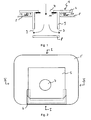
- FIG. 1 schematically illustrates a cross-sectional view of a holding plate 1 according to the invention.
- the holding plate comprises a base plate 2, a deflection device 3 and a fastening device 4.
- the base plate 2, the deflector 3 and the fastening device 4 may each consist of a plastic.
- the entire holding plate may be formed as an injection molded part.
- the base plate 2 is formed so that it can be connected to a holding device of a vacuum cleaner so that it can be held in a vacuum cleaner housing.
- FIG. 2 A plan view of a holding plate 1 connected to a vacuum cleaner filter bag 5 is shown in FIG. 2 shown.
- This holding plate 1 is in a holding device 6, which may be particularly firmly connected to the vacuum cleaner housing, plugged and is supported in this manner.
- the cross-sectional view along the line II is in FIG. 1 shown.
- the base plate 2 of the retaining plate 1 has a passage opening 7, through which an air flow during operation can enter the deflection device and then into the vacuum cleaner filter bag.
- the deflector 3 connected to the base plate 2 has a cylindrical shape.
- the Side wall of the deflector is connected at its upper end to the base plate 2 and surrounds the passage opening 7.
- the cylinder 3 forming the deflector is open at the top, so that in this way an inlet opening is formed in the deflector.
- the base plate of the cylinder is opposite to the passage opening 7 and parallel to the plane of the passage opening.
- a deflection 8 is formed in the side wall of the deflector in the side wall of the deflector two opposite outflow openings 9 are provided.
- the deflection device may alternatively also have only one outflow opening or more than two outflow openings.
- the height of the deflector can be between 1 cm and 5 cm, in particular between 2 cm and 4 cm, and the diameter between 3 cm and 9 cm, preferably 5 cm and 8 cm.
- the holding plate 1 also has a fastening device 4, which is also cylindrical in the illustrated example and surrounds the passage opening 7.
- the fastening device 4 comprises an external thread (not shown).
- On the vacuum cleaner filter bag 5 a counter attachment 10 is attached.
- This fastening counterpart device comprises, in particular, an internal thread corresponding to the external thread of the fastening device 4.
- the attachment counter-device 10 is fixedly connected to the bag wall of the vacuum cleaner filter bag 5, for example glued or welded. In this way, the holding plate 1 can be screwed to the vacuum cleaner filter bag, whereby a secure connection is achieved.
- the holding plate 1 further comprises a sealing element 11, which is a ring made of a flexible material surrounding the passage opening 7. Through this ring a plugged into the passage opening (for connection to a vacuum cleaner tube) is sealed.
- the bag wall of the vacuum cleaner filter bag for example, have a structure as shown in the EP 0 960 645 is described.
- a coarse filter layer for example from a meltblown
- a fine filter layer for example likewise from a meltblown.
- further layers may be provided in the filter structure, for example support layers and / or odor-absorbing layers.
- FIGS. 3 and 4 illustrate another embodiment of a retaining plate with a deflector. It shows FIG. 3 schematically a cross section of the holding plate, in which the deflector assumes its first position in which they, in comparison with the in FIG. 4 Having shown second position, a smaller extent perpendicular to the plane of the passage opening 7.
- the cross-sectional view in the FIGS. 3 and 4 corresponds to the cross section along the line II-II in FIG. 2 ,
- the in these FIGS. 3 and 4 Holding plate 1 shown also includes a deflector 3, which here, however, has a cuboid shape.
- the base 8 of the cuboid is arranged parallel to the plane of the passage opening 7. This base also serves to close the passage opening.
- a further sealing element 12 is provided on the base 8 of the cuboid. This serves to seal the passage opening in the first position of the closure device tight.
- the further sealing element 12 may in particular be adapted to the opening in the first sealing element 11.
- the sealing elements 11 and 12 can be made by using a continuous, i. the passage opening overlapping, sealing material is disposed in the interior of the deflector.
- This may be, for example, a closed-cell foam, into which an opening is subsequently punched during production in order to expose an inflow opening in the cuboid.
- the punched out material can then be arranged on the base 8 of the cuboid.
- a bending spring 13 which may be, for example, cambered provided.
- the spring force is a restoring force on the deflector exercised, so that these in principle their in FIG. 3 shown closed position occupies.
- the bending spring 13 may be glued, for example, with the base surface and a side surface of the cuboid.
- the spring can also be arranged in another way.
- the deflection device may be at least partially double-layered (for example with two layers of cardboard), wherein the spring is arranged between the two layers. The layers are glued together leaving a non-bonded gap for the spring; the spring itself then need not be glued to one of the layers; Alternatively, it may also be firmly connected to one or both layers only at one end.
- the sealing element 12 can penetrate into the opening of the sealing element 11 differently far in the first position of the deflecting device.
- a permanent magnet can also be provided in or on the base plate 2 and a ferromagnetic element in or on one of the side surfaces or the base surface of the deflection device.
- a return device is also formed, which allows a folding of the deflection.
- the spring 13 may be formed such that in operation of the vacuum cleaner, the force caused by a suction air flow is sufficient to bring the deflector from the first position to the second position. When you turn off the vacuum cleaner then the restoring force of the spring acts such that the passage opening is closed again.
- the fastening device 4 is a hook-and-loop fastener element.
- a corresponding Velcro counter element 10 is then arranged, so that the holding plate can be securely connected to the vacuum cleaner filter bag.
- the hook-and-loop fastener element can, for example, be glued or welded to the bag wall.
- the dimensions of the cuboid deflection devices can be, for example, 7.5 cm ⁇ 8 cm ⁇ 3 cm (width ⁇ depth ⁇ height).
- the material may be cardboard, for example.
- the deflection can be glued, for example, with a base plate made of plastic.
- the surface of the deflection device facing the base plate 2 may be coated with a plastic corresponding to the base plate so that the base plate 2 and the deflection device 3 can be welded together.
- a plastic for example polypropylene may be provided.
- outflow openings are provided in the two parallel to the plane of the side surfaces of the cuboid deflection, which in particular each occupy the entire side surface of the cuboid.
- At the edges between the baffle plate 8 and the two other side surfaces or between the two side surfaces and the top surface with the inlet opening in the deflection folding lines 14 are provided which allow a folding of the deflector to the extent of the deflector perpendicular to the plane of the passage opening out.
- part of the base area of a cuboid deflection device may be removed, so that a common outflow opening is formed by both. This can be avoided that a relatively narrow gap between the deflector and bag wall clogged during operation.
- the deflection device may be formed and / or arranged on the base plate, that they the position according to FIG. 3 occupies, if the vacuum cleaner filter bag is not held with the holding plate in the vacuum cleaner housing.
- the deflector is by contact, for example, with a housing in the position according to FIG. 4 brought.
- the two side walls welded together along the edge are at least partially moved apart in this way, so that the volume increases in the interior. This also allows a flat bag with a side gusset in an upright vacuum cleaner use.
- the deflector may be formed by a strip of material from a film or a non-woven fabric.
- a holding plate 1 with such a flexible deflecting device 3 is in FIG. 5 shown schematically.
- Such a Strip can be connected at its two ends to the base plate so that it hangs in front of the passage opening 7. In this way, two outflow openings are also formed.
- the film of the deflector 3 made of the same material as the base plate 2 and be injected in one operation.
- the film can be made of a different material and sprayed in a second operation to a base plate (2K injection molding).
- the production can be carried out by means of insert molding or subsequent gluing or welding. If a thermoplastic elastomer is used, the sealing member 11 may be formed simultaneously.
- FIG. 6 Another embodiment is shown schematically in a cross-sectional view in FIG. 6 shown.
- the deflector 3 can be folded in the manner of a concertina.
- the two left and right side surfaces each have in their middle a parallel to the base surface extending fold line 14 on which the side surface can be kinked.
- a permanent magnet (not shown) in or on the base plate 2 and a ferromagnetic element (not shown) may be provided in or on one of the side surfaces or the base of the deflector 3.
- a ferromagnetic element may be provided in or on one of the side surfaces or the base of the deflector 3.
- a suction air flow acts on the base of the deflection a force to move them in the direction of the base plate.
- the deflection device may also have a wedge-shaped or wedge-like shape.
- the deflector may be formed like a reduced filter bag with block bottom, but without its own holding plate or the like.
- the block bottom is connected to the inlet opening with the bag facing side of the holding plate; in the two narrow side surfaces of the deflector two holes are cut at the wedge tip as discharge openings.
- the incoming air is formed by the wide side surfaces and the spiral fold with the connecting edge or in the region of the Wickelfalzes Surface deflected by the discharge opening.
- the advantage of this shape of the deflector is that it can also be folded in a simple manner. Further designs of the deflection device are also possible.
Description
Die Erfindung betrifft eine Halteplatte für einen Staubsaugerfilterbeutel, die an einer Halteeinrichtung in einem Staubsaugergehäuse zum Haltern des Staubsaugerfilterbeutels anbringbar ist.The invention relates to a holding plate for a vacuum cleaner filter bag, which is attachable to a holding device in a vacuum cleaner housing for holding the vacuum cleaner filter bag.
In Staubsaugern, die mit Staubsaugerfilterbeuteln arbeiten, werden letztere im Gehäuse des Staubsaugers angeordnet. Hierfür ist bei herkömmlichen Staubsaugerfilterbeuteln eine Halteplatte am Filterbeutel vorgesehen, die an einer Halteeinrichtung im Staubsaugergehäuse angebracht wird, so dass auf diese Weise der Staubsaugerfilterbeutel im Gehäuse gehaltert wird. Derartige Halteplatten sind bei herkömmlichen Staubsaugerfilterbeuteln häufig mit dem Filtermaterial des Beutels verklebt oder verschweißt. Da sich die Halteeinrichtungen verschiedener Staubsaugertypen im allgemeinen unterscheiden, muss für jeden unterschiedlichen Staubsaugertyp ein entsprechender Staubsaugerfilterbeutel mit passender Halteplatte hergestellt und gekauft werden.In vacuum cleaners, which work with vacuum cleaner filter bags, the latter are arranged in the housing of the vacuum cleaner. For this purpose, in conventional vacuum cleaner filter bags, a holding plate is provided on the filter bag, which is attached to a holding device in the vacuum cleaner housing, so that in this way the vacuum cleaner filter bag is held in the housing. Such holding plates are often glued or welded in conventional vacuum cleaner filter bags with the filter material of the bag. Since the holding devices of different types of vacuum cleaner generally differ, for each different type of vacuum cleaner, a corresponding vacuum cleaner filter bag must be made and purchased with matching holding plate.
Alternativ besteht eine Möglichkeit darin, Adapterplatten bereitzustellen, die jeweils auf eine Halteeinrichtung eines bestimmten Staubsaugers abgestimmt ist. Diese Adapterplatte ist derart ausgebildet, dass sie mit einem universellen Staubsaugerfilterbeutel lösbar verbunden werden kann. Auf diese Weise genügt es, verschiedene Adapterplatten für die unterschiedlichen Staubsauger bzw. ihre Halteeinrichtungen bereitzustellen, wobei allerdings ein einheitlicher Filterbeutel verwendet werden kann. Solche Adapterplatten sind beispielsweise aus der
Derartige aus dem Stand der Technik bekannte Halteplatten werden mit herkömmlichen Filterbeuteln verbunden. In den letzten Jahren wurden verschiedene Anstrengungen unternommen, die Standzeit herkömmlicher Filterbeutel zu verbessern. Die Weiterentwicklungen richteten sich dabei darauf, verschiedene Materiallagen in geeigneter Form zusammenzustellen.Such known from the prior art holding plates are connected to conventional filter bags. In recent years, various efforts have been made to improve the service life of conventional filter bags. The further developments were aimed at putting together different material layers in a suitable form.
So ist beispielsweise aus der
Aus der
Die
Die
Aus der
Schließlich offenbart die
Es ist Aufgabe der vorliegenden Erfindung, eine Möglichkeit bereitzustellen, mit der die Standzeit eines Filterbeutels bei sehr guten Filtrationseigenschaften erhöht werden kann.It is an object of the present invention to provide a way by which the service life of a filter bag can be increased with very good filtration properties.
Diese Aufgabe wird gelöst durch eine Halteplatte gemäß Anspruch 1.This object is achieved by a holding plate according to claim 1.
Erfindungsgemäß wird eine Halteplatte für einen Staubsaugerfilterbeutel bereitgestellt, die an einer Halteeinrichtung in einem Staubsaugergehäuse zum Haltern des Staubsaugerfilterbeutels anbringbar ist, mit einer Grundplatte, in der eine Durchtrittsöffnung für einen Luftstrom ausgebildet ist,
einer mit der Grundplatte verbundenen Befestigungseinrichtung zum zerstörungsfrei lösbaren Verbinden der Halteplatte mit einem Staubsaugerfilterbeutel, und
einer die Durchtrittsöffnung wenigstens teilweise umgebenden Ablenkeinrichtung, die mit der Grundplatte verbunden und derart ausgebildet ist, dass sie nach dem Verbinden der Halteplatte mit einem Staubsaugerfilterbeutel wenigstens teilweise im Beutelinnern angeordnet ist und ein durch die Durchtrittsöffnung in die Ablenkeinrichtung eintretender Luftstrom in der Ablenkeinrichtung ablenkbar ist
wobei die Ablenkeinrichtung wenigstens eine der Durchtrittsöffnung gegenüberliegende, vorzugsweise plane, Ablenkfläche umfasst; und
wobei die wenigstens eine Ablenkfläche eine größere Fläche als die Fläche der Durchtrittsöffnung aufweist.According to the invention a holding plate for a vacuum cleaner filter bag is provided, which is attachable to a holding device in a vacuum cleaner housing for holding the vacuum cleaner filter bag, with a base plate in which a passage opening is formed for an air flow,
a fastening device connected to the base plate for non-destructively detachable connection of the retaining plate to a vacuum cleaner filter bag, and
a deflector at least partially surrounding the deflector, which is connected to the base plate and is formed so that it is at least partially disposed in the bag interior after connecting the holding plate with a vacuum cleaner filter bag and an entering through the passage opening in the deflector air flow in the deflector is deflected
wherein the deflecting device comprises at least one, preferably flat, deflection surface opposite the passage opening; and
wherein the at least one deflection surface has a larger area than the area of the passage opening.
Überraschenderweise wurde festgestellt, dass eine solche Halteplatte die Standzeit eines Staubsaugerfilterbeutels signifikant erhöht, Insbesondere wurde festgestellt, dass der sich in einem Filterbeutel bildende Filterkuchen erheblich zum Filtrationsverhalten des Filterbeutels beiträgt. Durch die als Teil der Halteplatte vorgesehene Ablenkeinrichtung wird ein in dieser Ablenkeinrichtung eintretender Luftstrom, der auf diese Weise auch in den Beutel eintritt, abgelenkt, so dass die mitgeführten Partikel gleichmäßig im Beutelinnern verteilt werden und folglich eine gleichmäßige Verteilung des sich bildenden Filterkuchens und damit eine erhöhte Standzeit erhalten wird. Hierfür kann die Ablenkeinrichtung insbesondere wenigstens eine Ausströmöffnung aufweisen, die nach dem Verbinden der Halteplatte mit dem Staubsaugerfilterbeutel im Beutelinnern angeordnet ist, so dass ein in der Ablenkeinrichtung abgelenkter Luftstrom in das Beutelinnere strömen kann.Surprisingly, it was found that such a holding plate significantly increases the service life of a vacuum cleaner filter bag. In particular, it has been found that the filter cake forming in a filter bag contributes significantly to the filtration behavior of the filter bag. As a result of the deflection device provided as part of the retaining plate, an air flow entering this deflection device, which thus enters the bag, is deflected, so that the entrained particles are evenly distributed in the bag interior and consequently a uniform distribution of the forming filter cake and thus a increased service life is obtained. For this purpose, the deflecting device may in particular comprise at least one outflow opening, which is arranged in the bag interior after connecting the holding plate to the vacuum cleaner filter bag, so that a deflected in the deflector air flow can flow into the bag interior.
Durch die wenigstens eine der Durchtrittsöffnung gegenüberliegende Ablenk- oder Prallfläche lässt sich insbesondere die Geschwindigkeit der Partikel in geeigneter Weise reduzieren. Der Abstand bzw. der mittlere Abstand einer derartigen Ablenkfläche von der Durchtrittsöffnung kann insbesondere von der Größe und Form der Staubsaugerfilterbeutel oder Staubsauger abhängen, für die eine derartige Halteplatte vorgesehen sein soll.The at least one deflection or baffle surface opposite the passage opening can in particular reduce the velocity of the particles in a suitable manner. The distance or the average distance of such a deflection of the Passage opening may depend in particular on the size and shape of the vacuum cleaner filter bag or vacuum cleaner, for which such a holding plate should be provided.
Durch die größere Fläche der Ablenkfläche als die Fläche der Durchtrittsöffnung wird weitgehend vermieden, dass ein Luftstrom lediglich um die Ablenkfläche herumgelenkt wird und danach aber mit im Wesentlichen unveränderter Strömungsgeschwindigkeit auf eine der Einlassöffnung eines Staubsaugerfilterbeutels gegenüberliegende Seite trifft. Jede Ablenkfläche kann eine Fläche von 15 bis 100 cm2, insbesondere 40 bis 60 cm2, aufweisen.Due to the larger area of the deflection surface than the surface of the passage opening is largely avoided that an air flow is deflected only around the deflecting surface and then but with substantially unchanged flow velocity to one of the inlet opening of a vacuum cleaner filter bag meets opposite side. Each deflection surface may have an area of 15 to 100 cm 2 , in particular 40 to 60 cm 2 .
Da die Ablenkeinrichtung weiterhin als Teil einer Halteplatte ausgebildet ist, die außerdem eine Befestigungseinrichtung zum zerstörungsfrei lösbaren Verbinden mit einem Staubsaugerfilterbeutel aufweist, ausgebildet ist, wird auf diese Weise ein Nachrüstelement bereitgestellt, das mit verschiedensten Staubsaugerfilterbeuteln verbunden werden kann, soweit diese zur Verbindung mit der Halteplatte geeignet ausgebildet sind. Dies erlaubt es weiterhin, dass die Staubsaugerfilterbeutel selbst nur mit geringem Aufwand hergestellt werden können, da die Ablenkeinrichtung auf Seiten der Halteplatte bereitgestellt wird. Dies reduziert zum einen die Komplexität des Herstellungsverfahrens der Filterbeutel; zum anderen lassen sich die Filterbeutel zu kleineren Abmessungen zusammenfalten und/oder verpacken.Further, since the baffle is formed as part of a retainer plate which also has attachment means for non-destructively detachable connection to a vacuum cleaner filter bag, a retrofit member is provided in this manner which can be connected to a variety of vacuum cleaner filter bags as far as they are for connection to the retainer plate are formed suitable. This further allows that the vacuum cleaner filter bag itself can be made only with little effort, since the deflector is provided on the side of the holding plate. This, on the one hand, reduces the complexity of the manufacturing process of the filter bags; on the other hand, the filter bags can be folded to smaller dimensions and / or pack.
Bei der Ablenkeinrichtung der Halteplatte tritt Luft mit einer Strömungsrichtung (Eintrittsströmungsrichtung) durch eine Durchtrittsöffnung in der Grundplatte in die Ablenkeinrichtung ein und wird in dieser abgelenkt, so dass eine Änderung der Strömungsrichtung in der Ablenkeinrichtung bzgl. der Strömungsrichtung an der Durchtrittsöffnung eintritt. Unter der Strömungsrichtung des Luftstroms oder Luftströmungsrichtung ist die Hauptströmungsrichtung der Luft gemeint, die im Allgemeinen parallel einer Wandung, beispielsweise eines Staubsaugerrohrs oder Stutzens, verläuft. Im Betrieb eines Staubsaugers ergibt sich eine derartige Hauptströmungsrichtung an jedem Punkt durch ein Staubsaugerrohr bis in den Beutel, auch wenn an einzelnen Stellen ggf. Verwirbelungen auftreten können.In the deflection of the holding plate enters air with a flow direction (inlet flow direction) through a passage opening in the base plate in the deflector and is deflected in this, so that a change in the flow direction in the deflector with respect to the flow direction at the passage opening occurs. By flow direction of the air flow or air flow direction is meant the main flow direction of the air, which runs generally parallel to a wall, for example a vacuum cleaner pipe or nozzle. During operation of a vacuum cleaner, such a main flow direction results at any point through a vacuum cleaner tube into the bag, even if turbulence may possibly occur at individual points.
Die Ablenkeinrichtung kann insbesondere mit der Grundplatte nicht-zerstörungsfrei lösbar verbunden sein.The deflection device can in particular be non-destructively releasably connected to the base plate.
Die Befestigungseinrichtung kann zum Ausbilden einer kraftschlüssigen oder einer formschlüssigen Verbindung ausgebildet sein. Insbesondere kann die Befestigungseinrichtung zum Ausbilden einer Schraub-, Keil-, Stift-, Klett- oder Schnappverbindung ausgebildet sein. Diese Varianten erlauben eine besonders günstige und einfache Verbindung der Halteplatte mit einem Filterbeutel.The fastening device can be designed to form a non-positive or a positive connection. In particular, the fastening device can be designed to form a screw, wedge, pin, Velcro or snap connection. These variants allow a particularly favorable and simple connection of the holding plate with a filter bag.
Die Ablenkeinrichtung kann zum Aufteilen des Luftstroms in wenigstens zwei Teilströme mit unterschiedlichen Strömungsrichtungen ausgebildet sein.The deflection device can be designed to split the air flow into at least two partial flows with different flow directions.
Durch eine derartige Aufteilung in zwei oder mehr Teilströme wird eine noch gleichmäßigere Verteilung des Filterkuchens erreicht. Außerdem ist die Zahl der Partikel pro Teilchenstrom im Vergleich mit dem eintretenden Luftstrom verringert, was die Belastung der Wände des mit einer solchen Halteplatte verbundenen Staubsaugerfilterbeutels durch die einzelnen Teilströme reduziert.By such a division into two or more streams even more even distribution of the filter cake is achieved. In addition, the number of particles per particle flow is reduced in comparison with the incoming air flow, which reduces the load on the walls of the vacuum cleaner filter bag connected to such a holding plate by the individual partial flows.
Die wenigstens eine Ablenkfläche kann in einem vorherbestimmten Winkel relativ zur Ebene der Durchtrittsöffnung, insbesondere parallel zur Ebene der Durchtrittsöffnung, angeordnet sein.The at least one deflection surface can be arranged at a predetermined angle relative to the plane of the passage opening, in particular parallel to the plane of the passage opening.
Durch eine geeignete Wahl des Winkels kann die Ablenkung des Luftstroms an unterschiedliche Parameter wie Einströmwinkel, Geometrie oder Dimensionierung eines Staubsaugergehäuses und/oder -beutels angepasst und optimiert werden. Bei einer parallel zur Ebene der Durchtrittsöffnung angeordneten Ablenkfläche wird eine senkrecht zur Ebene der Durchtrittsöffnung einströmende Luftströmung um etwa 90° umgelenkt oder abgelenkt, was eine günstige Verteilung der Partikel und des daraus resultierenden Filterkuchens in den Filterbeutel zur Folge hat.By a suitable choice of the angle, the deflection of the air flow to different parameters such as inlet angle, geometry or dimensioning of a vacuum cleaner housing and / or bag can be adjusted and optimized. In a parallel to the plane of the passage opening arranged deflection perpendicular to the plane of the passage opening air flow is deflected or deflected by about 90 °, which has a favorable distribution of the particles and the resulting filter cake in the filter bag result.
Eine der Durchtrittsöffnung gegenüberliegende Ablenkfläche kann insbesondere von dieser einen Abstand bzw. einen mittleren Abstand von zwischen 0,5 cm und 5 cm, insbesondere 2,5 cm bis 4 cm, aufweisen.A deflection surface opposite the passage opening can have a distance or an average distance of between 0.5 cm and 5 cm, in particular 2.5 cm to 4 cm, in particular from the latter.
Die Ablenkeinrichtung kann insbesondere zum Aufteilen des Luftstroms in wenigstens zwei Teilströme mit einander entgegengesetzten Strömungsrichtungen ausgebildet sein. Einander entgegengesetzte Strömungsrichtungen bedeutet, dass beide Strömungsrichtungen eine Komponente in der Ebene senkrecht zur Strömungsrichtung aufweisen, mit der ein Luftstrom durch die Durchtrittsöffnung in die Ablenkeinrichtung eintritt, d.h. also eine Komponente senkrecht zur Eintrittsströmungsrichtung, wobei die Komponenten einen Winkel von etwa 180° einschließen und wobei die Komponenten in dieser Ebene jeweils größer sind als die entsprechende Komponente parallel zur Eintrittsströmungsrichtung. Dies bedeutet, dass (in vektorieller Betrachtung der Strömungsrichtung) die zwei Teilströme in der senkrechten Projektion in die Ebene senkrecht zur Eintrittsströmungsrichtung antiparallel angeordnet sind.The deflection device can be designed, in particular, for dividing the air flow into at least two partial flows with opposite directions of flow. Opposing flow directions means that both flow directions have a component in the plane perpendicular to the flow direction, with which an air flow enters the deflection device through the passage opening, ie a component perpendicular to the inlet flow direction, wherein the components enclose an angle of approximately 180 ° and the components in this plane are each larger than the corresponding component parallel to the inlet flow direction. This means that (in vectorial view of the flow direction), the two partial flows are arranged in anti-parallel in the vertical projection in the plane perpendicular to the inlet flow direction.
Die Ablenkeinrichtung kann derart ausgebildet sein, dass ein in die Ablenkeinrichtung tretender Luftstrom in der Ablenkeinrichtung verglichen mit der Luftströmung an der Durchtrittsöffnung um wenigstens 45°, vorzugsweise wenigstens 60°, weiter bevorzugt wenigstens 80°, ablenkbar ist.The deflecting device can be designed such that an air flow passing into the deflecting device in the deflecting device can be deflected by at least 45 °, preferably at least 60 °, more preferably at least 80 °, compared to the air flow at the passage opening.
Dies bedeutet, dass die Luftströmungsrichtung beim Austreten aus der Ablenkeinrichtung mit der Strömungsrichtung an der Durchtrittsöffnung einen Winkel von wenigstens 45° einschließt. Damit ergibt sich eine besonders vorteilhafte Luftströmungsrichtung in einen Staubsaugerfilterbeutel.This means that the air flow direction forms an angle of at least 45 ° when exiting the deflecting device with the flow direction at the passage opening. This results in a particularly advantageous air flow direction in a vacuum cleaner filter bag.
Die Ablenkeinrichtung der zuvor beschriebenen Halteplatten kann in einer Weiterbildung zwei trapezförmige oder rechteckige Ablenkflächen aufweisen, die ausgehend von der Durchtrittsöffnung, keilförmig aufeinander zulaufen und an einer der Durchtrittsöffnung gegenüberliegenden Verbindungskante miteinander verbunden sind.In one development, the deflection device of the retaining plates described above can have two trapezoidal or rectangular deflection surfaces which, starting from the passage opening, run in a wedge shape towards one another and are connected to one another at a connecting edge opposite the passage opening.
Insbesondere kann eine derartige Ablenkeinrichtung weiterhin an wenigstens einem Ende der Verbindungskante eine Ausströmöffnung und einen die Durchtrittsöffnung umgebenden und mit der Grundplatte verbundenen Bereich, der nach Art eines Klotzbodens ausgebildet ist und eine Einströmöffnung aufweist, umfassen.In particular, such a deflecting device may further comprise at at least one end of the connecting edge an outflow opening and a region surrounding the passage opening and connected to the base plate, which is designed in the manner of a block bottom and has an inflow opening.
Auf diese Weise können aus dem Staubsaugerbeutelbereich bekannte Klotzbodenformen, wie sie beispielsweise in der
Die Ablenkeinrichtung der zuvor beschriebenen Halteplatten kann in einer alternativen Weiterbildung die Form eines Quaders aufweisen, der in der die Durchtrittsöffnung umgebenden und mit der Grundplatte verbundenen Deckfläche eine Einströmöffnung und in wenigstens einer Seitenfläche eine Ausströmöffnung aufweist.The deflection device of the retaining plates described above may, in an alternative development, have the shape of a cuboid which has an inflow opening in the cover surface surrounding the passage opening and connected to the base plate and an outflow opening in at least one side face.
Durch die Quaderform wird ein stabiler Aufbau der Ablenkeinrichtung erzielt, wobei gleichzeitig eine geeignete Ablenk- oder Prallfläche zur Umlenkung des Luftstroms durch die der Einströmöffnung gegenüberliegende Grundfläche des Quaders gebildet wird.The cuboid shape achieves a stable construction of the deflection device, with a suitable deflecting or baffle surface being simultaneously formed for deflecting the air flow through the base surface of the cuboid opposite the inflow opening.
Alternativ kann die Grundfläche des Quaders wenigstens einen Durchbruch aufweisen, der mit einem Durchbruch in einer Seitenfläche eine Ausströmöffnung bildet. Damit bildet nicht mehr die gesamte Grundfläche sondern nur noch ein Teil davon eine Ablenkfläche. Eine derartige Konfiguration ist insbesondere dann von Vorteil, wenn im Betrieb eines Staubsaugerfilterbeutels der Abstand zwischen der Seitenfläche der quaderförmigen Ablenkeinrichtung und der Beutelwand aufgrund der Geometrie des Beutels und des Staubsaugergehäuses gering ist (beispielsweise bei amerikanischen Upright-Staubsaugern), so dass bei einer Ausströmöffnung nur in einer Seitenwand ein Verstopfungsproblem auftreten kann.Alternatively, the base surface of the cuboid may have at least one opening, which forms an outflow opening with an opening in a side surface. Thus, not the entire base area but only a part of it forms a deflection. Such a configuration is particularly advantageous if during operation of a vacuum cleaner filter bag, the distance between the side surface of the cuboid deflector and the bag wall due to the geometry of the bag and the vacuum cleaner housing is low (for example, in American upright vacuum cleaners), so that at an outflow only in a sidewall a clogging problem may occur.
Dabei kann insbesondere jede Ausströmöffnung im wesentlichen die gesamte Breite der Seitenfläche des Quaders einnehmen. Damit wird vermieden, dass sich im Betrieb der Halteplatte in einer Ecke des Quaders eingesaugte Staubpartikel ansammeln.In this case, in particular, each outflow opening can occupy substantially the entire width of the side surface of the cuboid. This avoids that in the operation of the holding plate in a corner of the cuboid sucked in dust particles accumulate.
Bei einer in Form eines Quaders vorgesehenen Ablenkeinrichtung können insbesondere wenigstens zwei gegenüberliegende Ausströmöffnungen vorgesehen sein.In the case of a deflection device provided in the form of a cuboid, in particular at least two opposite outflow openings can be provided.
Durch diese wenigstens zwei gegenüberliegenden Ausströmöffnungen wird einerseits erreicht, dass ein Luftstrom in zwei Teilströme aufgeteilt wird, und andererseits diese zwei Teilströme entgegengesetzte Richtungen aufweisen, was insgesamt zu einer sehr homogenen Verteilung eines Filterkuchens in einem Staubsaugerfilterbeutel führt.By means of these at least two opposite outflow openings, on the one hand, it is achieved that an air stream is divided into two sub-streams, and, on the other hand, these two sub-streams have opposite directions, resulting overall in a very homogeneous distribution of a filter cake in a vacuum cleaner filter bag.
Die zuvor beschriebenen Halteplatten können eine Ablenkeinrichtung aufweisen, die derart ausgebildet ist, dass sie in einer ersten Stellung eine im Vergleich zu einer zweiten Stellung verringerte Ausdehnung senkrecht zur Ebene der Durchtrittsöffnung aufweist.The retaining plates described above may have a deflection device, which is designed in such a way that, in a first position, it has a reduced extent, compared to a second position, perpendicular to the plane of the passage opening.
Durch die kleinere Ausdehnung in der zweiten Stellung lässt sich die Halteplatte in eine sehr kompakte Form bringen. Damit kann die Halteplatte in vorteilhafter Form verpackt und transportiert werden. Vorzugsweise kann die Ablenkreinrichtung in der ersten Stellung im Wesentlichen flach ausgebildet sein.Due to the smaller extent in the second position, the holding plate can be brought into a very compact form. Thus, the holding plate can be packaged and transported in an advantageous manner. Preferably, the deflection device may be formed substantially flat in the first position.
Gemäß einer Weiterbildung kann die Ablenkeinrichtung derart ausgebildet sein, dass sie die erste Stellung einnimmt, wenn die Halteplatte nicht von der Halteeinrichtung gehaltert wird, und dass sie in die zweite Stellung bringbar ist, wenn der Staubsaugerfilterbeutel von der Halteeinrichtung gehaltert wird.According to a development, the deflecting device may be designed such that it assumes the first position when the holding plate is not supported by the holding device, and that it can be brought into the second position when the vacuum cleaner filter bag is held by the holding device.
Wenn die Halteeinrichtung in einer festen Stellung in einem Staubsauger angebracht ist, kann die Ablenkeinrichtung so bereits beim Anbringen der Halteplatte an der Halteeinrichtung in die zweite Stellung gebracht werden. Beim Entfernen aus der Halteeinrichtung wird die Ablenkeinrichtung wieder in die erste Stellung zurückkehren.If the holding device is mounted in a fixed position in a vacuum cleaner, the deflecting device can thus be brought to the second position already when attaching the holding plate to the holding device. Upon removal from the fixture, the deflector will return to the first position.
Wenn die Halteeinrichtung beweglich, beispielsweise mittels eines Gelenks, an dem Staubsauger angebracht ist, um ein Wechseln des Staubsaugerfilterbeutels durch Herausklappen der Halteeinrichtung aus dem Staubsauger zu erleichtern, kann die Ablenkeinrichtung in die zweite Stellung gebracht werden, wenn die Halteeinrichtung in die Stellung gebracht wird, die sie während des Betriebs des Staubsaugers einnimmt. Wenn die Halteeinrichtung zum Entfernen des Staubsaugerbeutels aus dem Staubsauger geklappt wird, kehrt die Ablenkeinrichtung selbsttätig in die erste Stellung zurück.If the holding device is movably attached to the vacuum cleaner, for example by means of a hinge, to facilitate changing the vacuum cleaner filter bag by folding out the holding device from the vacuum cleaner, the deflecting device can be brought into the second position when the holding device is brought into position, which it occupies during operation of the vacuum cleaner. When the holding device for removing the vacuum cleaner bag is folded out of the vacuum cleaner, the deflector automatically returns to the first position.
Alternativ kann die Ablenkeinrichtung auch durch ein staubsaugerseitig vorgesehenes Element in die zweite Stellung und durch dieses Element wieder in die erste Stellung gebracht werden. Ein derartiges staubsaugerseitig vorgesehenes Element kann beispielsweise derart ausgebildet sein, dass es sich beim Anschalten des Staubsaugers so bewegt, dass die Ablenkeinrichtung in die zweite Stellung gebracht wird; beim Ausschalten erfolgt dann eine umgekehrte Bewegung, die es ermöglicht, dass die Ablenkeinrichtung wieder in die erste Stellung zurückkehrt.Alternatively, the deflector can be brought by a vacuum cleaner side provided element in the second position and by this element again in the first position. Such a vacuum cleaner side provided element may for example be designed such that it moves when turning on the vacuum cleaner so that the deflector is brought into the second position; when switching off then takes place a reverse movement, which makes it possible that the deflector returns to the first position.
Gemäß einer anderen Alternative kann die Ablenkeinrichtung derart ausgebildet sein, dass sie durch einen Saugluftstrom von der ersten Stellung in die zweite Stellung bringbar ist. Auf diese Weise wird es ermöglicht, dass die Halteplatte mit ihrer Ablenkeinrichtung durch den auf Grund des durch das Ansaugen von Luft im Beutel entstehenden Unterdrucks im Staubsauger in ihre Betriebsstellung übergeht, in der die Ablenkeinrichtung ihre Ablenkeinrichtung erfüllt.According to another alternative, the deflection device may be designed such that it can be brought from the first position to the second position by a suction air flow. In this way, it is possible that the holding plate with its deflector passes by the resulting due to the suction of air in the bag negative pressure in the vacuum cleaner in its operating position in which the deflector fulfills its deflection.
In den zuvor beschriebenen Halteeinrichtungen kann die Ablenkeinrichtung ein Rückstellelement, insbesondere ein Federelement, umfassen, das auf einen Teil der Ablenkeinrichtung eine Rückstellkraft derart ausübt, dass die Ablenkeinrichtung von der zweiten Stellung in die erste Stellung bringbar ist.In the holding devices described above, the deflecting device may comprise a restoring element, in particular a spring element, which exerts a restoring force on a part of the deflecting device in such a way that the deflecting device can be brought from the second position into the first position.
Ein solches Rückstellelement ermöglicht, dass die Ablenkeinrichtung bei Nachlassen des Saugluftstroms, beispielsweise wenn der Staubsauger ausgeschaltet wird, aus der zweiten Stellung wieder in die erste Stellung mit verringerter Ausdehnung senkrecht zur Ebene der Durchtrittsöffnung übergeht.Such a return element allows the deflector on release of the suction air flow, for example, when the vacuum cleaner is switched from the second position back to the first position with reduced extension perpendicular to the plane of the passage opening.
Die Ablenkeinrichtung kann Falzlinien oder Filmscharniere aufweisen, so dass die Ablenkeinrichtung von der ersten oder zweiten Stellung in die zweite bzw. erste Stellung bringbar ist. Derartige Falzlinien oder Filmscharniere erlauben das gewünschte Zusammenlegen bzw. -falten in einfacher und zuverlässiger Weise.The deflection device can have fold lines or film hinges, with the result that the deflection device can be brought from the first or second position into the second or first position. Such fold lines or film hinges allow the desired folding or folding in a simple and reliable manner.
Alternativ zu den beschriebenen Weiterbildungen kann die Ablenkeinrichtung allerdings auch starr ausgebildet sein, so dass ein Zusammenlegen nicht möglich ist.As an alternative to the further developments described, however, the deflecting device can also be rigid, so that collapsing is not possible.
Bei den zuvor beschriebenen Halteplatten kann die Ablenkeinrichtung weiterhin zum Verschließen der Durchtrittsöffnung ausgebildet sein.In the case of the retaining plates described above, the deflecting device can furthermore be designed to close the passage opening.
Damit wird ein zusätzliches Verschlusselement, das häufig auch noch an einer Halteplatte eines Staubsaugerfilterbeutels vorgesehen ist, vermieden, was den Aufbau und die Herstellung der Halteplatte wesentlich vereinfacht.Thus, an additional closure element, which is often also provided on a holding plate of a vacuum cleaner filter bag, avoided, which greatly simplifies the construction and manufacture of the holding plate.
Insbesondere kann die Ablenkeinrichtung, wie bereits zuvor beschrieben, ein Federelement umfassen, das auf einen Teil der Ablenkeinrichtung eine Rückstellkraft ausübt, um die Durchtrittsöffnung zu verschließen.In particular, as already described above, the deflection device may comprise a spring element which exerts a restoring force on a part of the deflection device in order to close the passage opening.
Die zuvor beschriebenen Halteplatten können ein Dichtungselement, insbesondere zum Abdichten der Durchtrittöffnung, umfassen.The holding plates described above may comprise a sealing element, in particular for sealing the passage opening.
Mit einem derartigen Dichtungselement kann insbesondere die Durchtrittsöffnung um einen im Betrieb des Staubsaugers eingeführten Stutzen abgedichtet werden.With such a sealing element, in particular, the passage opening can be sealed by a nozzle introduced during operation of the vacuum cleaner.
Das Dichtungselement kann insbesondere mit der Grundplatte an ihrer der Ablenkeinrichtung zugewandten Seite verbunden und/oder innerhalb der Ablenkeinrichtung angeordnet sein. Damit lässt sich die Gefahr einer Beschädigung des Dichtungselements verringern.The sealing element can in particular be connected to the base plate on its side facing the deflection device and / or arranged inside the deflection device. This reduces the risk of damaging the sealing element.
Das Dichtungselement kann insbesondere Gummi, ein Elastomer, eine Folie oder einen Schaum, insbesondere einen geschlossenzelligen Schaum, umfassen. Beispielsweise kann die Halteplatte einen an die Grundplatte gespritzten Schaum umfassen, der an der der Ablenkeinrichtung zugewandten Seite die Durchtrittsöffnung umgebend derart vorgesehen ist, dass er beim Verbinden der Halteplatte mit einem Staubsaugerfilterbeutel in die Durchtrittsöffnung eintritt.The sealing element may in particular comprise rubber, an elastomer, a foil or a foam, in particular a closed-cell foam. For example, the holding plate may comprise a sprayed onto the base plate foam, which is provided on the side facing the deflector surrounding the passage opening so that it enters the passage opening when connecting the holding plate with a vacuum cleaner filter bag.
Die Grundplatte der Halteplatte kann insbesondere Pappe oder einen Kunststoff umfassen. Die Ablenkeinrichtung kann einen Kunststoff, ein trocken- oder nassgelegtes Vlies oder Papier, insbesondere Pappe, oder eine Folie umfassen. Sowohl für die Ablenkeinrichtung als auch für die Grundplatte sind auch andere Materialien möglich, dabei ist aber eine ausreichende Steifigkeit des Materials von Vorteil. Auch die Befestigungseinrichtung kann insbesondere einen Kunststoff oder Pappe umfassen. Die Grundplatte und die Ablenkeinrichtung und ggf. die Befestigungseinrichtung können das gleiche Material umfassen.The base plate of the holding plate may in particular comprise cardboard or a plastic. The deflection device may comprise a plastic, a dry or wet-laid nonwoven or paper, in particular cardboard, or a film. Both for the deflection and for the base plate other materials are possible, but it is sufficient rigidity of the material beneficial. The fastening device may in particular comprise a plastic or cardboard. The base plate and the deflection device and, if necessary, the fastening device may comprise the same material.
Es wird weiterhin ein Staubsaugerfilterbeutel zum Verbinden mit einer der zuvor beschriebenen Halteplatten offenbart mit einer Befestigungsgegeneinrichtung, die zum Zusammenwirken mit der Befestigungseinrichtung ausgebildet ist, so dass die Halteplatte mit dem Staubsaugerfilterbeutel verbindbar ist.There is further disclosed a vacuum cleaner filter bag for connection to one of the above-described holding plates with a counter attachment means adapted to cooperate with the attachment means, such that the holding plate is connectable to the vacuum cleaner filter bag.
Weitere Merkmale und Vorteile der Erfindung werden nachfolgend an Hand der Figuren näher erläutert. Hierbei zeigt:
- Figur 1
- eine Querschnittsansicht eines ersten Beispiels einer Halteplatte;
Figur 2- eine Draufsicht auf eine Halteplatte;
Figur 3- eine Halteplatte mit einer zusammenlegbaren Ablenkeinrichtung in einer ersten Stellung;
Figur 4- die
Halteplatte nach Figur 3 mit der Ablenkeinrichtung in der zweiten Stellung; Figur 5- eine Halteplatte mit einer flexiblen Ablenkeinrichtung;
Figur 6- ein weiteres Beispiel einer zusammenlegbaren Halteplatte.
- FIG. 1
- a cross-sectional view of a first example of a holding plate;
- FIG. 2
- a plan view of a holding plate;
- FIG. 3
- a retainer plate having a collapsible deflector in a first position;
- FIG. 4
- the holding plate after
FIG. 3 with the deflector in the second position; - FIG. 5
- a holding plate with a flexible deflection device;
- FIG. 6
- another example of a collapsible retaining plate.
Die Grundplatte 2, die Ablenkeinrichtung 3 und die Befestigungseinrichtung 4 können jeweils aus einem Kunststoff bestehen. Insbesondere kann die gesamte Halteplatte als ein Spritzgussteil ausgebildet sein. Die Grundplatte 2 ist derart ausgebildet, dass sie mit einer Halteeinrichtung eines Staubsaugers verbunden werden kann, so dass sie in einem Staubsaugergehäuse gehaltert werden kann.The
Eine Draufsicht auf eine mit einem Staubsaugerfilterbeutel 5 verbundene Halteplatte 1 ist in
Die Grundplatte 2 der Halteplatte 1 weist eine Durchtrittsöffnung 7 auf, durch die ein Luftstrom im Betrieb in die Ablenkeinrichtung und dann in den Staubsaugerfilterbeutel treten kann. Die mit der Grundplatte 2 verbundene Ablenkeinrichtung 3 hat eine Zylinderform. Die Seitenwandung der Ablenkeinrichtung ist an ihrem oberen Ende mit der Grundplatte 2 verbunden und umgibt die Durchtrittsöffnung 7. Der die Ablenkeinrichtung 3 bildende Zylinder ist nach oben offen, so dass auf diese Weise eine Eintrittsöffnung in die Ablenkeinrichtung gebildet wird.The
Die Grundplatte des Zylinders liegt gegenüber der Durchtrittsöffnung 7 und parallel zur Ebene der Durchtrittsöffnung. Durch diese Grundplatte wird eine Ablenkfläche 8 gebildet. In der Seitenwandung der Ablenkeinrichtung sind zwei gegenüberliegende Ausströmöffnungen 9 vorgesehen. Durch eine derartige Konfiguration der Ablenkeinrichtung wird ein durch die Durchtrittsöffnung 7 eintretender Luftstrom in zwei Teilströme aufgeteilt, die relativ zur Strömungsrichtung an der Durchtrittsöffnung um etwa 90° abgelenkt sind und durch die Ausströmöffnungen 9 in den Staubsaugerfilterbeutel 5 strömen.The base plate of the cylinder is opposite to the
Die Ablenkeinrichtung kann alternativ auch nur eine Ausströmöffnung oder mehr als zwei Ausströmöffnungen aufweisen. Die Höhe der Ablenkeinrichtung kann zwischen 1 cm und 5 cm, insbesondere zwischen 2 cm und 4 cm, und der Durchmesser zwischen 3 cm und 9 cm, vorzugsweise 5 cm und 8 cm liegen.The deflection device may alternatively also have only one outflow opening or more than two outflow openings. The height of the deflector can be between 1 cm and 5 cm, in particular between 2 cm and 4 cm, and the diameter between 3 cm and 9 cm, preferably 5 cm and 8 cm.
Die Halteplatte 1 weist außerdem eine Befestigungseinrichtung 4 auf, die in dem illustrierten Beispiel ebenfalls zylinderförmig ausgebildet ist und die Durchtrittsöffnung 7 umgibt. Die Befestigungseinrichtung 4 umfasst ein Außengewinde (nicht gezeigt). Am Staubsaugerfilterbeutel 5 ist eine Befestigungsgegeneinrichtung 10 befestigt. Diese Befestigungsgegeneinrichtung umfasst insbesondere ein dem Außengewinde der Befestigungseinrichtung 4 entsprechendes Innengewinde. Die Befestigungsgegeneinrichtung 10 ist mit der Beutelwand des Staubsaugerfilterbeutels 5 fest verbunden, beispielsweise verklebt oder verschweißt. Auf diese Weise lässt sich die Halteplatte 1 an den Staubsaugerfilterbeutel schrauben, wodurch eine sichere Verbindung erzielt wird.The holding plate 1 also has a
Die Halteplatte 1 weist weiterhin ein Dichtungselement 11 auf, bei dem es sich um einen Ring aus einem flexiblen Material handelt, der die Durchtrittsöffnung 7 umgibt. Durch diesen Ring wird ein in die Durchtrittsöffnung gesteckter Stutzen (zur Verbindung mit einem Staubsaugerrohr) abgedichtet.The holding plate 1 further comprises a sealing
Die Beutelwand des Staubsaugerfilterbeutels kann beispielsweise einen Aufbau aufweisen, wie er in der
Die
Die in diesen
Neben dem um die Durchtrittsöffnung 7 herum angeordneten Dichtungselement 11 ist auf der Grundfläche 8 des Quaders ein weiteres Dichtungselement 12 vorgesehen. Dieses dient dazu, die Durchtrittsöffnung in der ersten Stellung der Verschlussvorrichtung dicht zu verschließen. Das weitere Dichtungselement 12 kann insbesondere an die Öffnung in dem ersten Dichtungselement 11 angepasst sein.In addition to the sealing
Beispielsweise lassen sich die Dichtungselemente 11 und 12 herstellen, indem ein durchgehendes, d.h. die Durchtrittsöffnung überdeckendes, Dichtungsmaterial im Innern der Ablenkeinrichtung angeordnet wird. Dabei kann es sich beispielsweise um einen geschlossenzelligen Schaum handeln, in den bei der Herstellung anschließend eine Öffnung ausgestanzt wird, um eine Einströmöffnung in den Quader freizulegen. Das ausgestanzte Material kann dann an der Grundfläche 8 des Quaders angeordnet sein.For example, the sealing
Weiterhin ist in dem gezeigten Ausführungsbeispiel eine Biegefeder 13, die beispielsweise bombiert sein kann, vorgesehen. Durch die Federkraft wird eine Rückstellkraft auf die Ablenkeinrichtung ausgeübt, so dass diese grundsätzlich ihre in
Die Biegefeder 13 kann beispielsweise mit der Grundfläche und einer Seitenfläche des Quaders verklebt sein. Die Feder kann auch in anderer Weise angeordnet sein. Beispielsweise kann die Ablenkeinrichtung wenigstens teilweise doppellagig (beispielsweise mit zwei Lagen aus Pappe) ausgebildet sein, wobei die Feder zwischen den beiden Lagen angeordnet ist. Die Lagen sind miteinander verklebt, wobei für die Feder ein nicht verklebter Zwischenraum freigelassen wird; die Feder selbst braucht dann nicht mit einer der Lagen verklebt zu sein; alternativ kann sie auch nur an einem Ende mit einer der oder beiden Lagen fest verbunden sein.The bending spring 13 may be glued, for example, with the base surface and a side surface of the cuboid. The spring can also be arranged in another way. For example, the deflection device may be at least partially double-layered (for example with two layers of cardboard), wherein the spring is arranged between the two layers. The layers are glued together leaving a non-bonded gap for the spring; the spring itself then need not be glued to one of the layers; Alternatively, it may also be firmly connected to one or both layers only at one end.
Es ist zu betonen, dass, je nach Ausführung der Feder 13 und/oder des Aufbaus der Ablenkeinrichtung, das Dichtungselement 12 in der ersten Stellung der Ablenkeinrichtung unterschiedlich weit in die Öffnung des Dichtungselements 11 eindringen kann.It should be emphasized that, depending on the design of the spring 13 and / or the construction of the deflecting device, the sealing
Alternativ zu der Biegefeder kann auch ein Permanentmagnet in oder an der Grundplatte 2 und ein ferromagnetisches Element in oder an einer der Seitenflächen oder der Grundfläche der Ablenkeinrichtung vorgesehen sein. Damit wird ebenfalls eine Rückstelleinrichtung gebildet, die ein Zusammenlegen der Ablenkeinrichtung ermöglicht.As an alternative to the spiral spring, a permanent magnet can also be provided in or on the
Die Feder 13 kann derart ausgebildet sein, dass in Betreib des Staubsaugers die durch einen Saugluftstrom verursachte Kraft ausreicht, die Ablenkeinrichtung von der ersten Stellung in die zweite Stellung zu bringen. Beim Ausschalten des Staubsaugers wirkt dann die Rückstellkraft der Feder derart, dass die Durchtrittsöffnung wieder verschlossen wird.The spring 13 may be formed such that in operation of the vacuum cleaner, the force caused by a suction air flow is sufficient to bring the deflector from the first position to the second position. When you turn off the vacuum cleaner then the restoring force of the spring acts such that the passage opening is closed again.
In dem in
Die Abmessungen der quaderförmigen Ablenkeinrichtungen können beispielsweise 7,5 cm x 8 cm x 3 cm (Breite x Tiefe x Höhe) betragen. Das Material kann beispielsweise Pappe sein. Die Ablenkeinrichtung kann beispielsweise mit einer Grundplatte aus Kunststoff verklebt sein. Alternativ kann die der Grundplatte 2 zugewandte Oberfläche der Ablenkeinrichtung mit einem der Grundplatte entsprechenden Kunststoff beschichtet sein, so dass sich die Grundplatte 2 und die Ablenkeinrichtung 3 miteinander verschweißen lassen. Als Kunststoff kann beispielsweise Polypropylen vorgesehen sein.The dimensions of the cuboid deflection devices can be, for example, 7.5 cm × 8 cm × 3 cm (width × depth × height). The material may be cardboard, for example. The deflection can be glued, for example, with a base plate made of plastic. Alternatively, the surface of the deflection device facing the
In diesem Ausführungsbeispiel sind in den zwei parallel zur Zeichenebene angeordneten Seitenflächen der quaderförmigen Ablenkeinrichtung Ausströmöffnungen vorgesehen, die insbesondere jeweils die gesamte Seitenfläche des Quaders einnehmen. An den Kanten zwischen der Prallplatte 8 und den beiden anderen Seitenflächen bzw. zwischen den beiden Seitenflächen und der Deckfläche mit der Eintrittsöffnung in die Ablenkeinrichtung sind Falzlinien 14 vorgesehen, die ein Zusammenlegen der Ablenkeinrichtung ermöglichen, um die Ausdehnung der Ablenkeinrichtung senkrecht zur Ebene der Durchtrittsöffnung zu verkleinern.In this embodiment, outflow openings are provided in the two parallel to the plane of the side surfaces of the cuboid deflection, which in particular each occupy the entire side surface of the cuboid. At the edges between the baffle plate 8 and the two other side surfaces or between the two side surfaces and the top surface with the inlet opening in the
Beispielsweise für den Fall eines amerikanischen Upright-Staubsaugers kann zusätzlich zu einer Seitenwand ein Teil der Grundfläche einer quaderförmigen Ablenkeinrichtung entfernt sein, so dass durch beides eine gemeinsame Ausströmöffnung gebildet wird. Damit kann vermieden werden, dass ein relativ enger Spalt zwischen Ablenkeinrichtung und Beutelwand im Betrieb verstopft.For example, in the case of an American upright vacuum cleaner, in addition to a side wall, part of the base area of a cuboid deflection device may be removed, so that a common outflow opening is formed by both. This can be avoided that a relatively narrow gap between the deflector and bag wall clogged during operation.
Insbesondere kann für einen solchen Fall die Ablenkeinrichtung derart ausgebildet und/oder an der Grundplatte angeordnet sein, dass sie die Stellung gemäß
Gemäß einem alternativen Ausführungsbeispiel kann die Ablenkeinrichtung durch einen Materialstreifen aus einer Folie oder einem Vliesstoff gebildet werden. Eine Halteplatte 1 mit einer derartigen flexiblen Ablenkeinrichtung 3 ist in
In diesem Fall kann beispielsweise die Folie der Ablenkeinrichtung 3 aus dem gleichen Material wie die Grundplatte 2 bestehen und in einem Arbeitsgang mitgespritzt werden. Alternativ kann die Folie aus einem anderen Material bestehen und in einem zweiten Arbeitsgang an eine Grundplatte gespritzt werden (2K-Spritzgussverfahren). Gemäß einer weiteren Alternative kann die Herstellung mittels Umspritzen ("insert molding") oder nachträglichem Ankleben oder Anschweißen erfolgen. Falls ein thermoplastisches Elastomer verwendet wird, kann auch das Dichtungselement 11 gleichzeitig gebildet werden.In this case, for example, the film of the
Ein weiteres Ausführungsbeispiel ist schematisch in einer Querschnittsansicht in
Auch hier kann beispielsweise ein Permanentmagnet (nicht gezeigt) in oder an der Grundplatte 2 und ein ferromagnetisches Element (nicht gezeigt) in oder an einer der Seitenflächen oder der Grundfläche der Ablenkeinrichtung 3 vorgesehen sein. Auf diese Weise wirkt auf die Grundfläche der Ablenkeinrichtung eine Kraft, um diese in Richtung der Grundplatte zu bewegen. Durch einen Saugluftstrom kann diese Kraft überwunden werden, so dass die Ablenkeinrichtung in ihre Betriebsstellung übergehen kann, in der ein eintretender Luftstrom in ihr abgelenkt wird.Again, for example, a permanent magnet (not shown) in or on the
Alternativ zu der in den Figuren gezeigten Gestalten kann die Ablenkeinrichtung auch keilförmige oder keilähnliche Gestalt aufweisen. Insbesondere kann die Ablenkeinrichtung wie ein verkleinerter Filterbeutel mit Klotzboden ausgebildet sein, allerdings ohne eigene Halteplatte oder Ähnlichem. Bei dieser Form ist der Klotzboden mit Eintrittsöffnung mit der dem Beutel zugewandten Seite der Halteplatte verbunden; in die beiden schmalen Seitenflächen der Ablenkeinrichtung sind an der Keilspitze jeweils zwei Löcher als Ausströmöffnungen geschnitten. Auf diese Weise wird die eintretende Luft durch die breiten Seitenflächen und den Wickelfalz mit der Verbindungskante bzw. der im Bereich des Wickelfalzes gebildeten Fläche durch die Ausströmöffnung abgelenkt. Der Vorteil dieser Gestalt der Ablenkeinrichtung besteht darin, dass sie ebenfalls in einfacher Weise zusammengelegt werden kann. Weitere Gestaltungen der Ablenkeinrichtung sind ebenfalls möglich.As an alternative to the shapes shown in the figures, the deflection device may also have a wedge-shaped or wedge-like shape. In particular, the deflector may be formed like a reduced filter bag with block bottom, but without its own holding plate or the like. In this form, the block bottom is connected to the inlet opening with the bag facing side of the holding plate; in the two narrow side surfaces of the deflector two holes are cut at the wedge tip as discharge openings. In this way, the incoming air is formed by the wide side surfaces and the spiral fold with the connecting edge or in the region of the Wickelfalzes Surface deflected by the discharge opening. The advantage of this shape of the deflector is that it can also be folded in a simple manner. Further designs of the deflection device are also possible.
Die zuvor mit Bezugnahme auf die verschiedenen Figuren beschriebenen Merkmale können auch in anderer Weise miteinander geeignet kombiniert werden.The features described above with reference to the various figures can also be suitably combined with each other in a suitable manner.
Claims (21)
- A holding plate (1) for a vacuum cleaner filter bag (5) which is mountable on a holding device (6) in a vacuum cleaner housing for holding the vacuum cleaner filter bag (5), comprising
a base plate (2) in which a passage opening (7) is formed for an air stream,
a fastening device (4) connected to the base plate (2) for the non-destructively detachable connection of the holding plate (1) to a vacuum cleaner filter bag (5), and
a deflection device (3) which surrounds the passage opening (7) at least in part and which is connected to the base plate (2) and is configured such that after connection of the holding plate (1) to a vacuum cleaner filter bag (5) it is arranged in the interior of the bag at least in part and an air stream entering through the passage opening (7) into the deflection device (3) can be deflected in the deflection device (3),
the deflection device (3) comprising at least one deflection area (8) which is opposite to the passage opening (7) and is preferably planar,
characterized in that
the at least one deflection area (8) has a larger area than the area of the passage opening (7). - The holding plate according to claim 1, wherein the fastening device is configured for forming a force-fit or a form-fit connection.
- The holding plate according to claim 2, wherein the fastening device is configured for forming a screw, wedge, pin, Velcro or snap connection.
- The holding plate according to any one of the preceding claims, wherein the deflection device is configured for dividing the air stream into at least two partial streams with different flow directions.
- The holding plate according to claim 1, wherein the at least one deflection area is arranged at a predetermined angle relative to the plane of the passage opening.
- The holding plate according to any one of the preceding claims, wherein the deflection device comprises two trapezoidal or rectangular deflection areas which, starting from the passage opening, converge in wedge-shaped fashion and are interconnected on a connection edge opposite to the passage opening.
- The holding plate according to claim 6, wherein the deflection device further comprises, on at least one end of the connection edge, an outflow opening and a portion which surrounds the passage opening and is connected to the inside of the bag and which is formed in the manner of a block bottom and comprises an inflow opening.
- The holding plate according to any one of claims 1 to 5, wherein the deflection device has the shape of a cuboid which in the top surface which surrounds the passage opening and is connected to the base plate comprises an inflow opening, and an outflow opening (9) in at least one lateral surface.
- The holding plate according to claim 8, wherein each outflow opening substantially occupies the whole width of the lateral surface of the cuboid.
- The holding plate according to any one of claims 7 to 9, wherein at least two opposite outflow openings are provided.
- The holding plate according to any one of the preceding claims, wherein the deflection device is configured such that in a first position it has an extension reduced in comparison with a second position in a direction perpendicular to the plane of the passage opening.
- The holding plate according to claim 11, wherein the deflection device is configured such that it occupies the first position when the holding plate is not held by the holding device, and that it can be moved into the second position when the vacuum cleaner filter bag is held by the holding device.
- The holding plate according to claim 11, wherein the deflection device is configured such that it can be brought by a suction air stream from the first position into the second position.
- The holding plate according to any one of claims 11 to 13, wherein the deflection device comprises a restoring element (13) which exerts a restoring force on a part of the deflection device such that the deflection device can be moved from the second position into the first position.
- The holding plate according to any one of claims 11 to 14, wherein the deflection device comprises fold lines or film hinges (14), so that the deflection device can be moved from the first or the second position into the second and first position, respectively.
- The holding plate according to any one of the preceding claims, wherein the deflection device is configured for closing the passage opening.
- The holding plate according to any one of the preceding claims, comprising a sealing element (11; 12), particularly for sealing the passage opening.
- The holding plate according to claim 17, wherein the sealing element is connected to the base plate on its side facing the deflection device and/or is arranged inside the deflection device.
- The holding plate according to claim 17 or 18, wherein the sealing element comprises rubber, an elastomer, a film, or foam.
- The holding plate according to any one of the preceding claims, wherein the deflection device comprises a plastic material, a dry-laid or wet-laid nonwoven or paper, particularly cardboard, or a film.
- The holding plate according to any one of the preceding claims, wherein the base plate is integrally formed with the deflection device and/or the fastening device.
Priority Applications (2)
| Application Number | Priority Date | Filing Date | Title |
|---|---|---|---|
| PL06006750T PL1787564T3 (en) | 2005-11-22 | 2006-03-30 | Holding plate with a deflection device for a vacuum cleaner dust bag |
| EP06006750.1A EP1787564B1 (en) | 2005-11-22 | 2006-03-30 | Holding plate with a deflection device for a vacuum cleaner dust bag |
Applications Claiming Priority (4)
| Application Number | Priority Date | Filing Date | Title |
|---|---|---|---|
| EP05025480 | 2005-11-22 | ||
| EP05027013A EP1787560B1 (en) | 2005-11-22 | 2005-12-09 | Vacuum cleaner dust bag with deflection device |
| EP06003723.1A EP1787562B1 (en) | 2005-11-22 | 2006-02-23 | Nozzle with deflection device for a vacuum cleaner |
| EP06006750.1A EP1787564B1 (en) | 2005-11-22 | 2006-03-30 | Holding plate with a deflection device for a vacuum cleaner dust bag |
Publications (3)
| Publication Number | Publication Date |
|---|---|
| EP1787564A2 EP1787564A2 (en) | 2007-05-23 |
| EP1787564A3 EP1787564A3 (en) | 2009-12-09 |
| EP1787564B1 true EP1787564B1 (en) | 2014-10-22 |
Family
ID=37761914
Family Applications (1)
| Application Number | Title | Priority Date | Filing Date |
|---|---|---|---|
| EP06006750.1A Active EP1787564B1 (en) | 2005-11-22 | 2006-03-30 | Holding plate with a deflection device for a vacuum cleaner dust bag |
Country Status (2)
| Country | Link |
|---|---|
| EP (1) | EP1787564B1 (en) |
| PL (1) | PL1787564T3 (en) |
Families Citing this family (2)
| Publication number | Priority date | Publication date | Assignee | Title |
|---|---|---|---|---|
| EP2712532A3 (en) * | 2012-09-28 | 2015-07-01 | Roland Kuhblank | Dust bag system for a vacuum cleaner |
| DK3042598T3 (en) * | 2013-06-25 | 2018-05-22 | Ando Filtersysteme Gmbh | Dust bag system for vacuum cleaners |
Citations (1)
| Publication number | Priority date | Publication date | Assignee | Title |
|---|---|---|---|---|
| US3675399A (en) * | 1969-04-21 | 1972-07-11 | Whirlpool Co | Vacuum cleaner |
Family Cites Families (12)
| Publication number | Priority date | Publication date | Assignee | Title |
|---|---|---|---|---|
| BE529649A (en) | ||||
| FR1148583A (en) * | 1956-02-23 | 1957-12-11 | Tornado A G | Dust collector for vacuum cleaner and vacuum cleaner equipped with this device |
| US3973936A (en) * | 1975-01-28 | 1976-08-10 | Sol Howard | Horseshoe-shaped vacuum cleaner filter bag |
| US4469498A (en) | 1982-09-29 | 1984-09-04 | Whirlpool Corporation | Dirt interceptor filter bag mount for vacuum cleaner |
| US5544385A (en) | 1996-04-13 | 1996-08-13 | Bissell Inc. | Filter bag mounting assembly for a vacuum cleaner |
| SE9701006L (en) | 1997-03-19 | 1998-09-20 | Electrolux Ab | Holder for a vacuum cleaner bag |
| ATE248014T1 (en) | 1998-05-11 | 2003-09-15 | Airflo Europe Nv | DUST FILTER BAG FOR A VACUUM CLEANER OR FILTER, AND METHOD FOR FILTERING A GAS |
| DE19858832C1 (en) | 1998-12-19 | 2000-01-27 | Kuhblank Roland | Universal dust filter bag with adapter plate for vacuum cleaners has connection between adapter plate and dust collection bag able to withstand higher loads |
| DE19948563A1 (en) * | 1999-10-08 | 2001-04-12 | Roland Kuhblank | Dust filter bag for vacuum cleaners has dust collection filter bag with connection openings, air tight cover elements, adapter plate with deformable connecting element for insertion in opening |
| DE10064608A1 (en) | 2000-09-29 | 2002-04-11 | Vorwerk Co Interholding | Filter bag for a vacuum cleaner |
| DE102004030346A1 (en) | 2004-06-18 | 2006-01-05 | Branofilter Gmbh | Dust filter bag and associated adapter plate |
| DE202005010606U1 (en) | 2005-07-06 | 2005-09-15 | Melitta Haushaltsprodukte | A method for assembling various dust collection bags to different vacuum cleaners has a holding plate adaptable to the bag construction |
-
2006
- 2006-03-30 PL PL06006750T patent/PL1787564T3/en unknown
- 2006-03-30 EP EP06006750.1A patent/EP1787564B1/en active Active
Patent Citations (1)
| Publication number | Priority date | Publication date | Assignee | Title |
|---|---|---|---|---|
| US3675399A (en) * | 1969-04-21 | 1972-07-11 | Whirlpool Co | Vacuum cleaner |
Also Published As
| Publication number | Publication date |
|---|---|
| PL1787564T3 (en) | 2015-03-31 |
| EP1787564A3 (en) | 2009-12-09 |
| EP1787564A2 (en) | 2007-05-23 |
Similar Documents
| Publication | Publication Date | Title |
|---|---|---|
| EP1804635B2 (en) | Vacuum cleaner filter bag and use of said bag | |
| EP1958561B1 (en) | Vacuum cleaner filter bag | |
| EP2098151B1 (en) | Vacuum cleaner filter bag | |
| DE202008003248U1 (en) | Vacuum cleaner filter bag | |
| DE102014009026A1 (en) | Filter element with at least one guide web, filter with a filter element and filter housing of a filter | |
| EP1787561B1 (en) | Vacuum cleaner dust bag with closure means | |
| DE102010006556B4 (en) | Air filter of an internal combustion engine | |
| EP1787564B1 (en) | Holding plate with a deflection device for a vacuum cleaner dust bag | |
| EP2359730B2 (en) | Vacuum cleaner filter bag with side fold | |
| EP2929823B1 (en) | Vacuum cleaner filter bag for an upright vacuum cleaner | |
| EP2452603B1 (en) | Folded vacuum cleaner filter bag | |
| WO2007059938A1 (en) | Vacuum cleaner filter bag comprising a sealing device | |
| EP0458084B1 (en) | Filter element | |
| EP1932460B1 (en) | Adapter device for a vacuum cleaner filter bag | |
| EP1787563A1 (en) | Vacuum cleaner filtering bag and its use | |
| DE102011120688B4 (en) | Dust filter bag with a dust collector insert | |
| EP2124698B1 (en) | Guiding device for a vacuum cleaner dust bag | |
| EP1095610A2 (en) | Suction device attachment for wet cleaning surfaces | |
| DE102006016009A1 (en) | A method for manufacturing a vacuum cleaner dust collection bag has a deflector at the inlet opening to divide the air flow into two streams and a porous material sheet partially attached to the opposite wall | |
| WO2007036568A1 (en) | Vacuum cleaner comprising a pivotable centrifugal force separator |
Legal Events
| Date | Code | Title | Description |
|---|---|---|---|
| PUAI | Public reference made under article 153(3) epc to a published international application that has entered the european phase |
Free format text: ORIGINAL CODE: 0009012 |
|
| AK | Designated contracting states |
Kind code of ref document: A2 Designated state(s): AT BE BG CH CY CZ DE DK EE ES FI FR GB GR HU IE IS IT LI LT LU LV MC NL PL PT RO SE SI SK TR |
|
| AX | Request for extension of the european patent |
Extension state: AL BA HR MK YU |
|
| PUAL | Search report despatched |
Free format text: ORIGINAL CODE: 0009013 |
|
| AK | Designated contracting states |
Kind code of ref document: A3 Designated state(s): AT BE BG CH CY CZ DE DK EE ES FI FR GB GR HU IE IS IT LI LT LU LV MC NL PL PT RO SE SI SK TR |
|
| AX | Request for extension of the european patent |
Extension state: AL BA HR MK YU |
|
| RIC1 | Information provided on ipc code assigned before grant |
Ipc: A47L 9/14 20060101AFI20070227BHEP Ipc: B01D 45/08 20060101ALI20091103BHEP |
|
| 17P | Request for examination filed |
Effective date: 20091127 |
|
| AKX | Designation fees paid |
Designated state(s): AT BE BG CH CY CZ DE DK EE ES FI FR GB GR HU IE IS IT LI LT LU LV MC NL PL PT RO SE SI SK TR |
|
| 17Q | First examination report despatched |
Effective date: 20100927 |
|
| GRAP | Despatch of communication of intention to grant a patent |
Free format text: ORIGINAL CODE: EPIDOSNIGR1 |
|
| INTG | Intention to grant announced |
Effective date: 20140602 |
|
| GRAS | Grant fee paid |
Free format text: ORIGINAL CODE: EPIDOSNIGR3 |
|
| GRAA | (expected) grant |
Free format text: ORIGINAL CODE: 0009210 |
|
| AK | Designated contracting states |
Kind code of ref document: B1 Designated state(s): AT BE BG CH CY CZ DE DK EE ES FI FR GB GR HU IE IS IT LI LT LU LV MC NL PL PT RO SE SI SK TR |
|
| REG | Reference to a national code |
Ref country code: GB Ref legal event code: FG4D Free format text: NOT ENGLISH |
|
| REG | Reference to a national code |
Ref country code: CH Ref legal event code: EP |
|
| REG | Reference to a national code |
Ref country code: DK Ref legal event code: T3 Effective date: 20141031 |
|
| REG | Reference to a national code |
Ref country code: AT Ref legal event code: REF Ref document number: 692200 Country of ref document: AT Kind code of ref document: T Effective date: 20141115 |
|
| REG | Reference to a national code |
Ref country code: IE Ref legal event code: FG4D Free format text: LANGUAGE OF EP DOCUMENT: GERMAN |
|
| REG | Reference to a national code |
Ref country code: ES Ref legal event code: FG2A Ref document number: 2523838 Country of ref document: ES Kind code of ref document: T3 Effective date: 20141201 |
|
| REG | Reference to a national code |
Ref country code: DE Ref legal event code: R096 Ref document number: 502006014024 Country of ref document: DE Effective date: 20141204 |
|
| REG | Reference to a national code |
Ref country code: SE Ref legal event code: TRGR |
|
| REG | Reference to a national code |
Ref country code: NL Ref legal event code: T3 |
|
| REG | Reference to a national code |
Ref country code: LT Ref legal event code: MG4D |
|
| REG | Reference to a national code |
Ref country code: PL Ref legal event code: T3 |
|
| PG25 | Lapsed in a contracting state [announced via postgrant information from national office to epo] |
Ref country code: FI Free format text: LAPSE BECAUSE OF FAILURE TO SUBMIT A TRANSLATION OF THE DESCRIPTION OR TO PAY THE FEE WITHIN THE PRESCRIBED TIME-LIMIT Effective date: 20141022 Ref country code: PT Free format text: LAPSE BECAUSE OF FAILURE TO SUBMIT A TRANSLATION OF THE DESCRIPTION OR TO PAY THE FEE WITHIN THE PRESCRIBED TIME-LIMIT Effective date: 20150223 Ref country code: LT Free format text: LAPSE BECAUSE OF FAILURE TO SUBMIT A TRANSLATION OF THE DESCRIPTION OR TO PAY THE FEE WITHIN THE PRESCRIBED TIME-LIMIT Effective date: 20141022 Ref country code: IS Free format text: LAPSE BECAUSE OF FAILURE TO SUBMIT A TRANSLATION OF THE DESCRIPTION OR TO PAY THE FEE WITHIN THE PRESCRIBED TIME-LIMIT Effective date: 20150222 |
|
| PG25 | Lapsed in a contracting state [announced via postgrant information from national office to epo] |
Ref country code: CY Free format text: LAPSE BECAUSE OF FAILURE TO SUBMIT A TRANSLATION OF THE DESCRIPTION OR TO PAY THE FEE WITHIN THE PRESCRIBED TIME-LIMIT Effective date: 20141022 Ref country code: GR Free format text: LAPSE BECAUSE OF FAILURE TO SUBMIT A TRANSLATION OF THE DESCRIPTION OR TO PAY THE FEE WITHIN THE PRESCRIBED TIME-LIMIT Effective date: 20150123 Ref country code: LV Free format text: LAPSE BECAUSE OF FAILURE TO SUBMIT A TRANSLATION OF THE DESCRIPTION OR TO PAY THE FEE WITHIN THE PRESCRIBED TIME-LIMIT Effective date: 20141022 |
|
| REG | Reference to a national code |
Ref country code: DE Ref legal event code: R026 Ref document number: 502006014024 Country of ref document: DE |
|
| PLBI | Opposition filed |
Free format text: ORIGINAL CODE: 0009260 |
|
| PG25 | Lapsed in a contracting state [announced via postgrant information from national office to epo] |
Ref country code: RO Free format text: LAPSE BECAUSE OF FAILURE TO SUBMIT A TRANSLATION OF THE DESCRIPTION OR TO PAY THE FEE WITHIN THE PRESCRIBED TIME-LIMIT Effective date: 20141022 Ref country code: EE Free format text: LAPSE BECAUSE OF FAILURE TO SUBMIT A TRANSLATION OF THE DESCRIPTION OR TO PAY THE FEE WITHIN THE PRESCRIBED TIME-LIMIT Effective date: 20141022 Ref country code: CZ Free format text: LAPSE BECAUSE OF FAILURE TO SUBMIT A TRANSLATION OF THE DESCRIPTION OR TO PAY THE FEE WITHIN THE PRESCRIBED TIME-LIMIT Effective date: 20141022 Ref country code: SK Free format text: LAPSE BECAUSE OF FAILURE TO SUBMIT A TRANSLATION OF THE DESCRIPTION OR TO PAY THE FEE WITHIN THE PRESCRIBED TIME-LIMIT Effective date: 20141022 |
|
| PLAX | Notice of opposition and request to file observation + time limit sent |
Free format text: ORIGINAL CODE: EPIDOSNOBS2 |
|
| 26 | Opposition filed |
Opponent name: WOLF PVG GMBH & CO. KG Effective date: 20150720 |
|
| PLBB | Reply of patent proprietor to notice(s) of opposition received |
Free format text: ORIGINAL CODE: EPIDOSNOBS3 |
|
| PG25 | Lapsed in a contracting state [announced via postgrant information from national office to epo] |
Ref country code: MC Free format text: LAPSE BECAUSE OF FAILURE TO SUBMIT A TRANSLATION OF THE DESCRIPTION OR TO PAY THE FEE WITHIN THE PRESCRIBED TIME-LIMIT Effective date: 20141022 Ref country code: LU Free format text: LAPSE BECAUSE OF FAILURE TO SUBMIT A TRANSLATION OF THE DESCRIPTION OR TO PAY THE FEE WITHIN THE PRESCRIBED TIME-LIMIT Effective date: 20150330 |
|
| REG | Reference to a national code |
Ref country code: CH Ref legal event code: PL |
|
| REG | Reference to a national code |
Ref country code: IE Ref legal event code: MM4A |
|
| PG25 | Lapsed in a contracting state [announced via postgrant information from national office to epo] |
Ref country code: CH Free format text: LAPSE BECAUSE OF NON-PAYMENT OF DUE FEES Effective date: 20150331 Ref country code: LI Free format text: LAPSE BECAUSE OF NON-PAYMENT OF DUE FEES Effective date: 20150331 Ref country code: IE Free format text: LAPSE BECAUSE OF NON-PAYMENT OF DUE FEES Effective date: 20150330 |
|
| PG25 | Lapsed in a contracting state [announced via postgrant information from national office to epo] |
Ref country code: SI Free format text: LAPSE BECAUSE OF FAILURE TO SUBMIT A TRANSLATION OF THE DESCRIPTION OR TO PAY THE FEE WITHIN THE PRESCRIBED TIME-LIMIT Effective date: 20141022 |
|
| REG | Reference to a national code |
Ref country code: FR Ref legal event code: PLFP Year of fee payment: 11 |
|
| REG | Reference to a national code |
Ref country code: AT Ref legal event code: MM01 Ref document number: 692200 Country of ref document: AT Kind code of ref document: T Effective date: 20150330 |
|
| PG25 | Lapsed in a contracting state [announced via postgrant information from national office to epo] |
Ref country code: AT Free format text: LAPSE BECAUSE OF NON-PAYMENT OF DUE FEES Effective date: 20150330 |
|
| REG | Reference to a national code |
Ref country code: DE Ref legal event code: R100 Ref document number: 502006014024 Country of ref document: DE |
|
| REG | Reference to a national code |
Ref country code: FR Ref legal event code: PLFP Year of fee payment: 12 |
|
| PG25 | Lapsed in a contracting state [announced via postgrant information from national office to epo] |
Ref country code: HU Free format text: LAPSE BECAUSE OF FAILURE TO SUBMIT A TRANSLATION OF THE DESCRIPTION OR TO PAY THE FEE WITHIN THE PRESCRIBED TIME-LIMIT; INVALID AB INITIO Effective date: 20060330 Ref country code: BG Free format text: LAPSE BECAUSE OF FAILURE TO SUBMIT A TRANSLATION OF THE DESCRIPTION OR TO PAY THE FEE WITHIN THE PRESCRIBED TIME-LIMIT Effective date: 20141022 |
|
| PLCK | Communication despatched that opposition was rejected |
Free format text: ORIGINAL CODE: EPIDOSNREJ1 |
|
| PG25 | Lapsed in a contracting state [announced via postgrant information from national office to epo] |
Ref country code: TR Free format text: LAPSE BECAUSE OF FAILURE TO SUBMIT A TRANSLATION OF THE DESCRIPTION OR TO PAY THE FEE WITHIN THE PRESCRIBED TIME-LIMIT Effective date: 20141022 |
|
| PLBN | Opposition rejected |
Free format text: ORIGINAL CODE: 0009273 |
|
| STAA | Information on the status of an ep patent application or granted ep patent |
Free format text: STATUS: OPPOSITION REJECTED |
|
| 27O | Opposition rejected |
Effective date: 20170314 |
|
| REG | Reference to a national code |
Ref country code: FR Ref legal event code: PLFP Year of fee payment: 13 |
|
| PGFP | Annual fee paid to national office [announced via postgrant information from national office to epo] |
Ref country code: FR Payment date: 20230322 Year of fee payment: 18 Ref country code: DK Payment date: 20230321 Year of fee payment: 18 |
|
| PGFP | Annual fee paid to national office [announced via postgrant information from national office to epo] |
Ref country code: SE Payment date: 20230322 Year of fee payment: 18 Ref country code: PL Payment date: 20230307 Year of fee payment: 18 Ref country code: GB Payment date: 20230322 Year of fee payment: 18 Ref country code: DE Payment date: 20230323 Year of fee payment: 18 Ref country code: BE Payment date: 20230322 Year of fee payment: 18 |
|
| PGFP | Annual fee paid to national office [announced via postgrant information from national office to epo] |
Ref country code: NL Payment date: 20230325 Year of fee payment: 18 |
|
| PGFP | Annual fee paid to national office [announced via postgrant information from national office to epo] |
Ref country code: IT Payment date: 20230331 Year of fee payment: 18 Ref country code: ES Payment date: 20230403 Year of fee payment: 18 |
|
| PGFP | Annual fee paid to national office [announced via postgrant information from national office to epo] |
Ref country code: NL Payment date: 20240320 Year of fee payment: 19 |