EP3218039B1 - Multifunktionaler, mobil einsatzfähiger applikator - Google Patents
Multifunktionaler, mobil einsatzfähiger applikator Download PDFInfo
- Publication number
- EP3218039B1 EP3218039B1 EP14808525.1A EP14808525A EP3218039B1 EP 3218039 B1 EP3218039 B1 EP 3218039B1 EP 14808525 A EP14808525 A EP 14808525A EP 3218039 B1 EP3218039 B1 EP 3218039B1
- Authority
- EP
- European Patent Office
- Prior art keywords
- applicator
- mobile use
- use according
- multifunctional
- piece
- Prior art date
- Legal status (The legal status is an assumption and is not a legal conclusion. Google has not performed a legal analysis and makes no representation as to the accuracy of the status listed.)
- Active
Links
Images




Classifications
-
- A—HUMAN NECESSITIES
- A61—MEDICAL OR VETERINARY SCIENCE; HYGIENE
- A61M—DEVICES FOR INTRODUCING MEDIA INTO, OR ONTO, THE BODY; DEVICES FOR TRANSDUCING BODY MEDIA OR FOR TAKING MEDIA FROM THE BODY; DEVICES FOR PRODUCING OR ENDING SLEEP OR STUPOR
- A61M16/00—Devices for influencing the respiratory system of patients by gas treatment, e.g. ventilators; Tracheal tubes
- A61M16/08—Bellows; Connecting tubes ; Water traps; Patient circuits
- A61M16/0816—Joints or connectors
- A61M16/0833—T- or Y-type connectors, e.g. Y-piece
-
- A—HUMAN NECESSITIES
- A61—MEDICAL OR VETERINARY SCIENCE; HYGIENE
- A61M—DEVICES FOR INTRODUCING MEDIA INTO, OR ONTO, THE BODY; DEVICES FOR TRANSDUCING BODY MEDIA OR FOR TAKING MEDIA FROM THE BODY; DEVICES FOR PRODUCING OR ENDING SLEEP OR STUPOR
- A61M16/00—Devices for influencing the respiratory system of patients by gas treatment, e.g. ventilators; Tracheal tubes
- A61M16/06—Respiratory or anaesthetic masks
- A61M16/0666—Nasal cannulas or tubing
-
- A—HUMAN NECESSITIES
- A61—MEDICAL OR VETERINARY SCIENCE; HYGIENE
- A61M—DEVICES FOR INTRODUCING MEDIA INTO, OR ONTO, THE BODY; DEVICES FOR TRANSDUCING BODY MEDIA OR FOR TAKING MEDIA FROM THE BODY; DEVICES FOR PRODUCING OR ENDING SLEEP OR STUPOR
- A61M16/00—Devices for influencing the respiratory system of patients by gas treatment, e.g. ventilators; Tracheal tubes
- A61M16/0003—Accessories therefor, e.g. sensors, vibrators, negative pressure
-
- A—HUMAN NECESSITIES
- A61—MEDICAL OR VETERINARY SCIENCE; HYGIENE
- A61M—DEVICES FOR INTRODUCING MEDIA INTO, OR ONTO, THE BODY; DEVICES FOR TRANSDUCING BODY MEDIA OR FOR TAKING MEDIA FROM THE BODY; DEVICES FOR PRODUCING OR ENDING SLEEP OR STUPOR
- A61M16/00—Devices for influencing the respiratory system of patients by gas treatment, e.g. ventilators; Tracheal tubes
- A61M16/0057—Pumps therefor
-
- A—HUMAN NECESSITIES
- A61—MEDICAL OR VETERINARY SCIENCE; HYGIENE
- A61M—DEVICES FOR INTRODUCING MEDIA INTO, OR ONTO, THE BODY; DEVICES FOR TRANSDUCING BODY MEDIA OR FOR TAKING MEDIA FROM THE BODY; DEVICES FOR PRODUCING OR ENDING SLEEP OR STUPOR
- A61M16/00—Devices for influencing the respiratory system of patients by gas treatment, e.g. ventilators; Tracheal tubes
- A61M16/0096—High frequency jet ventilation
-
- A—HUMAN NECESSITIES
- A61—MEDICAL OR VETERINARY SCIENCE; HYGIENE
- A61M—DEVICES FOR INTRODUCING MEDIA INTO, OR ONTO, THE BODY; DEVICES FOR TRANSDUCING BODY MEDIA OR FOR TAKING MEDIA FROM THE BODY; DEVICES FOR PRODUCING OR ENDING SLEEP OR STUPOR
- A61M16/00—Devices for influencing the respiratory system of patients by gas treatment, e.g. ventilators; Tracheal tubes
- A61M16/08—Bellows; Connecting tubes ; Water traps; Patient circuits
- A61M16/0816—Joints or connectors
-
- A—HUMAN NECESSITIES
- A61—MEDICAL OR VETERINARY SCIENCE; HYGIENE
- A61M—DEVICES FOR INTRODUCING MEDIA INTO, OR ONTO, THE BODY; DEVICES FOR TRANSDUCING BODY MEDIA OR FOR TAKING MEDIA FROM THE BODY; DEVICES FOR PRODUCING OR ENDING SLEEP OR STUPOR
- A61M16/00—Devices for influencing the respiratory system of patients by gas treatment, e.g. ventilators; Tracheal tubes
- A61M16/10—Preparation of respiratory gases or vapours
- A61M16/1005—Preparation of respiratory gases or vapours with O2 features or with parameter measurement
-
- A—HUMAN NECESSITIES
- A61—MEDICAL OR VETERINARY SCIENCE; HYGIENE
- A61M—DEVICES FOR INTRODUCING MEDIA INTO, OR ONTO, THE BODY; DEVICES FOR TRANSDUCING BODY MEDIA OR FOR TAKING MEDIA FROM THE BODY; DEVICES FOR PRODUCING OR ENDING SLEEP OR STUPOR
- A61M16/00—Devices for influencing the respiratory system of patients by gas treatment, e.g. ventilators; Tracheal tubes
- A61M16/10—Preparation of respiratory gases or vapours
- A61M16/1075—Preparation of respiratory gases or vapours by influencing the temperature
- A61M16/1095—Preparation of respiratory gases or vapours by influencing the temperature in the connecting tubes
-
- A—HUMAN NECESSITIES
- A61—MEDICAL OR VETERINARY SCIENCE; HYGIENE
- A61M—DEVICES FOR INTRODUCING MEDIA INTO, OR ONTO, THE BODY; DEVICES FOR TRANSDUCING BODY MEDIA OR FOR TAKING MEDIA FROM THE BODY; DEVICES FOR PRODUCING OR ENDING SLEEP OR STUPOR
- A61M16/00—Devices for influencing the respiratory system of patients by gas treatment, e.g. ventilators; Tracheal tubes
- A61M16/10—Preparation of respiratory gases or vapours
- A61M16/14—Preparation of respiratory gases or vapours by mixing different fluids, one of them being in a liquid phase
- A61M16/16—Devices to humidify the respiration air
-
- A—HUMAN NECESSITIES
- A61—MEDICAL OR VETERINARY SCIENCE; HYGIENE
- A61M—DEVICES FOR INTRODUCING MEDIA INTO, OR ONTO, THE BODY; DEVICES FOR TRANSDUCING BODY MEDIA OR FOR TAKING MEDIA FROM THE BODY; DEVICES FOR PRODUCING OR ENDING SLEEP OR STUPOR
- A61M16/00—Devices for influencing the respiratory system of patients by gas treatment, e.g. ventilators; Tracheal tubes
- A61M16/20—Valves specially adapted to medical respiratory devices
- A61M16/208—Non-controlled one-way valves, e.g. exhalation, check, pop-off non-rebreathing valves
-
- A—HUMAN NECESSITIES
- A61—MEDICAL OR VETERINARY SCIENCE; HYGIENE
- A61M—DEVICES FOR INTRODUCING MEDIA INTO, OR ONTO, THE BODY; DEVICES FOR TRANSDUCING BODY MEDIA OR FOR TAKING MEDIA FROM THE BODY; DEVICES FOR PRODUCING OR ENDING SLEEP OR STUPOR
- A61M39/00—Tubes, tube connectors, tube couplings, valves, access sites or the like, specially adapted for medical use
- A61M39/22—Valves or arrangement of valves
- A61M39/24—Check- or non-return valves
- A61M2039/2473—Valve comprising a non-deformable, movable element, e.g. ball-valve, valve with movable stopper or reciprocating element
- A61M2039/248—Ball-valve
-
- A—HUMAN NECESSITIES
- A61—MEDICAL OR VETERINARY SCIENCE; HYGIENE
- A61M—DEVICES FOR INTRODUCING MEDIA INTO, OR ONTO, THE BODY; DEVICES FOR TRANSDUCING BODY MEDIA OR FOR TAKING MEDIA FROM THE BODY; DEVICES FOR PRODUCING OR ENDING SLEEP OR STUPOR
- A61M39/00—Tubes, tube connectors, tube couplings, valves, access sites or the like, specially adapted for medical use
- A61M39/22—Valves or arrangement of valves
- A61M39/24—Check- or non-return valves
- A61M2039/2473—Valve comprising a non-deformable, movable element, e.g. ball-valve, valve with movable stopper or reciprocating element
- A61M2039/2486—Guided stem, e.g. reciprocating stopper
-
- A—HUMAN NECESSITIES
- A61—MEDICAL OR VETERINARY SCIENCE; HYGIENE
- A61M—DEVICES FOR INTRODUCING MEDIA INTO, OR ONTO, THE BODY; DEVICES FOR TRANSDUCING BODY MEDIA OR FOR TAKING MEDIA FROM THE BODY; DEVICES FOR PRODUCING OR ENDING SLEEP OR STUPOR
- A61M2202/00—Special media to be introduced, removed or treated
- A61M2202/02—Gases
- A61M2202/0208—Oxygen
-
- A—HUMAN NECESSITIES
- A61—MEDICAL OR VETERINARY SCIENCE; HYGIENE
- A61M—DEVICES FOR INTRODUCING MEDIA INTO, OR ONTO, THE BODY; DEVICES FOR TRANSDUCING BODY MEDIA OR FOR TAKING MEDIA FROM THE BODY; DEVICES FOR PRODUCING OR ENDING SLEEP OR STUPOR
- A61M2205/00—General characteristics of the apparatus
- A61M2205/02—General characteristics of the apparatus characterised by a particular materials
- A61M2205/0238—General characteristics of the apparatus characterised by a particular materials the material being a coating or protective layer
-
- A—HUMAN NECESSITIES
- A61—MEDICAL OR VETERINARY SCIENCE; HYGIENE
- A61M—DEVICES FOR INTRODUCING MEDIA INTO, OR ONTO, THE BODY; DEVICES FOR TRANSDUCING BODY MEDIA OR FOR TAKING MEDIA FROM THE BODY; DEVICES FOR PRODUCING OR ENDING SLEEP OR STUPOR
- A61M2205/00—General characteristics of the apparatus
- A61M2205/35—Communication
- A61M2205/3546—Range
- A61M2205/3561—Range local, e.g. within room or hospital
-
- A—HUMAN NECESSITIES
- A61—MEDICAL OR VETERINARY SCIENCE; HYGIENE
- A61M—DEVICES FOR INTRODUCING MEDIA INTO, OR ONTO, THE BODY; DEVICES FOR TRANSDUCING BODY MEDIA OR FOR TAKING MEDIA FROM THE BODY; DEVICES FOR PRODUCING OR ENDING SLEEP OR STUPOR
- A61M2205/00—General characteristics of the apparatus
- A61M2205/50—General characteristics of the apparatus with microprocessors or computers
- A61M2205/52—General characteristics of the apparatus with microprocessors or computers with memories providing a history of measured variating parameters of apparatus or patient
-
- A—HUMAN NECESSITIES
- A61—MEDICAL OR VETERINARY SCIENCE; HYGIENE
- A61M—DEVICES FOR INTRODUCING MEDIA INTO, OR ONTO, THE BODY; DEVICES FOR TRANSDUCING BODY MEDIA OR FOR TAKING MEDIA FROM THE BODY; DEVICES FOR PRODUCING OR ENDING SLEEP OR STUPOR
- A61M2205/00—General characteristics of the apparatus
- A61M2205/82—Internal energy supply devices
- A61M2205/8206—Internal energy supply devices battery-operated
-
- A—HUMAN NECESSITIES
- A61—MEDICAL OR VETERINARY SCIENCE; HYGIENE
- A61M—DEVICES FOR INTRODUCING MEDIA INTO, OR ONTO, THE BODY; DEVICES FOR TRANSDUCING BODY MEDIA OR FOR TAKING MEDIA FROM THE BODY; DEVICES FOR PRODUCING OR ENDING SLEEP OR STUPOR
- A61M2205/00—General characteristics of the apparatus
- A61M2205/82—Internal energy supply devices
- A61M2205/8237—Charging means
-
- A—HUMAN NECESSITIES
- A61—MEDICAL OR VETERINARY SCIENCE; HYGIENE
- A61M—DEVICES FOR INTRODUCING MEDIA INTO, OR ONTO, THE BODY; DEVICES FOR TRANSDUCING BODY MEDIA OR FOR TAKING MEDIA FROM THE BODY; DEVICES FOR PRODUCING OR ENDING SLEEP OR STUPOR
- A61M2205/00—General characteristics of the apparatus
- A61M2205/82—Internal energy supply devices
- A61M2205/8262—Internal energy supply devices connectable to external power source, e.g. connecting to automobile battery through the cigarette lighter
-
- A—HUMAN NECESSITIES
- A61—MEDICAL OR VETERINARY SCIENCE; HYGIENE
- A61M—DEVICES FOR INTRODUCING MEDIA INTO, OR ONTO, THE BODY; DEVICES FOR TRANSDUCING BODY MEDIA OR FOR TAKING MEDIA FROM THE BODY; DEVICES FOR PRODUCING OR ENDING SLEEP OR STUPOR
- A61M2209/00—Ancillary equipment
- A61M2209/08—Supports for equipment
- A61M2209/084—Supporting bases, stands for equipment
- A61M2209/086—Docking stations
Definitions
- Nasal insufflation systems for high flow therapy are known, for example from WO 2008/060 295 A2 , Filtered air is sucked in by a blower, compressed, enriched with oxygen, this mixture is misted in a heated humidifier and supplied to the patient by means of an applicator as therapeutic air into the nostrils, if the patient is an adult. For children, an additional mouthpiece is required.
- the enrichment of the therapeutic air with oxygen is achieved in a high-flow therapy device by means of a microprocessor-controlled valve.
- the ambient air sucked in and filtered through an air inlet in the High Flow Therapy Unit is thereby selectively mixed with pure oxygen, which is supplied via a separate connection on the High Flow therapy device.
- the microprocessor also controls other parameters of the supplied therapy air, such as gas pressure, gas flow, carbon dioxide content, temperature and humidity.
- the applicator is directly and permanently connected to the High Flow therapy device.
- an applicator that includes an applicator plug, a lead tube, a y-piece, fork tubes and having a nose piece with prongs.
- the applicator plug in turn has electrical and pneumatic connector parts.
- Such an applicator is assumed in the present invention.
- an oxygen generator performs an electrolytic decomposition of water into hydrogen and oxygen and the generated oxygen is compressed in a compressed gas cylinder is fed.
- the oxygen generator performs both a filling of the compressed gas cylinder and a breathing gas supply for oxygen goggles by means of a control device provided with a distributor, which predetermines a forwarding of the respiratory gas in the direction of the oxygen goggles and / or in the direction of the compressed gas cylinder in response to respective control specifications.
- a patient can optionally make a connection via a consumption control as a connection element to an oxygen generator or to a compressed gas cylinder. To provide a patient with a relatively large range of motion in his home or other lounge, a longer oxygen tube connection hose is suggested.
- a ventilation system especially for hospitals, for carrying out CPAP or oxygen therapies is known from US Pat US 6,158,430 A known.
- This consists of one or more portable ones Ventilation devices that can be operated by means of associated interfaces at docking stations set up at different locations or stations.
- the docking stations are in turn connected to a central gas supply to the hospital to provide the oxygen supply to the ventilation equipment.
- individual gas cylinders can be directly connected to a docking station.
- hybrid self-rescue equipment which allows individuals to move in adverse environments such as mines, tunnels, or contaminated air tanks.
- all necessary components such as breathing tube, mouthpiece, breathing mask, nose clips, safety glasses, etc. are housed in a portable housing.
- the self-rescue equipment has a valve housing with multiple ports to which either breathing air hoses or dust filters can be connected.
- the lack of mobility of the patient is a considerable disadvantage.
- the patient is not able to perform short distances without gas supply and thus breathing assistance.
- the multifunctional, mobile deployable applicator with its advantageous design of the applicator plug enables on the one hand the continuous supply of the conditioned therapy air (TNI) provided by the High Flow therapy device and on the other hand ensures the supply of oxygen (LTOT) or therapy air if the patient removes the applicator plug from the high Flow therapy device decreases, for example, to go to the toilet, kitchen, etc., with automatic switching.
- TTI conditioned therapy air
- LTOT oxygen
- the patient In these aisles, the patient is supplied by an easy-to-handle portable oxygen or therapy air source and thus the oxygen or therapy air support is continuously ensured. This is a significant gain in quality of life for the patient, he does not need to fear a decrease or failure of his respiratory support and is therefore protected from a possible life-threatening condition.
- the patient should with plugged applicator in each of its nostrils be supplied with a constant volume flow of the therapeutic air, as only so the dead space is flushed out reliably.
- the parameters of the therapy air are measured close to the patient and these are primarily regulated in the high-flow therapy device so that the volume flow is kept constant at the outlet openings of the nasal prongs. This is achieved by advantageous, explained in more detail in the description measures.
- valve body as a ball according to claim 2 allows a simple structure with the valve seats and their seals to ensure the valve function.
- valve body designed as a cylinder piston as claimed in claim 3
- the usual in this embodiment advantages such. B. better and lighter seals achieved.
- a functional unit is advantageously installed in the Y-piece having a directional control valve (claim 6), transmitter and receiver (claim 7) and an electronic processing unit (claim 8).
- a directional control valve (claim 6)
- transmitter and receiver (claim 7)
- an electronic processing unit (claim 8).
- the applicator itself can be equipped according to claim 10 with a programmable microprocessor whose memory according to claim 11 patient data and parameter information contains the individually required therapy air and service data, which are required for evaluation by the control function in the High Flow therapy device.
- a programmable microprocessor whose memory according to claim 11 patient data and parameter information contains the individually required therapy air and service data, which are required for evaluation by the control function in the High Flow therapy device.
- the Y-piece is arranged no closer than 5 mm from the tines, as laid down in claim 12.
- the claimed in claim 13 use of antibacterial coated materials protects the patient from infection.
- therapy air can also be supplied to the oxygen connection instead of oxygen.
- FIG. 1 shows a nasal insufflation system consisting of a high-flow therapy device 1 and an applicator 6 according to the prior art.
- the applicator 6 basically comprises at least one applicator plug 7, a supply hose 8, a Y-piece 9, fork tubes 10 and a nose piece 11 with prongs 12.
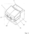
- the inventive multifunctional, mobile applicator 6 is equipped with an applicator 7, which, like FIG. 2 shows, on the high-flow therapy device 1 can be attached, and has an oxygen port 13 and a therapy air connection 14 for not shown in this figure supply hose 8.
- the applicator 7 consists of at least a top 15 and a bottom part 16th
- FIG. 3 shows the upper part 15 of the Applikatorsteckers 7 from below in partial view with a humidifier interface 17 through which the applicator plug 7 is supplied with conditioned therapeutic air from the high-flow therapy device 1.
- Shown is also a lower valve seat 23 with its seal 22 and above a valve body 24 which is rectilinearly movable in a guide 27. This is arranged in a pressure chamber 21.
- contacts 18/19 for the power supply and for signal and / or data lines are shown.
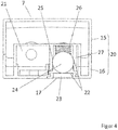
- FIG. 4 A vertical section through the applicator plug 7, FIG. 4 , Shows its housing 15 consisting of upper part 15 and bottom part 16 with the pressure chamber 21 into which therapeutic air can flow from below from the high-flow therapy device 1 via the humidifier interface 17.
- This humidifier interface 17 has at its upper end equipped with the seal 22 lower valve seat 23, on which the valve body 24 (eg, as here a ball or a cylindrical valve piston) rests when the applicator 7 is not seated on the high-flow therapy device 1.
- Above the valve body 24 is another, also provided with a seal 22 upper valve seat 25 which can connect to the oxygen port 13.
- a helical compression spring 26 is visible, which acts with its spring force on the valve body 24 and this presses on the seal 22 of the lower valve seat 23 of the humidifier 17.
- valve body 24 when the application plug 7 is firmly seated on the high flow therapy device 1 by means of latching or locking, by a fixedly attached thereto actuator 28, such as FIG. 5 shows, pushed up against the seal 22 of the upper valve seat 25.
- actuator 28 such as FIG. 5 shows
- FIG. 6 A vertical section through the applicator 7 of the multi-functional, mobile applicator applicator 6 in the plane of the therapeutic air connection 14 for the, not shown here, supply hose 8 shows FIG. 6 ,
- This therapy air connection 14 establishes the connection of the pressure chamber 21 with the supply hose 8.
- This connection is always open with attached, firmly locked or locked applicator plug 7 on the high-flow therapy device 1, since the actuation element 28 engages the valve body 24 from the in FIG. 5 shown seal 22 of the valve seat 23 lifts and the pressure chamber 21 is then always supplied with therapeutic air.
- the portable oxygen cylinder monitored for its degree of filling, should be connected to the oxygen connector 13 at the latest, if not already done. If the applicator 7 now removed from the high flow therapy device 1, the actuator 28 no longer acts on the valve body 24. By the force of the helical compression spring 26, the valve body 24 is pressed onto the seal 22 of the lower valve seat 23 and closes it. Oxygen then flows via the oxygen port 13 into the pressure chamber 21, in order to continue through the therapy air connection 14 into the supply hose 8.
- the multifunctional, mobile deployable applicator 6 with a small, easy-to-use oxygen or therapeutic air source without effort and comfortable to handle in his movement and allows only the mobile movement while maintaining this oxygen or. Therapy air supply without the high flow therapy device 1. The uninterrupted supply of oxygen or therapeutic air is thus reliably ensured during the movement, which is not possible without the valve assembly according to the invention described above and its function.
- FIG. 7 The view of the Applikatorsteckers 7 from below (Avemsteckseite to High Flow device) in FIG. 7 shows next to the humidifier interface 17, since the valve body 24 is not shown here, the helical compression spring 26 and the contacts 18 and 19 for the power supply and / or the signal and / or data lines (eg for data line 32, FIG. 8 ). These contacts correspond to corresponding contacts of the high flow therapy device 1.
- the multi-functional, mobile applicator 6 also allows monitoring functions (such as, for example, the time of use, temperature, service intervals, etc.), as described with respect to FIGS. 8 and 9 be described in more detail.
- monitoring functions such as, for example, the time of use, temperature, service intervals, etc.
- the Y-piece 9, which passes the therapy air can be equipped with a functional unit 29, such as FIG. 8 shows.
- This functional unit 29 contains sensors 33 (FIG. FIG. 9 ), which measure eg volume flow, humidity, temperature etc. The measured data are given by means of a data line 32 in the supply hose 8 to the applicator 7 and further via the contacts 19 to the high-flow therapy device 1.
- the functional unit 29 has transmitters and receivers for data transmission or transmits these data directly via the heating cable. These transmitters and receivers communicate with the corresponding receiver and transmitter either in the applicator plug 7 or in the high-flow therapy device 1.
- the data is forwarded to the high-flow therapy device 1 by means of the contacts 19, so that this parameter the therapeutic air can optimize.
- the power supply of the transmitter and receiver in the functional unit 29 can be done by batteries or rechargeable batteries.
- the power supply is also possible by means of the heating wires 31 running in the supply hose 8, which transmit the necessary energy. Also, the batteries can be charged by means of the heating wires 31 (see enlarged detail in FIG. 8 ).
- the functional unit 29 has, as FIG. 9 shows, via sensors 33 for measuring the parameters of the passing therapeutic air and an electronic processing unit 34, which transmits the measured data.
- a directional control valve 30 can be provided in the functional unit 29, which directs the therapeutic air differently to the forked hoses 10. In this way, the constant volumetric flow is ensured via the fork tubes 10 alternatively as a function of suitable sensors in the region of the prongs 12 at their outlet openings. The different resistance of the patient's airways through the nostrils is thus taken into account.
- the applicator plug 7 may further comprise a programmable microprocessor in which service data, the data and parameters of the patient using the multifunctional mobile deployable applicator 6 are stored. This data may be necessary for the individual control of the High Flow Therapy Device 1, as this allows the correct conditioning of the therapy air to be set. If the patient with his multifunctional, mobile deployable applicator 6 changes the previously used high-flow therapy device 1, then it automatically reverses and the patient immediately receives a conditioned therapeutic air with the parameters required and defined for him, ie he is in this respect selected high flow therapy device 1 independently. This requires that the high-flow therapy device 1 in turn has a corresponding control which can process the data from the microprocessor in the application plug 7.
- the data of the patient include, for example, the applicator-specific properties, such as flow limitation in a child applicator, identification of the applicator type, operating hours and Terms etc.
- a controlled directional valve can be located in the nosepiece 11 between the prongs 12 in order to keep the volume flow at the respective outlet openings of the prongs 12 constant.
- This control is carried out with the same technical solution as in the functional unit 29.
- the outlet cross sections of the tines 12 may be formed asymmetrically. Thus, in each case different cross-sectional areas and / or cross-sectional shapes of the outlet openings of the prongs 12 in the nostril are conceivable.
- the inner diameter of the oxygen port 13 is at least 1 mm. Preferably, the inner diameter of the oxygen port 13 is between 1 and 10 mm
- the inner diameter of the therapeutic air connection 14 is at least 2 mm. Preferably, the inner diameter of the therapeutic air connection 14 is between 2 and 25 mm.
- the aim of all measures described above is to provide a constant volume flow at the respective outlet openings of the tines 12, taking into account all parameters necessary for this purpose.
Landscapes
- Health & Medical Sciences (AREA)
- Pulmonology (AREA)
- Hematology (AREA)
- General Health & Medical Sciences (AREA)
- Engineering & Computer Science (AREA)
- Anesthesiology (AREA)
- Biomedical Technology (AREA)
- Heart & Thoracic Surgery (AREA)
- Veterinary Medicine (AREA)
- Life Sciences & Earth Sciences (AREA)
- Animal Behavior & Ethology (AREA)
- Emergency Medicine (AREA)
- Public Health (AREA)
- Otolaryngology (AREA)
- Infusion, Injection, And Reservoir Apparatuses (AREA)
- Respiratory Apparatuses And Protective Means (AREA)
- Surgical Instruments (AREA)
- Massaging Devices (AREA)
- Nozzles (AREA)
Description
- Nasale Insufflationssysteme für die High Flow Therapie sind bekannt, beispielsweise aus der
WO 2008/060 295 A2 . Gefilterte Luft wird von einem Gebläse angesaugt, verdichtet, mit Sauerstoff angereichert, dieses Gemisch in einem beheizten Befeuchter vernebelt und dem Patienten mittels Applikator als Therapieluft in die Nasenlöcher zugeführt, sofern es sich bei dem Patienten um einen Erwachsenen handelt. Bei Kindern wird zusätzlich ein Mundstück benötigt. - Bei dem aus oben genannter Offenlegungsschrift bekannten nasalen Insufflationssystem wird die Anreicherung der Therapieluft mit Sauerstoff in einem High Flow Therapiegerät mittels eines mikroprozessorgesteuerten Ventils erreicht. Die durch einen Lufteinlass im High Flow Therapiegerät angesaugte und gefilterte Umgebungsluft wird dadurch mit reinem Sauerstoff, der über einen gesonderten Anschluss am High Flow Therapiegerät zugeführt wird, gezielt vermischt. Neben dem Sauerstoffgehalt steuert der Mikroprozessor noch weitere Parameter der zugeführten Therapieluft, wie Gasdruck, Gasfluss, Kohlendioxidgehalt, Temperatur und Feuchte. Der Applikator ist bei Verwendung des nasalen Insufflationssystems unmittelbar und dauerhaft mit dem High Flow Therapiegerät verbunden.
- Aus der
DE 10 2005 000 922 A1 ist ein Applikator bekannt, der einen Applikatorstecker, einen Zuleitungsschlauch, ein Y-Stück, Gabelschläuche und ein Nasenstück mit Zinken aufweist. Der Applikatorstecker seinerseits weist elektrische und pneumatische Steckerteile auf. Von einem derartigen Applikator wird bei der vorliegenden Erfindung ausgegangen. - In der
DE 102 05 955 A1 ist ein Verfahren und eine Vorrichtung zur Bereitstellung von Atemgas offenbart, wobei ein Sauerstoffgenerator eine elektrolytische Zersetzung von Wasser in Wasserstoff und Sauerstoff durchführt und der erzeugte Sauerstoff komprimiert in eine Druckgasflasche eingespeist wird. Der Sauerstoffgenerator führt sowohl eine Befüllung der Druckgasflasche als auch eine Atemgasversorgung für eine Sauerstoffbrille mittels einer mit einem Verteiler versehenen Steuereinrichtung durch, der in Abhängigkeit von jeweiligen Steuerungsvorgaben eine Weiterleitung des Atemgases in Richtung auf die Sauerstoffbrille und/oder in Richtung der Druckgasflasche vorgibt. Ebenfalls offenbart ist, dass ein Patient wahlweise eine Verbindung über eine Verbrauchssteuerung als Anschlusselement an einen Sauerstoffgenerator oder an eine Druckgasflasche vornehmen kann. Damit einem Patienten ein relativ großer Bewegungsbereich in dessen Wohnung oder in einem anderen Aufenthaltsraum bereitgestellt wird, wird ein längerer Verbindungsschlauch zur Sauerstoffbrille vorgeschlagen. - Aus der
DE 38 349 A ist eine Atmungsvorrichtung zum Eindringen in Räume mit nicht atembarer Atmosphäre bekannt, wobei über einen durch einen Handhebel verstellbaren Dreiwegehahn die Luftzufuhr aus einem festangeschlossenen, mitführbaren Sauerstoffbehälter zum Atmungsorgan zu- oder abgestellt werden kann und gleichzeitig ein Schlauch, über den ansonsten eine Außenluftversorgung erfolgt, abrespektive angekuppelt wird, was durch ein am Kücken des Dreiwegehahns befestigtes Kupplungsteil erfolgt. - Ein insbesondere für Krankenhäuser vorgesehenes Beatmungssystem zur Durchführung von CPAP- oder Sauerstofftherapien ist aus der
US 6,158,430 A bekannt. Dieses besteht aus einem oder mehreren tragbaren Beatmungseinrichtungen, die mittels zugehöriger Schnittstellen an an unterschiedlichen Orten oder Stationen aufgestellten Dockingstationen betreibbar sind. Die Dockingstationen sind ihrerseits mit einer zentralen Gasversorgung des Krankenhauses verbunden, um die Sauerstoffzufuhr für die Beatmungseinrichtungen bereitzustellen. Ergänzend können auch einzelne Gasflaschen mit einer Dockingstation direkt verbunden werden. - Aus der
WO 2013/089714 A1 ist eine hybride Selbstrettungsausrüstung bekannt, welche es Personen ermöglicht, sich in widrigen Umgebungen, beispielsweise Bergwerken, Tunneln oder Tanks mit kontaminierter Luft, zu bewegen. Dazu sind alle notwendigen Bauteile wie Atemschlauch, Mundstück, Atemmaske, Nasenklammern, Schutzbrille etc. in einem tragbaren Gehäuse untergebracht. Weiterhin weist die Selbstrettungsausrüstung ein Ventilgehäuse mit mehreren Anschlüssen auf, an die wahlweise Atemluftschläuche oder Staubfilter angeschlossen werden können. - Da Applikatoren, wie sie z.B. aus der
DE 10 2005 000 922 A1 bekannt sind, immer zur Versorgung der Patienten mit dem High Flow Therapiegerät verbunden sein müssen und das High Flow Therapiegerät aufgrund seiner körperlichen Größe und Masse nicht beliebig transportierbar ist, ist der Patient an das High Flow Therapiegerät gebunden und somit immobil. Auch kann der Zuleitungsschlauch nicht beliebig lang ausgeführt werden, um dem Patienten etwas Bewegungsmöglichkeit einzuräumen, da die Parameter der zugeführten Therapieluft, besonders die Fluss- und Druckeigenschaften, nicht an dem Nasenstück mit den eingestellten Parametern sichergestellt werden können, wie sie das High Flow Therapiegerät erzeugt, da sich diese Parameter auf dem Weg vom High Flow Therapiegerät zum Nasenstück aufgrund von äußeren Einflüssen verändern. - Die nicht vorhandene Mobilität des Patienten ist von erheblichem Nachteil. Der Patient ist nicht in der Lage, kurzzeitig kleinere Wege ohne Gasversorgung und damit Atemunterstützung durchzuführen.
- Diesen Mangel zu beseitigen, gleichzeitig ein Maximum an Mobilität und Flexibilität zu erzielen und weiterhin eine Versorgung mit Sauerstoff oder Therapieluft zu ermöglichen, liegt der vorliegenden Erfindung als Aufgabe zugrunde. Diese Aufgabe wird durch einen multifunktionalen, mobil einsatzfähigen Applikator nach dem vorliegenden Patentanspruch 1 gelöst. Weitere Vorteile der Erfindung geben die Merkmale der Unteransprüche an.
- Der multifunktionale, mobil einsatzfähige Applikator ermöglicht mit seiner vorteilhaften Konstruktion des Applikatorsteckers einerseits die kontinuierliche Versorgung mit der vom High Flow Therapiegerät bereitgestellten konditionierten Therapieluft (TNI) und gewährleistet andererseits die Versorgung mit Sauerstoff (LTOT) oder mit Therapieluft, wenn der Patient den Applikatorstecker vom High Flow Therapiegerät abnimmt, beispielsweise um die Toilette, Küche etc. aufzusuchen, bei automatischer Umschaltung.
- Bei diesen Gängen wird der Patient von einer leicht zu handhabenden tragbaren Sauerstoff- oder Therapieluftquelle versorgt und somit ist die Sauerstoff- bzw. Therapieluft-Unterstützung ununterbrochen sichergestellt. Dies ist für den Patienten ein erheblicher Gewinn an Lebensqualität, er braucht ein Abnehmen oder Versagen seiner Atmungsunterstützung nicht zu befürchten und ist von daher vor einem möglichen lebensbedrohlichen Zustand geschützt.
- Darüber hinaus soll der Patient bei aufgestecktem Applikator in jedem seiner Nasenlöcher mit einem konstanten Volumenfluss der Therapieluft versorgt werden, da nur so der Totraum zuverlässig ausgespült wird. Dazu werden die Parameter der Therapieluft nahe beim Patienten gemessen und diese vorrangig im High Flow Therapiegerät so geregelt, dass der Volumenfluss konstant an den Austrittsöffnungen der Zinken der Nasenbrille gehalten wird. Dies wird durch vorteilhafte, in der Beschreibung näher erläuterte Maßnahmen erreicht.
- Die Ausgestaltung des Ventilkörpers als Kugel nach Patentanspruch 2 ermöglicht einen einfachen Aufbau mit den Ventilsitzen und ihren Dichtungen, um die Ventilfunktion sicherzustellen.
- Wird dagegen der Ventilkörper als Zylinderkolben ausgestaltet, wie im Patentanspruch 3 beansprucht, werden die bei dieser Ausführungsform üblichen Vorteile, wie z. B. bessere und leichtere Abdichtungen, erzielt.
- Da die im Applikator befindlichen elektronischen Bauteile mit Energie versorgt werden müssen, sind nach Patentanspruch 4 Kontakte für eine Stromversorgung und/oder für Signal- und Datenleitungen bereits im Applikatorstecker vorhanden, und es werden keine zusätzlichen externen Verbindungsleitungen benötigt.
- Nach Patentanspruch 5 ist im Y-Stück in vorteilhafter Weise eine Funktionseinheit eingebaut, die ein Wegeventil (Patentanspruch 6), Sender und Empfänger (Patentanspruch 7)und eine elektronische Verarbeitungseinheit (Patentanspruch 8) aufweist. Diese Bauteile werden in einfacher Weise über Heizdrähte im Zuleitungsschlauch oder Batterien oder Akkus mit Energie versorgt, wie die alternativ genannten Merkmale im Patentanspruch 9 aufzeigen.
- Der Applikatorstecker selbst kann nach Patentanspruch 10 mit einem programmierbaren Mikroprozessor ausgestattet sein, dessen Speicher nach Patentanspruch 11 Patientendaten sowie Parameterangaben der jeweils individuell benötigten Therapieluft und Servicedaten enthält, die für die Auswertung durch die Steuerfunktion im High Flow Therapiegerät benötigt werden. Bei einem Auswechseln der Therapiegeräte kann somit der Patient ohne Neueinstellungen am Gerät mit gleichbleibender, ihm zugehöriger Therapieluft versorgt werden, da die Einstellwerte vom Applikatorstecker übernommen werden können.
- Um individueller auf anatomische Asymmetrien reagieren zu können, ist das Y-Stück nicht näher als 5 mm von den Zinken angeordnet, wie Patentanspruch 12 festlegt.
- Die in Patentanspruch 13 beanspruchte Verwendung von antibakteriell beschichteten Werkstoffen schützt den Patienten vor Infektionen.
- Weiterhin ist von Vorteil, wie aus Patentanspruch 14 ersichtlich, dass am Sauerstoffanschluss statt Sauerstoff auch Therapieluft zugeführt werden kann.
- Es zeigen:
- Figur 1
- ein nasales Insufflationssystem nach dem Stand der Technik,
- Figur 2
- einen mit einem High Flow Therapiegerät verbundenen Applikatorstecker nach der Erfindung,
- Figur 3
- ein Oberteil des erfindungsgemäßen Applikatorsteckers,
- Figur 4
- einen vertikalen Schnitt durch den erfindungsgemäßen Applikatorstecker,
- Figur 5
- einen vertikalen Schnitt durch den erfindungsgemäßen Applikatorstecker mit Betätigungselement in der Ebene des Sauerstoffanschlusses,
- Figur 6
- einen vertikalen Schnitt durch das Oberteil des erfindungsgemäßen Applikatorsteckers in der Ebene des Therapieluftanschlusses,
- Figur 7
- eine Bodenansicht des Applikatorsteckers nach der Erfindung,
- Figur 8
- einen erfindungsgemäßen Applikator mit Funktionseinheit,
- Figur 9
- Details der Funktionseinheit.
-
Figur 1 zeigt ein nasales Insufflationssystem bestehend aus einem High Flow Therapiegerät 1 und einem Applikator 6 nach dem Stand der Technik. Am High Flow Therapiegerät 1 sind der Einlass für die Umgebungsluft 2, der Anschluss für die Sauerstoffzufuhr 3, die Bedien- und Anzeigeeinrichtung 4 und am Ausgang für die Therapieluft der Anschluss 5 für den Applikator 6 erkennbar. Der Applikator 6 besteht grundsätzlich zumindest aus einem Applikatorstecker 7, einem Zuleitungsschlauch 8, einem Y-Stück 9, Gabelschläuchen 10 und einem Nasenstück 11 mit Zinken 12. - Der erfindungsgemäße multifunktionale, mobil einsatzfähige Applikator 6 ist mit einem Applikatorstecker 7 ausgestattet, der, wie
Figur 2 zeigt, auf dem High Flow Therapiegerät 1 anbringbar ist, und besitzt einen Sauerstoffanschluss 13 und einen Therapieluftanschluss 14 für den in dieser Figur nicht gezeigten Zuleitungsschlauch 8. Der Applikatorstecker 7 besteht mindestens aus einem Oberteil 15 und einem Bodenteil 16. -
Figur 3 zeigt das Oberteil 15 des Applikatorsteckers 7 von unten in teilweiser Ansicht mit einer Befeuchterschnittstelle 17, durch welche der Applikatorstecker 7 mit konditionierter Therapieluft vom High Flow Therapiegerät 1 versorgt wird. Dargestellt ist weiterhin ein unterer Ventilsitz 23 mit seiner Dichtung 22 und darüber ein Ventilkörper 24, welcher in einer Führung 27 geradlinig bewegbar ist. Diese ist in einer Druckkammer 21 angeordnet. Daneben sind Kontakte 18/19 für die Stromversorgung und für Signal- und/oder Datenleitungen dargestellt. - Ein vertikaler Schnitt durch den Applikatorstecker 7,
Figur 4 , zeigt sein aus Oberteil 15 und Bodenteil 16 bestehendes Gehäuse 20 mit der Druckkammer 21, in die von unten aus dem High Flow Therapiegerät 1 über die Befeuchterschnittstelle 17 Therapieluft einströmen kann. Diese Befeuchterschnittstelle 17 besitzt an ihrem oberen Ende den mit der Dichtung 22 ausgestatteten unteren Ventilsitz 23, auf welchem der Ventilkörper 24 (z.B. wie hier eine Kugel oder ein zylindrischer Ventilkolben) ruht, wenn der Applikatorstecker 7 nicht auf dem High Flow Therapiegerät 1 sitzt. Oberhalb des Ventilkörpers 24 befindet sich ein weiterer, ebenfalls mit einer Dichtung 22 ausgestatteter oberer Ventilsitz 25, der eine Verbindung mit dem Sauerstoffanschluss 13 herstellen kann. Auch ist eine Schraubendruckfeder 26 sichtbar, welche mit ihrer Federkraft auf den Ventilkörper 24 einwirkt und diesen so auf die Dichtung 22 des unteren Ventilsitzes 23 der Befeuchterschnittstelle 17 drückt. So wird, wenn der Applikatorstecker 7 vom High Flow Therapiegerät 1 abgenommen ist, die Befeuchterschnittstelle 17 zuverlässig abgedichtet. - Der Ventilkörper 24 wird, wenn der Applikationsstecker 7 auf dem High Flow Therapiegerät 1 mittels Verrastung oder Arretierung fest sitzt, durch ein an diesem ortsfest angebrachtes Betätigungselement 28, wie
Figur 5 zeigt, nach oben gegen die Dichtung 22 des oberen Ventilsitzes 25 gedrückt. Somit kann kein Sauerstoff über den Sauerstoffanschluss 13 in die Druckkammer 21 einströmen. Dies stellt sicher, dass die vom High Flow Therapiegerät 1 bereitgestellte Therapieluft in die Druckkammer 21 hinein und weiter über den, hier nicht in dieser Schnittebene darstellbaren, Therapieluftanschluss 14 zum Zuleitungsschlauch 8 strömt. Dieser Strömungsweg ist der Regelfall. - Einen vertikalen Schnitt durch den Applikatorstecker 7 des multifunktionalen, mobil einsatzfähigen Applikators 6 in der Ebene des Therapieluftanschlusses 14 für den, hier nicht dargestellten, Zuleitungsschlauch 8 zeigt
Figur 6 . Dieser Therapieluftanschluss 14 stellt die Verbindung der Druckkammer 21 mit dem Zuleitungsschlauch 8 her. Diese Verbindung ist bei aufgesetztem, fest verrastetem oder arretiertem Applikatorstecker 7 auf dem High Flow Therapiegerät 1 immer offen, da das Betätigungselement 28 den Ventilköper 24 von der inFigur 5 gezeigten Dichtung 22 des Ventilsitzes 23 abhebt und die Druckkammer 21 dann immer mit Therapieluft versorgt. - Besteht der Wunsch des Patienten, für einen abschätzbaren Zeitraum mobil zu sein, ist die tragbare und auf ihren Füllungsgrad überwachte Sauerstoffflasche spätestens dann an den Sauerstoffanschluss 13 anzuschließen, falls dies nicht schon erfolgte. Wird der Applikatorstecker 7 nun von dem High Flow Therapiegerät 1 abgenommen, wirkt das Betätigungselement 28 nicht mehr auf den Ventilkörper 24. Durch die Kraft der Schraubendruckfeder 26 wird der Ventilkörper 24 auf die Dichtung 22 des unteren Ventilsitzes 23 gepresst und verschließt diesen. Sauerstoff strömt dann über den Sauerstoffanschluss 13 in die Druckkammer 21 ein, um weiter über den Therapieluftanschluss 14 in den Zuleitungsschlauch 8 zu gelangen. Für den Patienten ist der multifunktionale, mobil einsatzfähige Applikator 6 mit einer kleinen, leicht zu handhabenden Sauerstoff- oder Therapieluftquelle ohne Aufwand und bequem bei seiner Bewegung zu handhaben und ermöglicht erst dadurch die mobile Bewegungsmöglichkeit unter Beibehaltung dieser Sauerstoff-bzw. Therapieluft-Versorgung ohne das High Flow Therapiegerät 1. Die ununterbrochene Versorgung mit Sauerstoff- bzw. Therapieluft wird so auch während der Bewegung zuverlässig sichergestellt, was ohne den vorstehend beschriebenen, erfindungsgemäßen Ventilaufbau und seine Funktion nicht möglich ist.
- Die Ansicht des Applikatorsteckers 7 von unten (Aufsteckseite zum High Flow Gerät) in
Figur 7 zeigt neben der Befeuchterschnittstelle 17, da der Ventilkörper 24 hier nicht dargestellt ist, die Schraubendruckfeder 26 sowie die Kontakte 18 und 19 für die Stromversorgung und/oder die Signal- und/oder Datenleitungen (z.B. für Datenleitung 32,Figur 8 ). Diese Kontakte korrespondieren mit entsprechenden Kontakten des High Flow Therapiegeräts 1. - Neben der Funktion der mobilen Einsatzfähigkeit ermöglicht der erfindungsgemäße multifunktionale, mobil einsatzfähige Applikator 6 noch Überwachungsfunktionen (wie z. B. Nutzungszeit, Temperatur, Serviceintervalle usw.), wie sie im Hinblick auf die
Figuren 8 und9 näher beschrieben werden. - Bei Bedarf kann das Y-Stück 9, welches die Therapieluft durchleitet, mit einer Funktionseinheit 29 ausgestattet werden, wie
Figur 8 zeigt. Diese Funktionseinheit 29 enthält Sensoren 33 (Figur 9 ), welche z.B. Volumenfluss, Feuchte, Temperatur etc. messen. Die gemessenen Daten werden mittels einer Datenleitung 32 im Zuleitungsschlauch 8 zum Applikatorstecker 7 und weiter über die Kontakte 19 zum High Flow Therapiegerät 1 gegeben. Alternativ zur Datenleitung 32 verfügt die Funktionseinheit 29 über Sender und Empfänger zur Datenübertragung oder überträgt diese Daten direkt über die Heizleitung. Diese Sender und Empfänger kommunizieren mit dem entsprechenden Empfänger und Sender entweder im Applikatorstecker 7 oder im High Flow Therapiegerät 1. Wenn Sender und Empfänger im Applikatorstecker 7 eingebaut sind, werden die Daten mittels der Kontakte 19 dem High Flow Therapiegerät 1 weitergeleitet, damit dieses die Parameter der Therapieluft optimieren kann. Die Energieversorgung der Sender und Empfänger in der Funktionseinheit 29 kann durch Batterien oder Akkus erfolgen. Möglich ist auch die Energieversorgung mittels der im Zuleitungsschlauch 8 verlaufenden Heizdrähte 31, welche die notwendige Energie mit übertragen. Auch können die Akkus mittels der Heizdrähte 31 geladen werden (siehe vergrößerten Ausschnitt inFigur 8 ). - Um diese Funktionen auszuführen, verfügt die Funktionseinheit 29, wie
Figur 9 zeigt, über Sensoren 33 zum Messen der Parameter der vorbei strömenden Therapieluft und eine elektronische Verarbeitungseinheit 34, welche die gemessenen Daten weitergibt. - Neben den genannten Sensoren 33 kann in der Funktionseinheit 29 ein Wegeventil 30 vorgesehen sein, welches die Therapieluft unterschiedlich zu den Gabelschläuchen 10 leitet. Damit wird über die Gabelschläuche 10 alternativ in Abhängigkeit von geeigneten Sensoren im Bereich der Zinken 12 an deren Austrittsöffnungen der konstante Volumenfluss sicher gestellt. Der unterschiedliche Widerstand der Atemwege des Patienten durch die Nasenlöcher wird so berücksichtigt.
- Der Applikatorstecker 7 kann weiterhin einen programmierbaren Mikroprozessor aufweisen, in welchem Servicedaten, die Daten und Parameter des Patienten, der den multifunktionalen, mobil einsatzfähigen Applikator 6 benutzt, abgelegt sind. Diese Daten können für die individuelle Steuerung des High Flow Therapiegeräts 1 notwendig sein, da so die korrekte Konditionierung der Therapieluft eingestellt werden kann. Wechselt der Patient mit seinem multifunktionalen, mobil einsatzfähigen Applikator 6 das bisher benutzte High Flow Therapiegerät 1, so stellt sich dieses automatisch um und der Patient erhält sofort eine konditionierte Therapieluft mit den für ihn notwendigen und definierten Parametern, er ist also in dieser Beziehung von dem gewählten High Flow Therapiegerät 1 unabhängig. Dies setzt voraus, dass das High Flow Therapiegerät 1 seinerseits über eine entsprechende Steuerung verfügt, welche die Daten aus dem Mikroprozessor im Applikationsstecker 7 verarbeiten kann.
- Zu den Daten des Patienten zählen beispielsweise auch die applikatorspezifischen Eigenschaften, wie Flussbegrenzung bei einem Kinder-applikator, Identifikation des Applikatortyps, Betriebsstunden und Laufzeiten etc..
- Alternativ zu dem Wegeventil 30 in der Funktionseinheit 29 kann sich im Nasenstück 11 zwischen den Zinken 12 ein angesteuertes Wegeventil befinden, um den Volumenfluss an den jeweiligen Austrittsöffnungen der Zinken 12 konstant zu halten. Diese Ansteuerung erfolgt mit der gleichen technischen Lösung, wie in der Funktionseinheit 29. Auch können die Austrittsquerschnitte der Zinken 12 asymmetrisch ausgebildet sein. So sind des Weiteren jeweils unterschiedliche Querschnittsflächen und/oder Querschnittsformen der Austrittsöffnungen der Zinken 12 im Nasenloch denkbar.
- Der Innendurchmesser des Sauerstoffanschlusses 13 beträgt dabei mindestens 1 mm. Vorzugsweise liegt der Innendurchmesser des Sauerstoffanschlusses 13 zwischen 1 und 10 mm
- Der Innendurchmesser des Therapieluftanschlusses 14 beträgt mindestens 2 mm. Vorzugsweise liegt der Innendurchmesser des Therapieluftanschlusses 14 zwischen 2 und 25 mm.
- Ziel aller vorstehend beschriebenen Maßnahmen ist es, an den jeweiligen Austrittsöffnungen der Zinken 12 einen konstanten Volumenfluss unter Berücksichtigung aller dafür notwendigen Parameter bereitzustellen.
-
- 1
- High Flow Therapiegerät
- 2
- Einlass für Umgebungsluft
- 3
- Anschluss für Sauerstoffzufuhr
- 4
- Bedien- und Anzeigeteil des High Flow Therapiegeräts
- 5
- Anschluss für Applikatorstecker
- 6
- Applikator
- 7
- Applikatorstecker
- 8
- Zuleitungsschlauch
- 9
- Y-Stück
- 10
- Gabelschläuche
- 11
- Nasenstück
- 12
- Zinken
- 13
- Sauerstoffanschluss
- 14
- Therapieluftanschluss
- 15
- Oberteil des Applikatorsteckers
- 16
- Bodenteil des Applikatorsteckers
- 17
- Befeuchterschnittstelle
- 18
- Kontakte für Stromversorgung
- 19
- Kontakte für Signal- und/oder Datenleitungen
- 20
- Gehäuse des Applikatorsteckers
- 21
- Druckkammer
- 22
- Dichtung
- 23
- unterer Ventilsitz
- 24
- Ventilkörper
- 25
- oberer Ventilsitz
- 26
- Schraubendruckfeder
- 27
- Führung für Ventilkörper
- 28
- Betätigungselement
- 29
- Funktionseinheit
- 30
- Wegeventil
- 31
- Heizdrähte
- 32
- Datenleitung
- 33
- Sensoren
- 34
- elektronische Verarbeitungseinheit
Claims (14)
- Multifunktionaler, mobil einsatzfähiger Applikator 6 aufweisend einen Applikatorstecker 7, einen Zuleitungsschlauch 8, ein Y-Stück 9, Gabelschläuche 10 und ein Nasenstück 11 mit Zinken 12,
dadurch gekennzeichnet,
dass der Applikatorstecker 7 eine Druckkammer 21 enthält, die eine Befeuchterschnittstelle 17 zur Verbindung mit einem High Flow Therapiegerät 1, einen Sauerstoffanschluss 13 mit einem Öffnungsdurchmesser von mindestens 1 mm und einen Therapieluftanschluss 14 für den Zuleitungsschlauch 8 aufweist, wobei die Befeuchterschnittstelle 17 und der Sauerstoffanschluss 13 innerhalb der Druckkammer 21 jeweils einen mit einer Dichtung 22 versehenen unteren und oberen Ventilsitz 23, 25 aufweisen und zwischen diesen Ventilsitzen 23, 25 ein Ventilkörper 24 bewegbar ist und dieser Ventilkörper 24 aus Richtung des Sauerstoffanschlusses 13 von einer Schraubendruckfeder 26 kraftbeaufschlagt wird, andererseits von einem Betätigungselement 28 des High Flow Therapiegeräts 1 gegen den oberen Ventilsitz 25 gedrückt wird, wenn der Applikatorstecker 7 auf dem High Flow Therapiegerät 1 arretiert sitzt. - Multifunktionaler, mobil einsatzfähiger Applikator 6 nach Patentanspruch 1,
dadurch gekennzeichnet,
dass der Ventilkörper 24 eine Kugel ist. - Multifunktionaler, mobil einsatzfähiger Applikator 6 nach Patentanspruch 1,
dadurch gekennzeichnet,
dass der Ventilkörper 24 ein Zylinderkolben ist. - Multifunktionaler, mobil einsatzfähiger Applikator 6 nach Patentanspruch 1, 2 oder 3,
dadurch gekennzeichnet,
dass der Applikatortecker 7 Kontakte 18, 19 für eine Stromversorgung und/oder für Signal- und/oder Datenleitungen aufweist. - Multifunktionaler, mobil einsatzfähiger Applikator 6 nach einem der vorhergehenden Patentansprüche,
dadurch gekennzeichnet,
dass im Y-Stück 9 eine Funktionseinheit 29 integriert ist, welche Sensoren 33 enthält. - Multifunktionaler, mobil einsatzfähiger Applikator 6 nach einem der vorhergehenden Patentansprüche,
dadurch gekennzeichnet,
dass im Y-Stück 9 eine Funktionseinheit 29 integriert ist, welche ein Wegeventil 30 aufweist. - Multifunktionaler, mobil einsatzfähiger Applikator 6 nach einem der vorhergehenden Patentansprüche,
dadurch gekennzeichnet,
dass im Y-Stück 9 eine Funktionseinheit 29 integriert ist, welche Sender und Empfänger aufweist, die entweder mit Sendern und Empfängern im Applikatorstecker 7 oder im High Flow Therapiegerät 1 kommunizieren. - Multifunktionaler, mobil einsatzfähiger Applikator 6 nach einem der vorhergehenden Patentansprüche,
dadurch gekennzeichnet,
dass im Y-Stück 9 eine Funktionseinheit 29 integriert ist, welche eine elektronische Verarbeitungseinheit 34 aufweist. - Multifunktionaler, mobil einsatzfähiger Applikator 6 nach Patentanspruch 8,
dadurch gekennzeichnet,
dass die elektronische Verarbeitungseinheit 34 über Heizdrähte 31 im Zuleitungsschlauch 8 oder durch eine Batterie oder einen Akku mit Energie versorgt wird. - Multifunktionaler, mobil einsatzfähiger Applikator 6 nach einem der vorhergehenden Patentansprüche,
dadurch gekennzeichnet,
dass der Applikatorstecker 7 einen programmierbaren Mikroprozessor aufweist. - Multifunktionaler, mobil einsatzfähiger Applikator 6 nach Patentanspruch 10,
dadurch gekennzeichnet,
dass im Speicher des programmierbaren Mikroprozessors Servicedaten, Daten des Patienten und seiner individuell benötigten Therapieparameter abgelegt sind. - Multifunktionaler, mobil einsatzfähiger Applikator 6 nach einem der vorhergehenden Patentansprüche,
dadurch gekennzeichnet,
dass das Y-Stück 9 nicht näher als 5 mm von den Zinken 12 angeordnet ist. - Multifunktionaler, mobil einsatzfähiger Applikator 6 nach einem der vorhergehenden Patentansprüche,
dadurch gekennzeichnet,
dass die verwendeten Werkstoffe antibakteriell beschichtet sind. - Multifunktionaler, mobil einsatzfähiger Applikator 6 nach einem der vorhergehenden Patentansprüche,
dadurch gekennzeichnet,
dass im mobilen Einsatz eine kleine, leicht zu handhabende Sauerstoff- oder Therapieluftquelle mit dem Sauerstoffanschluss 13 verbunden ist.
Applications Claiming Priority (1)
| Application Number | Priority Date | Filing Date | Title |
|---|---|---|---|
| PCT/EP2014/074457 WO2016074722A1 (de) | 2014-11-13 | 2014-11-13 | Multifunktionaler, mobil einsatzfähiger applikator |
Publications (2)
| Publication Number | Publication Date |
|---|---|
| EP3218039A1 EP3218039A1 (de) | 2017-09-20 |
| EP3218039B1 true EP3218039B1 (de) | 2018-07-25 |
Family
ID=52011157
Family Applications (1)
| Application Number | Title | Priority Date | Filing Date |
|---|---|---|---|
| EP14808525.1A Active EP3218039B1 (de) | 2014-11-13 | 2014-11-13 | Multifunktionaler, mobil einsatzfähiger applikator |
Country Status (8)
| Country | Link |
|---|---|
| US (1) | US11224712B2 (de) |
| EP (1) | EP3218039B1 (de) |
| JP (1) | JP6386667B2 (de) |
| KR (1) | KR20170070067A (de) |
| AU (1) | AU2014411010B2 (de) |
| BR (1) | BR112017007913A2 (de) |
| TW (1) | TWI579009B (de) |
| WO (1) | WO2016074722A1 (de) |
Families Citing this family (3)
| Publication number | Priority date | Publication date | Assignee | Title |
|---|---|---|---|---|
| EP4035714B1 (de) | 2013-08-09 | 2025-09-24 | Fisher & Paykel Healthcare Limited | Asymmetrische nasale verabreichungselemente und kupplungen für nasale schnittstellen |
| US10007238B1 (en) | 2015-01-22 | 2018-06-26 | John C. Taube | Oxygen mixing and delivery |
| CN109157723B (zh) * | 2018-08-09 | 2019-04-26 | 南通市第一人民医院 | 一种无创呼吸机中的呼吸机与氧气连接管的连接装置 |
Family Cites Families (23)
| Publication number | Priority date | Publication date | Assignee | Title |
|---|---|---|---|---|
| DE238349C (de) | ||||
| GB1511233A (en) * | 1974-06-04 | 1978-05-17 | Pneupac Ltd | Gas valve mechanisms |
| US4919127A (en) * | 1988-05-03 | 1990-04-24 | Pell Donald M | Endotracheal tube connector |
| AUPN344195A0 (en) * | 1995-06-08 | 1995-07-06 | Rescare Limited | Monitoring of oro-nasal respiration |
| US6119291A (en) * | 1995-08-04 | 2000-09-19 | Hill-Rom, Inc. | Percussion and vibration therapy apparatus |
| SE9704663D0 (sv) * | 1997-12-15 | 1997-12-15 | Siemens Elema Ab | Ventilator system |
| US20050121033A1 (en) * | 1998-02-25 | 2005-06-09 | Ric Investments, Llc. | Respiratory monitoring during gas delivery |
| BR0008867A (pt) | 1999-03-12 | 2002-01-02 | Glaxo Group Ltd | Válvula dosadora para um recipiente de aerossol, recipiente de aerossol, dispositivo de inalação para distribuir medicamento para um paciente, e, uso do mesmo |
| MXPA02010884A (es) * | 2000-05-05 | 2003-03-27 | Aerogen Ireland Ltd | Aparato y metodo para el suministro de medicamentos al sistema respiratorio. |
| US6651658B1 (en) * | 2000-08-03 | 2003-11-25 | Sequal Technologies, Inc. | Portable oxygen concentration system and method of using the same |
| US6648862B2 (en) * | 2001-11-20 | 2003-11-18 | Spheric Products, Ltd. | Personally portable vacuum desiccator |
| DE10205955A1 (de) | 2002-02-12 | 2003-08-21 | Weinmann G Geraete Med | Verfahren und Vorrichtung zur Bereitstellung von Atemgas |
| AU2004263115B2 (en) * | 2003-08-04 | 2010-06-10 | Carefusion 203, Inc. | Portable ventilator system |
| US7273051B2 (en) | 2004-01-22 | 2007-09-25 | Air Products And Chemicals, Inc. | Dual mode medical oxygen concentrator |
| US7617826B1 (en) * | 2004-02-26 | 2009-11-17 | Ameriflo, Inc. | Conserver |
| DE102005000922A1 (de) * | 2005-01-07 | 2006-07-20 | Seleon Gmbh | Luftbrille, Nasenstück, Y-Stück sowie Verfahren |
| DE102005038349B4 (de) | 2005-08-11 | 2008-04-10 | Fritz Stephan Gmbh | Pneumatischer Nebenwiderstand sowie Gasmischer |
| US7762253B2 (en) * | 2005-12-12 | 2010-07-27 | General Electric Company | Multiple lumen monitored drug delivery nasal cannula system |
| AU2006348403A1 (en) | 2005-12-14 | 2008-05-22 | Mergenet Medical Inc. | High flow therapy device |
| CA2700878C (en) * | 2007-09-26 | 2018-07-24 | Breathe Technologies, Inc. | Methods and devices for providing inspiratory and expiratory flow relief during ventilation therapy |
| CN201658727U (zh) | 2010-04-29 | 2010-12-01 | 张燕 | 氧气吸入治疗器械 |
| WO2013089714A1 (en) | 2011-12-14 | 2013-06-20 | Draeger Safety, Inc. | Hybrid self-rescue equipment |
| TWM485052U (zh) * | 2014-05-29 | 2014-09-01 | Besmed Health Business Corp | 氣體潮濕瓶 |
-
2014
- 2014-11-13 BR BR112017007913A patent/BR112017007913A2/pt not_active IP Right Cessation
- 2014-11-13 KR KR1020177010803A patent/KR20170070067A/ko not_active Ceased
- 2014-11-13 EP EP14808525.1A patent/EP3218039B1/de active Active
- 2014-11-13 US US15/524,340 patent/US11224712B2/en active Active
- 2014-11-13 AU AU2014411010A patent/AU2014411010B2/en not_active Expired - Fee Related
- 2014-11-13 JP JP2017522403A patent/JP6386667B2/ja active Active
- 2014-11-13 WO PCT/EP2014/074457 patent/WO2016074722A1/de not_active Ceased
-
2015
- 2015-09-30 TW TW104132026A patent/TWI579009B/zh not_active IP Right Cessation
Non-Patent Citations (1)
| Title |
|---|
| None * |
Also Published As
| Publication number | Publication date |
|---|---|
| US20170312471A1 (en) | 2017-11-02 |
| JP2017533749A (ja) | 2017-11-16 |
| AU2014411010B2 (en) | 2018-04-12 |
| JP6386667B2 (ja) | 2018-09-05 |
| BR112017007913A2 (pt) | 2018-01-23 |
| AU2014411010A1 (en) | 2017-04-20 |
| US11224712B2 (en) | 2022-01-18 |
| WO2016074722A1 (de) | 2016-05-19 |
| TW201618826A (zh) | 2016-06-01 |
| TWI579009B (zh) | 2017-04-21 |
| KR20170070067A (ko) | 2017-06-21 |
| EP3218039A1 (de) | 2017-09-20 |
Similar Documents
| Publication | Publication Date | Title |
|---|---|---|
| DE102007019487B3 (de) | Modulares Beatmungssystem für die maschinelle Beatmung eines Patienten | |
| EP1960025B1 (de) | Schlauchsystem für beatmungsgeräte | |
| DE3900183C2 (de) | ||
| EP1622665B1 (de) | Vorrichtung zur Beatmung mit einem doppellumigen Endotrachealtubus | |
| DE112012003304T5 (de) | Leitungsverbinder für eine Vorrichtung zur Beatmung von Patienten | |
| DE2254650A1 (de) | Atemgeraet mit turbine | |
| DE2312071A1 (de) | Apparat zur kuenstlichen beatmung | |
| DE60020383T2 (de) | Zuführventil und membran für eine pneumatisch arbeitende gasbedarfsvorrichtung | |
| DE102016013740A1 (de) | System zum Beatmen von Patienten | |
| DE202015105799U1 (de) | Atemmaske | |
| EP2371412B1 (de) | Beatmungs- oder Anästhesiesystem | |
| EP3854436A1 (de) | Ventil-anordnung mit absperreinheit für ein beatmungsgerät | |
| WO2016074722A1 (de) | Multifunktionaler, mobil einsatzfähiger applikator | |
| EP3957347B1 (de) | Beatmungsgerät für high-flow-sauerstofftherapie | |
| DE102013017348B3 (de) | Multifunktionaler, mobil einsatzfähiger Applikator | |
| DE102019121712A1 (de) | Bidirektional durchströmbare Atemgas-Ventilbaugruppe und Beatmungsvorrichtung mit einer solchen | |
| DE102012002632B4 (de) | Beatmungssystem und Konnektorsystem hierfür zur Verminderung von Kontaminationen | |
| DE102014000884A1 (de) | Verfahren und Vorrichtung zur Beatmung | |
| DE102017009605A1 (de) | System zum Beatmen eines Patienten | |
| DE102009015928B4 (de) | Vorrichtung zur Anreicherung von Atemgas mit Sauerstoff | |
| EP2724743A1 (de) | Winkelstück für eine Beatmungsmaske | |
| DE60108787T2 (de) | Anordnung zur künstlichen beatmung der lungen | |
| DE102011014018B4 (de) | Vorrichtung zum Filtern von Atemgas | |
| DE102005012753A1 (de) | Vorrichtung zur Beatmung | |
| DE102022100889A1 (de) | Atemstation für eine Dekompressionskammer und Dekompressionskammer |
Legal Events
| Date | Code | Title | Description |
|---|---|---|---|
| STAA | Information on the status of an ep patent application or granted ep patent |
Free format text: STATUS: THE INTERNATIONAL PUBLICATION HAS BEEN MADE |
|
| PUAI | Public reference made under article 153(3) epc to a published international application that has entered the european phase |
Free format text: ORIGINAL CODE: 0009012 |
|
| STAA | Information on the status of an ep patent application or granted ep patent |
Free format text: STATUS: REQUEST FOR EXAMINATION WAS MADE |
|
| 17P | Request for examination filed |
Effective date: 20170516 |
|
| AK | Designated contracting states |
Kind code of ref document: A1 Designated state(s): AL AT BE BG CH CY CZ DE DK EE ES FI FR GB GR HR HU IE IS IT LI LT LU LV MC MK MT NL NO PL PT RO RS SE SI SK SM TR |
|
| AX | Request for extension of the european patent |
Extension state: BA ME |
|
| GRAP | Despatch of communication of intention to grant a patent |
Free format text: ORIGINAL CODE: EPIDOSNIGR1 |
|
| STAA | Information on the status of an ep patent application or granted ep patent |
Free format text: STATUS: GRANT OF PATENT IS INTENDED |
|
| DAX | Request for extension of the european patent (deleted) | ||
| INTG | Intention to grant announced |
Effective date: 20180221 |
|
| GRAS | Grant fee paid |
Free format text: ORIGINAL CODE: EPIDOSNIGR3 |
|
| GRAA | (expected) grant |
Free format text: ORIGINAL CODE: 0009210 |
|
| STAA | Information on the status of an ep patent application or granted ep patent |
Free format text: STATUS: THE PATENT HAS BEEN GRANTED |
|
| REG | Reference to a national code |
Ref country code: HK Ref legal event code: DE Ref document number: 1242635 Country of ref document: HK |
|
| AK | Designated contracting states |
Kind code of ref document: B1 Designated state(s): AL AT BE BG CH CY CZ DE DK EE ES FI FR GB GR HR HU IE IS IT LI LT LU LV MC MK MT NL NO PL PT RO RS SE SI SK SM TR |
|
| REG | Reference to a national code |
Ref country code: GB Ref legal event code: FG4D Free format text: NOT ENGLISH |
|
| REG | Reference to a national code |
Ref country code: CH Ref legal event code: EP |
|
| REG | Reference to a national code |
Ref country code: AT Ref legal event code: REF Ref document number: 1021097 Country of ref document: AT Kind code of ref document: T Effective date: 20180815 |
|
| REG | Reference to a national code |
Ref country code: IE Ref legal event code: FG4D Free format text: LANGUAGE OF EP DOCUMENT: GERMAN |
|
| REG | Reference to a national code |
Ref country code: DE Ref legal event code: R096 Ref document number: 502014008989 Country of ref document: DE |
|
| REG | Reference to a national code |
Ref country code: NL Ref legal event code: MP Effective date: 20180725 |
|
| REG | Reference to a national code |
Ref country code: LT Ref legal event code: MG4D |
|
| PG25 | Lapsed in a contracting state [announced via postgrant information from national office to epo] |
Ref country code: NL Free format text: LAPSE BECAUSE OF FAILURE TO SUBMIT A TRANSLATION OF THE DESCRIPTION OR TO PAY THE FEE WITHIN THE PRESCRIBED TIME-LIMIT Effective date: 20180725 |
|
| PG25 | Lapsed in a contracting state [announced via postgrant information from national office to epo] |
Ref country code: NO Free format text: LAPSE BECAUSE OF FAILURE TO SUBMIT A TRANSLATION OF THE DESCRIPTION OR TO PAY THE FEE WITHIN THE PRESCRIBED TIME-LIMIT Effective date: 20181025 Ref country code: RS Free format text: LAPSE BECAUSE OF FAILURE TO SUBMIT A TRANSLATION OF THE DESCRIPTION OR TO PAY THE FEE WITHIN THE PRESCRIBED TIME-LIMIT Effective date: 20180725 Ref country code: IS Free format text: LAPSE BECAUSE OF FAILURE TO SUBMIT A TRANSLATION OF THE DESCRIPTION OR TO PAY THE FEE WITHIN THE PRESCRIBED TIME-LIMIT Effective date: 20181125 Ref country code: PL Free format text: LAPSE BECAUSE OF FAILURE TO SUBMIT A TRANSLATION OF THE DESCRIPTION OR TO PAY THE FEE WITHIN THE PRESCRIBED TIME-LIMIT Effective date: 20180725 Ref country code: SE Free format text: LAPSE BECAUSE OF FAILURE TO SUBMIT A TRANSLATION OF THE DESCRIPTION OR TO PAY THE FEE WITHIN THE PRESCRIBED TIME-LIMIT Effective date: 20180725 Ref country code: BG Free format text: LAPSE BECAUSE OF FAILURE TO SUBMIT A TRANSLATION OF THE DESCRIPTION OR TO PAY THE FEE WITHIN THE PRESCRIBED TIME-LIMIT Effective date: 20181025 Ref country code: GR Free format text: LAPSE BECAUSE OF FAILURE TO SUBMIT A TRANSLATION OF THE DESCRIPTION OR TO PAY THE FEE WITHIN THE PRESCRIBED TIME-LIMIT Effective date: 20181026 Ref country code: LT Free format text: LAPSE BECAUSE OF FAILURE TO SUBMIT A TRANSLATION OF THE DESCRIPTION OR TO PAY THE FEE WITHIN THE PRESCRIBED TIME-LIMIT Effective date: 20180725 Ref country code: FI Free format text: LAPSE BECAUSE OF FAILURE TO SUBMIT A TRANSLATION OF THE DESCRIPTION OR TO PAY THE FEE WITHIN THE PRESCRIBED TIME-LIMIT Effective date: 20180725 |
|
| PG25 | Lapsed in a contracting state [announced via postgrant information from national office to epo] |
Ref country code: AL Free format text: LAPSE BECAUSE OF FAILURE TO SUBMIT A TRANSLATION OF THE DESCRIPTION OR TO PAY THE FEE WITHIN THE PRESCRIBED TIME-LIMIT Effective date: 20180725 Ref country code: HR Free format text: LAPSE BECAUSE OF FAILURE TO SUBMIT A TRANSLATION OF THE DESCRIPTION OR TO PAY THE FEE WITHIN THE PRESCRIBED TIME-LIMIT Effective date: 20180725 Ref country code: LV Free format text: LAPSE BECAUSE OF FAILURE TO SUBMIT A TRANSLATION OF THE DESCRIPTION OR TO PAY THE FEE WITHIN THE PRESCRIBED TIME-LIMIT Effective date: 20180725 |
|
| REG | Reference to a national code |
Ref country code: DE Ref legal event code: R097 Ref document number: 502014008989 Country of ref document: DE |
|
| PG25 | Lapsed in a contracting state [announced via postgrant information from national office to epo] |
Ref country code: ES Free format text: LAPSE BECAUSE OF FAILURE TO SUBMIT A TRANSLATION OF THE DESCRIPTION OR TO PAY THE FEE WITHIN THE PRESCRIBED TIME-LIMIT Effective date: 20180725 Ref country code: RO Free format text: LAPSE BECAUSE OF FAILURE TO SUBMIT A TRANSLATION OF THE DESCRIPTION OR TO PAY THE FEE WITHIN THE PRESCRIBED TIME-LIMIT Effective date: 20180725 Ref country code: IT Free format text: LAPSE BECAUSE OF FAILURE TO SUBMIT A TRANSLATION OF THE DESCRIPTION OR TO PAY THE FEE WITHIN THE PRESCRIBED TIME-LIMIT Effective date: 20180725 Ref country code: CZ Free format text: LAPSE BECAUSE OF FAILURE TO SUBMIT A TRANSLATION OF THE DESCRIPTION OR TO PAY THE FEE WITHIN THE PRESCRIBED TIME-LIMIT Effective date: 20180725 Ref country code: EE Free format text: LAPSE BECAUSE OF FAILURE TO SUBMIT A TRANSLATION OF THE DESCRIPTION OR TO PAY THE FEE WITHIN THE PRESCRIBED TIME-LIMIT Effective date: 20180725 |
|
| PG25 | Lapsed in a contracting state [announced via postgrant information from national office to epo] |
Ref country code: SM Free format text: LAPSE BECAUSE OF FAILURE TO SUBMIT A TRANSLATION OF THE DESCRIPTION OR TO PAY THE FEE WITHIN THE PRESCRIBED TIME-LIMIT Effective date: 20180725 Ref country code: DK Free format text: LAPSE BECAUSE OF FAILURE TO SUBMIT A TRANSLATION OF THE DESCRIPTION OR TO PAY THE FEE WITHIN THE PRESCRIBED TIME-LIMIT Effective date: 20180725 Ref country code: SK Free format text: LAPSE BECAUSE OF FAILURE TO SUBMIT A TRANSLATION OF THE DESCRIPTION OR TO PAY THE FEE WITHIN THE PRESCRIBED TIME-LIMIT Effective date: 20180725 |
|
| PLBE | No opposition filed within time limit |
Free format text: ORIGINAL CODE: 0009261 |
|
| STAA | Information on the status of an ep patent application or granted ep patent |
Free format text: STATUS: NO OPPOSITION FILED WITHIN TIME LIMIT |
|
| REG | Reference to a national code |
Ref country code: CH Ref legal event code: PL |
|
| 26N | No opposition filed |
Effective date: 20190426 |
|
| PG25 | Lapsed in a contracting state [announced via postgrant information from national office to epo] |
Ref country code: LU Free format text: LAPSE BECAUSE OF NON-PAYMENT OF DUE FEES Effective date: 20181113 Ref country code: MC Free format text: LAPSE BECAUSE OF FAILURE TO SUBMIT A TRANSLATION OF THE DESCRIPTION OR TO PAY THE FEE WITHIN THE PRESCRIBED TIME-LIMIT Effective date: 20180725 |
|
| REG | Reference to a national code |
Ref country code: BE Ref legal event code: MM Effective date: 20181130 |
|
| REG | Reference to a national code |
Ref country code: IE Ref legal event code: MM4A |
|
| PG25 | Lapsed in a contracting state [announced via postgrant information from national office to epo] |
Ref country code: SI Free format text: LAPSE BECAUSE OF FAILURE TO SUBMIT A TRANSLATION OF THE DESCRIPTION OR TO PAY THE FEE WITHIN THE PRESCRIBED TIME-LIMIT Effective date: 20180725 Ref country code: CH Free format text: LAPSE BECAUSE OF NON-PAYMENT OF DUE FEES Effective date: 20181130 Ref country code: LI Free format text: LAPSE BECAUSE OF NON-PAYMENT OF DUE FEES Effective date: 20181130 |
|
| PG25 | Lapsed in a contracting state [announced via postgrant information from national office to epo] |
Ref country code: IE Free format text: LAPSE BECAUSE OF NON-PAYMENT OF DUE FEES Effective date: 20181113 |
|
| PG25 | Lapsed in a contracting state [announced via postgrant information from national office to epo] |
Ref country code: BE Free format text: LAPSE BECAUSE OF NON-PAYMENT OF DUE FEES Effective date: 20181130 |
|
| PG25 | Lapsed in a contracting state [announced via postgrant information from national office to epo] |
Ref country code: MT Free format text: LAPSE BECAUSE OF FAILURE TO SUBMIT A TRANSLATION OF THE DESCRIPTION OR TO PAY THE FEE WITHIN THE PRESCRIBED TIME-LIMIT Effective date: 20180725 |
|
| PG25 | Lapsed in a contracting state [announced via postgrant information from national office to epo] |
Ref country code: TR Free format text: LAPSE BECAUSE OF FAILURE TO SUBMIT A TRANSLATION OF THE DESCRIPTION OR TO PAY THE FEE WITHIN THE PRESCRIBED TIME-LIMIT Effective date: 20180725 |
|
| PG25 | Lapsed in a contracting state [announced via postgrant information from national office to epo] |
Ref country code: PT Free format text: LAPSE BECAUSE OF FAILURE TO SUBMIT A TRANSLATION OF THE DESCRIPTION OR TO PAY THE FEE WITHIN THE PRESCRIBED TIME-LIMIT Effective date: 20180725 |
|
| PG25 | Lapsed in a contracting state [announced via postgrant information from national office to epo] |
Ref country code: CY Free format text: LAPSE BECAUSE OF FAILURE TO SUBMIT A TRANSLATION OF THE DESCRIPTION OR TO PAY THE FEE WITHIN THE PRESCRIBED TIME-LIMIT Effective date: 20180725 Ref country code: MK Free format text: LAPSE BECAUSE OF NON-PAYMENT OF DUE FEES Effective date: 20180725 Ref country code: HU Free format text: LAPSE BECAUSE OF FAILURE TO SUBMIT A TRANSLATION OF THE DESCRIPTION OR TO PAY THE FEE WITHIN THE PRESCRIBED TIME-LIMIT; INVALID AB INITIO Effective date: 20141113 |
|
| REG | Reference to a national code |
Ref country code: AT Ref legal event code: MM01 Ref document number: 1021097 Country of ref document: AT Kind code of ref document: T Effective date: 20191113 |
|
| PG25 | Lapsed in a contracting state [announced via postgrant information from national office to epo] |
Ref country code: AT Free format text: LAPSE BECAUSE OF NON-PAYMENT OF DUE FEES Effective date: 20191113 |
|
| P01 | Opt-out of the competence of the unified patent court (upc) registered |
Effective date: 20230529 |
|
| REG | Reference to a national code |
Ref country code: HK Ref legal event code: WD Ref document number: 1242635 Country of ref document: HK |
|
| PGFP | Annual fee paid to national office [announced via postgrant information from national office to epo] |
Ref country code: GB Payment date: 20251120 Year of fee payment: 12 |
|
| PGFP | Annual fee paid to national office [announced via postgrant information from national office to epo] |
Ref country code: FR Payment date: 20251120 Year of fee payment: 12 |
|
| PGFP | Annual fee paid to national office [announced via postgrant information from national office to epo] |
Ref country code: DE Payment date: 20260121 Year of fee payment: 12 |