EP3213966A1 - Vorrichtung, insbesondere unterfahrschutzvorrichtung, für ein kraftfahrzeug - Google Patents
Vorrichtung, insbesondere unterfahrschutzvorrichtung, für ein kraftfahrzeug Download PDFInfo
- Publication number
- EP3213966A1 EP3213966A1 EP17000114.3A EP17000114A EP3213966A1 EP 3213966 A1 EP3213966 A1 EP 3213966A1 EP 17000114 A EP17000114 A EP 17000114A EP 3213966 A1 EP3213966 A1 EP 3213966A1
- Authority
- EP
- European Patent Office
- Prior art keywords
- support structure
- diaphragm
- motor vehicle
- underrun protection
- panel
- Prior art date
- Legal status (The legal status is an assumption and is not a legal conclusion. Google has not performed a legal analysis and makes no representation as to the accuracy of the status listed.)
- Granted
Links
Images
Classifications
-
- B—PERFORMING OPERATIONS; TRANSPORTING
- B60—VEHICLES IN GENERAL
- B60R—VEHICLES, VEHICLE FITTINGS, OR VEHICLE PARTS, NOT OTHERWISE PROVIDED FOR
- B60R19/00—Wheel guards; Radiator guards, e.g. grilles; Obstruction removers; Fittings damping bouncing force in collisions
- B60R19/56—Fittings damping bouncing force in truck collisions, e.g. bumpers; Arrangements on high-riding vehicles, e.g. lorries, for preventing vehicles or objects from running thereunder
-
- B—PERFORMING OPERATIONS; TRANSPORTING
- B60—VEHICLES IN GENERAL
- B60R—VEHICLES, VEHICLE FITTINGS, OR VEHICLE PARTS, NOT OTHERWISE PROVIDED FOR
- B60R19/00—Wheel guards; Radiator guards, e.g. grilles; Obstruction removers; Fittings damping bouncing force in collisions
- B60R19/02—Bumpers, i.e. impact receiving or absorbing members for protecting vehicles or fending off blows from other vehicles or objects
- B60R19/18—Bumpers, i.e. impact receiving or absorbing members for protecting vehicles or fending off blows from other vehicles or objects characterised by the cross-section; Means within the bumper to absorb impact
- B60R2019/1886—Bumper fascias and fastening means therefor
Definitions
- the invention relates to a device, preferably an underrun protection device, for a motor vehicle, in particular a commercial vehicle such. B. a truck or a bus.
- An object of the invention is to provide a device for a motor vehicle, by means of the simple way on the one hand dimensional requirements and on the other hand strength requirements can be met.
- the invention provides a device, preferably an underrun protection device, for a motor vehicle, in particular a commercial vehicle, for. B. a truck or a bus.
- the underrun protection device is preferably a front underrun protection device, but can also z. B. may be a side or rear underrun protection device.
- the device comprises a support structure, preferably a cross member construction, and a support structure for supporting the support structure and for mounting to the motor vehicle, preferably a chassis (eg chassis) comprising two side members and at least one cross member.
- a chassis eg chassis
- the support structure and the support structure can, for. B. attached to each other, for. Example by means of a welded joint, screw, etc. It is even possible, the support structure and the support structure z. B. integral-integral.
- the device is characterized in particular by the fact that the support structure is provided with at least one diaphragm, in particular with a front diaphragm.
- the panel may be suitably mounted and / or mounted on the support structure.
- the invention is based in particular on a functional division in two parts.
- the support structure and the support structure are useful for receiving required forces, impact loads, etc.
- the panel is useful to meet required dimensions.
- ECE-R93 in particular requirements according to ECE-R93 can be met in an advantageous manner.
- ECE-R61 in particular requirements according to the outer edge guideline ECE-R61 can be fulfilled, preferably without one or more additional parts, such as caps, lids, etc.
- the device can be manufactured inexpensively and is relatively lightweight compared to conventional underrun protection devices.
- the aperture can z. B. laterally, above and / or below protrude beyond the support structure.
- the panel is shaped to the rear, z. B. to overlap the support structure side, top and / or bottom.
- the panel may in particular be provided with a spoiler lip.
- the spoiler lip preferably extends along the underside of the panel.
- the panel may include one or more wire holders for holding one or more lines, the z. B. can be arranged at the top of the panel.
- the panel may comprise at least one fastening clip or at least one threaded insert, in order to be able to preferably support one or more attachments.
- the bezel can be made of plastic, aluminum or steel.
- the support structure and / or the support structure is preferably made of aluminum or steel.
- the panel is preferably detachably mounted to the support structure by means of releasable attachment means.
- the panel and / or the support structure has at least one cavity or at least one recess.
- the cavity or the recess may, for. B. as a recess, hole, opening, recess and / or through hole may be formed.
- At least one container for a medium for.
- air, water, etc. at least partially added, in particular integrated.
- the panel preferably has a plurality of stiffening ribs.
- the device can be used as z. B. front or rear cross member, z. B. end cross member.
- a lateral mounting to the motor vehicle is possible, so that the support structure expediently extends substantially in the longitudinal direction of the motor vehicle.
- the device is designed as an underrun protection device, preferably as a front underrun protection device.
- the cross member construction preferably extends substantially in the transverse direction of the motor vehicle.
- the invention is not limited to a device as described herein, but also includes a motor vehicle having at least one such device.
- the motor vehicle is preferably a commercial vehicle, for. As a truck or a bus.
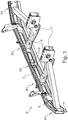
- FIG. 1 a device U for a motor vehicle according to an embodiment of the invention is shown, in particular a front underrun protection device U.
- the protective device U comprises a support structure 1 and a support structure 2 designed as a crossbeam construction.
- the support structure 1 serves to support the crossbeam construction 2 and to mount it to the lorry, in particular the chassis of the lorry.
- the support structure 1 and the cross member construction 2 are preferably welded together, but can also be attached to each other in other ways. It is even a one-piece design of support structure 1 and cross member construction 2 conceivable.
- the cross member construction 2 is provided with a panel 3, in particular a front panel 3.
- the support structure 1 and the cross member construction 2 are useful for receiving impact forces P1, P2 and P3 and in particular to meet the requirements of ECE-R93 with respect to impact loads.
- the panel 3, on the other hand, is useful for meeting dimensional requirements according to ECE-R93 and / or ECE-R61, preferably without additional caps, covers, etc.
- the panel 3 protrudes above and below the cross member structure 2 addition.
- the panel 3 is formed to the rear, to overlap the support structure 2 above and below or even to span completely back.
- the panel 3 may expediently protrude laterally beyond the cross member construction 2.
- the panel 3 is provided on its underside with a spoiler lip 4, which expediently extends along the underside of the panel 3.
- the panel 3 comprises on its upper side two line holders 5 for holding one or more lines.
- the panel 3 may comprise one or more fastening clips or one or more thread inserts, for the purpose of fitting one or more attachments.
- the panel 3 may be suitably releasably mounted by means of releasable fastening means to the support structure in order to be mounted and dismantled expedient in a simple manner.
- the panel 3 and the cross member construction 2 comprise a plurality of cavities (recesses, holes, depressions, openings and / or recesses), some of which are in FIG. 1 are provided with the reference numeral 6.
- One or more of the cavities 6 is usable for receiving one or more, in the FIG. 1 not shown container for media, eg. As air, water, etc.
Landscapes
- Engineering & Computer Science (AREA)
- Mechanical Engineering (AREA)
- Body Structure For Vehicles (AREA)
Abstract
Description
- Die Erfindung betrifft eine Vorrichtung, vorzugsweise eine Unterfahrschutzvorrichtung, für ein Kraftfahrzeug, insbesondere ein Nutzfahrzeug, wie z. B. einen Lastkraftwagen oder einen Omnibus.
- Aus der
DE 44 28 101 C2 ist bereits ein Front-Unterfahrschutzvorrichtung für einen Lastkraftwagen bekannt. Derartige Front-Unterfahrschutzvorrichtungen müssen insbesondere Vorgaben in Bezug auf Maße und Festigkeit (Kräfte, Aufpralllasten, etc.) nach der ECE-Regelung R93 (ECE-R93) erfüllen. In gewissen Einzelfällen müssen auch die Vorgaben der ECE-R61 erfüllt werden. In der Praxis ist es oftmals schwierig und aufwändig, eine Front-Unterfahrschutzvorrichtung zu schaffen, die einerseits die geforderten Maße und anderseits die geforderte Festigkeit erfüllt. - Eine Aufgabe der Erfindung ist es, eine Vorrichtung für ein Kraftfahrzeug zu schaffen, mittels der auf einfache Art und Weise einerseits Maßanforderungen und andererseits Festigkeitsanforderungen erfüllt werden können.
- Diese Aufgabe kann mit den Merkmalen des Hauptanspruchs gelöst werden. Vorteilhafte Weiterbildungen der Erfindung können den Unteransprüchen und der folgenden Beschreibung bevorzugter Ausführungsformen der Erfindungen entnommen werden.
- Die Erfindung schafft eine Vorrichtung, vorzugsweise eine Unterfahrschutzvorrichtung, für ein Kraftfahrzeug, insbesondere ein Nutzfahrzeug, z. B. einen Lastkraftwagen oder einen Omnibus. Die Unterfahrschutzvorrichtung ist vorzugsweise eine Front-Unterfahrschutzvorrichtung, kann aber auch z. B. eine Seiten- oder Heck-Unterfahrschutzvorrichtung sein.
- Die Vorrichtung umfasst eine Trägerkonstruktion, vorzugsweise eine Querträgerkonstruktion, und eine Tragstruktur zum Tragen der Trägerkonstruktion und zur Montage an das Kraftfahrzeug, vorzugsweise ein zwei Längsträger und zumindest einen Querträger umfassendes Chassis (z. B. Fahrgestell) des Kraftfahrzeugs.
- Die Tragstruktur und die Trägerkonstruktion können z. B. aneinander befestigt sein, z. B. mittels einer Schweißverbindung, Schraubverbindung, etc. Es ist sogar möglich, die Tragstruktur und die Trägerkonstruktion z. B. einstückig-integral zu gestalten.
- Die Vorrichtung zeichnet sich insbesondere dadurch aus, dass die Trägerkonstruktion mit zumindest einer Blende versehen ist, insbesondere mit einer Front-Blende. Die Blende kann zweckmäßig an die Trägerkonstruktion montiert und/oder aufgesetzt sein.
- Die Erfindung basiert insbesondere auf einer funktionellen Zweiteilung.
- Die Trägerkonstruktion und die Tragstruktur dienen zweckmäßig zur Aufnahme geforderter Kräfte, Aufpralllasten, etc. Die Blende hingegen dient zweckmäßig dazu, geforderte Maße zu erfüllen.
- Dadurch können auf vorteilhafte Art und Weise insbesondere Anforderungen gemäß der ECE-R93 erfüllt werden. Alternativ oder ergänzend können insbesondere Anforderungen gemäß der Außenkantenrichtlinie ECE-R61 erfüllt werden, vorzugsweise ohne eines oder mehrere Zusatzteile, wie Kappen, Deckel etc.
- Ebenfalls ist zweckmäßig eine hochkomplexe Formgebung z. B. nach Designvorschlägen möglich. Darüber hinaus kann die Vorrichtung preisgünstig hergestellt werden und ist gegenüber üblichen Unterfahrschutzvorrichtungen relativ leichtgewichtig.
- Die Blende kann z. B. seitlich, oben und/oder unten über die Trägerkonstruktion hinausragen.
- Es ist möglich, dass die Blende nach hinten geformt ist, z. B., um die Trägerkonstruktion seitlich, oben und/oder unten zu überlappen.
- Die Blende kann insbesondere mit einer Spoilerlippe versehen sein.
- Die Spoilerlippe erstreckt sich vorzugsweise entlang der Unterseite der Blende.
- Die Blende kann eine oder mehrere Leitungshalterungen zur Halterung einer oder mehrerer Leitungen umfassen, die z. B. an der Oberseite der Blende angeordnet sein können.
- Alternativ oder ergänzend kann die Blende zumindest einen Befestigungsclip oder zumindest ein Gewindeinsert umfassen, um vorzugsweise ein oder mehrere Anbauteile haltern zu können.
- Die Blende kann aus Kunststoff, Aluminium oder Stahl gefertigt sein.
- Die Trägerkonstruktion und/oder die Tragstruktur ist vorzugsweise aus Aluminium oder Stahl hergestellt.
- Die Blende ist vorzugsweise mittels lösbarer Befestigungsmittel lösbar an die Trägerkonstruktion montiert.
- Es ist möglich, dass die Blende und/oder die Trägerkonstruktion zumindest einen Hohlraum oder zumindest eine Aussparung aufweist. Der Hohlraum oder die Aussparung kann z. B. als Vertiefung, Loch, Öffnung, Ausnehmung und/oder Durchgangsloch ausgebildet sein.
- Vorzugsweise ist in dem Hohlraum oder der Aussparung der Blende und/oder der Trägerkonstruktion zumindest ein Behälter für ein Medium, z. B. Luft, Wasser, etc. zumindest abschnittsweise aufgenommen, insbesondere integriert.
- Die Blende weist vorzugsweise mehrere Versteifungsrippen auf.
- Im Rahmen der Erfindung kann die Vorrichtung als z. B. vorderer oder hinterer Querträger dienen, z. B. Schlussquerträger. Alternativ oder ergänzend ist auch eine seitliche Montage an das Kraftfahrzeug möglich, so dass sich die Trägerkonstruktion zweckmäßig im Wesentlichen in Längsrichtung des Kraftfahrzeugs erstreckt.
- Vorzugsweise ist die Vorrichtung aber als Unterfahrschutzvorrichtung ausgeführt, vorzugsweise als Front-Unterfahrschutzvorrichtung.
- Die Querträgerkonstruktion erstreckt sich vorzugsweise im Wesentlichen in Querrichtung des Kraftfahrzeugs.
- Die Erfindung ist nicht auf eine Vorrichtung wie hierin beschrieben beschränkt, sondern umfasst auch ein Kraftfahrzeug mit zumindest einer solchen Vorrichtung.
- Das Kraftfahrzeug ist vorzugsweise ein Nutzfahrzeug, z. B. ein Lastkraftwagen oder ein Omnibus.
- Die vorstehend beschriebenen bevorzugten Ausführungsformen und Merkmale der Erfindung sind miteinander kombinierbar. Andere vorteilhafte Weiterbildungen der Erfindung sind in den Unteransprüchen offenbart oder ergeben sich aus der folgenden Beschreibung bevorzugter Ausführungsformen der Erfindung in Verbindung mit der beigefügten Figur.
- Figur 1
- zeigt eine perspektivische Ansicht einer Vorrichtung gemäß einer Ausführungsform der Erfindung.
- In
Figur 1 ist eine Vorrichtung U für ein Kraftfahrzeug gemäß einer Ausführungsform der Erfindung gezeigt, insbesondere eine Front-Unterfahrschutzvorrichtung U. - Die Schutzvorrichtung U umfasst eine Tragstruktur 1 und eine als Querträgerkonstruktion ausgeführte Trägerkonstruktion 2. Die Tragstruktur 1 dient zum Tragen der Querträgerkonstruktion 2 und zur Montage an den Lastkraftwagen, insbesondere das Chassis des Lastkraftwagens. Die Tragstruktur 1 und die Querträgerkonstruktion 2 sind vorzugsweise miteinander verschweißt, können aber auch auf andere Art und Weise aneinander befestigt werden. Es ist sogar eine einteilige Ausführung aus Tragstruktur 1 und Querträgerkonstruktion 2 denkbar.
- Die Querträgerkonstruktion 2 ist mit einer Blende 3, insbesondere einer Front-Blende 3 versehen.
- Die Tragstruktur 1 und die Querträgerkonstruktion 2 dienen zweckmäßig zur Aufnahme von Aufprallkräften P1, P2 und P3 und insbesondere dazu, die Anforderungen gemäß ECE-R93 in Bezug auf Aufprallasten zu erfüllen. Die Blende 3 hingegen dient zweckmäßig dazu, Maßanforderungen gemäß ECE-R93 und/oder ECE-R61 zu erfüllen, vorzugsweise ohne zusätzliche Kappen, Deckel, etc.
- Die Blende 3 ragt oben und unten über die Querträgerkonstruktion 2 hinaus. Zudem ist die Blende 3 nach hinten geformt, um die Trägerkonstruktion 2 oben und unten zu überlappen oder gar gänzlich rückseitig zu überspannen. Die Blende 3 kann zweckmäßig auch seitlich über die Querträgerkonstruktion 2 hinausragen.
- Die Blende 3 ist an ihrer Unterseite mit einer Spoilerlippe 4 versehen, die sich zweckmäßig entlang der Unterseite der Blende 3 erstreckt.
- Darüber hinaus umfasst die Blende 3 an ihrer Oberseite zwei Leitungshalterungen 5 zur Halterung einer oder mehrerer Leitungen. Alternativ oder ergänzend kann die Blende 3 einen oder mehrere Befestigungsclips oder ein oder mehrere Gewindeinserts umfassen, zur zweckmäßigen Montage eines oder mehrerer Anbauteile.
- Die Blende 3 kann zweckmäßig mittels lösbaren Befestigungsmitteln lösbar an die Trägerkonstruktion montiert sein, um zweckmäßig auf einfache Art und Weise montiert und demontiert werden zu können.
- Die Blende 3 und die Querträgerkonstruktion 2 umfassen mehrere Hohlräume (Aussparungen, Löcher, Vertiefungen, Öffnungen und/oder Ausnehmungen), von denen einige in
Figur 1 mit dem Bezugszeichen 6 versehen sind. Einer oder mehrere der Hohlräume 6 ist nutzbar zur Aufnahme eines oder mehrerer, in derFigur 1 nicht gezeigter Behälter für Medien, z. B. Luft, Wasser, etc. - Die Erfindung ist nicht auf die oben beschriebenen bevorzugten Ausführungsformen beschränkt. Vielmehr ist eine Vielzahl von Varianten und Abwandlungen möglich, die ebenfalls von dem Erfindungsgedanken Gebrauch machen und deshalb in den Schutzbereich fallen. Darüber hinaus beansprucht die Erfindung auch Schutz für den Gegenstand und die Merkmale der Unteransprüche unabhängig von den in Bezug genommenen Merkmalen und Ansprüchen.
-
- 1
- Tragstruktur
- 2
- Trägerkonstruktion, insbesondere Querträgerkonstruktion
- 3
- Blende
- 4
- Spoilerlippe
- 5
- Leitungshalterung
- 6
- Hohlraum/Aussparung
- P1, P2, P3
- Kräfte, insbesondere Aufpralllasten
- U
- Vorrichtung, zweckmäßig Unterfahrschutzvorrichtung, insbesondere hinten, vorne und/oder seitlich
Claims (15)
- Vorrichtung (U), vorzugsweise Unterfahrschutzvorrichtung (U), für ein Kraftfahrzeug, mit einer Trägerkonstruktion (2), vorzugsweise einer Querträgerkonstruktion (2), und einer Tragstruktur (1) zum Tragen der Trägerkonstruktion (2) und zur Montage an das Kraftfahrzeug, dadurch gekennzeichnet, dass die Trägerkonstruktion (2) mit einer Blende (3) versehen ist.
- Vorrichtung (U) nach Anspruch 1, dadurch gekennzeichnet, dass die Blende (3) seitlich, oben und/oder unten über die Trägerkonstruktion (2) hinausragt.
- Vorrichtung (U) nach Anspruch 1 oder 2, dadurch gekennzeichnet, dass die Blende (3) nach hinten geformt ist, vorzugsweise, um die Trägerkonstruktion (2) seitlich, oben und/oder unten zu überlappen.
- Vorrichtung (U) nach einem der vorhergehenden Ansprüche, dadurch gekennzeichnet, dass die Blende (3) eine Spoilerlippe (4) umfasst und vorzugsweise sich die Spoilerlippe (4) entlang der Unterseite der Blende (3) erstreckt.
- Vorrichtung (U) nach einem der vorhergehenden Ansprüche, dadurch gekennzeichnet, dass die Blende (3) zumindest eine Leitungshalterung (5) zur Halterung einer Leitung umfasst und vorzugsweise die Leitungshalterung (5) an der Oberseite der Blende (3) angeordnet ist.
- Vorrichtung (U) nach einem der vorhergehenden Ansprüche, dadurch gekennzeichnet, dass die Blende (3) zumindest einen Befestigungsclip oder zumindest ein Gewindeinsert umfasst.
- Vorrichtung (U) nach einem der vorhergehenden Ansprüche, dadurch gekennzeichnet, dass die Blende (3) aus Kunststoff, Aluminium oder Stahl gefertigt ist.
- Vorrichtung (U) nach einem der vorhergehenden Ansprüche, dadurch gekennzeichnet, dass die Trägerkonstruktion (2) und/oder die Tragstruktur (1) aus Aluminium oder Stahl gefertigt ist.
- Vorrichtung (U) nach einem der vorhergehenden Ansprüche, dadurch gekennzeichnet, dass die Blende (3) mittels lösbaren Befestigungsmitteln lösbar an die Trägerkonstruktion (2) montiert ist.
- Vorrichtung (U) nach einem der vorhergehenden Ansprüche, dadurch gekennzeichnet, dass die Blende (3) und/oder die Trägerkonstruktion (2) zumindest einen Hohlraum oder zumindest eine Aussparung (6) aufweist.
- Vorrichtung (U) nach Anspruch 10, dadurch gekennzeichnet, dass in dem Hohlraum oder der Aussparung (6) zumindest abschnittsweise zumindest ein Behälter für ein Medium aufgenommen ist.
- Vorrichtung (U) nach einem der vorhergehenden Ansprüche, dadurch gekennzeichnet, dass die Trägerkonstruktion (2) und die Tragstruktur (1) zur Aufnahme von Aufpralllasten dienen und/oder die Blende (3) zur Maßeinhaltung dient.
- Vorrichtung (U) nach einem der vorhergehenden Ansprüche, dadurch gekennzeichnet, dass die Blende (3) Versteifungsrippen aufweist.
- Vorrichtung (U) nach einem der vorhergehenden Ansprüche, dadurch gekennzeichnet, dass die Trägerkonstruktion (2) eine sich in Querrichtung des Kraftfahrzeugs erstreckende Querträgerkonstruktion ist und die Vorrichtung (U) eine Front-Unterfahrschutzvorrichtung ist.
- Kraftfahrzeug, vorzugsweise Nutzfahrzeug, mit zumindest einer Vorrichtung (U) nach einem der vorhergehenden Ansprüche.
Applications Claiming Priority (1)
| Application Number | Priority Date | Filing Date | Title |
|---|---|---|---|
| DE102016002510.7A DE102016002510A1 (de) | 2016-03-01 | 2016-03-01 | Vorrichtung, insbesondere Unterfahrschutzvorrichtung, für ein Kraftfahrzeug |
Publications (3)
| Publication Number | Publication Date |
|---|---|
| EP3213966A1 true EP3213966A1 (de) | 2017-09-06 |
| EP3213966B1 EP3213966B1 (de) | 2019-06-19 |
| EP3213966B8 EP3213966B8 (de) | 2019-07-31 |
Family
ID=57914666
Family Applications (1)
| Application Number | Title | Priority Date | Filing Date |
|---|---|---|---|
| EP17000114.3A Active EP3213966B8 (de) | 2016-03-01 | 2017-01-20 | Vorrichtung, insbesondere unterfahrschutzvorrichtung, für ein kraftfahrzeug |
Country Status (2)
| Country | Link |
|---|---|
| EP (1) | EP3213966B8 (de) |
| DE (1) | DE102016002510A1 (de) |
Cited By (1)
| Publication number | Priority date | Publication date | Assignee | Title |
|---|---|---|---|---|
| US20230382333A1 (en) * | 2022-05-31 | 2023-11-30 | Subaru Corporation | Vehicle body front structure |
Citations (5)
| Publication number | Priority date | Publication date | Assignee | Title |
|---|---|---|---|---|
| DE10129066A1 (de) * | 2001-06-15 | 2002-12-19 | Solvay Automotive Gmbh | Stoßfängerschürze mit in diesem Bereich vorgesehenem Flüssigkeitsbehälter |
| DE4428101C2 (de) | 1994-08-09 | 2003-07-10 | Daimler Chrysler Ag | Rahmenkopf für einen Tragrahmen eines Lastkraftwagens |
| DE102008023241A1 (de) * | 2008-05-10 | 2009-11-19 | Faurecia Autositze Gmbh | Kabelhalterung für die Halterung von Kabeln in Fahrzeugen |
| DE202013002033U1 (de) * | 2013-03-01 | 2013-03-19 | GM Global Technology Operations LLC (n. d. Ges. d. Staates Delaware) | Frontpartie für ein Kraftfahrzeug |
| EP2821293A1 (de) * | 2013-07-05 | 2015-01-07 | Oy Parlok Ab | Klammeranordnung, Seitenwandanordnung für ein Fahrzeug und Verfahren zum Nachrüsten einer Seitenwand |
Family Cites Families (5)
| Publication number | Priority date | Publication date | Assignee | Title |
|---|---|---|---|---|
| DE9017550U1 (de) * | 1990-12-28 | 1991-04-04 | Elble, Albert, 7616 Zell | Anfahrschutz für Lastkraftwagen, insbesondere Sattelauflieger von Sattelschleppern |
| DE4317391A1 (de) * | 1993-05-25 | 1994-12-01 | Marita Klix | Kombinierter Kraftfahrzeugwerbeträger/Unterfahrschutz |
| DE10112424A1 (de) * | 2001-03-15 | 2002-09-26 | Daimler Chrysler Ag | Kraftwagenbug mit einer Stoßfängereinheit |
| DE102004026280A1 (de) * | 2004-05-28 | 2005-12-15 | Man Nutzfahrzeuge Ag | Stossfängereinheit für einen Frontbereich eines Kraftfahrzeugs |
| DE102011010200A1 (de) * | 2011-02-03 | 2012-02-16 | Daimler Ag | Unterfahrschutzeinrichtung für ein Nutzfahrzeug |
-
2016
- 2016-03-01 DE DE102016002510.7A patent/DE102016002510A1/de not_active Withdrawn
-
2017
- 2017-01-20 EP EP17000114.3A patent/EP3213966B8/de active Active
Patent Citations (5)
| Publication number | Priority date | Publication date | Assignee | Title |
|---|---|---|---|---|
| DE4428101C2 (de) | 1994-08-09 | 2003-07-10 | Daimler Chrysler Ag | Rahmenkopf für einen Tragrahmen eines Lastkraftwagens |
| DE10129066A1 (de) * | 2001-06-15 | 2002-12-19 | Solvay Automotive Gmbh | Stoßfängerschürze mit in diesem Bereich vorgesehenem Flüssigkeitsbehälter |
| DE102008023241A1 (de) * | 2008-05-10 | 2009-11-19 | Faurecia Autositze Gmbh | Kabelhalterung für die Halterung von Kabeln in Fahrzeugen |
| DE202013002033U1 (de) * | 2013-03-01 | 2013-03-19 | GM Global Technology Operations LLC (n. d. Ges. d. Staates Delaware) | Frontpartie für ein Kraftfahrzeug |
| EP2821293A1 (de) * | 2013-07-05 | 2015-01-07 | Oy Parlok Ab | Klammeranordnung, Seitenwandanordnung für ein Fahrzeug und Verfahren zum Nachrüsten einer Seitenwand |
Cited By (2)
| Publication number | Priority date | Publication date | Assignee | Title |
|---|---|---|---|---|
| US20230382333A1 (en) * | 2022-05-31 | 2023-11-30 | Subaru Corporation | Vehicle body front structure |
| US12472897B2 (en) * | 2022-05-31 | 2025-11-18 | Subaru Corporation | Vehicle body front structure |
Also Published As
| Publication number | Publication date |
|---|---|
| DE102016002510A1 (de) | 2017-09-07 |
| EP3213966B8 (de) | 2019-07-31 |
| EP3213966B1 (de) | 2019-06-19 |
Similar Documents
| Publication | Publication Date | Title |
|---|---|---|
| DE102009052920A1 (de) | Hilfsträger | |
| DE102009012057A1 (de) | Vorrichtung zum Aufnehmen von Seitenkräften | |
| EP1880784A2 (de) | Verbund aus einem Leichtmetallgussbauteil und einem Stahlbauteil | |
| DE102016212297A1 (de) | Kraftfahrzeug | |
| EP2399782B1 (de) | Traggestell zur seitlichen Befestigung von Anbauteilen an einem Längsträger einer Nutzfahrzeug-Tragstruktur | |
| DE102014214913B4 (de) | Längsträgervorrichtung zum Tragen eines Frontmotors in einem Kraftfahrzeug | |
| DE202014101186U1 (de) | Hydrogeformte Verstärkung vom Dachpaneel zu einer Seitensäule für Fahrzeuge | |
| DE102010006976A1 (de) | Kraftfahrzeug-Vorderbau | |
| EP3339107B1 (de) | Heckunterfahrschutz für ein fahrzeug | |
| EP3213966B1 (de) | Vorrichtung, insbesondere unterfahrschutzvorrichtung, für ein kraftfahrzeug | |
| DE102008020051A1 (de) | Crashbox für eine Karosserie eines Kraftwagens | |
| DE102017005773A1 (de) | Fahrzeug | |
| DE102004057214A1 (de) | Frontbereich einer Verkleidung eines Kraftfahrzeuges, mit einem Stoßabsorberelement für den Frontbereich | |
| DE2107701A1 (de) | Stoßfänger für Kraftfahrzeuge | |
| DE202019102613U1 (de) | Dachrahmenhalterungsbaugruppe | |
| EP3339106B1 (de) | Heckunterfahrschutz für ein fahrzeug | |
| EP2945827B1 (de) | Montagevorrichtung für ein seitenwandverkleidungselement eines schienenfahrzeugs | |
| DE102005015855B3 (de) | Nutzfahrzeug | |
| DE102006056225A1 (de) | Halteeinrichtung für einen Lastkraftwagen | |
| DE102015224098B4 (de) | Schienensystem und Fahrzeug mit einem derartigen Schienensystem | |
| EP3130528B1 (de) | Seitenverkleidungseinrichtung für ein nutzfahrzeug | |
| DE102015202420A1 (de) | Türinnenverkleidung, Fahrzeugtür mit einer Türinnenverkleidung sowie Fahrzeug mit einer Fahrzeugtür | |
| EP3617041A1 (de) | Fahrerhaus für ein nutzfahrzeug | |
| DE102008052226A1 (de) | Querträger für ein Kraftfahrzeug | |
| DE102014004335A1 (de) | Karosseriestruktur für ein Kraftfahrzeug |
Legal Events
| Date | Code | Title | Description |
|---|---|---|---|
| PUAI | Public reference made under article 153(3) epc to a published international application that has entered the european phase |
Free format text: ORIGINAL CODE: 0009012 |
|
| STAA | Information on the status of an ep patent application or granted ep patent |
Free format text: STATUS: THE APPLICATION HAS BEEN PUBLISHED |
|
| AK | Designated contracting states |
Kind code of ref document: A1 Designated state(s): AL AT BE BG CH CY CZ DE DK EE ES FI FR GB GR HR HU IE IS IT LI LT LU LV MC MK MT NL NO PL PT RO RS SE SI SK SM TR |
|
| AX | Request for extension of the european patent |
Extension state: BA ME |
|
| STAA | Information on the status of an ep patent application or granted ep patent |
Free format text: STATUS: REQUEST FOR EXAMINATION WAS MADE |
|
| 17P | Request for examination filed |
Effective date: 20180122 |
|
| RBV | Designated contracting states (corrected) |
Designated state(s): AL AT BE BG CH CY CZ DE DK EE ES FI FR GB GR HR HU IE IS IT LI LT LU LV MC MK MT NL NO PL PT RO RS SE SI SK SM TR |
|
| STAA | Information on the status of an ep patent application or granted ep patent |
Free format text: STATUS: EXAMINATION IS IN PROGRESS |
|
| 17Q | First examination report despatched |
Effective date: 20180606 |
|
| GRAP | Despatch of communication of intention to grant a patent |
Free format text: ORIGINAL CODE: EPIDOSNIGR1 |
|
| STAA | Information on the status of an ep patent application or granted ep patent |
Free format text: STATUS: GRANT OF PATENT IS INTENDED |
|
| INTG | Intention to grant announced |
Effective date: 20190205 |
|
| GRAS | Grant fee paid |
Free format text: ORIGINAL CODE: EPIDOSNIGR3 |
|
| GRAA | (expected) grant |
Free format text: ORIGINAL CODE: 0009210 |
|
| STAA | Information on the status of an ep patent application or granted ep patent |
Free format text: STATUS: THE PATENT HAS BEEN GRANTED |
|
| AK | Designated contracting states |
Kind code of ref document: B1 Designated state(s): AL AT BE BG CH CY CZ DE DK EE ES FI FR GB GR HR HU IE IS IT LI LT LU LV MC MK MT NL NO PL PT RO RS SE SI SK SM TR |
|
| REG | Reference to a national code |
Ref country code: GB Ref legal event code: FG4D Free format text: NOT ENGLISH |
|
| REG | Reference to a national code |
Ref country code: CH Ref legal event code: EP |
|
| REG | Reference to a national code |
Ref country code: IE Ref legal event code: FG4D Free format text: LANGUAGE OF EP DOCUMENT: GERMAN |
|
| REG | Reference to a national code |
Ref country code: DE Ref legal event code: R096 Ref document number: 502017001549 Country of ref document: DE |
|
| REG | Reference to a national code |
Ref country code: AT Ref legal event code: REF Ref document number: 1145078 Country of ref document: AT Kind code of ref document: T Effective date: 20190715 Ref country code: CH Ref legal event code: PK Free format text: BERICHTIGUNG B8 |
|
| RAP2 | Party data changed (patent owner data changed or rights of a patent transferred) |
Owner name: MAN TRUCK & BUS SE |
|
| REG | Reference to a national code |
Ref country code: NL Ref legal event code: FP |
|
| REG | Reference to a national code |
Ref country code: SE Ref legal event code: TRGR |
|
| REG | Reference to a national code |
Ref country code: AT Ref legal event code: HC Ref document number: 1145078 Country of ref document: AT Kind code of ref document: T Owner name: MAN TRUCK & BUS SE, DE Effective date: 20190826 |
|
| PG25 | Lapsed in a contracting state [announced via postgrant information from national office to epo] |
Ref country code: LT Free format text: LAPSE BECAUSE OF FAILURE TO SUBMIT A TRANSLATION OF THE DESCRIPTION OR TO PAY THE FEE WITHIN THE PRESCRIBED TIME-LIMIT Effective date: 20190619 Ref country code: AL Free format text: LAPSE BECAUSE OF FAILURE TO SUBMIT A TRANSLATION OF THE DESCRIPTION OR TO PAY THE FEE WITHIN THE PRESCRIBED TIME-LIMIT Effective date: 20190619 Ref country code: NO Free format text: LAPSE BECAUSE OF FAILURE TO SUBMIT A TRANSLATION OF THE DESCRIPTION OR TO PAY THE FEE WITHIN THE PRESCRIBED TIME-LIMIT Effective date: 20190919 Ref country code: FI Free format text: LAPSE BECAUSE OF FAILURE TO SUBMIT A TRANSLATION OF THE DESCRIPTION OR TO PAY THE FEE WITHIN THE PRESCRIBED TIME-LIMIT Effective date: 20190619 Ref country code: HR Free format text: LAPSE BECAUSE OF FAILURE TO SUBMIT A TRANSLATION OF THE DESCRIPTION OR TO PAY THE FEE WITHIN THE PRESCRIBED TIME-LIMIT Effective date: 20190619 |
|
| REG | Reference to a national code |
Ref country code: LT Ref legal event code: MG4D |
|
| PG25 | Lapsed in a contracting state [announced via postgrant information from national office to epo] |
Ref country code: LV Free format text: LAPSE BECAUSE OF FAILURE TO SUBMIT A TRANSLATION OF THE DESCRIPTION OR TO PAY THE FEE WITHIN THE PRESCRIBED TIME-LIMIT Effective date: 20190619 Ref country code: GR Free format text: LAPSE BECAUSE OF FAILURE TO SUBMIT A TRANSLATION OF THE DESCRIPTION OR TO PAY THE FEE WITHIN THE PRESCRIBED TIME-LIMIT Effective date: 20190920 Ref country code: BG Free format text: LAPSE BECAUSE OF FAILURE TO SUBMIT A TRANSLATION OF THE DESCRIPTION OR TO PAY THE FEE WITHIN THE PRESCRIBED TIME-LIMIT Effective date: 20190919 Ref country code: RS Free format text: LAPSE BECAUSE OF FAILURE TO SUBMIT A TRANSLATION OF THE DESCRIPTION OR TO PAY THE FEE WITHIN THE PRESCRIBED TIME-LIMIT Effective date: 20190619 |
|
| PG25 | Lapsed in a contracting state [announced via postgrant information from national office to epo] |
Ref country code: SK Free format text: LAPSE BECAUSE OF FAILURE TO SUBMIT A TRANSLATION OF THE DESCRIPTION OR TO PAY THE FEE WITHIN THE PRESCRIBED TIME-LIMIT Effective date: 20190619 Ref country code: RO Free format text: LAPSE BECAUSE OF FAILURE TO SUBMIT A TRANSLATION OF THE DESCRIPTION OR TO PAY THE FEE WITHIN THE PRESCRIBED TIME-LIMIT Effective date: 20190619 Ref country code: CZ Free format text: LAPSE BECAUSE OF FAILURE TO SUBMIT A TRANSLATION OF THE DESCRIPTION OR TO PAY THE FEE WITHIN THE PRESCRIBED TIME-LIMIT Effective date: 20190619 Ref country code: PT Free format text: LAPSE BECAUSE OF FAILURE TO SUBMIT A TRANSLATION OF THE DESCRIPTION OR TO PAY THE FEE WITHIN THE PRESCRIBED TIME-LIMIT Effective date: 20191021 Ref country code: EE Free format text: LAPSE BECAUSE OF FAILURE TO SUBMIT A TRANSLATION OF THE DESCRIPTION OR TO PAY THE FEE WITHIN THE PRESCRIBED TIME-LIMIT Effective date: 20190619 |
|
| PG25 | Lapsed in a contracting state [announced via postgrant information from national office to epo] |
Ref country code: ES Free format text: LAPSE BECAUSE OF FAILURE TO SUBMIT A TRANSLATION OF THE DESCRIPTION OR TO PAY THE FEE WITHIN THE PRESCRIBED TIME-LIMIT Effective date: 20190619 Ref country code: IS Free format text: LAPSE BECAUSE OF FAILURE TO SUBMIT A TRANSLATION OF THE DESCRIPTION OR TO PAY THE FEE WITHIN THE PRESCRIBED TIME-LIMIT Effective date: 20191019 Ref country code: SM Free format text: LAPSE BECAUSE OF FAILURE TO SUBMIT A TRANSLATION OF THE DESCRIPTION OR TO PAY THE FEE WITHIN THE PRESCRIBED TIME-LIMIT Effective date: 20190619 |
|
| PG25 | Lapsed in a contracting state [announced via postgrant information from national office to epo] |
Ref country code: TR Free format text: LAPSE BECAUSE OF FAILURE TO SUBMIT A TRANSLATION OF THE DESCRIPTION OR TO PAY THE FEE WITHIN THE PRESCRIBED TIME-LIMIT Effective date: 20190619 |
|
| PG25 | Lapsed in a contracting state [announced via postgrant information from national office to epo] |
Ref country code: PL Free format text: LAPSE BECAUSE OF FAILURE TO SUBMIT A TRANSLATION OF THE DESCRIPTION OR TO PAY THE FEE WITHIN THE PRESCRIBED TIME-LIMIT Effective date: 20190619 Ref country code: DK Free format text: LAPSE BECAUSE OF FAILURE TO SUBMIT A TRANSLATION OF THE DESCRIPTION OR TO PAY THE FEE WITHIN THE PRESCRIBED TIME-LIMIT Effective date: 20190619 |
|
| PG25 | Lapsed in a contracting state [announced via postgrant information from national office to epo] |
Ref country code: IS Free format text: LAPSE BECAUSE OF FAILURE TO SUBMIT A TRANSLATION OF THE DESCRIPTION OR TO PAY THE FEE WITHIN THE PRESCRIBED TIME-LIMIT Effective date: 20200224 |
|
| REG | Reference to a national code |
Ref country code: DE Ref legal event code: R097 Ref document number: 502017001549 Country of ref document: DE |
|
| PLBE | No opposition filed within time limit |
Free format text: ORIGINAL CODE: 0009261 |
|
| STAA | Information on the status of an ep patent application or granted ep patent |
Free format text: STATUS: NO OPPOSITION FILED WITHIN TIME LIMIT |
|
| PG2D | Information on lapse in contracting state deleted |
Ref country code: IS |
|
| 26N | No opposition filed |
Effective date: 20200603 |
|
| PG25 | Lapsed in a contracting state [announced via postgrant information from national office to epo] |
Ref country code: SI Free format text: LAPSE BECAUSE OF FAILURE TO SUBMIT A TRANSLATION OF THE DESCRIPTION OR TO PAY THE FEE WITHIN THE PRESCRIBED TIME-LIMIT Effective date: 20190619 Ref country code: MC Free format text: LAPSE BECAUSE OF FAILURE TO SUBMIT A TRANSLATION OF THE DESCRIPTION OR TO PAY THE FEE WITHIN THE PRESCRIBED TIME-LIMIT Effective date: 20190619 |
|
| REG | Reference to a national code |
Ref country code: CH Ref legal event code: PL |
|
| REG | Reference to a national code |
Ref country code: BE Ref legal event code: MM Effective date: 20200131 |
|
| PG25 | Lapsed in a contracting state [announced via postgrant information from national office to epo] |
Ref country code: LU Free format text: LAPSE BECAUSE OF NON-PAYMENT OF DUE FEES Effective date: 20200120 |
|
| PG25 | Lapsed in a contracting state [announced via postgrant information from national office to epo] |
Ref country code: LI Free format text: LAPSE BECAUSE OF NON-PAYMENT OF DUE FEES Effective date: 20200131 Ref country code: CH Free format text: LAPSE BECAUSE OF NON-PAYMENT OF DUE FEES Effective date: 20200131 Ref country code: BE Free format text: LAPSE BECAUSE OF NON-PAYMENT OF DUE FEES Effective date: 20200131 |
|
| PG25 | Lapsed in a contracting state [announced via postgrant information from national office to epo] |
Ref country code: IE Free format text: LAPSE BECAUSE OF NON-PAYMENT OF DUE FEES Effective date: 20200120 |
|
| GBPC | Gb: european patent ceased through non-payment of renewal fee |
Effective date: 20210120 |
|
| PG25 | Lapsed in a contracting state [announced via postgrant information from national office to epo] |
Ref country code: GB Free format text: LAPSE BECAUSE OF NON-PAYMENT OF DUE FEES Effective date: 20210120 |
|
| PG25 | Lapsed in a contracting state [announced via postgrant information from national office to epo] |
Ref country code: MT Free format text: LAPSE BECAUSE OF FAILURE TO SUBMIT A TRANSLATION OF THE DESCRIPTION OR TO PAY THE FEE WITHIN THE PRESCRIBED TIME-LIMIT Effective date: 20190619 Ref country code: CY Free format text: LAPSE BECAUSE OF FAILURE TO SUBMIT A TRANSLATION OF THE DESCRIPTION OR TO PAY THE FEE WITHIN THE PRESCRIBED TIME-LIMIT Effective date: 20190619 |
|
| PG25 | Lapsed in a contracting state [announced via postgrant information from national office to epo] |
Ref country code: MK Free format text: LAPSE BECAUSE OF FAILURE TO SUBMIT A TRANSLATION OF THE DESCRIPTION OR TO PAY THE FEE WITHIN THE PRESCRIBED TIME-LIMIT Effective date: 20190619 |
|
| REG | Reference to a national code |
Ref country code: AT Ref legal event code: MM01 Ref document number: 1145078 Country of ref document: AT Kind code of ref document: T Effective date: 20220120 |
|
| PG25 | Lapsed in a contracting state [announced via postgrant information from national office to epo] |
Ref country code: AT Free format text: LAPSE BECAUSE OF NON-PAYMENT OF DUE FEES Effective date: 20220120 |
|
| PGFP | Annual fee paid to national office [announced via postgrant information from national office to epo] |
Ref country code: NL Payment date: 20260122 Year of fee payment: 10 |
|
| PGFP | Annual fee paid to national office [announced via postgrant information from national office to epo] |
Ref country code: SE Payment date: 20260126 Year of fee payment: 10 |
|
| PGFP | Annual fee paid to national office [announced via postgrant information from national office to epo] |
Ref country code: DE Payment date: 20260127 Year of fee payment: 10 |
|
| PGFP | Annual fee paid to national office [announced via postgrant information from national office to epo] |
Ref country code: IT Payment date: 20260123 Year of fee payment: 10 |
|
| PGFP | Annual fee paid to national office [announced via postgrant information from national office to epo] |
Ref country code: FR Payment date: 20260127 Year of fee payment: 10 |