EP2945827B1 - Montagevorrichtung für ein seitenwandverkleidungselement eines schienenfahrzeugs - Google Patents
Montagevorrichtung für ein seitenwandverkleidungselement eines schienenfahrzeugs Download PDFInfo
- Publication number
- EP2945827B1 EP2945827B1 EP14707735.8A EP14707735A EP2945827B1 EP 2945827 B1 EP2945827 B1 EP 2945827B1 EP 14707735 A EP14707735 A EP 14707735A EP 2945827 B1 EP2945827 B1 EP 2945827B1
- Authority
- EP
- European Patent Office
- Prior art keywords
- side wall
- rail vehicle
- cladding element
- rail
- wall cladding
- Prior art date
- Legal status (The legal status is an assumption and is not a legal conclusion. Google has not performed a legal analysis and makes no representation as to the accuracy of the status listed.)
- Active
Links
- 238000005253 cladding Methods 0.000 title claims description 68
- 230000000295 complement effect Effects 0.000 claims description 8
- 238000007789 sealing Methods 0.000 description 5
- 238000011161 development Methods 0.000 description 4
- 230000018109 developmental process Effects 0.000 description 4
- 230000001419 dependent effect Effects 0.000 description 1
- 238000006073 displacement reaction Methods 0.000 description 1
- 230000005489 elastic deformation Effects 0.000 description 1
Images

Classifications
-
- B—PERFORMING OPERATIONS; TRANSPORTING
- B61—RAILWAYS
- B61D—BODY DETAILS OR KINDS OF RAILWAY VEHICLES
- B61D17/00—Construction details of vehicle bodies
-
- B—PERFORMING OPERATIONS; TRANSPORTING
- B61—RAILWAYS
- B61D—BODY DETAILS OR KINDS OF RAILWAY VEHICLES
- B61D1/00—Carriages for ordinary railway passenger traffic
-
- B—PERFORMING OPERATIONS; TRANSPORTING
- B61—RAILWAYS
- B61D—BODY DETAILS OR KINDS OF RAILWAY VEHICLES
- B61D17/00—Construction details of vehicle bodies
- B61D17/04—Construction details of vehicle bodies with bodies of metal; with composite, e.g. metal and wood body structures
- B61D17/18—Internal lining, e.g. insulating
Definitions
- the invention relates to a side wall cladding element for a rail vehicle and a rail vehicle with a side wall cladding element.
- the invention has for its object to propose an installation-friendly and vandalism-proof Sowandverliesbefestiqunq invisible from the passenger compartment of a rail vehicle.
- a rail vehicle according to the invention in particular a passenger rail vehicle, comprises a side wall cladding element with at least one hook and for fastening the side wall cladding element on a shell of the rail vehicle, a complementary to the at least one hook of the side wall covering element guide, which guide is connected to a shell of the rail vehicle, and which hook and which guide are configured for hooking the hook of the side wall covering element in the guide.
- a side wall cladding element with at least one hook and for fastening the side wall cladding element on a shell of the rail vehicle
- a complementary to the at least one hook of the side wall covering element guide which guide is connected to a shell of the rail vehicle, and which hook and which guide are configured for hooking the hook of the side wall covering element in the guide.
- the Hook of the side wall covering element is according to the invention hooked into the guide and thus the side wall lining element is connected to the shell of the rail vehicle.
- the guide is a rail so the sidewall lining element is freely positionable along the rail. It runs in particular parallel to the longitudinal axis of the rail vehicle.
- the hook is in particular designed such that it acts at least perpendicular to the side wall covering element, so that the side wall lining element is fixed at least in this direction to the shell of the rail vehicle. If the sidewall cladding element in turn is vertically aligned in the rail vehicle, the hook counteracts horizontal displacement of the sidewall cladding element away from the guide.
- the at least one hook of the side wall covering element on a spur which is arranged for hooking the guide between the spur and side wall cladding element spaced from the side wall cladding element.
- the spur of the hook is elastically deformable, in particular in a direction perpendicular to the side wall cladding element.
- the guide between the side wall cladding element and hook can be clamped.
- the hook acts like a spring, biasing it against the guide.
- the at least one hook of the side wall covering element is open at the bottom.
- the side wall cladding element is hooked from above into the guide and is accordingly mounted in the mounted state in the guide.
- the hook is hooked against the direction of the weight of the side wall panel member in the guide, that self-locking occurs and thus a decrease in the side wall panel member is blocked.
- the at least one hook of the side wall covering element is arranged at a lower end of the side wall lining element.
- at least two or more hooks for hooking and securing the side wall covering element in at least one complementary configured to the hook rail of the rail vehicle at the lower end of the side wall covering element are arranged for the own attachment of the side wall covering element.
- the side wall cladding element for cladding the side walls in the interior, in particular in the passenger compartment, of the rail vehicle extends in particular between the floor of the rail vehicle and a ceiling of the rail vehicle. As will be explained below, it may have a height that is greater than the distance between the ceiling and floor of the interior of the rail vehicle.
- the side wall cladding element for its own attachment to the rail vehicle comprises at least one first rail for free positioning of a first holder complementary to the first rail along the first rail and for fixing the first holder to the first rail.
- the first holder is initially free to position along the first rail and then connect to this position with the first rail, for example, by clamping the first holder to the first rail.
- the connection of the first rail and the first holder is designed so that it is suitable to attach the side wall lining element with the at least one first holder to a shell of the rail vehicle.
- the first holder is in turn connected to the shell of the rail vehicle, in particular detachably connected, for example by a screw connection.
- Of the first holder is initially freely positionable along the first rail of the side wall cladding element. It is particularly jammed with the rail, wedged or screwed and also detachably connected to the shell of the rail vehicle, for example by means of a screw.
- the shell has a limited number of positions for the arrangement of first holders.
- side wall cladding elements may be formed differently sized by the first profile rail and / or arranged variably along the longitudinal axis of the rail vehicle.
- the side wall cladding element For attachment of further cladding elements, in particular ceiling cladding elements, on the side wall cladding element, it may be at least one further, second rail for free positioning of a complementary to the second rail designed second holder along the second rail and for securing the second holder at the freely selected position of the second Have profile rail.
- the sidewall cladding element comprises both the first and second rails, whereby the further cladding elements are attached to the sidewall cladding element and thereby to the body shell of the rail vehicle via the sidewall cladding element.
- the first and / or the second rail are advantageously arranged parallel to the longitudinal axis of the rail vehicle. Further developed, the first and / or the second rail in cross-section C-shaped configured. If the first C-shaped profiled rail has a vertically oriented C-shaped opening and / or the second C-shaped profiled rail has a horizontally oriented C-shaped opening, then the opening of the first profiled rail is in particular upwards and / or the opening of the second rail has to the side, in particular into the interior of the Rail vehicle, so that the first holder is inserted from above into the first rail and in particular guided along the longitudinal axis of the rail vehicle in the first rail and / or the second holder is inserted from above into the second rail and in particular along the longitudinal axis of the rail vehicle in the second rail is guided.
- first and / or the second rail are arranged at the upper end of the side wall lining element.
- first rail and the second rail are cohesively connected to each other, in particular joint-free.
- Monolithically formed they are for example the fact that they are made of a single cast, in particular both the first and the second rail are made of an extruded profile.
- both the individual, first holder and the first profile rail are dimensioned such that they support the side wall lining element with a predetermined mass alone.
- two or more first holders for fastening the side wall lining element are connected to the first rail and the shell of the rail vehicle.
- the sidewall cladding element may be fastened to multiple sections of a first component of a two-part velcro fastener be provided, in particular in vertically arranged strips, in particular on the sides or edges of the side wall lining element, in particular along its vertical axis, perpendicular to the longitudinal axis of the rail vehicle.
- Sections of the other, second component of the hook and loop fastener are then arranged on the shell, for example on door and / or window columns, respectively.
- the first sections of the first component of the hook-and-loop fastener are arranged on a rear side of the side wall lining element facing away from the interior, in particular the passenger compartment, of the rail vehicle.
- the second sections of the second component of the hook and loop fastener are correspondingly mounted on a side of the shell in the vehicle interior.
- the side wall cladding element is introduced by being hooked into the lower rail during assembly, it can subsequently be fastened to the shell with the hook-and-loop fasteners in order to subsequently fix it to the rail vehicle with the first brackets.
- a refinement of the rail vehicle according to the invention provides that the rail vehicle has an interior, in particular a passenger compartment, with a floor, which floor is curved upwards in the area of the side wall cladding element and at the edge of which the guide for hooking the hook is arranged in the region of the side wall.
- the floor extends laterally at least to the side walls of the rail vehicle, which are at least partially formed by the side wall paneling elements. In particular, the floor extends beyond the sidewall cladding elements. He is pulled up sideways. Its lateral edges thus form upward-facing edges.
- At least one guide for hooking at least one side wall cladding element is arranged on a lateral edge of the floor.
- the lateral edge of the floor is between the shell of the rail vehicle and the side wall cladding element, so that the spur of the hook is arranged on the opposite side of the interior of the floor, and bears in particular on this side of the guide.
- the guide is advantageously designed as a rail for free positioning of the side wall lining element along the guide.
- the rail vehicle in the region of the side wall comprises a seal, which is arranged between the bottom and the side wall covering element and is biased sealingly against the side wall lining element.
- the sealing lip is attached to the ground, for example, but can also be arranged directly on the guide. Additionally or alternatively, a same-acting seal on the side wall panel member is arranged. The sealing lip points in particular into the interior of the rail vehicle.
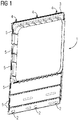
- a sidewall cladding element 1 is shown. This has for its own attachment to a shell of a rail vehicle according to the invention at its lower end three hooks 2 for hooking the side wall covering element 1 in a complementary configured to the hook guide, which in turn is attached to the shell of the rail vehicle, whereby the side wall covering element. 1 is attached to the shell of the rail vehicle.
- the guide as a hooked object forms, for example, as a rail parallel to the longitudinal axis of the rail vehicle, the counterpart to the hook 2, which is not shown here.
- the side wall cladding element 1 comprises a first profile rail 3, in which here three first holders 4 are guided.
- the first profile rail 3 serves for the free positioning of the first holder 4, which is complementary to the first profile rail 3, along the first profile rail 3 and for fastening the first holder 4 to the first profile rail 3.
- the first holders 4 are detachably connectable to the first profile rail 3. They are clamped, for example, with the first rail 3, wedged or screwed.
- they are connected to the shell of the rail vehicle, in particular detachable, connectable, for example by a screw connection.
- several sections of a first component of a two-part hook-and-loop fastener are additionally applied on the sidewall lining element 1, here in vertically extending strips 5. These likewise serve to fasten the sidewall lining element 1 to the shell of the rail vehicle.
- the sections of the other, second component of the hook and loop fastener which are arranged according to door and / or window columns.
- Fig. 2 illustrates in detail the attachment of a sidewall lining element 1 to a rail vehicle according to the invention.
- the side wall cladding element 1 has a hook 2 at its upper end.
- the hook 2 is hooked into a complementary configured to the hook 2 guide 10 of the rail vehicle.
- the hook 2 has a spur 9 which runs essentially parallel to the side wall cladding element 1. At its lower end, it has something away from the side wall cladding element 1 to easily hook the guide 10. Thus, it forms with the side wall cladding element 1 a wedge-shaped opening for receiving the guide 10.
- the hook 2 is here angularly curved, but may also be formed curved.
- the spur 9 of the hook 2 forms with the side wall cladding element 1 here a downwardly open fork for hooking the guide 10.
- the guide 10 is hooked between the side wall cladding element 1 and the spur 9 of the at least one hook 2 in the fork and by an elastic deformation of the Spurs 9 clamped.
- the guide 10 is here designed as a rail, which guides the side wall cladding element 1 in the longitudinal or direction of travel of the rail vehicle. It is located on the edge of a curved in the region of the side wall covering element 1 bottom 11.
- the bottom 11 is part of the shell of the rail vehicle or directly connected to this.
- the guide 10 for hooking the hook 2 for fastening the side wall lining element 1 on the shell of the rail vehicle is also part of the shell or directly connected to this.
- the bottom 11 forms here a simply curved shell. In other embodiments, it may also take the form of a double-curved shell. Is the Floor curved upwards on its front sides, it is designed trough-shaped.
- sealing lip 12 is mounted on the bottom 11. Alternatively, it is mounted on the sidewall covering element 1 and biased against the upwardly curved bottom 11 or the guide 10.
Description
- Die Erfindung betrifft ein Seitenwandverkleidungselement für ein Schienenfahrzeug und ein Schienenfahrzeug mit einem Seitenwandverkleidungselement.
- Bisher war es üblich, Seitenwandverkleidungselemente eines Schienenfahrzeugs mit dem Rohbau des Schienenfahrzeugs zu verschrauben. Ein Beispiel hierfür sind die Seitenwandverkleidungen des Combino der Siemens AG. Um die Seitenwandverkleidungselemente vandalismussicher mit dem Rohbau zu verbinden, ist eine Vielzahl an einzelnen Schraubverbindungen vorzusehen. Dies erfordert einen erheblichen Montage- und gegebenenfalls Demontageaufwand.
- Das dem Oberbegriff entsprechende Dokument
GB 03457 A (1912 DE 43 20 63 6 A1 undDE 44 45 250 A1 lehren die Befestigung von Innenverkleidungsteilen in Kraftfahrzeugen, die jeweils mit Haken zum Einhaken in Karosseriestrukturen versehen sind. - Der Erfindung liegt die Aufgabe zugrunde, eine montagefreundliche und vom Fahrgastraum eines Schienenfahrzeugs unsichtbare und vandalismussichere Seitenwandverkleidungsbefestiqunq vorzuschlagen.
- Gelöst wird die Aufgabe durch den Gegenstand des unabhängigen Patentanspruchs. Weiterbildungen und Ausgestaltungen der Erfindung finden sich in den Merkmalen der abhängigen Patentansprüche wieder.
- Ein erfindungsgemäßes Schienenfahrzeug, insbesondere ein Schienenfahrzeug des Personenverkehrs, umfasst ein Seitenwandverkleidungselement mit zumindest einem Haken und, zur Befestigung des Seitenwandverkleidunqselements an einem Rohbau des Schienenfahrzeugs, eine zu dem zumindest einen Haken des Seitenwandverkleidungselements komplementär ausgebildete Führung, welche Führung mit einem Rohbau des Schienenfahrzeugs verbunden ist, und welcher Haken und welche Führung zum Einhaken des Hakens des Seitenwandverkleidungselements in die Führung ausgestaltet sind. Der Haken des Seitenwandverkleidungselements ist erfindungsgemäß in die Führung eingehakt und somit ist das Seitenwandverkleidungselement mit dem Rohbau des Schienenfahrzeugs verbunden.
- Die Führung ist eine Schiene, so ist das Seitenwandverkleidungselement entlang der Schiene frei positionierbar. Sie verläuft insbesondere parallel zur Längsachse des Schienenfahrzeugs.
- Der Haken ist insbesondere derart ausgebildet, dass er zumindest senkrecht auf das Seitenwandverkleidungselement wirkt, so dass das Seitenwandverkleidungselement zumindest in dieser Richtung am Rohbau des Schienenfahrzeugs fixiert ist. Ist das Seitenwandverkleidungselement seinerseits vertikal im Schienenfahrzeug ausgerichtet, wirkt der Haken einem horizontalen Verschieben des Seitenwandverkleidungselements von der Führung weg entgegen.
- Weitergebildet weist der zumindest eine Haken des Seitenwandverkleidungselements einen Sporn auf, welcher zum Einhaken der Führung zwischen Sporn und Seitenwandverkleidungselement vom Seitenwandverkleidungselement beabstandet angeordnet ist.
- Gemäß einer Ausführungsform ist der Sporn des Hakens elastisch verformbar, insbesondere in eine Richtung senkrecht zum Seitenwandverkleidungselement. Dadurch ist die Führung zwischen Seitenwandverkleidungselement und Haken einklemmbar. Indem durch Einhaken der Führung der Sporn elastisch so verformt wird, dass der Abstand von dem Sporn zum Seitenwandverkleidungselement zunimmt, wirkt der Haken wie eine Feder, wodurch er gegen die Führung vorgespannt ist.
- Beispielsweise ist der zumindest eine Haken des Seitenwandverkleidungselements nach unten offen. Das Seitenwandverkleidungselement wird von oben in die Führung eingehakt und ist entsprechend im montierten Zustand in die Führung eingehängt. Damit ist der Haken so gegen die Richtung der Gewichtskraft des Seitenwandverkleidungselements in die Führung eingehakt, dass Selbstsperrung eintritt und somit ein Absinken des Seitenwandverkleidungselements blockiert ist.
- Gemäß einer weiteren Weiterbildung des Schienenfahrzeugs ist der zumindest eine Haken des Seitenwandverkleidungselements an einem unteren Ende des Seitenwandverkleidungselements angeordnet. Insbesondere sind zur eigenen Befestigung des Seitenwandverkleidungselements zumindest zwei oder mehrere Haken zum Einhaken und Befestigen des Seitenwandverkleidungselements in zumindest eine komplementär zu den Haken ausgestaltete Führung des Schienenfahrzeugs am unteren Ende des Seitenwandverkleidungselements angeordnet.
- Das Seitenwandverkleidungselement zur Verkleidung der Seitenwände im Innenraum, insbesondere im Fahrgastraum, des Schienenfahrzeugs erstreckt sich insbesondere zwischen dem Boden des Schienenfahrzeugs und einer Decke des Schienenfahrzeugs. Wie nachfolgend noch ausgeführt wird, kann es eine Höhe aufweisen, welche größer ist als der Abstand zwischen Decke und Boden des Innenraums des Schienenfahrzeugs.
- In einer weiteren Weiterbildung ist vorgesehen, dass das Seitenwandverkleidungselement zur eigenen Befestigung an dem Schienenfahrzeug zumindest eine erste Profilschiene zur freien Positionierung eines komplementär zur ersten Profilschiene ausgestalteten ersten Halters entlang der ersten Profilschiene und zur Befestigung des ersten Halters an der ersten Profilschiene umfasst. Der erste Halter ist zunächst frei entlang der ersten Profilschiene zu positionieren und anschließend an dieser Position mit der ersten Profilschiene zu verbinden, beispielsweise durch Anklemmen des ersten Halters an der ersten Profilschiene. Die Verbindung aus erster Profilschiene und erstem Halter ist dabei so ausgestaltet, dass sie geeignet ist, das Seitenwandverkleidungselement mit dem zumindest einen ersten Halter an einem Rohbau des Schienenfahrzeugs zu befestigen. Der erste Halter ist dann seinerseits mit dem Rohbau des Schienenfahrzeugs, insbesondere lösbar, verbunden, beispielsweise durch eine Schraubverbindung. Der erste Halter ist zunächst entlang der ersten Profilschiene des Seitenwandverkleidungselements frei positionierbar. Er wird insbesondere mit der Profilschiene verklemmt, verkeilt oder verschraubt und mit dem Rohbau des Schienenfahrzeugs ebenfalls lösbar verbunden, beispielsweise mittels einer Verschraubung.
- Der Rohbau weist eine begrenzte Anzahl an Positionen zur Anordnung von ersten Haltern auf. Durch die erste Profilschiene können Seitenwandverkleidungselemente jedoch unterschiedlich groß ausgeformt sein und/oder variabel längs der Längsachse des Schienenfahrzeugs angeordnet werden.
- Zur Befestigung von weiteren Verkleidungselementen, insbesondere Deckenverkleidungselementen, an dem Seitenwandverkleidungselement, kann es zumindest eine weitere, zweite Profilschiene zur freien Positionierung eines komplementär zur zweiten Profilschiene ausgestalteten, zweiten Halters entlang der zweiten Profilschiene und zur Befestigung des zweiten Halters an der frei ausgewählten Position der zweiten Profilschiene aufweisen.
- Das Seitenwandverkleidungselement umfasst sowohl die erste, als auch die zweite Profilschiene, wodurch die weiteren Verkleidungselemente am Seitenwandverkleidungselement und dadurch über das Seitenwandverkleidungselement am Rohbau des Schienenfahrzeugs befestigt sind.
- Die erste und/oder die zweite Profilschiene sind vorteilhaft parallel zur Längsachse des Schienenfahrzeugs angeordnet. Weitergebildet ist die erste und/oder die zweite Profilschiene im Querschnitt C-förmig ausgestaltet. Weist die erste C-förmig ausgestaltete Profilschiene eine vertikal ausgerichtete C-Öffnung auf und/oder weist die zweite C-förmig ausgestaltete Profilschiene eine horizontal ausgerichtete C-Öffnung auf, so weist die Öffnung der ersten Profilschiene insbesondere nach oben und/oder die Öffnung der zweiten Profilschiene weist zur Seite, insbesondere ins Innere des Schienenfahrzeugs, so dass der erste Halter von oben in die erste Profilschiene einführbar ist und insbesondere längs zur Längsachse des Schienenfahrzeugs in der ersten Profilschiene geführt ist und/oder der zweite Halter von oben in die zweite Profilschiene einführbar ist und insbesondere längs zur Längsachse des Schienenfahrzeugs in der zweiten Profilschiene geführt ist.
- Gemäß einer weiteren Ausgestaltung sind die erste und/oder die zweite Profilschiene am oberen Ende des Seitenwandverkleidungselements angeordnet.
- In vorteilhafter Weise sind die erste Profilschiene und die zweite Profilschiene stoffschlüssig miteinander verbunden, insbesondere fügestellenfrei. Monolithisch ausgebildet sind sie beispielsweise dadurch, dass sie aus einem Guss hergestellt sind, insbesondere sind sowohl die erste, als auch die zweite Profilschiene aus einem Strangpressprofil hergestellt.
- Ist lediglich ein einzelner Haken zum Einhaken in eine Führung vorgesehen, so ist auch dieser so dimensioniert, das Seitenwandverkleidungselement zusammen mit dem oder den Haltern am Rohbau des Schienenfahrzeugs zu befestigen. Sind mehrere Haken vorgesehen, so haltern sie das Seitenwandverkleidungselement gemeinschaftlich und können daher entsprechend ausgestaltet sein. Ist zusätzlich lediglich ein erster Halter zur Befestigung des Seitenwandverkleidungselements an einem Rohbau des Schienenfahrzeugs vorgesehen, so sind sowohl der einzelne, erste Halter, sowie die erste Profilschiene so dimensioniert, dass sie das Seitenwandverkleidungselement mit einer vorgegebenen Masse alleine haltern. Insbesondere sind jedoch zwei oder mehrere erste Halter zur Befestigung des Seitenwandverkleidungselements mit der ersten Profilschiene und dem Rohbau des Schienenfahrzeugs verbunden.
- Darüber hinaus kann das Seitenwandverkleidungselement zur eigenen Befestigung mit mehreren Abschnitten einer ersten Komponente eines aus zwei Komponenten bestehenden Klettverschlusses versehen sein, insbesondere in vertikal angeordneten Streifen, insbesondere an den Seiten oder Rändern des Seitenwandverkleidungselements, insbesondere entlang seiner Hochachse, senkrecht zur Längsachse des Schienenfahrzeugs. Abschnitte der anderen, zweiten Komponente des Klettverschlusses sind dann an dem Rohbau, beispielsweise an Türund/oder Fenstersäulen, entsprechend angeordnet. Die ersten Abschnitte der ersten Komponente des Klettverschlusses sind auf einer vom Innenraum, insbesondere Fahrgastraum, des Schienenfahrzeugs abgewandten Rückseite des Seitenwandverkleidungselements angeordnet. Die zweiten Abschnitte der zweiten Komponente des Klettverschlusses sind entsprechend auf einer in das Fahrzeuginnere weisenden Seite des Rohbaus angebracht.
- Wird das Seitenwandverkleidungselement bei der Montage in die untere Schiene einhakend eingeführt, kann es anschließend mit den Klettverschlüssen an dem Rohbau festgemacht werden, um es anschließend mit den ersten Haltern am Schienenfahrzeug zu befestigen.
- Eine Weiterbildung des erfindungsgemäßen Schienenfahrzeugs sieht vor, dass das Schienenfahrzeug einen Innenraum, insbesondere einen Fahrgastraum, mit einem Boden aufweist, welcher Boden im Bereich des Seitenwandverkleidungselements nach oben gekrümmt ist und an dessen Rand im Bereich der Seitenwand die Führung zum Einhaken des Hakens angeordnet ist. Der Boden erstreckt sich seitlich zumindest bis an die Seitenwände des Schienenfahrzeugs, welche zumindest teilweise von den Seitenwandverkleidungselementen gebildet werden. Insbesondere erstreckt sich der Boden bis jenseits der Seitenwandverkleidungselemente. Er ist seitlich hochgezogen. Seine seitlichen Ränder bilden somit nach oben weisende Abschlusskanten. Zumindest eine Führung zum Einhaken zumindest eines Seitenwandverkleidungselements ist an einem seitlichen Rand des Bodens angeordnet. Somit befindet sich der seitliche Rand des Bodens zwischen dem Rohbau des Schienenfahrzeugs und dem Seitenwandverkleidungselement, so dass der Sporn des Hakens auf der dem Innenraum gegenüberliegenden Seite des Bodens angeordnet ist, und insbesondere auf dieser Seite an der Führung anliegt. Wie oben bereits ausgeführt, ist die Führung vorteilhaft als Schiene zur freien Positionierung des Seitenwandverkleidungselements entlang der Führung ausgestaltet.
- Gemäß einer weiteren Weiterbildung umfasst das Schienenfahrzeug im Bereich der Seitenwand eine Dichtung, welche zwischen dem Boden und dem Seitenwandverkleidungselement angeordnet und dichtend gegen das Seitenwandverkleidungselement vorgespannt ist. Die Dichtlippe ist beispielsweise am Boden befestigt, kann jedoch auch direkt an der Führung angeordnet sein. Zusätzlich oder alternativ ist eine gleich wirkende Dichtung am Seitenwandverkleidungselement angeordnet. Die Dichtlippe weist insbesondere in das Innere des Schienenfahrzeugs.
- Die Erfindung lässt zahlreiche Ausführungsformen zu. Sie wird anhand der nachfolgenden Figuren näher erläutert, in denen jeweils ein Ausgestaltungsbeispiel dargestellt ist. Gleiche Elemente in den Figuren sind mit gleichen Bezugszeichen versehen.
- Fig. 1
- zeigt perspektivisch ein Seitenwandverkleidungselement von der zur Außenhaut eines erfindungsgemässen Schienenefahrzeugs weisenden Seite,
- Fig. 2
- zeigt einen Detailschnitt eines Befestigungsmechanismus des Seitenwandverkleidungselements.
- In
Fig. 1 ist ein Seitenwandverkleidungs-element 1 dargestellt. Dieses weist zur eigenen Befestigung an einem Rohbau eines erfindungsgemässen Schienenfahrzeugs an ihrem unteren Ende drei Haken 2 auf zum Einhaken des Seitenwandverkleidungselements 1 in eine komplementär zu den Haken ausgestaltete Führung, welche ihrerseits am Rohbau des Schienenfahrzeugs befestigt ist, wodurch auch das Seitenwandverkleidungselement 1 am Rohbau des Schienenfahrzeugs befestigt ist. Die Führung als einzuhakendes Objekt bildet, beispielsweise als Schiene parallel zur Längsachse des Schienenfahrzeugs ausgeführt, das Gegenstück zu den Haken 2, welches hier nicht näher dargestellt ist. - An ihrem oberen Ende umfasst das Seitenwandverkleidungselement 1 eine erste Profilschiene 3, in welcher hier drei erste Halter 4 geführt sind. Die erste Profilschiene 3 dient der freien Positionierung der komplementär zur ersten Profilschiene 3 ausgestalteten ersten Halter 4 entlang der ersten Profilschiene 3 und zur Befestigung der ersten Halter 4 an der ersten Profilschiene 3. Die ersten Halter 4 sind mit der ersten Profilschiene 3 lösbar verbindbar ausgestaltet. Sie werden beispielsweise mit der ersten Profilschiene 3 verklemmt, verkeilt oder verschraubt. Zusätzlich sind sie mit dem Rohbau des Schienenfahrzeugs, insbesondere lösbar, verbindbar, beispielsweise durch eine Schraubverbindung. Seitlich sind zusätzlich mehrere Abschnitte einer ersten Komponente eines aus zwei Komponenten bestehenden Klettverschlusses an dem Seitenwandverkleidungselement 1 appliziert, hier in vertikal verlaufenden Streifen 5. Diese dienen ebenfalls der Befestigung des Seitenwandverkleidungselements 1 am Rohbau des Schienenfahrzeugs. Hier nicht gezeigt sind die Abschnitte der anderen, zweiten Komponente des Klettverschlusses, welche an Tür- und/oder Fenstersäulen entsprechend angeordnet sind.
- Wird das hier skizzierte Seitenwandverkleidungselement 1 montiert, werden zunächst die Haken 2 in die Führung eingehakt und das Seitenwandverkleidungselement 1 ausgerichtet. Mittels Klettverschlüssen 5 erfolgt eine erste Fixierung. Anschließend werden die ersten Halter 4 in der ersten Profilschiene 3 mit dem Rohbau, insbesondere lösbar mittels Verschraubungen, verbunden. Ist eine doppelt wirkende oder eine zweite Profilschiene 6 vorgesehen, können anschließend noch Deckenelemente mit zweiten Haltern an dieser ausgerichtet und mit dieser verbunden werden, wodurch diese über das Seitenwandverkleidungselement 1 mit dem Rohbau des Schienenfahrzeugs verbunden sind.
-
Fig. 2 veranschaulicht detailliert die Befestigung eines Seitenwandverkleidungselements 1 an einem erfindungsgemässen Schienenfahrzeug. Das Seitenwandverkleidungselement 1 weist an seinem oberen Ende einen Haken 2 auf. Der Haken 2 ist in eine komplementär zum Haken 2 ausgestaltete Führung 10 des Schienenfahrzeugs eingehakt. - Der Haken 2 weist dazu einen Sporn 9 auf, welcher im Wesentlichen parallel zum Seitenwandverkleidungselement 1 verläuft. An seinem unteren Ende weist er etwas vom Seitenwandverkleidungselement 1 weg, um die Führung 10 leicht einzuhaken. Somit bildet er mit dem Seitenwandverkleidungselement 1 eine keilförmige Öffnung zur Aufnahme der Führung 10. Der Haken 2 ist hier eckig gekrümmt, kann jedoch auch geschwungen ausgeformt sein. Der Sporn 9 des Hakens 2 bildet mit dem Seitenwandverkleidungselement 1 eine hier nach unten offene Gabel zum Einhaken der Führung 10. Die Führung 10 ist zwischen dem Seitenwandverkleidungselement 1 und dem Sporn 9 des zumindest einen Hakens 2 in die Gabel eingehakt und durch eine elastische Verformung des Sporns 9 festgeklemmt.
- Die Führung 10 ist hier als Schiene ausgebildet, welche das Seitenwandverkleidungselement 1 in Längs- oder Fahrtrichtung des Schienenfahrzeugs führt. Sie befindet sich am Rand eines im Bereich des Seitenwandverkleidungselements 1 nach oben gekrümmten Bodens 11. Der Boden 11 ist dabei Teil des Rohbaus des Schienenfahrzeugs oder unmittelbar mit diesem verbunden. Dadurch ist die Führung 10 zum Einhaken des Hakens 2 zur Befestigung des Seitenwandverkleidungselements 1 am Rohbau des Schienenfahrzeugs ebenfalls Teil des Rohbaus oder direkt mit diesem verbunden. Der Boden 11 bildet hier eine einfach gekrümmte Schale. In weiteren Ausführungsformen kann er auch die Form einer doppelt gekrümmten Schale annehmen. Ist der Boden auch an seinen Stirnseiten nach oben gekrümmt, ist er wannenförmig ausgestaltet.
- Zwischen der Führung 10 und damit zwischen dem hochgezogenen und mit seinen seitlichen Rändern nach oben weisenden Boden 11 und dem Seitenwandverkleidungselement 1 ist eine nach innen in das Fahrzeuginnere weisende Dichtlippe 12 angeordnet. Diese ist im hier gezeigten, montierten Zustand gegen das Seitenwandverkleidungselement 1 vorgespannt, zur Abdichtung von Seitenwandverkleidungselement 1 und Boden 11. Die Dichtlippe 12 ist am Boden 11 montiert. Alternativ ist sie am Seitenwandverkleidungselement 1 montiert und gegen den nach oben gekrümmten Boden 11 oder die Führung 10 vorgespannt.
Claims (9)
- Schienenfahrzeug mit zumindest einem Seitenwandverkleidungselement (1), wobei das Seitenwandverkleidungselement (1) zur eigenen Befestigung zumindest einen Haken (2) zum Einhaken des Seitenwandverkleidungselements (1) in eine Führung (10) aufweist, welche Führung (10) mit einem Rohbau des Schienenfahrzeugs verbunden ist, dadurch gekennzeichnet, dass die Führung (10) als Schiene zur freien Positionierung des Seitenwandverkleidungselements (1) entlang der Führung (10) ausgestaltet ist.
- Schienenfahrzeug nach Anspruch 1, dadurch gekennzeichnet, dass der zumindest eine Haken (2) einen Sporn (9) aufweist, welcher zum Einhaken der Führung (10) zwischen Sporn (9) und Seitenwandverkleidungselement (1) vom Seitenwandverkleidungselement (1) beabstandet angeordnet ist.
- Schienenfahrzeug nach einem der Ansprüche 1 oder 2, dadurch gekennzeichnet, dass der zumindest eine Haken (2) an einem unteren Ende des Seitenwandverkleidungselements (1) angeordnet ist.
- Schienenfahrzeug nach einem der Ansprüche 1 bis 3, dadurch gekennzeichnet, dass der zumindest eine Haken (2) nach unten offen ist.
- Schienenfahrzeug nach einem der Ansprüche 1 bis 4, dadurch gekennzeichnet, dass das Seitenwandverkleidungselement (1) zur eigenen Befestigung erste Abschnitte eines Klettverschlusses (5) aufweist, und, dass zweite Abschnitte des Klettverschlusses mit dem Rohbau des Schienenfahrzeugs verbunden sind, welche erste und zweite Abschnitte miteinander verbindbar sind.
- Schienenfahrzeug nach einem der Ansprüche 1 bis 5, dadurch gekennzeichnet, dass es einen Innenraum mit einem Boden (11) aufweist, welcher im Bereich des Seitenwandverkleidungselements (1) nach oben gekrümmt ist und an dessen Rand im Bereich des Seitenwandverkleidungselements (1) die Führung (10) zum Einhaken des Hakens (2) angeordnet ist.
- Schienenfahrzeug nach Anspruch 6, dadurch gekennzeichnet, dass der Boden (11) im Bereich des Seitenwandverkleidungselements eine Dichtung (12) umfasst, welche zwischen dem Boden (11) und dem Seitenwandverkleidungselement (1) angeordnet und dichtend gegen das Seitenwandverkleidungselement (1) vorgespannt ist.
- Schienenfahrzeug nach einem der Ansprüche 1 bis 7, dadurch gekennzeichnet, dass das Seitenwandverkleidungselement (1) zur eigenen Befestigung eine erste Profilschiene (3) zur freien Positionierung eines komplementär zur ersten Profilschiene (3) ausgestalteten ersten Halters (4) entlang der ersten Profilschiene (3) und zur Befestigung des ersten Halters (4) am Seitenwandverkleidungselement (1) aufweist, wobei der erste Halter (4) mit einem Rohbau des Schienenfahrzeugs verbunden ist.
- Schienenfahrzeug nach Anspruch 8, dadurch gekennzeichnet, dass die erste Profilschiene (3) an einem oberen Ende des Seitenwandverkleidungselements (1) angeordnet ist.
Priority Applications (1)
| Application Number | Priority Date | Filing Date | Title |
|---|---|---|---|
| PL14707735T PL2945827T3 (pl) | 2013-03-28 | 2014-02-28 | Urządzenie montażowe do elementu okładziny ściany bocznej pojazdu szynowego |
Applications Claiming Priority (2)
| Application Number | Priority Date | Filing Date | Title |
|---|---|---|---|
| DE102013205608.7A DE102013205608A1 (de) | 2013-03-28 | 2013-03-28 | Montagevorrichtung für ein Seitenwandverkleidungselement eines Schienenfahrzeugs |
| PCT/EP2014/053928 WO2014154440A1 (de) | 2013-03-28 | 2014-02-28 | Montagevorrichtung für ein seitenwandverkleidungselement eines schienenfahrzeugs |
Publications (2)
| Publication Number | Publication Date |
|---|---|
| EP2945827A1 EP2945827A1 (de) | 2015-11-25 |
| EP2945827B1 true EP2945827B1 (de) | 2016-12-28 |
Family
ID=50193480
Family Applications (1)
| Application Number | Title | Priority Date | Filing Date |
|---|---|---|---|
| EP14707735.8A Active EP2945827B1 (de) | 2013-03-28 | 2014-02-28 | Montagevorrichtung für ein seitenwandverkleidungselement eines schienenfahrzeugs |
Country Status (8)
| Country | Link |
|---|---|
| US (1) | US9908537B2 (de) |
| EP (1) | EP2945827B1 (de) |
| CN (1) | CN205220674U (de) |
| DE (1) | DE102013205608A1 (de) |
| DK (1) | DK2945827T3 (de) |
| ES (1) | ES2621329T3 (de) |
| PL (1) | PL2945827T3 (de) |
| WO (1) | WO2014154440A1 (de) |
Families Citing this family (1)
| Publication number | Priority date | Publication date | Assignee | Title |
|---|---|---|---|---|
| US10467056B2 (en) * | 2017-05-12 | 2019-11-05 | Google Llc | Configuration of application software on multi-core image processor |
Family Cites Families (6)
| Publication number | Priority date | Publication date | Assignee | Title |
|---|---|---|---|---|
| GB191203547A (en) * | 1911-02-11 | 1913-02-12 | Alexandre Meyer | Covering for Railway Carriages and other Vehicles consisting of Decorated Vitrified or Enamelled Sheet Metal, Previously Prepared in the Factory for this Purpose. |
| DE1884477U (de) * | 1963-10-04 | 1963-12-12 | Rego Moebelwerk Otto Reitemeie | Befestigungsvorrichtung fuer wandverkleidungen. |
| DE4320636C2 (de) * | 1993-06-22 | 1999-12-02 | Magna Interior Systems Gmbh | Verkleidungsteil |
| DE4445250A1 (de) | 1994-12-19 | 1996-02-22 | Daimler Benz Ag | Dachverkleidungsplatte in einem Fahrzeuginnenraum |
| DE19616442A1 (de) * | 1996-04-25 | 1997-10-30 | Man Nutzfahrzeuge Ag | Lösbare Befestigung von Verkleidungsteilen im Innenraum von Kraftfahrzeugen |
| DE102007024804A1 (de) * | 2007-05-26 | 2008-11-27 | Aksys Gmbh | Selbsttragendes Karosserie-Struktur-Verbundbauteil-Modul |
-
2013
- 2013-03-28 DE DE102013205608.7A patent/DE102013205608A1/de not_active Ceased
-
2014
- 2014-02-28 ES ES14707735.8T patent/ES2621329T3/es active Active
- 2014-02-28 WO PCT/EP2014/053928 patent/WO2014154440A1/de active Application Filing
- 2014-02-28 DK DK14707735.8T patent/DK2945827T3/en active
- 2014-02-28 PL PL14707735T patent/PL2945827T3/pl unknown
- 2014-02-28 CN CN201490000536.7U patent/CN205220674U/zh not_active Expired - Lifetime
- 2014-02-28 US US14/780,621 patent/US9908537B2/en not_active Expired - Fee Related
- 2014-02-28 EP EP14707735.8A patent/EP2945827B1/de active Active
Also Published As
| Publication number | Publication date |
|---|---|
| DE102013205608A1 (de) | 2014-10-02 |
| CN205220674U (zh) | 2016-05-11 |
| ES2621329T3 (es) | 2017-07-03 |
| DK2945827T3 (en) | 2017-03-27 |
| WO2014154440A1 (de) | 2014-10-02 |
| US20160031455A1 (en) | 2016-02-04 |
| EP2945827A1 (de) | 2015-11-25 |
| PL2945827T3 (pl) | 2017-07-31 |
| US9908537B2 (en) | 2018-03-06 |
Similar Documents
| Publication | Publication Date | Title |
|---|---|---|
| EP2531383B1 (de) | Gurtaufrollerrahmen | |
| EP2508407B1 (de) | Gerüst, insbesondere für elektrische Einrichtungen in einem Schienenfahrzeug, und Verfahren zur Herstellung des Gerüsts | |
| EP2977298B1 (de) | Frontendmodul | |
| DE102013217399A1 (de) | Verkleidungsbefestigungssystem mit hoher haltekraft | |
| EP2945828B1 (de) | Montagevorrichtung für ein seitenwandverkleidungselement eines schienenfahrzeugs | |
| DE102008059990A1 (de) | Sonnendachmontagebaugruppe | |
| EP2945827B1 (de) | Montagevorrichtung für ein seitenwandverkleidungselement eines schienenfahrzeugs | |
| DE102008020051A1 (de) | Crashbox für eine Karosserie eines Kraftwagens | |
| DE102013205995A1 (de) | Befestigungsanordnung für ein Innenausstattungselement am Wagenkasten eines Fahrzeugs | |
| DE102016117057A1 (de) | Türrahmen eines Kraftfahrzeugs | |
| DE102015217463A1 (de) | Halter zur Befestigung an einem Strukturteil eines Kraftfahrzeuges sowie Anordnung eines Halters an einem Strukturteil eines Kraftfahrzeuges | |
| EP3424802A1 (de) | Reisemobil | |
| DE102015202420B4 (de) | Türinnenverkleidung, Fahrzeugtür mit einer Türinnenverkleidung sowie Fahrzeug mit einer Fahrzeugtür | |
| DE102012207446A1 (de) | Cantilever-Sitzträger | |
| DE102012023470A1 (de) | Anordnung zur Lagerung eines Ladebodens und Fahrzeug mit einer derartigen Anordnung | |
| DE102016004768B4 (de) | Befestigungsvorrichtung, die primär für die sichere Installation von Komponenten in einem Fahrzeug vorgesehen ist | |
| DE102014104435A1 (de) | Gurtumlenkungskonsole und Karosseriestruktur | |
| EP2383150B1 (de) | Befestigungsmittel im Fahrzeugkofferraum | |
| DE602005005559T2 (de) | Klammer für die Befestigung einer Schraube an Teile eines Automobils | |
| DE10055664B4 (de) | Dachanordnung für ein Fahrzeug | |
| DE202015104619U1 (de) | Ergänzender Stützflansch für eine Fahrzeugrahmensäule und erweiterte verglaste Öffung eines Panoramasonnendaches | |
| DE202013103414U1 (de) | Dachträger für ein Kraftfahrzeug | |
| DE102014007165A1 (de) | Sitzquerträger für eine Personenkraftwagenkarosserie | |
| DE102014006308A1 (de) | Haltevorrichtung zum Halten einer Sitzanlage eines Fahrzeugs | |
| DE102021110034A1 (de) | Optisch ansprechende Verkleidungsteilbefestigung |
Legal Events
| Date | Code | Title | Description |
|---|---|---|---|
| PUAI | Public reference made under article 153(3) epc to a published international application that has entered the european phase |
Free format text: ORIGINAL CODE: 0009012 |
|
| 17P | Request for examination filed |
Effective date: 20150821 |
|
| AK | Designated contracting states |
Kind code of ref document: A1 Designated state(s): AL AT BE BG CH CY CZ DE DK EE ES FI FR GB GR HR HU IE IS IT LI LT LU LV MC MK MT NL NO PL PT RO RS SE SI SK SM TR |
|
| AX | Request for extension of the european patent |
Extension state: BA ME |
|
| REG | Reference to a national code |
Ref country code: DE Ref legal event code: R079 Ref document number: 502014002337 Country of ref document: DE Free format text: PREVIOUS MAIN CLASS: B61D0017180000 Ipc: B61D0001000000 |
|
| DAX | Request for extension of the european patent (deleted) | ||
| RIC1 | Information provided on ipc code assigned before grant |
Ipc: B61D 17/18 20060101ALI20160623BHEP Ipc: B61D 17/00 20060101ALI20160623BHEP Ipc: B61D 1/00 20060101AFI20160623BHEP |
|
| GRAP | Despatch of communication of intention to grant a patent |
Free format text: ORIGINAL CODE: EPIDOSNIGR1 |
|
| INTG | Intention to grant announced |
Effective date: 20160801 |
|
| GRAS | Grant fee paid |
Free format text: ORIGINAL CODE: EPIDOSNIGR3 |
|
| GRAA | (expected) grant |
Free format text: ORIGINAL CODE: 0009210 |
|
| AK | Designated contracting states |
Kind code of ref document: B1 Designated state(s): AL AT BE BG CH CY CZ DE DK EE ES FI FR GB GR HR HU IE IS IT LI LT LU LV MC MK MT NL NO PL PT RO RS SE SI SK SM TR |
|
| REG | Reference to a national code |
Ref country code: GB Ref legal event code: FG4D Free format text: NOT ENGLISH |
|
| REG | Reference to a national code |
Ref country code: CH Ref legal event code: EP |
|
| REG | Reference to a national code |
Ref country code: AT Ref legal event code: REF Ref document number: 856985 Country of ref document: AT Kind code of ref document: T Effective date: 20170115 |
|
| REG | Reference to a national code |
Ref country code: IE Ref legal event code: FG4D Free format text: LANGUAGE OF EP DOCUMENT: GERMAN |
|
| REG | Reference to a national code |
Ref country code: CH Ref legal event code: NV Representative=s name: SIEMENS SCHWEIZ AG, CH |
|
| REG | Reference to a national code |
Ref country code: DE Ref legal event code: R096 Ref document number: 502014002337 Country of ref document: DE |
|
| REG | Reference to a national code |
Ref country code: FR Ref legal event code: PLFP Year of fee payment: 4 |
|
| PG25 | Lapsed in a contracting state [announced via postgrant information from national office to epo] |
Ref country code: LV Free format text: LAPSE BECAUSE OF FAILURE TO SUBMIT A TRANSLATION OF THE DESCRIPTION OR TO PAY THE FEE WITHIN THE PRESCRIBED TIME-LIMIT Effective date: 20161228 |
|
| REG | Reference to a national code |
Ref country code: DK Ref legal event code: T3 Effective date: 20170321 |
|
| REG | Reference to a national code |
Ref country code: NL Ref legal event code: FP |
|
| REG | Reference to a national code |
Ref country code: LT Ref legal event code: MG4D |
|
| PG25 | Lapsed in a contracting state [announced via postgrant information from national office to epo] |
Ref country code: GR Free format text: LAPSE BECAUSE OF FAILURE TO SUBMIT A TRANSLATION OF THE DESCRIPTION OR TO PAY THE FEE WITHIN THE PRESCRIBED TIME-LIMIT Effective date: 20170329 Ref country code: SE Free format text: LAPSE BECAUSE OF FAILURE TO SUBMIT A TRANSLATION OF THE DESCRIPTION OR TO PAY THE FEE WITHIN THE PRESCRIBED TIME-LIMIT Effective date: 20161228 Ref country code: NO Free format text: LAPSE BECAUSE OF FAILURE TO SUBMIT A TRANSLATION OF THE DESCRIPTION OR TO PAY THE FEE WITHIN THE PRESCRIBED TIME-LIMIT Effective date: 20170328 Ref country code: LT Free format text: LAPSE BECAUSE OF FAILURE TO SUBMIT A TRANSLATION OF THE DESCRIPTION OR TO PAY THE FEE WITHIN THE PRESCRIBED TIME-LIMIT Effective date: 20161228 |
|
| PG25 | Lapsed in a contracting state [announced via postgrant information from national office to epo] |
Ref country code: FI Free format text: LAPSE BECAUSE OF FAILURE TO SUBMIT A TRANSLATION OF THE DESCRIPTION OR TO PAY THE FEE WITHIN THE PRESCRIBED TIME-LIMIT Effective date: 20161228 Ref country code: HR Free format text: LAPSE BECAUSE OF FAILURE TO SUBMIT A TRANSLATION OF THE DESCRIPTION OR TO PAY THE FEE WITHIN THE PRESCRIBED TIME-LIMIT Effective date: 20161228 Ref country code: RS Free format text: LAPSE BECAUSE OF FAILURE TO SUBMIT A TRANSLATION OF THE DESCRIPTION OR TO PAY THE FEE WITHIN THE PRESCRIBED TIME-LIMIT Effective date: 20161228 |
|
| REG | Reference to a national code |
Ref country code: ES Ref legal event code: FG2A Ref document number: 2621329 Country of ref document: ES Kind code of ref document: T3 Effective date: 20170703 |
|
| PG25 | Lapsed in a contracting state [announced via postgrant information from national office to epo] |
Ref country code: RO Free format text: LAPSE BECAUSE OF FAILURE TO SUBMIT A TRANSLATION OF THE DESCRIPTION OR TO PAY THE FEE WITHIN THE PRESCRIBED TIME-LIMIT Effective date: 20161228 Ref country code: EE Free format text: LAPSE BECAUSE OF FAILURE TO SUBMIT A TRANSLATION OF THE DESCRIPTION OR TO PAY THE FEE WITHIN THE PRESCRIBED TIME-LIMIT Effective date: 20161228 Ref country code: SK Free format text: LAPSE BECAUSE OF FAILURE TO SUBMIT A TRANSLATION OF THE DESCRIPTION OR TO PAY THE FEE WITHIN THE PRESCRIBED TIME-LIMIT Effective date: 20161228 Ref country code: IS Free format text: LAPSE BECAUSE OF FAILURE TO SUBMIT A TRANSLATION OF THE DESCRIPTION OR TO PAY THE FEE WITHIN THE PRESCRIBED TIME-LIMIT Effective date: 20170428 |
|
| RAP2 | Party data changed (patent owner data changed or rights of a patent transferred) |
Owner name: SIEMENS AKTIENGESELLSCHAFT |
|
| PG25 | Lapsed in a contracting state [announced via postgrant information from national office to epo] |
Ref country code: BG Free format text: LAPSE BECAUSE OF FAILURE TO SUBMIT A TRANSLATION OF THE DESCRIPTION OR TO PAY THE FEE WITHIN THE PRESCRIBED TIME-LIMIT Effective date: 20170328 Ref country code: SM Free format text: LAPSE BECAUSE OF FAILURE TO SUBMIT A TRANSLATION OF THE DESCRIPTION OR TO PAY THE FEE WITHIN THE PRESCRIBED TIME-LIMIT Effective date: 20161228 Ref country code: PT Free format text: LAPSE BECAUSE OF FAILURE TO SUBMIT A TRANSLATION OF THE DESCRIPTION OR TO PAY THE FEE WITHIN THE PRESCRIBED TIME-LIMIT Effective date: 20170428 |
|
| PG25 | Lapsed in a contracting state [announced via postgrant information from national office to epo] |
Ref country code: MC Free format text: LAPSE BECAUSE OF FAILURE TO SUBMIT A TRANSLATION OF THE DESCRIPTION OR TO PAY THE FEE WITHIN THE PRESCRIBED TIME-LIMIT Effective date: 20161228 |
|
| REG | Reference to a national code |
Ref country code: CH Ref legal event code: PCOW Free format text: NEW ADDRESS: WERNER-VON-SIEMENS-STRASSE 1, 80333 MUENCHEN (DE) Ref country code: DE Ref legal event code: R097 Ref document number: 502014002337 Country of ref document: DE |
|
| PLBE | No opposition filed within time limit |
Free format text: ORIGINAL CODE: 0009261 |
|
| STAA | Information on the status of an ep patent application or granted ep patent |
Free format text: STATUS: NO OPPOSITION FILED WITHIN TIME LIMIT |
|
| REG | Reference to a national code |
Ref country code: IE Ref legal event code: MM4A |
|
| 26N | No opposition filed |
Effective date: 20170929 |
|
| PG25 | Lapsed in a contracting state [announced via postgrant information from national office to epo] |
Ref country code: LU Free format text: LAPSE BECAUSE OF NON-PAYMENT OF DUE FEES Effective date: 20170228 |
|
| REG | Reference to a national code |
Ref country code: FR Ref legal event code: PLFP Year of fee payment: 5 |
|
| PG25 | Lapsed in a contracting state [announced via postgrant information from national office to epo] |
Ref country code: IE Free format text: LAPSE BECAUSE OF NON-PAYMENT OF DUE FEES Effective date: 20170228 Ref country code: SI Free format text: LAPSE BECAUSE OF FAILURE TO SUBMIT A TRANSLATION OF THE DESCRIPTION OR TO PAY THE FEE WITHIN THE PRESCRIBED TIME-LIMIT Effective date: 20161228 |
|
| PG25 | Lapsed in a contracting state [announced via postgrant information from national office to epo] |
Ref country code: MT Free format text: LAPSE BECAUSE OF FAILURE TO SUBMIT A TRANSLATION OF THE DESCRIPTION OR TO PAY THE FEE WITHIN THE PRESCRIBED TIME-LIMIT Effective date: 20161228 |
|
| REG | Reference to a national code |
Ref country code: DE Ref legal event code: R081 Ref document number: 502014002337 Country of ref document: DE Owner name: SIEMENS MOBILITY GMBH, DE Free format text: FORMER OWNER: SIEMENS AKTIENGESELLSCHAFT, 80333 MUENCHEN, DE |
|
| REG | Reference to a national code |
Ref country code: CH Ref legal event code: PUE Owner name: SIEMENS MOBILITY GMBH, DE Free format text: FORMER OWNER: SIEMENS AKTIENGESELLSCHAFT, DE |
|
| REG | Reference to a national code |
Ref country code: GB Ref legal event code: 732E Free format text: REGISTERED BETWEEN 20190207 AND 20190213 |
|
| REG | Reference to a national code |
Ref country code: AT Ref legal event code: PC Ref document number: 856985 Country of ref document: AT Kind code of ref document: T Owner name: SIEMENS MOBILITY GMBH, DE Effective date: 20190506 |
|
| PG25 | Lapsed in a contracting state [announced via postgrant information from national office to epo] |
Ref country code: HU Free format text: LAPSE BECAUSE OF FAILURE TO SUBMIT A TRANSLATION OF THE DESCRIPTION OR TO PAY THE FEE WITHIN THE PRESCRIBED TIME-LIMIT; INVALID AB INITIO Effective date: 20140228 |
|
| REG | Reference to a national code |
Ref country code: NL Ref legal event code: PD Owner name: SIEMENS MOBILITY GMBH; DE Free format text: DETAILS ASSIGNMENT: CHANGE OF OWNER(S), ASSIGNMENT; FORMER OWNER NAME: SIEMENS AKTIENGESELLSCHAFT Effective date: 20190829 |
|
| PG25 | Lapsed in a contracting state [announced via postgrant information from national office to epo] |
Ref country code: CY Free format text: LAPSE BECAUSE OF FAILURE TO SUBMIT A TRANSLATION OF THE DESCRIPTION OR TO PAY THE FEE WITHIN THE PRESCRIBED TIME-LIMIT Effective date: 20161228 |
|
| PG25 | Lapsed in a contracting state [announced via postgrant information from national office to epo] |
Ref country code: MK Free format text: LAPSE BECAUSE OF FAILURE TO SUBMIT A TRANSLATION OF THE DESCRIPTION OR TO PAY THE FEE WITHIN THE PRESCRIBED TIME-LIMIT Effective date: 20161228 |
|
| REG | Reference to a national code |
Ref country code: BE Ref legal event code: PD Owner name: SIEMENS MOBILITY GMBH; DE Free format text: DETAILS ASSIGNMENT: CHANGE OF OWNER(S), CESSION; FORMER OWNER NAME: SIEMENS AKTIENGESELLSCHAFT Effective date: 20190911 |
|
| PG25 | Lapsed in a contracting state [announced via postgrant information from national office to epo] |
Ref country code: AL Free format text: LAPSE BECAUSE OF FAILURE TO SUBMIT A TRANSLATION OF THE DESCRIPTION OR TO PAY THE FEE WITHIN THE PRESCRIBED TIME-LIMIT Effective date: 20161228 |
|
| REG | Reference to a national code |
Ref country code: ES Ref legal event code: PC2A Owner name: SIEMENS MOBILITY GMBH Effective date: 20200805 |
|
| PGFP | Annual fee paid to national office [announced via postgrant information from national office to epo] |
Ref country code: ES Payment date: 20210524 Year of fee payment: 8 |
|
| PGFP | Annual fee paid to national office [announced via postgrant information from national office to epo] |
Ref country code: GB Payment date: 20220310 Year of fee payment: 9 |
|
| PGFP | Annual fee paid to national office [announced via postgrant information from national office to epo] |
Ref country code: FR Payment date: 20220223 Year of fee payment: 9 |
|
| PGFP | Annual fee paid to national office [announced via postgrant information from national office to epo] |
Ref country code: NL Payment date: 20230202 Year of fee payment: 10 |
|
| PGFP | Annual fee paid to national office [announced via postgrant information from national office to epo] |
Ref country code: DK Payment date: 20230220 Year of fee payment: 10 Ref country code: CZ Payment date: 20230220 Year of fee payment: 10 Ref country code: AT Payment date: 20230109 Year of fee payment: 10 |
|
| REG | Reference to a national code |
Ref country code: ES Ref legal event code: FD2A Effective date: 20230509 |
|
| PGFP | Annual fee paid to national office [announced via postgrant information from national office to epo] |
Ref country code: TR Payment date: 20230227 Year of fee payment: 10 Ref country code: PL Payment date: 20230217 Year of fee payment: 10 Ref country code: IT Payment date: 20230221 Year of fee payment: 10 Ref country code: BE Payment date: 20230216 Year of fee payment: 10 |
|
| PG25 | Lapsed in a contracting state [announced via postgrant information from national office to epo] |
Ref country code: ES Free format text: LAPSE BECAUSE OF NON-PAYMENT OF DUE FEES Effective date: 20220301 |
|
| PGFP | Annual fee paid to national office [announced via postgrant information from national office to epo] |
Ref country code: DE Payment date: 20230419 Year of fee payment: 10 Ref country code: CH Payment date: 20230504 Year of fee payment: 10 |
|
| GBPC | Gb: european patent ceased through non-payment of renewal fee |
Effective date: 20230228 |
|
| PG25 | Lapsed in a contracting state [announced via postgrant information from national office to epo] |
Ref country code: GB Free format text: LAPSE BECAUSE OF NON-PAYMENT OF DUE FEES Effective date: 20230228 |
|
| PG25 | Lapsed in a contracting state [announced via postgrant information from national office to epo] |
Ref country code: GB Free format text: LAPSE BECAUSE OF NON-PAYMENT OF DUE FEES Effective date: 20230228 Ref country code: FR Free format text: LAPSE BECAUSE OF NON-PAYMENT OF DUE FEES Effective date: 20230228 |
|
| PGFP | Annual fee paid to national office [announced via postgrant information from national office to epo] |
Ref country code: NL Payment date: 20240205 Year of fee payment: 11 |