EP3211130A1 - Filterdeckel, filtereinsatz und waschmaschine - Google Patents
Filterdeckel, filtereinsatz und waschmaschine Download PDFInfo
- Publication number
- EP3211130A1 EP3211130A1 EP17155435.5A EP17155435A EP3211130A1 EP 3211130 A1 EP3211130 A1 EP 3211130A1 EP 17155435 A EP17155435 A EP 17155435A EP 3211130 A1 EP3211130 A1 EP 3211130A1
- Authority
- EP
- European Patent Office
- Prior art keywords
- filter
- filter cover
- extension direction
- cover
- washing machine
- Prior art date
- Legal status (The legal status is an assumption and is not a legal conclusion. Google has not performed a legal analysis and makes no representation as to the accuracy of the status listed.)
- Granted
Links
Images


Classifications
-
- D—TEXTILES; PAPER
- D06—TREATMENT OF TEXTILES OR THE LIKE; LAUNDERING; FLEXIBLE MATERIALS NOT OTHERWISE PROVIDED FOR
- D06F—LAUNDERING, DRYING, IRONING, PRESSING OR FOLDING TEXTILE ARTICLES
- D06F39/00—Details of washing machines not specific to a single type of machines covered by groups D06F9/00 - D06F27/00
- D06F39/08—Liquid supply or discharge arrangements
- D06F39/083—Liquid discharge or recirculation arrangements
-
- D—TEXTILES; PAPER
- D06—TREATMENT OF TEXTILES OR THE LIKE; LAUNDERING; FLEXIBLE MATERIALS NOT OTHERWISE PROVIDED FOR
- D06F—LAUNDERING, DRYING, IRONING, PRESSING OR FOLDING TEXTILE ARTICLES
- D06F39/00—Details of washing machines not specific to a single type of machines covered by groups D06F9/00 - D06F27/00
- D06F39/10—Filtering arrangements
Definitions
- the invention relates to a filter cover, a filter cartridge and a washing machine.
- the invention relates to a filter cover and a filter insert, which can be arranged in an aggregate housing of a lye and / or Umwutpumpenaggregats the washing machine or are.
- the filter element has the filter cover and a filter body.
- the filter body has a screw cap to which a filter is connected via a center column.
- the filter cover is disposed on the filter.
- the filter cartridge is disposed in the sewage path of the washing machine to allow foreign bodies to be separated from wash liquor before the wash liquor flows through a pumping chamber of the leach and / or circulating pump assembly.
- the filter cover is used for fluidic separation of the unit housing in a filter chamber having the filter insert, and the pump chamber having a pump in particular a lye and / or Umflutpumpe.
- the filter cartridge To protect the pump from contamination and foreign matter damage, insert the filter cartridge into the filter chamber, which passes the wash liquor in front of the pump chamber when the pump is operating.
- buttons, curtains rolls, etc. can be deposited and / or foreign bodies such as threads and / or lint can be retained.
- the filter element is screwed to the unit housing by means of the screw cap, which is accessible from the outside of the washing machine.
- the filter insert seals the filter chamber in two places. Directly on the screw connection with the unit housing, the filter body prevents the escape of water from the washing machine.
- the filter cover closes off the pump chamber to avoid a "short circuit" in the water circuit.
- the filter cover is adapted to the filter body in particular one side of the filter cover to the filter.
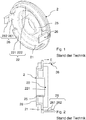
- Fig. 1 shows schematically a plan view of a filter cover according to the prior art.
- the filter cover 2 has an upper side (not shown) and a lower side 21, which can be arranged on a filter (not shown) of a filter body (not shown).
- the filter cover 2 has a suction nozzle 25 which extends from the bottom 21 in an extension direction (not shown) and is arranged centrally in a circular shape of the filter cover 2 in plan view of the bottom 21. From the underside 21 of the filter cover 2 further extends a wall member 22 in the extension direction (not shown).
- the Wall element 22 is segmented and, in particular, arranged annularly in an edge region of the filter cover 2.
- the wall element 22 has a segment 221 and a further segment 222, which are arranged at a distance from one another.
- a projection element 26 is arranged at a distance from them.
- the protruding member 26 has a wall portion 261 extending from the lower side 21 in the extending direction (not shown), and a protruding portion 262 disposed at an opposite end of the protrusion member 26 on a side of the wall portion facing the suction port 25 261 is formed.
- Fig. 2 schematically shows a sectional view of the in Fig. 1 shown filter cover.
- Fig. 2 shows a sectional view of a halved filter cover 2. It is shown the plan view of the half of the filter cover 2 with the segment 221 of the wall element 22.
- the filter cover 2 is attached to the filter (not shown) of the filter body (not shown) ) arranged.
- the underside 21 of the filter cover 2 faces a filter chamber (not shown) of the unit housing, while the top 28 of the filter cover 2 faces a pump chamber (not shown) of the unit housing.
- the segment 221 of the wall element 22 is arranged at a distance from the projection elements 26.
- the extension direction E is perpendicular or substantially perpendicular to the underside 21 of the filter cover 2.
- FIG. 1 and 2 shown filter cover 2 is formed, to be arranged together with the filter body (not shown) in the unit housing of the lye and / or Umwutpumpenaggregats, in Fig. 3 and 4 is shown.
- Fig. 3 shows schematically a plan view of a unit housing according to the prior art, which is part of the lye and / or Umwutpumpenaggregats the washing machine
- Fig. 4 schematically shows a cross-sectional view of the in Fig. 3 shown unit housing according to the prior art.
- the unit housing 3 has a filter chamber 31 and a pump chamber 32 (in Fig. 3 not apparent), which are caused by the in Fig. 1 and 2 shown filter cover (not shown) can be fluidly separated.
- a pump such as a lye and / or Umflutpumpe is arranged.
- a filter cartridge (not shown) is arranged, in addition to the in Fig. 1 and 2 shown filter cover (not shown) with a screw cap (not shown), to which via a center column (not shown), a filter (not shown) is connected.
- the screw cap can be screwed to a thread 35 of the unit housing 3, so that the center column and the filter extend into the filter chamber 31.
- the filter is positioned in the unit case 3 so as to be fixed to the underside of the in Fig. 1 and 2 arranged filter cover is arranged.
- an inlet nozzle 33 is arranged, and on the pump chamber 32 is a discharge nozzle 34 (not in Fig. 4 can be seen), which are connected to other lines (not shown) of the washing machine (not shown).
- the pump of the leaching and / or Umwutaggregats when the pump of the leaching and / or Umwutaggregats is activated to pump liquid such as water or wash liquor through the leaching and / or Umwutaggregat, the liquid flows through the inlet nozzle 33 into the filter chamber 31, passes through the filter body in particular the filter and is guided through the suction nozzle 25 into the pump chamber 32 and removed via the discharge nozzle 34 from the pump chamber 32.
- Tolerances between the filter body and the filter cover must be compensated to ensure a seal of the pump chamber with respect to the filter chamber. Furthermore, a seal must be ensured at the screw connection of the filter body to the unit housing. Tolerances of the components can be compensated to some extent when the filter cover and the filter body have elastic material. There is a need for a sealing of the pump chamber with respect to the filter chamber of the leaching and / or Umflutaggregats, without affecting the seal on the screw of the filter body with the unit housing of the washing machine.
- the invention thus presents the problem of providing a filter cover, a filter cartridge and a washing machine, in which the filter cover is designed to compensate for a tolerance between a filter body and the filter cover, as a filter insert in an aggregate housing a lye and / or Umwutpumpenaggregats the washing machine are arranged, wherein the filter cover for fluidic separation of two chambers, in particular a filter chamber in which the filter insert is arranged et, and a pump chamber is used, in which a pump is arranged.
- the filter cover for insertion into an aggregate housing of a lye and / or Umwutpumpenaggregats a washing machine has an upper side and a lower side.
- a central suction nozzle extends from the underside of the filter cover in an extension direction.
- a segmented wall element extends from the underside in the extension direction.
- the filter cover has a spring element.
- the extension direction is preferably perpendicular or substantially perpendicular to the underside of the filter cover.
- the filter cover preferably has a circular shape in plan view of the top or the bottom.
- the suction nozzle is formed centrally on the filter cover in this plan view.
- the segmented wall element preferably has two or possibly more segments, which are spaced from each other in an annular manner.
- the segments are preferably arranged annularly at an edge region of the underside.
- Each segment of the wall element preferably has one spring element or a plurality of spring elements.
- a projection element is arranged, which has a extending from the bottom in the direction of extension wall portion and a projection portion which at an opposite end of the underside of the projection element on a suction nozzle is formed facing side of the wall portion.
- the spring element has an opening arranged in the wall element and a projection which is arranged in the extension direction of the wall element.
- the projection preferably extends in the direction of extension.
- the combination of the opening and the projection is adapted to provide a suspension for the filter cover.
- the opening in the direction of extension of the wall element is arranged below the projection as seen from the underside.
- the projection is formed centrally or substantially centrally above the opening in the direction of extension of the wall element viewed from the underside.
- the protrusion preferably extends in the extension direction with a protrusion length equal to or smaller than a protrusion width extending perpendicularly or substantially perpendicular to the extension direction.
- the projection preferably has a projection length of 1.0 to 2.0 mm in the extension direction.
- the opening preferably has an opening length in the direction of extent which is substantially smaller than an opening width extending perpendicular to the extension direction.
- the opening length is, for example, ten times smaller than the opening width.
- the opening preferably has an opening length in the range of 1.5 to 2.5 mm in the direction of extension and an opening width in the range of 1.5 to 2.5 cm perpendicular to the direction of extent.
- a material of the filter cover is preferably plastic.
- a material of the filter cover is more preferably polypropylene.
- the filter cover is integrally formed.
- the invention further relates to a filter cartridge comprising a filter body and the filter cover in one or more of the above-described embodiments according to the invention.
- the filter body preferably has a screw cap to which a filter is connected via a center column.
- a material of the filter body is preferably plastic preferred glass fiber reinforced polypropylene.
- the filter is a sieve or labyrinth filter.
- the filter can act as a lint filter or heavy body trap.
- the use of the low-maintenance labyrinth filter usually meets the requirements of most washing machine users, since the proportion of lint, threads and the like. In the wash liquor is usually low and does not significantly affect the function of the pump or subsequent piping.
- One or more seals may be formed and / or arranged on the filter body. As a result, tolerances between the components can be compensated.
- the invention further relates to a washing machine having an aggregate housing and a filter cover in one or more of the embodiments described above according to the invention or a filter cartridge in one or more of the embodiments described above according to the invention.
- the unit housing is preferably part of a lye and / or Umwutpumpenaggregats.
- the unit housing preferably has a filter chamber for receiving the filter cartridge and a pump chamber for receiving a pump, which are fluidly separated by the filter cover.
- a pump such as a lye and / or Umflutpumpe is arranged in the filter chamber.
- the above filter insert is arranged.
- the screw cap of the filter body is screwed to a thread of the unit housing, so that the center column and the filter of the filter body extend into the filter chamber, wherein the filter is positioned in the unit housing so that it is arranged on the underside of the filter cover.
- washing machine is in addition to a device that is designed for washing laundry, a combination device as a washer-dryer to understand.
- the washing machine may be a household appliance or a commercially used appliance.
- the washing machine is a washer-dryer.
- Fig. 1 to 4 which constitute the filter cover or the aggregate housing according to the prior art, are already described above.
- Fig. 5 schematically shows a plan view of a filter cover according to the invention.
- the in Fig. 5 shown filter cover 2 corresponds to the in Fig. 1 and 2 shown filter cover 2 with the difference that it comprises a spring element having an opening arranged in the wall member 22 24 and a projection 23 which is arranged in the extension direction (not shown) of the wall element 22.
- the two segments 221, 222 of the wall member 22 each have two spring elements, each having an opening 24 and a projection 23.
- the segment 221 and the further segment 222 each have a segment projection 27 which is arranged between the two openings 24 of each segment 221, 222 on a side facing away from the suction nozzle 25 of the wall element 22.
- Fig. 6 schematically shows a sectional view of the in Fig. 5 shown filter cover.
- Fig. 6 shows a sectional view of the halved filter cover 2. It is shown the plan view of the half of the filter cover 2 with the segment 221 of the wall element 22.
- the segment 221 of the wall element 22 has two spring elements, each having an opening 24 and a projection 23. Each opening 24 is in the direction of extension E of the wall element 22 seen from the bottom 21 from each below the projection 23 associated therewith.
- the protrusions 23 of the segment 221 each extend in the extension direction E with a protrusion length equal to or smaller than a protrusion width extending perpendicularly or substantially perpendicular to the extension direction E.
- the openings 24 of the segment 221 have an opening length in the extension direction E which is substantially smaller than a vertical one extending to the extension direction E opening width.
- the opening length is, for example, ten times smaller than the opening width, for example in the millimeter range, while the opening width is in the centimeter range.
- Fig. 7 schematically shows a further sectional view of the in Fig. 5 shown filter cover. It is shown a further sectional view of another halved filter cover 2.
- a segment projection 27 is arranged in each case on the segment 221 and the further segment 222 perpendicularly or substantially perpendicular to the extension direction E on the side of the segmented wall element 22 facing away from the suction port 25.
Landscapes
- Engineering & Computer Science (AREA)
- Textile Engineering (AREA)
- Detail Structures Of Washing Machines And Dryers (AREA)
Abstract
Description
- Die Erfindung betrifft einen Filterdeckel, einen Filtereinsatz und eine Waschmaschine. Insbesondere betrifft die Erfindung einen Filterdeckel und einen Filtereinsatz, die in ein Aggregatgehäuse eines Laugen- und/oder Umflutpumpenaggregats der Waschmaschine angeordnet werden können bzw. sind.
- Der Filtereinsatz weist den Filterdeckel und einen Filterkörper auf. Der Filterkörper weist einen Schraubdeckel auf, an den über eine Mittelsäule ein Filter angeschlossen ist. Wenn der Filtereinsatz in dem Aggregatgehäuse angeordnet ist, ist der Filterdeckel an dem Filter angeordnet. Der Filtereinsatz ist im Abwasserweg der Waschmaschine angeordnet, um ein Abscheiden von Fremdkörpern aus Waschlauge zu ermöglichen, bevor die Waschlauge durch eine Pumpenkammer des Laugen- und/oder Umflutpumpenaggregats strömt. Der Filterdeckel dient zur strömungstechnischen Trennung des Aggregatgehäuses in eine Filterkammer, die den Filtereinsatz aufweist, und die Pumpenkammer, die eine Pumpe insbesondere eine Laugen- und/oder Umflutpumpe aufweist.
- Um die Pumpe vor Verunreinigung und Beschädigung durch Fremdkörper zu schützen, wird der Filtereinsatz in die Filterkammer eingesetzt, die die Waschlauge bei Betrieb der Pumpe vor der Pumpenkammer passiert. Je nach Auslegung des Filtereinsatzes können Knöpfe, Gardinenrollen etc. abgeschieden werden und/oder können Fremdkörper wie Fäden und/oder Flusen zurückgehalten werden. Der Filtereinsatz ist mit dem Aggregatgehäuse mittels des Schraubdeckels verschraubt, der von der Außenseite der Waschmaschine zugänglich ist. Der Filtereinsatz dichtet die Filterkammer an zwei Stellen ab. Direkt an der Verschraubung mit dem Aggregatgehäuse verhindert der Filterkörper das Austreten von Wasser aus der Waschmaschine. Im Aggregatgehäuse schließt der Filterdeckel die Pumpenkammer ab, um einen "Kurzschluss" im Wasserkreislauf zu vermeiden. Dazu ist es notwendig, dass der Filterdeckel an den Filterkörper insbesondere eine Seite des Filterdeckels an das Filter angepasst ist.
-
Fig. 1 zeigt schematisch eine Draufsicht auf einen Filterdeckel nach dem Stand der Technik. Der Filterdeckel 2 weist eine Oberseite (nicht gezeigt) und eine Unterseite 21 auf, die an einem Filter (nicht gezeigt) eines Filterkörpers (nicht gezeigt) anordnbar ist. Der Filterdeckel 2 weist einen Saugstutzen 25 auf, der sich von der Unterseite 21 in eine Erstreckungsrichtung (nicht gezeigt) erstreckt und in Draufsicht auf die Unterseite 21 mittig in einer kreisförmigen Gestalt des Filterdeckels 2 angeordnet ist. Von der Unterseite 21 des Filterdeckels 2 erstreckt sich weiterhin ein Wandelement 22 in die Erstreckungsrichtung (nicht gezeigt). Das Wandelement 22 ist segmentiert und insbesondere in einem Randbereich des Filterdeckels 2 kreisringförmig angeordnet. Das Wandelement 22 weist ein Segment 221 und ein weiteres Segment 222 auf, die beabstandet zueinander angeordnet sind. In dem Kreisring, auf dem die Segmente 221, 222 bebstandet angeordnet sind, ist zwischen dem Segment 221 und dem weiteren Segment 222 jeweils ein Vorsprungelement 26 beabstandet zu ihnen angeordnet. Das Vorsprungelement 26 weist einen Wandabschnitt 261 auf, der sich von der Unterseite 21 in die Erstreckungsrichtung (nicht gezeigt) erstreckt, und einen Vorsprungabschnitt 262 auf, der an einem der Unterseite 21 gegenüberliegenden Ende des Vorsprungelements 26 auf einer dem Saugstutzen 25 zugewandten Seite des Wandabschnitts 261 ausgebildet ist. -
Fig. 2 zeigt schematisch eine Schnittansicht des inFig. 1 gezeigten Filterdeckels.Fig. 2 zeigt eine Schnittansicht eines halbierten Filterdeckels 2. Es ist die Draufsicht auf die Hälfte des Filterdeckels 2 mit dem Segment 221 des Wandelements 22 gezeigt. Wenn der Filtereinsatz (nicht gezeigt) in einem Aggregatgehäuse (nicht gezeigt) eines Laugen- und/oder Umflutpumpenaggregats (nicht gezeigt) einer Waschmaschine (nicht gezeigt) angeordnet ist, ist der Filterdeckel 2 an dem Filter (nicht gezeigt) des Filterkörpers (nicht gezeigt) angeordnet. Die Unterseite 21 des Filterdeckels 2 ist einer Filterkammer (nicht gezeigt) des Aggregatsgehäuses zugewandt, während die Oberseite 28 des Filterdeckels 2 einer Pumpenkammer (nicht gezeigt) des Aggregatsgehäuses zugewandt ist. Das Segment 221 des Wandelements 22 ist beabstandet zu den Vorsprungelementen 26 angeordnet. Die Erstreckungsrichtung E ist senkrecht oder im Wesentlichen senkrecht zur Unterseite 21 des Filterdeckels 2. - Der in
Fig. 1 und 2 gezeigte Filterdeckel 2 ist ausgebildet, zusammen mit dem Filterkörper (nicht gezeigt) in dem Aggregatgehäuse des Laugen- und/oder Umflutpumpenaggregats angeordnet zu sein, das inFig. 3 und4 gezeigt ist.Fig. 3 zeigt schematisch eine Draufsicht auf ein Aggregatgehäuse nach dem Stand der Technik, das Teil des Laugen- und/oder Umflutpumpenaggregats der Waschmaschine ist, undFig. 4 zeigt schematisch eine Querschnittsansicht des inFig. 3 gezeigten Aggregatgehäuses nach dem Stand der Technik. Das Aggregatgehäuse 3 weist eine Filterkammer 31 und eine Pumpenkammer 32 (inFig. 3 nicht ersichtlich) auf, die durch den inFig. 1 und 2 gezeigten Filterdeckel (nicht gezeigt) strömungstechnisch getrennt werden können. In der Pumpenkammer 32 ist eine Pumpe (nicht gezeigt) wie eine Laugen- und/oder Umflutpumpe angeordnet. In der Filterkammer 31 ist ein Filtereinsatz (nicht gezeigt) angeordnet, der neben dem inFig. 1 und 2 gezeigten Filterdeckel einen Filterkörper (nicht gezeigt) mit einem Schraubdeckel (nicht gezeigt) aufweist, an den über eine Mittelsäule (nicht gezeigt) ein Filter (nicht gezeigt) angeschlossen ist. Der Schraubdeckel ist mit einem Gewinde 35 des Aggregatgehäuses 3 verschraubbar, sodass sich die Mittelsäule und das Filter in die Filterkammer 31 hinein erstrecken. Das Filter ist in dem Aggregatgehäuse 3 derart positioniert, dass es an der Unterseite des inFig. 1 und 2 gezeigten Filterdeckels angeordnet ist. An der Filterkammer 31 ist ein Zulaufstutzen 33 angeordnet, und an der Pumpenkammer 32 ist ein Druckstutzen 34 (nicht inFig. 4 ersichtlich) angeordnet, die mit weiteren Leitungen (nicht gezeigt) der Waschmaschine (nicht gezeigt) verbunden sind. - Bei Betrieb der Waschmaschine, wenn die Pumpe des Laugen- und/oder Umflutaggregats aktiviert ist, um Flüssigkeit wie Wasser oder Waschlauge durch das Laugen- und/oder Umflutaggregat zu pumpen, strömt die Flüssigkeit durch den Zulaufstutzen 33 in die Filterkammer 31, passiert den Filterkörper insbesondere das Filter und wird durch den Saugstutzen 25 in die Pumpenkammer 32 geführt und über den Druckstutzen 34 aus der Pumpenkammer 32 entfernt.
- Toleranzen zwischen dem Filterkörper und dem Filterdeckel müssen ausgeglichen werden, um eine Abdichtung der Pumpenkammer gegenüber der Filterkammer zu gewährleisten. Weiterhin muss eine Abdichtung an der Verschraubung des Filterkörpers mit dem Aggregatgehäuse sichergestellt werden. Toleranzen der Bauteile können zu einem gewissen Ausmaß ausgeglichen werden, wenn der Filterdeckel und der Filterkörper elastisches Material aufweisen. Es besteht ein Bedarf an einer Abdichtung der Pumpenkammer gegenüber der Filterkammer des Laugen- und/oder Umflutaggregats, ohne dabei die Abdichtung an der Verschraubung des Filterkörpers mit dem Aggregatgehäuse der Waschmaschine zu beeinflussen.
- Der Erfindung stellt sich somit das Problem, einen Filterdeckel, einen Filtereinsatz und eine Waschmaschine bereitzustellen, bei denen der Filterdeckel ausgelegt ist, eine Toleranz zwischen einem Filterkörper und dem Filterdeckel auszugleichen, die als Filtereinsatz in einem Aggregatgehäuse eines Laugen- und/oder Umflutpumpenaggregats der Waschmaschine angeordnet sind, wobei der Filterdeckel zum strömungstechnischem Trennen zweier Kammern insbesondere einer Filterkammer, in der der Filtereinsatz angeordnet et ist, und einer Pumpenkammer dient, in der eine Pumpe angeordnet ist.
- Erfindungsgemäß wird dieses Problem durch einen Filterdeckel mit den Merkmalen des Patentanspruchs 1, durch einen Filtereinsatz mit den Merkmalen des Patentanspruchs 7 und eine Waschmaschine mit den Merkmalen des Patentanspruchs 10 gelöst. Vorteilhafte Ausgestaltungen und Weiterbildungen der Erfindung ergeben sich aus den nachfolgenden Unteransprüchen.
- Die mit der Erfindung erreichbaren Vorteile bestehen neben der Fähigkeit des Filterdeckels, eine oder mehrere Toleranzen auszugleichen, darin dass mit dem Filterdeckel zwei Kammern in der gewünschten abdichtenden Weise strömungstechnisch getrennt werden können. Eine erzielbare Dichtwirkung ist gegenüber dem in
Fig. 1 und 2 gezeigten Filterdeckel verbessert. - Der Filterdeckel zum Einsetzen in ein Aggregatgehäuse eines Laugen- und/oder Umflutpumpenaggregats einer Waschmaschine, weist eine Oberseite und eine Unterseite auf. Ein zentraler Saugstutzen erstreckt sich von der Unterseite des Filterdeckels in eine Erstreckungsrichtung. Weiterhin erstreckt sich von der Unterseite in die Erstreckungsrichtung ein segmentiertes Wandelement. Der Filterdeckel weist ein Federelement auf. Die Erstreckungsrichtung ist vorzugsweise senkrecht oder im Wesentlichen senkrecht zur Unterseite des Filterdeckels.
- Der Filterdeckel weist vorzugsweise in Draufsicht auf die Oberseite bzw. die Unterseite eine kreisförmige Gestalt auf. Der Saugstutzen ist in dieser Draufsicht zentral an dem Filterdeckel ausgebildet. Das segmentierte Wandelement weist vorzugsweise zwei oder ggf. mehr Segmente auf, die beabstandet zueinander kreisringförmig angeordnet sind. Die Segmente sind vorzugsweise an einem Randbereich der Unterseite kreisringförmig angeordnet. Vorzugsweise weist jedes Segment des Wandelements ein Federelement oder mehrere Federelemente auf. Vorzugsweise ist in dem Kreisring, auf dem die Segmente bebstandet angeordnet sind, zwischen den Segmenten ein Vorsprungelement angeordnet, das einen sich von der Unterseite in die Erstreckungsrichtung erstreckenden Wandabschnitt und einen Vorsprungabschnitt aufweist, der an einem der Unterseite gegenüberliegenden Ende des Vorsprungelements auf einer dem Saugstutzen zugewandten Seite des Wandabschnitts ausgebildet ist.
- In einer bevorzugten Ausführungsform weist das Federelement eine in dem Wandelement angeordnete Öffnung und einen Vorsprung auf, der in die Erstreckungsrichtung von dem Wandelement angeordnet ist. Der Vorsprung erstreckt sich vorzugsweise in die Erstreckungsrichtung. Die Kombination von der Öffnung und dem Vorsprung ist geeignet, eine Federung für den Filterdeckel bereitzustellen. Vorzugsweise ist die Öffnung in die Erstreckungsrichtung des Wandelements von der Unterseite aus gesehen unterhalb von dem Vorsprung angeordnet. Vorzugsweise ist der Vorsprung mittig oder im Wesentlichen mittig oberhalb der Öffnung in die Erstreckungsrichtung des Wandelements von der Unterseite aus gesehen ausgebildet.
- Der Vorsprung erstreckt sich vorzugsweise in die Erstreckungsrichtung mit einer Vorsprung-Länge, die gleich oder kleiner ist als eine Vorsprung-Breite, die sich senkrecht oder im Wesentlichen senkrecht zur Erstreckungsrichtung erstreckt. Der Vorsprung weist in die Erstreckungsrichtung vorzugsweise eine Vorsprung-Länge von 1,0 bis 2,0 mm auf. Die Öffnung weist vorzugsweise in die Erstreckungsrichtung eine Öffnung-Länge auf, die wesentlich kleiner ist als eine senkrecht sich zur Erstreckungsrichtung erstreckende Öffnung-Breite. Die Öffnung-Länge ist beispielsweise zehnmal kleiner als die Öffnung-Breite. Die Öffnung weist vorzugsweise in die Erstreckungsrichtung eine Öffnung-Länge im Bereich von 1,5 bis 2,5 mm und senkrecht zur Erstreckungsrichtung eine Öffnung-Breite im Bereich von 1,5 bis 2,5 cm auf.
- Ein Material des Filterdeckels ist vorzugsweise Kunststoff. Ein Material des Filterdeckels ist bevorzugter Polypropylen. Vorzugsweise ist der Filterdeckel einstückig ausgebildet.
- Die Erfindung betrifft weiterhin einen Filtereinsatz, der einen Filterkörper und den Filterdeckel in einer oder mehreren der vorstehend beschrieben Ausführungsformen entsprechend der Erfindung aufweist. Der Filterkörper weist vorzugsweise einen Schraubdeckel auf, an den über eine Mittelsäule ein Filter angeschlossen ist. Ein Material des Filterkörpers ist vorzugsweise Kunststoff bevorzugter glasfaserverstärktes Polypropylen. Vorzugsweise ist das Filter ein Sieb- oder Labyrinthfilter. Das Filter kann als Flusenfilter oder als Schwerkörperfalle fungieren. Die Verwendung des wartungsarmen Labyrinthfilters genügt in der Regel den Anforderungen der meisten Waschmaschinenbenutzer, da der Anteil an Flusen, Fäden und dgl. in der Waschlauge üblicherweise gering ist und die Funktion der Pumpe oder anschließenden Rohrleitungen nicht wesentlich beeinflusst. An dem Filterkörper können weiterhin eine oder mehrere Dichtungen ausgebildet und/oder angeordnet sein. Dadurch können weiterhin Toleranzen zwischen den Bauteilen ausgeglichen werden.
- Die Erfindung betrifft weiterhin eine Waschmaschine, die ein Aggregatgehäuse und einen Filterdeckel in einer oder mehreren der vorstehend beschrieben Ausführungsformen entsprechend der Erfindung oder einen Filtereinsatz in einer oder mehreren der vorstehend beschrieben Ausführungsformen entsprechend der Erfindung aufweist. Das Aggregatgehäuse ist vorzugsweise Teil eines Laugen- und/oder Umflutpumpenaggregats. Das Aggregatgehäuse weist vorzugsweise eine Filterkammer zur Aufnahme des Filtereinsatzes und eine Pumpenkammer zur Aufnahme einer Pumpe auf, die durch den Filterdeckel strömungstechnisch getrennt sind. In der Pumpenkammer ist eine Pumpe wie eine Laugen- und/oder Umflutpumpe angeordnet. In der Filterkammer ist der vorstehende Filtereinsatz angeordnet. Der Schraubdeckel des Filterkörpers ist mit einem Gewinde des Aggregatgehäuses verschraubt, sodass sich die Mittelsäule und der Filter des Filterkörpers in die Filterkammer hinein erstrecken, wobei das Filter in dem Aggregatgehäuse derart positioniert ist, dass es an der Unterseite des Filterdeckels angeordnet ist..
- Unter dem Begriff "Waschmaschine" ist neben einem Gerät, dass zum Waschen von Wäsche ausgelegt ist, auch ein Kombigerät wie ein Waschtrockner zu verstehen. Bei der Waschmaschine kann es sich um ein Haushaltsgerät oder ein gewerblich genutztes Gerät handeln. Vorzugsweise ist die Waschmaschine ein Waschtrockner.
- Ein Ausführungsbeispiel der Erfindung ist in den Zeichnungen rein schematisch dargestellt und nachfolgend näher beschrieben. Es zeigt
- Fig. 1
- schematisch eine Draufsicht auf einen Filterdeckel nach dem Stand der Technik;
- Fig. 2
- schematisch eine Schnittansicht auf den in
Fig. 1 gezeigten Filterdeckel; - Fig. 3
- schematisch eine Draufsicht auf ein Aggregatgehäuse nach dem Stand der Technik;
- Fig. 4
- schematisch eine Querschnittsansicht des in
Fig. 3 gezeigten Aggregatgehäuses; - Fig. 5
- schematisch eine Draufsicht auf einen erfindungsgemäßen Filterdeckel;
- Fig. 6
- schematisch eine Schnittansicht des in
Fig. 5 gezeigten Filterdeckels; und - Fig. 7
- schematisch eine weitere Schnittansicht des in
Fig. 5 gezeigten Filterdeckels. -
Fig. 1 bis 4 , die den Filterdeckel bzw. das Aggregatgehäuse nach dem Stand der Technik darstellen, sind vorstehend bereits beschrieben. -
Fig. 5 zeigt schematisch eine Draufsicht auf einen erfindungsgemäßen Filterdeckel. Der inFig. 5 gezeigte Filterdeckel 2 entspricht dem inFig. 1 und 2 gezeigten Filterdeckel 2 mit dem Unterschied, dass er ein Federelement aufweist, das eine in dem Wandelement 22 angeordnete Öffnung 24 und einen Vorsprung 23 aufweist, der in die Erstreckungsrichtung (nicht gezeigt) von dem Wandelement 22 angeordnet ist. Wie inFig. 5 ersichtlich, weisen die zwei Segmente 221, 222 des Wandelements 22 jeweils zwei Federelemente auf, die jeweils eine Öffnung 24 und einen Vorsprung 23 aufweisen. Weiterhin weisen das Segment 221 und das weitere Segment 222 jeweils einen Segment-Vorsprung 27 auf, der zwischen den beiden Öffnungen 24 jedes Segments 221, 222 auf einer dem Saugstutzen 25 abgewandten Seite des Wandelements 22 angeordnet ist. -
Fig. 6 zeigt schematisch eine Schnittansicht des inFig. 5 gezeigten Filterdeckels.Fig. 6 zeigt eine Schnittansicht des halbierten Filterdeckels 2. Es ist die Draufsicht auf die Hälfte des Filterdeckels 2 mit dem Segment 221 des Wandelements 22 gezeigt. Das Segment 221 des Wandelements 22 weist zwei Federelemente auf, die jeweils eine Öffnung 24 und einen Vorsprung 23 aufweisen. Jede Öffnung 24 ist in die Erstreckungsrichtung E des Wandelements 22 von der Unterseite 21 aus gesehen jeweils unterhalb von dem ihr zugeordneten Vorsprung 23 angeordnet. Die Vorsprünge 23 des Segments 221 erstrecken sich jeweils in die Erstreckungsrichtung E mit einer Vorsprung-Länge, die gleich oder kleiner ist als eine Vorsprung-Breite, die sich senkrecht oder im Wesentlichen senkrecht zur Erstreckungsrichtung E erstreckt. Die Öffnungen 24 des Segments 221 weisen in die Erstreckungsrichtung E eine Öffnung-Länge auf, die wesentlich kleiner ist als eine senkrecht sich zur Erstreckungsrichtung E erstreckende Öffnung-Breite. Die Öffnung-Länge ist beispielsweise zehnmal kleiner als die Öffnung-Breite, sie liegt beispielsweise im Millimeterbereich, während die Öffnung-Breite im Zentimeterbereich liegt. -
Fig. 7 zeigt schematisch eine weitere Schnittansicht des inFig. 5 gezeigten Filterdeckels. Es ist eine weitere Schnittansicht eines weiteren halbierten Filterdeckels 2 gezeigt. Ein Segment-Vorsprung 27 ist jeweils an dem Segment 221 und dem weiteren Segment 222 senkrecht oder im Wesentlichen senkrecht zur Erstreckungsrichtung E auf der dem Saugstutzen 25 abgewandten Seite des segmentierten Wandelements 22 angeordnet. -
- E
- Erstreckungsrichtung
- 2
- Filterdeckel
- 21
- Unterseite
- 22
- Wandelement
- 221
- Segment
- 222
- weiteres Segment
- 23
- Vorsprung
- 24
- Öffnung
- 25
- Saugstutzen
- 26
- Vorsprungelement
- 261
- Wandabschnitt
- 262
- Vorsprungabschnitt
- 27
- Segmentvorsprung
- 28
- Oberseite
- 3
- Aggregatgehäuse
- 31
- Filterkammer
- 32
- Pumpenkammer
- 33
- Zulaufstutzen
- 34
- Druckstutzen
- 35
- Gewinde
Claims (11)
- Filterdeckel (2) zum Einsetzen in ein Aggregatgehäuse eines Laugen- und/oder Umflutpumpenaggregats einer Waschmaschine, aufweisend eine Oberseite (28) und eine Unterseite (21), einen sich von der Unterseite (21) in eine Erstreckungsrichtung (E) erstreckenden zentralen Saugstutzen (25) und ein sich von der Unterseite (21) in die Erstreckungsrichtung (E) erstreckendes segmentiertes Wandelement (22), gekennzeichnet durch ein Federelement.
- Filterdeckel (2) nach Anspruch 1, dadurch gekennzeichnet, dass das Federelement eine in dem Wandelement (22) angeordnete Öffnung (24) und einen Vorsprung (23) aufweist, der in die Erstreckungsrichtung (E) von dem Wandelement (22) angeordnet ist.
- Filterdeckel (2) nach einem der vorangehenden Ansprüche, dadurch gekennzeichnet, dass die Öffnung (24) in die Erstreckungsrichtung (E) des Wandelements (22) von der Unterseite (21) aus gesehen unterhalb von dem Vorsprung (23) angeordnet ist.
- Filterdeckel (2) nach einem der vorangehenden Ansprüche, dadurch gekennzeichnet, dass der Vorsprung (23) in die Erstreckungsrichtung (E) eine Vorsprung-Länge von 1,0 bis 2,0 mm aufweist und die Öffnung (24) in die Erstreckungsrichtung (E) eine Öffnung-Länge im Bereich von 1,5 bis 2,5 mm und senkrecht zur Erstreckungsrichtung (E) eine Öffnung-Breite im Bereich von 1,5 bis 2,5 cm aufweist.
- Filterdeckel (2) nach einem der vorangehenden Ansprüche, dadurch gekennzeichnet, dass ein Material des Filterdeckels (2) Polypropylen ist.
- Filterdeckel (2) nach einem der vorangehenden Ansprüche, dadurch gekennzeichnet, dass die Erstreckungsrichtung (E) senkrecht oder im Wesentlichen senkrecht zur Unterseite (21) des Filterdeckels (2) ist.
- Filtereinsatz, aufweisend einen Filterkörper, der einen Schraubdeckel aufweist, an den über eine Mittelsäule ein Filter angeschlossen ist, und einen Filterdeckel (2) nach einem der vorangehenden Ansprüche.
- Filtereinsatz nach Anspruch 7, dadurch gekennzeichnet, dass ein Material des Filterkörpers glasfaserverstärktes Polypropylen ist.
- Filtereinsatz nach Anspruch 7 oder 8, dadurch gekennzeichnet, dass das Filter ein Sieb- oder Labyrinthfilter ist.
- Waschmaschine, aufweisend ein Aggregatgehäuse und einen Filterdeckel nach einem der Ansprüche 1 bis 6 oder einen Filtereinsatz nach einem der Ansprüche 7 bis 9.
- Waschmaschine nach Anspruch 10, dadurch gekennzeichnet, dass das Aggregatgehäuse Teil eines Laugen- und/oder Umflutpumpenaggregats ist.
Priority Applications (1)
| Application Number | Priority Date | Filing Date | Title |
|---|---|---|---|
| PL17155435T PL3211130T3 (pl) | 2016-02-25 | 2017-02-09 | Pokrywa filtra, wkład filtra i pralka |
Applications Claiming Priority (1)
| Application Number | Priority Date | Filing Date | Title |
|---|---|---|---|
| DE102016103335.9A DE102016103335A1 (de) | 2016-02-25 | 2016-02-25 | Filterdeckel, Filtereinsatz und Waschmaschine |
Publications (2)
| Publication Number | Publication Date |
|---|---|
| EP3211130A1 true EP3211130A1 (de) | 2017-08-30 |
| EP3211130B1 EP3211130B1 (de) | 2020-08-12 |
Family
ID=58043868
Family Applications (1)
| Application Number | Title | Priority Date | Filing Date |
|---|---|---|---|
| EP17155435.5A Active EP3211130B1 (de) | 2016-02-25 | 2017-02-09 | Filterdeckel, filtereinsatz und waschmaschine |
Country Status (4)
| Country | Link |
|---|---|
| EP (1) | EP3211130B1 (de) |
| DE (1) | DE102016103335A1 (de) |
| ES (1) | ES2816049T3 (de) |
| PL (1) | PL3211130T3 (de) |
Citations (6)
| Publication number | Priority date | Publication date | Assignee | Title |
|---|---|---|---|---|
| DE3922629A1 (de) * | 1989-07-10 | 1991-01-17 | Miele & Cie | Waschmaschine oder waschtrockner mit einem filtereinsatz |
| DE29712762U1 (de) * | 1996-07-19 | 1998-02-26 | PLASET S.r.l., Moncalieri | Eingangsfilter für eine Flüssigkeitspumpe, insbesondere für Waschmaschinen |
| JP2001321596A (ja) * | 2000-05-17 | 2001-11-20 | Sharp Corp | フィルター装置及び排水ポンプ装置 |
| EP1969170A1 (de) * | 2005-11-17 | 2008-09-17 | Arcelik Anonim Sirketi | Waschmaschine |
| EP2559802A1 (de) * | 2011-08-18 | 2013-02-20 | Miele & Cie. KG | Laugenpumpe mit Filtereinsatz für eine Waschmaschine |
| DE102014107691A1 (de) * | 2014-06-02 | 2015-12-03 | Miele & Cie. Kg | Waschmaschine mit einem Laugenbehälter sowie Filtereinsatz für ein Filtergehäuse einer Waschmaschine |
-
2016
- 2016-02-25 DE DE102016103335.9A patent/DE102016103335A1/de not_active Ceased
-
2017
- 2017-02-09 ES ES17155435T patent/ES2816049T3/es active Active
- 2017-02-09 EP EP17155435.5A patent/EP3211130B1/de active Active
- 2017-02-09 PL PL17155435T patent/PL3211130T3/pl unknown
Patent Citations (6)
| Publication number | Priority date | Publication date | Assignee | Title |
|---|---|---|---|---|
| DE3922629A1 (de) * | 1989-07-10 | 1991-01-17 | Miele & Cie | Waschmaschine oder waschtrockner mit einem filtereinsatz |
| DE29712762U1 (de) * | 1996-07-19 | 1998-02-26 | PLASET S.r.l., Moncalieri | Eingangsfilter für eine Flüssigkeitspumpe, insbesondere für Waschmaschinen |
| JP2001321596A (ja) * | 2000-05-17 | 2001-11-20 | Sharp Corp | フィルター装置及び排水ポンプ装置 |
| EP1969170A1 (de) * | 2005-11-17 | 2008-09-17 | Arcelik Anonim Sirketi | Waschmaschine |
| EP2559802A1 (de) * | 2011-08-18 | 2013-02-20 | Miele & Cie. KG | Laugenpumpe mit Filtereinsatz für eine Waschmaschine |
| DE102014107691A1 (de) * | 2014-06-02 | 2015-12-03 | Miele & Cie. Kg | Waschmaschine mit einem Laugenbehälter sowie Filtereinsatz für ein Filtergehäuse einer Waschmaschine |
Also Published As
| Publication number | Publication date |
|---|---|
| DE102016103335A1 (de) | 2017-08-31 |
| PL3211130T3 (pl) | 2021-01-11 |
| ES2816049T3 (es) | 2021-03-31 |
| EP3211130B1 (de) | 2020-08-12 |
Similar Documents
| Publication | Publication Date | Title |
|---|---|---|
| DE102008012651A1 (de) | Fremdsubstanzen-Filtervorrichtung und Waschmaschine mit dieser | |
| DE102020207163A1 (de) | Filtereinrichtung zur Filtration von Mikroplastik | |
| WO2008148720A1 (de) | Filtervorrichtung | |
| EP3663457B1 (de) | Wasserführendes haushaltsgerät und verfahren zum filtern von fluiden bei einem wasserführenden haushaltsgerät | |
| EP2559802B1 (de) | Laugenpumpe mit Filtereinsatz für eine Waschmaschine | |
| DE102016103335A1 (de) | Filterdeckel, Filtereinsatz und Waschmaschine | |
| EP1728913A2 (de) | Wasseranschluss mit Siebfilter und wasserführendes Haushaltsgerät | |
| DE3922629C2 (de) | Waschmaschine oder Waschtrockner mit einem Filtereinsatz | |
| DE1585818B2 (de) | Flusenfangvorrichtung für Waschmaschinen | |
| DE846687C (de) | Filtriereinrichtung | |
| DE102011050922B3 (de) | Waschmaschine | |
| DE1183750B (de) | Anordnung eines OElfilters | |
| EP3679198B1 (de) | Sanitäres einsetzteil und auslaufanordnung sowie verwendung einer in eine strahlbelüftungsvorrichtung führenden ablauföffnung | |
| DE102021207458A1 (de) | Wäschepflegegerät mit einem Filterelement | |
| DE29712762U1 (de) | Eingangsfilter für eine Flüssigkeitspumpe, insbesondere für Waschmaschinen | |
| BE1029979B1 (de) | Gargerät, Siebeinrichtung und Verwendung | |
| EP3414461B1 (de) | Wäschepflegegerät mit einer laugenpumpe | |
| DE102021103882B3 (de) | Gehäuse für ein Haushaltsgerät und Haushaltsgerät mit einem Gehäuse | |
| DE102024104804B3 (de) | Filtereinheit für einen Waschautomaten und Waschautomat | |
| DE102015203740A1 (de) | Kaffeeautomat | |
| DE3433871C2 (de) | ||
| DE69928723T2 (de) | Kondensatableiter | |
| DE10360564A1 (de) | Waschmaschine mit Auffangbehälter | |
| DE102014225309A1 (de) | Kraftstoffpumpenanordnung | |
| DE102011079448A1 (de) | Von vorne beschickbare Waschmaschine mit einer Manschette |
Legal Events
| Date | Code | Title | Description |
|---|---|---|---|
| PUAI | Public reference made under article 153(3) epc to a published international application that has entered the european phase |
Free format text: ORIGINAL CODE: 0009012 |
|
| STAA | Information on the status of an ep patent application or granted ep patent |
Free format text: STATUS: THE APPLICATION HAS BEEN PUBLISHED |
|
| AK | Designated contracting states |
Kind code of ref document: A1 Designated state(s): AL AT BE BG CH CY CZ DE DK EE ES FI FR GB GR HR HU IE IS IT LI LT LU LV MC MK MT NL NO PL PT RO RS SE SI SK SM TR |
|
| AX | Request for extension of the european patent |
Extension state: BA ME |
|
| STAA | Information on the status of an ep patent application or granted ep patent |
Free format text: STATUS: REQUEST FOR EXAMINATION WAS MADE |
|
| 17P | Request for examination filed |
Effective date: 20180228 |
|
| RBV | Designated contracting states (corrected) |
Designated state(s): AL AT BE BG CH CY CZ DE DK EE ES FI FR GB GR HR HU IE IS IT LI LT LU LV MC MK MT NL NO PL PT RO RS SE SI SK SM TR |
|
| STAA | Information on the status of an ep patent application or granted ep patent |
Free format text: STATUS: EXAMINATION IS IN PROGRESS |
|
| 17Q | First examination report despatched |
Effective date: 20191016 |
|
| GRAP | Despatch of communication of intention to grant a patent |
Free format text: ORIGINAL CODE: EPIDOSNIGR1 |
|
| STAA | Information on the status of an ep patent application or granted ep patent |
Free format text: STATUS: GRANT OF PATENT IS INTENDED |
|
| INTG | Intention to grant announced |
Effective date: 20200430 |
|
| GRAS | Grant fee paid |
Free format text: ORIGINAL CODE: EPIDOSNIGR3 |
|
| GRAA | (expected) grant |
Free format text: ORIGINAL CODE: 0009210 |
|
| STAA | Information on the status of an ep patent application or granted ep patent |
Free format text: STATUS: THE PATENT HAS BEEN GRANTED |
|
| REG | Reference to a national code |
Ref country code: DE Ref legal event code: R084 Ref document number: 502017006671 Country of ref document: DE |
|
| AK | Designated contracting states |
Kind code of ref document: B1 Designated state(s): AL AT BE BG CH CY CZ DE DK EE ES FI FR GB GR HR HU IE IS IT LI LT LU LV MC MK MT NL NO PL PT RO RS SE SI SK SM TR |
|
| REG | Reference to a national code |
Ref country code: CH Ref legal event code: EP |
|
| REG | Reference to a national code |
Ref country code: IE Ref legal event code: FG4D Free format text: LANGUAGE OF EP DOCUMENT: GERMAN |
|
| REG | Reference to a national code |
Ref country code: DE Ref legal event code: R096 Ref document number: 502017006671 Country of ref document: DE |
|
| REG | Reference to a national code |
Ref country code: AT Ref legal event code: REF Ref document number: 1301657 Country of ref document: AT Kind code of ref document: T Effective date: 20200915 |
|
| REG | Reference to a national code |
Ref country code: ES Ref legal event code: GC2A Effective date: 20200923 |
|
| REG | Reference to a national code |
Ref country code: GB Ref legal event code: 746 Effective date: 20200916 |
|
| REG | Reference to a national code |
Ref country code: LT Ref legal event code: MG4D |
|
| REG | Reference to a national code |
Ref country code: NL Ref legal event code: MP Effective date: 20200812 |
|
| PG25 | Lapsed in a contracting state [announced via postgrant information from national office to epo] |
Ref country code: BG Free format text: LAPSE BECAUSE OF FAILURE TO SUBMIT A TRANSLATION OF THE DESCRIPTION OR TO PAY THE FEE WITHIN THE PRESCRIBED TIME-LIMIT Effective date: 20201112 Ref country code: NO Free format text: LAPSE BECAUSE OF FAILURE TO SUBMIT A TRANSLATION OF THE DESCRIPTION OR TO PAY THE FEE WITHIN THE PRESCRIBED TIME-LIMIT Effective date: 20201112 Ref country code: LT Free format text: LAPSE BECAUSE OF FAILURE TO SUBMIT A TRANSLATION OF THE DESCRIPTION OR TO PAY THE FEE WITHIN THE PRESCRIBED TIME-LIMIT Effective date: 20200812 Ref country code: HR Free format text: LAPSE BECAUSE OF FAILURE TO SUBMIT A TRANSLATION OF THE DESCRIPTION OR TO PAY THE FEE WITHIN THE PRESCRIBED TIME-LIMIT Effective date: 20200812 Ref country code: SE Free format text: LAPSE BECAUSE OF FAILURE TO SUBMIT A TRANSLATION OF THE DESCRIPTION OR TO PAY THE FEE WITHIN THE PRESCRIBED TIME-LIMIT Effective date: 20200812 Ref country code: GR Free format text: LAPSE BECAUSE OF FAILURE TO SUBMIT A TRANSLATION OF THE DESCRIPTION OR TO PAY THE FEE WITHIN THE PRESCRIBED TIME-LIMIT Effective date: 20201113 Ref country code: FI Free format text: LAPSE BECAUSE OF FAILURE TO SUBMIT A TRANSLATION OF THE DESCRIPTION OR TO PAY THE FEE WITHIN THE PRESCRIBED TIME-LIMIT Effective date: 20200812 |
|
| PG25 | Lapsed in a contracting state [announced via postgrant information from national office to epo] |
Ref country code: IS Free format text: LAPSE BECAUSE OF FAILURE TO SUBMIT A TRANSLATION OF THE DESCRIPTION OR TO PAY THE FEE WITHIN THE PRESCRIBED TIME-LIMIT Effective date: 20201212 Ref country code: RS Free format text: LAPSE BECAUSE OF FAILURE TO SUBMIT A TRANSLATION OF THE DESCRIPTION OR TO PAY THE FEE WITHIN THE PRESCRIBED TIME-LIMIT Effective date: 20200812 Ref country code: LV Free format text: LAPSE BECAUSE OF FAILURE TO SUBMIT A TRANSLATION OF THE DESCRIPTION OR TO PAY THE FEE WITHIN THE PRESCRIBED TIME-LIMIT Effective date: 20200812 Ref country code: NL Free format text: LAPSE BECAUSE OF FAILURE TO SUBMIT A TRANSLATION OF THE DESCRIPTION OR TO PAY THE FEE WITHIN THE PRESCRIBED TIME-LIMIT Effective date: 20200812 |
|
| REG | Reference to a national code |
Ref country code: ES Ref legal event code: FG2A Ref document number: 2816049 Country of ref document: ES Kind code of ref document: T3 Effective date: 20210331 |
|
| PG25 | Lapsed in a contracting state [announced via postgrant information from national office to epo] |
Ref country code: RO Free format text: LAPSE BECAUSE OF FAILURE TO SUBMIT A TRANSLATION OF THE DESCRIPTION OR TO PAY THE FEE WITHIN THE PRESCRIBED TIME-LIMIT Effective date: 20200812 Ref country code: CZ Free format text: LAPSE BECAUSE OF FAILURE TO SUBMIT A TRANSLATION OF THE DESCRIPTION OR TO PAY THE FEE WITHIN THE PRESCRIBED TIME-LIMIT Effective date: 20200812 Ref country code: DK Free format text: LAPSE BECAUSE OF FAILURE TO SUBMIT A TRANSLATION OF THE DESCRIPTION OR TO PAY THE FEE WITHIN THE PRESCRIBED TIME-LIMIT Effective date: 20200812 Ref country code: EE Free format text: LAPSE BECAUSE OF FAILURE TO SUBMIT A TRANSLATION OF THE DESCRIPTION OR TO PAY THE FEE WITHIN THE PRESCRIBED TIME-LIMIT Effective date: 20200812 Ref country code: SM Free format text: LAPSE BECAUSE OF FAILURE TO SUBMIT A TRANSLATION OF THE DESCRIPTION OR TO PAY THE FEE WITHIN THE PRESCRIBED TIME-LIMIT Effective date: 20200812 |
|
| REG | Reference to a national code |
Ref country code: DE Ref legal event code: R097 Ref document number: 502017006671 Country of ref document: DE |
|
| PG25 | Lapsed in a contracting state [announced via postgrant information from national office to epo] |
Ref country code: AL Free format text: LAPSE BECAUSE OF FAILURE TO SUBMIT A TRANSLATION OF THE DESCRIPTION OR TO PAY THE FEE WITHIN THE PRESCRIBED TIME-LIMIT Effective date: 20200812 |
|
| PLBE | No opposition filed within time limit |
Free format text: ORIGINAL CODE: 0009261 |
|
| STAA | Information on the status of an ep patent application or granted ep patent |
Free format text: STATUS: NO OPPOSITION FILED WITHIN TIME LIMIT |
|
| PG25 | Lapsed in a contracting state [announced via postgrant information from national office to epo] |
Ref country code: SK Free format text: LAPSE BECAUSE OF FAILURE TO SUBMIT A TRANSLATION OF THE DESCRIPTION OR TO PAY THE FEE WITHIN THE PRESCRIBED TIME-LIMIT Effective date: 20200812 |
|
| 26N | No opposition filed |
Effective date: 20210514 |
|
| PG25 | Lapsed in a contracting state [announced via postgrant information from national office to epo] |
Ref country code: SI Free format text: LAPSE BECAUSE OF FAILURE TO SUBMIT A TRANSLATION OF THE DESCRIPTION OR TO PAY THE FEE WITHIN THE PRESCRIBED TIME-LIMIT Effective date: 20200812 |
|
| PG25 | Lapsed in a contracting state [announced via postgrant information from national office to epo] |
Ref country code: MC Free format text: LAPSE BECAUSE OF FAILURE TO SUBMIT A TRANSLATION OF THE DESCRIPTION OR TO PAY THE FEE WITHIN THE PRESCRIBED TIME-LIMIT Effective date: 20200812 |
|
| REG | Reference to a national code |
Ref country code: BE Ref legal event code: MM Effective date: 20210228 |
|
| PG25 | Lapsed in a contracting state [announced via postgrant information from national office to epo] |
Ref country code: LI Free format text: LAPSE BECAUSE OF NON-PAYMENT OF DUE FEES Effective date: 20210228 Ref country code: LU Free format text: LAPSE BECAUSE OF NON-PAYMENT OF DUE FEES Effective date: 20210209 Ref country code: CH Free format text: LAPSE BECAUSE OF NON-PAYMENT OF DUE FEES Effective date: 20210228 |
|
| PG25 | Lapsed in a contracting state [announced via postgrant information from national office to epo] |
Ref country code: IE Free format text: LAPSE BECAUSE OF NON-PAYMENT OF DUE FEES Effective date: 20210209 |
|
| PG25 | Lapsed in a contracting state [announced via postgrant information from national office to epo] |
Ref country code: BE Free format text: LAPSE BECAUSE OF NON-PAYMENT OF DUE FEES Effective date: 20210228 |
|
| REG | Reference to a national code |
Ref country code: AT Ref legal event code: MM01 Ref document number: 1301657 Country of ref document: AT Kind code of ref document: T Effective date: 20220209 |
|
| PG25 | Lapsed in a contracting state [announced via postgrant information from national office to epo] |
Ref country code: PT Free format text: LAPSE BECAUSE OF FAILURE TO SUBMIT A TRANSLATION OF THE DESCRIPTION OR TO PAY THE FEE WITHIN THE PRESCRIBED TIME-LIMIT Effective date: 20201214 Ref country code: AT Free format text: LAPSE BECAUSE OF NON-PAYMENT OF DUE FEES Effective date: 20220209 |
|
| PG25 | Lapsed in a contracting state [announced via postgrant information from national office to epo] |
Ref country code: HU Free format text: LAPSE BECAUSE OF FAILURE TO SUBMIT A TRANSLATION OF THE DESCRIPTION OR TO PAY THE FEE WITHIN THE PRESCRIBED TIME-LIMIT; INVALID AB INITIO Effective date: 20170209 |
|
| PG25 | Lapsed in a contracting state [announced via postgrant information from national office to epo] |
Ref country code: CY Free format text: LAPSE BECAUSE OF FAILURE TO SUBMIT A TRANSLATION OF THE DESCRIPTION OR TO PAY THE FEE WITHIN THE PRESCRIBED TIME-LIMIT Effective date: 20200812 |
|
| P01 | Opt-out of the competence of the unified patent court (upc) registered |
Effective date: 20230528 |
|
| PG25 | Lapsed in a contracting state [announced via postgrant information from national office to epo] |
Ref country code: MK Free format text: LAPSE BECAUSE OF FAILURE TO SUBMIT A TRANSLATION OF THE DESCRIPTION OR TO PAY THE FEE WITHIN THE PRESCRIBED TIME-LIMIT Effective date: 20200812 |
|
| PG25 | Lapsed in a contracting state [announced via postgrant information from national office to epo] |
Ref country code: MT Free format text: LAPSE BECAUSE OF FAILURE TO SUBMIT A TRANSLATION OF THE DESCRIPTION OR TO PAY THE FEE WITHIN THE PRESCRIBED TIME-LIMIT Effective date: 20200812 |
|
| PGFP | Annual fee paid to national office [announced via postgrant information from national office to epo] |
Ref country code: GB Payment date: 20260223 Year of fee payment: 10 |
|
| PGFP | Annual fee paid to national office [announced via postgrant information from national office to epo] |
Ref country code: ES Payment date: 20260317 Year of fee payment: 10 |
|
| PGFP | Annual fee paid to national office [announced via postgrant information from national office to epo] |
Ref country code: DE Payment date: 20260228 Year of fee payment: 10 |
|
| PGFP | Annual fee paid to national office [announced via postgrant information from national office to epo] |
Ref country code: IT Payment date: 20260220 Year of fee payment: 10 |
|
| PGFP | Annual fee paid to national office [announced via postgrant information from national office to epo] |
Ref country code: FR Payment date: 20260224 Year of fee payment: 10 |
|
| PGFP | Annual fee paid to national office [announced via postgrant information from national office to epo] |
Ref country code: TR Payment date: 20260127 Year of fee payment: 10 |
|
| PGFP | Annual fee paid to national office [announced via postgrant information from national office to epo] |
Ref country code: PL Payment date: 20260126 Year of fee payment: 10 |