EP3210896A2 - Deep draw packaging machine - Google Patents
Deep draw packaging machine Download PDFInfo
- Publication number
- EP3210896A2 EP3210896A2 EP16172828.2A EP16172828A EP3210896A2 EP 3210896 A2 EP3210896 A2 EP 3210896A2 EP 16172828 A EP16172828 A EP 16172828A EP 3210896 A2 EP3210896 A2 EP 3210896A2
- Authority
- EP
- European Patent Office
- Prior art keywords
- product
- packaging machine
- belt
- thermoforming packaging
- products
- Prior art date
- Legal status (The legal status is an assumption and is not a legal conclusion. Google has not performed a legal analysis and makes no representation as to the accuracy of the status listed.)
- Granted
Links
- 238000004806 packaging method and process Methods 0.000 title claims abstract description 41
- 238000003856 thermoforming Methods 0.000 claims abstract description 39
- 238000003780 insertion Methods 0.000 claims abstract description 30
- 230000037431 insertion Effects 0.000 claims abstract description 30
- 238000004519 manufacturing process Methods 0.000 claims abstract description 21
- 238000007789 sealing Methods 0.000 claims abstract description 18
- 238000005520 cutting process Methods 0.000 claims abstract description 8
- 241001136792 Alle Species 0.000 claims abstract 2
- 230000001174 ascending effect Effects 0.000 claims abstract 2
- 238000000034 method Methods 0.000 claims description 13
- 230000033001 locomotion Effects 0.000 claims description 8
- 238000000926 separation method Methods 0.000 claims description 8
- 230000001360 synchronised effect Effects 0.000 claims description 5
- 238000012546 transfer Methods 0.000 claims description 4
- 238000011144 upstream manufacturing Methods 0.000 claims description 4
- 239000010408 film Substances 0.000 description 15
- 230000007704 transition Effects 0.000 description 3
- 238000012937 correction Methods 0.000 description 2
- 239000013039 cover film Substances 0.000 description 1
- 238000001514 detection method Methods 0.000 description 1
- 238000011161 development Methods 0.000 description 1
- 230000018109 developmental process Effects 0.000 description 1
- 239000011888 foil Substances 0.000 description 1
- 238000005259 measurement Methods 0.000 description 1
- 230000003287 optical effect Effects 0.000 description 1
- 230000000630 rising effect Effects 0.000 description 1
- 238000005096 rolling process Methods 0.000 description 1
Images


Classifications
-
- B—PERFORMING OPERATIONS; TRANSPORTING
- B65—CONVEYING; PACKING; STORING; HANDLING THIN OR FILAMENTARY MATERIAL
- B65B—MACHINES, APPARATUS OR DEVICES FOR, OR METHODS OF, PACKAGING ARTICLES OR MATERIALS; UNPACKING
- B65B9/00—Enclosing successive articles, or quantities of material, e.g. liquids or semiliquids, in flat, folded, or tubular webs of flexible sheet material; Subdividing filled flexible tubes to form packages
- B65B9/02—Enclosing successive articles, or quantities of material between opposed webs
- B65B9/04—Enclosing successive articles, or quantities of material between opposed webs one or both webs being formed with pockets for the reception of the articles, or of the quantities of material
- B65B9/045—Enclosing successive articles, or quantities of material between opposed webs one or both webs being formed with pockets for the reception of the articles, or of the quantities of material for single articles, e.g. tablets
-
- B—PERFORMING OPERATIONS; TRANSPORTING
- B65—CONVEYING; PACKING; STORING; HANDLING THIN OR FILAMENTARY MATERIAL
- B65B—MACHINES, APPARATUS OR DEVICES FOR, OR METHODS OF, PACKAGING ARTICLES OR MATERIALS; UNPACKING
- B65B47/00—Apparatus or devices for forming pockets or receptacles in or from sheets, blanks, or webs, comprising essentially a die into which the material is pressed or a folding die through which the material is moved
- B65B47/04—Apparatus or devices for forming pockets or receptacles in or from sheets, blanks, or webs, comprising essentially a die into which the material is pressed or a folding die through which the material is moved by application of mechanical pressure
-
- B—PERFORMING OPERATIONS; TRANSPORTING
- B65—CONVEYING; PACKING; STORING; HANDLING THIN OR FILAMENTARY MATERIAL
- B65B—MACHINES, APPARATUS OR DEVICES FOR, OR METHODS OF, PACKAGING ARTICLES OR MATERIALS; UNPACKING
- B65B35/00—Supplying, feeding, arranging or orientating articles to be packaged
- B65B35/10—Feeding, e.g. conveying, single articles
- B65B35/24—Feeding, e.g. conveying, single articles by endless belts or chains
- B65B35/246—Feeding, e.g. conveying, single articles by endless belts or chains using extensible or retractable conveyors
-
- B—PERFORMING OPERATIONS; TRANSPORTING
- B65—CONVEYING; PACKING; STORING; HANDLING THIN OR FILAMENTARY MATERIAL
- B65B—MACHINES, APPARATUS OR DEVICES FOR, OR METHODS OF, PACKAGING ARTICLES OR MATERIALS; UNPACKING
- B65B41/00—Supplying or feeding container-forming sheets or wrapping material
- B65B41/02—Feeding sheets or wrapper blanks
-
- B—PERFORMING OPERATIONS; TRANSPORTING
- B65—CONVEYING; PACKING; STORING; HANDLING THIN OR FILAMENTARY MATERIAL
- B65B—MACHINES, APPARATUS OR DEVICES FOR, OR METHODS OF, PACKAGING ARTICLES OR MATERIALS; UNPACKING
- B65B41/00—Supplying or feeding container-forming sheets or wrapping material
- B65B41/12—Feeding webs from rolls
- B65B41/14—Feeding webs from rolls by grippers
-
- B—PERFORMING OPERATIONS; TRANSPORTING
- B65—CONVEYING; PACKING; STORING; HANDLING THIN OR FILAMENTARY MATERIAL
- B65B—MACHINES, APPARATUS OR DEVICES FOR, OR METHODS OF, PACKAGING ARTICLES OR MATERIALS; UNPACKING
- B65B61/00—Auxiliary devices, not otherwise provided for, for operating on sheets, blanks, webs, binding material, containers or packages
- B65B61/04—Auxiliary devices, not otherwise provided for, for operating on sheets, blanks, webs, binding material, containers or packages for severing webs, or for separating joined packages
- B65B61/06—Auxiliary devices, not otherwise provided for, for operating on sheets, blanks, webs, binding material, containers or packages for severing webs, or for separating joined packages by cutting
-
- B—PERFORMING OPERATIONS; TRANSPORTING
- B65—CONVEYING; PACKING; STORING; HANDLING THIN OR FILAMENTARY MATERIAL
- B65B—MACHINES, APPARATUS OR DEVICES FOR, OR METHODS OF, PACKAGING ARTICLES OR MATERIALS; UNPACKING
- B65B65/00—Details peculiar to packaging machines and not otherwise provided for; Arrangements of such details
- B65B65/02—Driving gear
Definitions
- the invention relates to a thermoforming packaging machine according to the preamble of claim 1 and to a method for operating a thermoforming packaging machine according to claim 5.
- thermoforming packaging machine for producing packages with a horizontally inclined sealing seam.
- a product stack of several slices of a food is inserted by means of an obliquely arranged conveyor belt in the form of a withdrawal tape in the molded into a lower film web trough.
- One reason for the inclination of the conveyor belt relative to the thermoforming packaging machine or the film transport plane lies in the structure of the forming station above the film transport plane.
- the conveyor belt must be arranged above the uppermost interference contour on the forming station and by the subsequent oblique course of the conveyor belt to the film transport plane approaching a range from the forming station to the beginning of the insertion path is necessary, which is not used by any workstation.
- the object of the present invention is to reduce the machine length of a thermoforming packaging machine and to improve the insertion process of products into molded troughs.
- thermoforming packaging machine according to claim 1 or by a method according to claim 5.
- Advantageous developments of the invention are specified in the subclaims.
- the thermoforming packaging machine has at least two staple chains for holding a lower film on both sides and for transporting the lower film along a production direction of the thermoforming packaging machine, wherein the staple chains are guided in chain guides.
- the chain guides each have an upper guide surface and a lower guide surface, between each of which a staple chain can be guided.
- the thermoforming packaging machine has a forming station for forming depressions in a lower film, a sealing station and at least one cutting station, which in this Sequence along the production direction are arranged on a machine frame, wherein the chain guides extend at least from the forming station along an insertion path to the sealing station, and wherein the upper guide surface on or along the forming station has a horizontal orientation and a first vertical distance from a footprint of the machine frame the thermoforming packaging machine, wherein the chain guides at or along the sealing station have a horizontal orientation and the upper guide surface has a second vertical distance from the footprint, wherein the second distance is greater than the first distance, as well as the chain guide along the insertion path at least partially has increasing orientation.
- thermoforming packaging machine is characterized in that the product inlay belt has at least two separately drivable belts.
- the thermoforming packaging machine has one band per track, wherein one track is defined by successive troughs in the direction of production.
- This embodiment of a thermoforming packaging machine allows a short insertion path, since a product feeding belt can deliver products in a simple and process-reliable manner, at least substantially horizontally, and place them in trays.
- the separately drivable belts allow a correction of different incoming products between the individual tracks, so that the insertion accuracy of the products in the wells is greatly improved.
- a feed movement of the belts for inserting the products into the troughs is synchronous with each other and synchronous to a feed movement of the staple chains executable.
- the placement of the product in the trough can be done exactly.
- a separation point between the product infeed belt and a directly upstream upstream product feed belt is provided in order to change the position of products which are introduced via a product feed belt to the thermoforming packaging machine, and adapt to the insertion conditions.
- a device with one or more sensors is provided in front of the separation point in order to detect the position of the products for each track of the product insertion band.
- a method according to the invention for operating a thermoforming packaging machine described above is characterized in that the belts of the product insert belt are controlled such that when transferring the products from the product supply belt, the belts are controlled separately with the product supply belt to correct positional differences of adjacent products in the production direction. This improves the subsequent loading process and leads to an improvement in the positional accuracy of the products in the troughs to avoid or at least reduce manual post-corrections by an operator.
- the speed of this belt is synchronized with the speed of the product supply belt so as not to lose knowledge of the position of the product by means of a line control and / or to prevent deformation of the product.
- the position of adjacent products is detected and this information is transmitted to a control of the thermoforming packaging machine, wherein the controller evaluates the information about the positions and the difference from a leading edge of a first product of the first track to the Front edge of a second product of the second track determined.
- the controller evaluates the information about the positions and the difference from a leading edge of a first product of the first track to the Front edge of a second product of the second track determined.
- control system preferably controls the bands during the takeover of the products in such a way that, after the takeover, the leading edges of successive products in the production direction each have a predetermined distance, which preferably corresponds to a spacing of successive depressions in the lower foil.
- the takeover of the products by the product insert belt, while the feed of the staple chains is stopped.
- Fig. 1 shows a schematic side view of a thermoforming packaging machine 1 with and a product insert belt 3.
- the thermoforming packaging machine 1 comprises a machine frame 4, which is aligned along a production direction R and has a footprint A on its underside.
- a rolling device 5 is provided for a lower film 6.
- the lower film 6 is fed by means of two laterally of the lower film 6 arranged staple chains 7 a forming station 8 to deepen wells 11 with a vertical depression depth T in the lower film 6.
- an inclined or inclined relative to a horizontal angle ⁇ insertion path 9 for inserting a product 10 in molded wells 11 (see also Fig. 2 and 3 ) in the production direction R following the forming station 8.
- the individual packages 16 are removed from the thermoforming packaging machine via a conveyor belt 17 1 transported out.
- the thermoforming packaging machine 1 has a controller 18, which can not only control the drive 19a, for example a servomotor, the staple chains 7, but also the drive 19b of the product insert 3 can control to synchronize the speeds of both drives 19a, 19b to each other or each other to be able to perform the insertion process optimally according to the product 10 and / or the trough 11.
- a controller 18 which can not only control the drive 19a, for example a servomotor, the staple chains 7, but also the drive 19b of the product insert 3 can control to synchronize the speeds of both drives 19a, 19b to each other or each other to be able to perform the insertion process optimally according to the product 10 and / or the trough 11.
- the staple chains 7 are in a chain guide 30, in FIG. 1 shown schematically as above and below the dashed line for the staple chains 7 parallel dash-dotted lines, out.
- a chain guide is for example from the DE 102006005405 A1 known.
- the chain guides 30 have an upper guide surface O and a lower guide surface U, between which a staple chain 7 is guided.
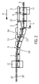
- FIG. 2 shows a schematic side view of the course of the staple chains 7 and thus the lower film 6 from the forming station 8 to the sealing station 12.
- the forming station 8 one or more consecutively and / or juxtaposed and forming a format wells 11 are formed in the lower film 6.
- the staple chains 7 are moved synchronously per working cycle by a film feed V in the direction of production R, in order to provide newly to be filled troughs of the insertion path 9 and the product insert belt 3.
- FIG. 2 further shows a schematic detail view of the insertion path 9 with the product insert belt 3, are promoted on the products 10 in the production direction R.
- the product inlay band 3 has a vertical height H in the area above the forming station 8.
- the course of the chain guide 30 from the forming station 8 to the sealing station 12 is approximately S-shaped.
- the chain guide 30 is aligned horizontally in the areas of the forming station 8 and the sealing station 12 and in the region of the insertion path 9, the chain guide 30 has a rising from the forming station 8 to the sealing station 12 course.
- the upper guide surface O along the forming station 8 has a horizontal orientation and a first vertical distance V1 from a footprint A.
- the upper guide surface O along the sealing station 12 has a horizontal orientation and a second vertical distance V2 from a footprint A.
- the chain guide in each case has a radial course with a radius RA of 500 mm to 1000 mm. On the one hand, this ensures gentle transitions of the chain guide 30, so there are no kinks in the wells 11, especially when using rigid films. On the other hand, the insertion path 9 should not be unnecessarily long in order to keep the overall machine length of the thermoforming packaging machine 1 as short as possible.
- the product inlay band 3 is connected, for example, to the machine frame 4 by means of a first adjusting device 23 and a second adjusting device 24.
- a first adjusting device 23 and a second adjusting device 24 For example, manual or power-operated settings of the product insert belt 3 can be carried out via the adjusting devices 23, 24.
- FIG. 3 shows a schematic plan view of the insertion path 9 with the product insert belt 3 and a product feed belt in a first phase.
- the product inlay band 3 comprises two belts 3a and 3b, which are respectively provided for a track S1 and S2 for the product supply.
- a track S1, S2 is defined by the successive troughs in production direction R troughs 11.
- the two belts 3a, 3b are each driven via separately controllable drives 21 a, 21 b.
- the product infeed belt 3 is assigned a product supply belt 30 for feeding products 10 in a first track S1 and in a second track S2 in accordance with the number of tracks of the thermoforming packaging machine 1.
- a separation point 31 is provided and before the separation point 31, a device 32 for detecting the products 10 on the product feed belt 30 is arranged.
- the device 32 may, for example, have a vision system common to both lanes, or a sensor 33 may be provided for each lane S1, S2 to detect a leading edge 34 of the product 10 and forward this information to the controller 18.
- the distance A between two successive products 10 and their leading edges 34 of a track S1, S2 preferably corresponds to the distance A 'of two successive wells 11, for example, to insert a group of four products 10, a so-called format.
- the group in FIG. 3 2 two times corresponds to products 1c, 2c, 1d, 2d, and this group of products 10 can be inserted into the troughs 11 with a common and synchronous feed movement of product inlay tape 3 and staple chains 7.
- the product feed belt 30 has a drive 30a, preferably a servomotor drive analogous to the drives 21a, 21b.
- the products 3c, 4c, 3d, 4d, which can be fed on the product feed belt 30, have, as in FIG. 3 6 illustrates a difference D in the direction of production R with respect to the leading edges 34 of two adjacent products 3c and 3d detected by means 32 while the products 10 are in or passing through their measurement range.
- the belts 3a, 3b are shown in an advancing movement to transport the group of products 1c, 2c, 1d, 2d to the front end thereof, in a subsequent power stroke, this group or even only two adjacent products 1c and 1d during a common feed with the staple chains 7 in the wells 11 insert.
- FIG. 4 shows a schematic plan view of the insertion path 9 with the product insert belt 3 and the product feed belt 30 in a second phase.
- the belt 3a of the first track S1 positions the product 2c at a position intended to produce a distance A from the product 2c to the subsequent newly picked-up product 3c when taking over the subsequent product 3c.
- this also performs the second band 3b for the products 2d and 3d, wherein the two bands 3a, 3b and their products 2c, 3c, 2d, 3d have the difference D, which is generated in the acquisition of the products 3c and 3d or automatically results.
- the product feed belt 30 is in the feed motion, see arrow.
- the first band 3a moves in this phase already shown synchronously with the product feed belt 30 and takes up the product 3c, while the second band 3b first synchronizes with the product feed belt 30 as soon as the next product 3d of the second track 2 comes to take over or .,
- the leading edge 34 is located at the separation point 31.
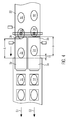
- FIG. 5 shows a schematic plan view of the insertion path 9 with the product insert belt 3 and the product feed belt in a third phase.
- the products 3c and 3d are completely taken over by the product feed belt 30 on the product insert belt 3 and the difference D can be compensated for by a relative movement of the two belts 3a, 3b to the leading edges 34 of the products 2c, 2d on a common virtual Line L transverse to the production direction R to position.
- the in FIG. 5 shown embodiment only moves the second Band 3b in the direction of the arrow to compensate for the difference D.
- the advance of the staple chains 7 stops and the product feed belt 30 does not accept any new products 4c, 4d.
- the two bands 3a, 3b are positioned on the insertion position for the next insertion process or transfer operation.
- This invention also includes a product inlay band 3 with more than two tracks or bands, and further groups with a different number of products 10 can be inserted into the recesses 11 during a loading process.
- the detection of the speed of the product supply belt 30 for synchronization with the belts 3a, 3b may be effected via a measuring system on the product supply belt 30 or on its drive 30a, which is connected to the controller 18 of the thermoforming packaging machine 1.
- the information of the speed may be transmitted via a bus system from the control of the product supply belt 30 to the controller 18 of the thermoforming packaging machine 1.
- the sensors 33 can be designed as optical sensors.
Abstract
Tiefziehverpackungsmaschine (1) mit wenigstens zwei Klammerketten (7) zum beidseitigen Halten einer Unterfolie (6) und zum Transportieren der Unterfolie (6) entlang einer Produktionsrichtung (R) der Tiefziehverpackungsmaschine (1), wobei die Klammerketten (7) in Kettenführungen (30) geführt sind, wobei die Tiefziehverpackungsmaschine (1) eine Formstation (8) zum Erzeugen von Mulden (11) in die Unterfolie (6), eine Siegelstation (12) und wenigstens eine Schneidstation (14) aufweist, die in dieser Reihenfolge entlang der Produktionsrichtung (R) an einem Maschinengestell (4) angeordnet sind, wobei sich die Kettenführungen (30) wenigstens von der Formstation (8) entlang einer Einlegestrecke (9) zur Siegelstation (12) erstrecken, wobei die Kettenführungen (30) jeweils eine obere Führungsfläche (0) und eine untere Führungsfläche (U) aufweisen, zwischen denen jeweils eine Klammerkette (7) geführt ist und die obere Führungsfläche (0) an bzw. entlang der Formstation (8) eine horizontale Ausrichtung aufweist und in diesem Abschnitt einen ersten vertikalen Abstand (V1) von einer Aufstellfläche (A) des Maschinengestells (4) der Tiefziehverpackungsmaschine (1) hat, wobei die Kettenführungen (30) an bzw. entlang der Siegelstation (12) eine horizontale Ausrichtung aufweisen und die obere Führungsfläche (0) in diesem Abschnitt einen zweiten vertikalen Abstand (V2) von der Aufstellfläche (A) hat, und der zweite Abstand (V2) größer ist als der erste Abstand (V1), sowie die Kettenführung (30) entlang der Einlegestrecke (9) wenigstens teilweise eine ansteigende Ausrichtung aufweist, wobei das Produkteinlegeband (3) wenigstens zwei separat antreibbare Bänder (3a, 3b) aufweist.Thermoforming packaging machine (1) with at least two staple chains (7) for holding a lower film (6) on both sides and for transporting the lower film (6) along a production direction (R) of the thermoforming packaging machine (1), wherein the staple chains (7) are housed in chain guides (30) wherein the thermoforming packaging machine (1) has a forming station (8) for producing depressions (11) in the lower film (6), a sealing station (12) and at least one cutting station (14) arranged in this order along the production direction ( R) are arranged on a machine frame (4), wherein the chain guides (30) extend at least from the forming station (8) along an insertion path (9) to the sealing station (12), the chain guides (30) each having an upper guide surface (0 ) and a lower guide surface (U), between each of which a staple chain (7) is guided and the upper guide surface (0) at or along the forming station (8) has a horizon Alle has orientation and in this section a first vertical distance (V1) of a footprint (A) of the machine frame (4) of the thermoforming packaging machine (1), wherein the chain guides (30) on or along the sealing station (12) has a horizontal orientation and the upper guide surface (0) in this section has a second vertical distance (V2) from the footprint (A), and the second distance (V2) is greater than the first distance (V1) and along the chain guide (30) the insertion path (9) has at least partially an ascending orientation, wherein the product insert belt (3) has at least two separately drivable belts (3a, 3b).
Description
Die Erfindung bezieht sich auf eine Tiefziehverpackungsmaschine gemäß dem Oberbegriff des Anspruchs 1 sowie auf ein Verfahren zum Betrieb einer Tiefziehverpackungsmaschine gemäß Anspruch 5.The invention relates to a thermoforming packaging machine according to the preamble of
Aus der
Aufgabe der vorliegenden Erfindung ist es, die Maschinenlänge einer Tiefziehverpackungsmaschine zu reduzieren und den Einlegevorgang von Produkten in geformte Mulden zu verbessern.The object of the present invention is to reduce the machine length of a thermoforming packaging machine and to improve the insertion process of products into molded troughs.
Diese Aufgabe wird gelöst durch eine Tiefziehverpackungsmaschine gemäß dem Anspruch 1 bzw. durch ein Verfahren gemäß dem Anspruch 5. Vorteilhafte Weiterbildungen der Erfindung sind in den Unteransprüchen angegeben.This object is achieved by a thermoforming packaging machine according to
Die erfindungsgemäße Tiefziehverpackungsmaschine weist wenigstens zwei Klammerketten zum beidseitigen Halten einer Unterfolie und zum Transportieren der Unterfolie entlang einer Produktionsrichtung der Tiefziehverpackungsmaschine auf, wobei die Klammerketten in Kettenführungen geführt sind. Die Kettenführungen weisen jeweils eine obere Führungsfläche und eine untere Führungsfläche auf, zwischen denen jeweils eine Klammerkette führbar ist. Die Tiefziehverpackungsmaschine weist eine Formstation zum Erzeugen von Mulden in eine Unterfolie, eine Siegelstation und wenigstens eine Schneidstation auf, die in dieser Reihenfolge entlang der Produktionsrichtung an einem Maschinengestell angeordnet sind, wobei sich die Kettenführungen wenigstens von der Formstation entlang einer Einlegestrecke zur Siegelstation erstrecken, und wobei die obere Führungsfläche an bzw. entlang der Formstation eine horizontale Ausrichtung aufweist und einen ersten vertikalen Abstand von einer Aufstellfläche des Maschinengestells der Tiefziehverpackungsmaschine hat, wobei die Kettenführungen an bzw. entlang der Siegelstation eine horizontale Ausrichtung aufweisen und die obere Führungsfläche einen zweiten vertikalen Abstand von der Aufstellfläche hat, wobei der zweite Abstand größer ist als der erste Abstand, sowie die Kettenführung entlang der Einlegestrecke wenigstens teilweise eine ansteigende Ausrichtung aufweist. Die erfindungsgemäße Tiefziehverpackungsmaschine zeichnet sich dadurch aus, dass das Produkteinlegeband wenigstens zwei separat antreibbare Bänder aufweist. Die Tiefziehverpackungsmaschine weist je ein Band pro Spur auf, wobei eine Spur durch in Produktionsrichtung aufeinanderfolgende Mulden definiert ist. Diese Ausführung einer Tiefziehverpackungsmaschine erlaubt eine kurze Einlegestrecke, da ein Produktzuführband Produkte auf einfache und prozesssichere Weise zumindest im Wesentlichen horizontal zuführen und in Mulden einlegen kann. Die separat antreibbaren Bänder ermöglichen eine Korrektur von unterschiedlich ankommenden Produkten zwischen den einzelnen Spuren, so dass die Einlegegenauigkeit der Produkte in die Mulden stark verbessert wird.The thermoforming packaging machine according to the invention has at least two staple chains for holding a lower film on both sides and for transporting the lower film along a production direction of the thermoforming packaging machine, wherein the staple chains are guided in chain guides. The chain guides each have an upper guide surface and a lower guide surface, between each of which a staple chain can be guided. The thermoforming packaging machine has a forming station for forming depressions in a lower film, a sealing station and at least one cutting station, which in this Sequence along the production direction are arranged on a machine frame, wherein the chain guides extend at least from the forming station along an insertion path to the sealing station, and wherein the upper guide surface on or along the forming station has a horizontal orientation and a first vertical distance from a footprint of the machine frame the thermoforming packaging machine, wherein the chain guides at or along the sealing station have a horizontal orientation and the upper guide surface has a second vertical distance from the footprint, wherein the second distance is greater than the first distance, as well as the chain guide along the insertion path at least partially has increasing orientation. The thermoforming packaging machine according to the invention is characterized in that the product inlay belt has at least two separately drivable belts. The thermoforming packaging machine has one band per track, wherein one track is defined by successive troughs in the direction of production. This embodiment of a thermoforming packaging machine allows a short insertion path, since a product feeding belt can deliver products in a simple and process-reliable manner, at least substantially horizontally, and place them in trays. The separately drivable belts allow a correction of different incoming products between the individual tracks, so that the insertion accuracy of the products in the wells is greatly improved.
Vorzugsweise ist eine Vorschubbewegung der Bänder zum Einlegen der Produkte in die Mulden synchron zueinander und synchron zu einer Vorschubbewegung der Klammerketten ausführbar. So kann die Platzierung des Produkts in der Mulde exakt erfolgen.Preferably, a feed movement of the belts for inserting the products into the troughs is synchronous with each other and synchronous to a feed movement of the staple chains executable. Thus, the placement of the product in the trough can be done exactly.
Bevorzugt ist eine Trennstelle zwischen dem Produkteinlegeband und einem direkt stromaufwärts vorgelagerten Produktzuführband vorgesehen, um die Lage von Produkten, die über ein Produktzuführband an die Tiefziehverpackungsmaschine herangeführt werden, zu verändern und an die Einlegebedingungen anzupassen.Preferably, a separation point between the product infeed belt and a directly upstream upstream product feed belt is provided in order to change the position of products which are introduced via a product feed belt to the thermoforming packaging machine, and adapt to the insertion conditions.
Dabei ist in einer vorteilhaften Ausführungsvariante vor der Trennstelle eine Einrichtung mit einem oder mehreren Sensoren vorgesehen, um die Position der Produkte für jede Spur des Produkteinlegebands zu erfassen. So können vorhandenen Ungenauigkeiten bezüglich der Lage der Produkte in Produktionsrichtung auf dem Produktzuführband erfasst werden und bereits bei der Übernahme auf das Produkteinlegeband berücksichtigt werden.In this case, in an advantageous embodiment variant, a device with one or more sensors is provided in front of the separation point in order to detect the position of the products for each track of the product insertion band. Thus, existing inaccuracies in the position of the products in the production direction on the product feed belt can be detected and taken into account already at the time of the takeover on the product infeed belt.
Ein erfindungsgemäßes Verfahren zum Betrieb einer zuvor beschriebenen Tiefziehverpackungsmaschine zeichnet sich dadurch aus, dass die Bänder des Produkteinlegebands derart angesteuert werden, dass bei der Übergabe der Produkte vom Produktzuführband die Bänder separat mit dem Produktzuführband angesteuert werden, um Positionsunterschiede benachbarter Produkte in Produktionsrichtung zu korrigieren. Dies verbessert den nachfolgenden Einlegeprozess und führt zu einer Verbesserung der Lagegenauigkeit der Produkte in den Mulden, um manuelle Nachkorrekturen durch eine Bedienperson zu vermeiden oder wenigstens zu reduzieren.A method according to the invention for operating a thermoforming packaging machine described above is characterized in that the belts of the product insert belt are controlled such that when transferring the products from the product supply belt, the belts are controlled separately with the product supply belt to correct positional differences of adjacent products in the production direction. This improves the subsequent loading process and leads to an improvement in the positional accuracy of the products in the troughs to avoid or at least reduce manual post-corrections by an operator.
Vorzugsweise wird bei der Übergabe des Produkts auf das jeweilige Band die Geschwindigkeit dieses Bands mit der Geschwindigkeit des Produktzuführbands synchronisiert, um die Kenntnis über die Lage des Produkts mittels einer Streckensteuerung nicht zu verlieren und/oder eine Verformung des Produkts zu verhindern.Preferably, upon transfer of the product to the respective belt, the speed of this belt is synchronized with the speed of the product supply belt so as not to lose knowledge of the position of the product by means of a line control and / or to prevent deformation of the product.
Bevorzugt wird mittels eines oder mehrerer Sensoren vor der Trennstelle die Position von nebeneinander benachbarten Produkten erfasst und diese Information an eine Steuerung der Tiefziehverpackungsmaschine übermittelt, wobei die Steuerung die Information über die Positionen auswertet und den Unterschied von einer Vorderkante eines ersten Produkts der ersten Spur zu der Vorderkante eines zweiten Produkts der zweiten Spur ermittelt. Somit kann eine Egalisierung bzw. ein Ausgleichen dieses Unterschiedes bei der Übernahme und vor dem Einlegen erfolgen und ein exaktes Einlegen erfolgen.Preferably, by means of one or more sensors in front of the separation point, the position of adjacent products is detected and this information is transmitted to a control of the thermoforming packaging machine, wherein the controller evaluates the information about the positions and the difference from a leading edge of a first product of the first track to the Front edge of a second product of the second track determined. Thus, a leveling or balancing this difference in the acquisition and before inserting done and make an exact insertion.
Dabei steuert die Steuerung die Bänder bei der Übernahme der Produkte jeweils bevorzugt so an, dass nach der Übernahme die Vorderkanten von in Produktionsrichtung aufeinander folgenden Produkten jeweils einer Spur einen vorgesehenen Abstand aufweisen, der vorzugsweise einem Abstand von aufeinanderfolgenden Mulden in der Unterfolie entspricht.In this case, the control system preferably controls the bands during the takeover of the products in such a way that, after the takeover, the leading edges of successive products in the production direction each have a predetermined distance, which preferably corresponds to a spacing of successive depressions in the lower foil.
Vorzugsweise erfolgt die Übernahme der Produkte durch das Produkteinlegeband, während der Vorschub der Klammerketten stillsteht.Preferably, the takeover of the products by the product insert belt, while the feed of the staple chains is stopped.
Im Folgenden wird ein vorteilhaftes Ausführungsbeispiel der Erfindung anhand einer Zeichnung näher dargestellt. Dabei zeigen:
Figur 1- eine schematische Seitenansicht einer Verpackungsanlage mit einer erfindungsgemäßen Tiefziehverpackungsmaschine und mit einem Produkteinlegeband,
Figur 2- eine schematische Seitenansicht des Verlaufs der Klammerketten von der Form- zur Siegelstation und der Einlegestrecke mit dem Produkteinlegeband,
Figur 3- eine schematische Draufsicht der Einlegestrecke mit dem Produkteinlegeband und einem Produktzuführband in einer ersten Phase,
- Figur 4
- eine schematische Draufsicht der Einlegestrecke mit dem Produkteinlegeband und dem Produktzuführband in einer zweiten Phase und,
- Figur 5
- eine schematische Draufsicht der Einlegestrecke mit dem Produkteinlegeband und dem Produktzuführband in einer dritten Phase..
- FIG. 1
- a schematic side view of a packaging system with a thermoforming packaging machine according to the invention and with a product inlay,
- FIG. 2
- a schematic side view of the course of the staple chains from the form to the sealing station and the insertion path with the product infeed belt,
- FIG. 3
- a schematic plan view of the insertion path with the product insert belt and a product feed belt in a first phase,
- FIG. 4
- a schematic plan view of the insertion path with the product infeed belt and the product feed belt in a second phase and,
- FIG. 5
- a schematic plan view of the insertion path with the product infeed belt and the product feed belt in a third phase ..
Gleiche Komponenten sind in den Figuren durchgängig mit gleichen Bezugszeichen versehen.The same components are provided throughout the figures with the same reference numerals.
Die Klammerketten 7 sind in einer Kettenführung 30, in
Der Verlauf der Kettenführung 30 von der Formstation 8 zur Siegelstation 12 ist etwa S-förmig ausgebildet. Die Kettenführung 30 ist in den Bereichen der Formstation 8 und der Siegelstation 12 horizontal ausgerichtet und im Bereich der Einlegestrecke 9 weist die Kettenführung 30 einen von der Formstation 8 zur Siegelstation 12 ansteigenden Verlauf auf. Die obere Führungsfläche O entlang der Formstation 8 weist eine horizontale Ausrichtung und einen ersten vertikalen Abstand V1 von einer Aufstellfläche A auf. Die obere Führungsfläche O entlang der Siegelstation 12 weist eine horizontale Ausrichtung und einen zweiten vertikalen Abstand V2 von einer Aufstellfläche A auf. Bei den Übergängen von der Formstation 8 zur Einlegestrecke 9 und von der Einlegestrecke 9 zur Siegelstation 12 weist die Kettenführung jeweils einen radialen Verlauf mit einem Radius RA von 500 mm bis 1000 mm auf. Dies sorgt einerseits für sanfte Übergänge der Kettenführung 30, damit keine Knicke in den Mulden 11 vor allem beim Einsatz von Hartfolien entstehen. Andererseits soll die Einlegestrecke 9 nicht unnötig lang ausgeführt sein, um die Gesamtmaschinenlänge der Tiefziehverpackungsmaschine 1 möglichst kurz zu halten.The course of the chain guide 30 from the forming
Das Produkteinlegeband 3 ist beispielsweise mittels einer ersten Verstellvorrichtung 23 und einer zweiten Verstellvorrichtung 24 mit dem Maschinengestell 4 verbunden. Über die Verstellvorrichtungen 23, 24 können beispielsweise manuelle oder kraftbetriebene Einstellungen des Produkteinlegebands 3 durchgeführt werden.The
In
Der Abstand A zwischen zwei aufeinanderfolgenden Produkten 10 bzw. deren Vorderkanten 34 einer Spur S1, S2 entspricht vorzugsweise dem Abstand A' von zwei aufeinanderfolgenden Mulden 11, um beispielsweise eine Gruppe von vier Produkten 10, ein sogenanntes Format, einzulegen. Die Gruppe, die in
Die auf dem Produktzuführband 30 zuführbaren Produkte 3c, 4c, 3d, 4d weisen wie in
Die Bänder 3a, 3b sind in einer Vorschubbewegung gezeigt, um die Gruppe von Produkten 1 c, 2c, 1 d, 2d, zur deren vorderen Ende zu transportieren, um in einem nachfolgenden Arbeitstakt diese Gruppe oder auch nur zwei benachbarten Produkten 1c und 1d während eines gemeinsamen Vorschubs mit den Klammerketten 7 in die Mulden 11 einzulegen.The
Anschließend werden die beiden Bänder 3a, 3b auf die Einlegeposition für den nächsten Einlegevorgang oder Übernahmevorgang positioniert.Subsequently, the two
Unter dieser Erfindung ist auch ein Produkteinlegeband 3 mit mehr als zwei Spuren bzw. Bändern umfasst, sowie können weitere Gruppen mit unterschiedlicher Anzahl von Produkten 10 bei einem Einlegevorgang in die Mulden 11 eingelegt werden. Die Erfassung der Geschwindigkeit des Produktzuführbands 30 zur Synchronisierung mit den Bändern 3a, 3b kann über ein Messsystem am Produktzuführband 30 oder an dessen Antrieb 30a, das mit der Steuerung 18 der Tiefziehverpackungsmaschine 1 verbunden ist, erfolgen. Alternativ kann die Information der Geschwindigkeit über ein Bussystem von der Steuerung des Produktzuführbands 30 an die Steuerung 18 der Tiefziehverpackungsmaschine 1 übertragen werden. Die Sensoren 33 können als optische Sensoren ausgeführt sein.This invention also includes a
Claims (9)
Applications Claiming Priority (2)
| Application Number | Priority Date | Filing Date | Title |
|---|---|---|---|
| DE202016000757.3U DE202016000757U1 (en) | 2016-02-03 | 2016-02-03 | Thermoforming packaging machine |
| EP16167440.3A EP3210895A3 (en) | 2016-02-03 | 2016-04-28 | Deep draw packaging machine |
Publications (3)
| Publication Number | Publication Date |
|---|---|
| EP3210896A2 true EP3210896A2 (en) | 2017-08-30 |
| EP3210896A3 EP3210896A3 (en) | 2017-10-04 |
| EP3210896B1 EP3210896B1 (en) | 2018-12-12 |
Family
ID=55638364
Family Applications (4)
| Application Number | Title | Priority Date | Filing Date |
|---|---|---|---|
| EP16167437.9A Withdrawn EP3202671A3 (en) | 2016-02-03 | 2016-04-28 | Deep draw packaging machine |
| EP16167442.9A Revoked EP3202673B1 (en) | 2016-02-03 | 2016-04-28 | Deep draw packaging machine |
| EP16167440.3A Withdrawn EP3210895A3 (en) | 2016-02-03 | 2016-04-28 | Deep draw packaging machine |
| EP16172828.2A Active EP3210896B1 (en) | 2016-02-03 | 2016-06-03 | Method for operating a deep draw packaging machine |
Family Applications Before (3)
| Application Number | Title | Priority Date | Filing Date |
|---|---|---|---|
| EP16167437.9A Withdrawn EP3202671A3 (en) | 2016-02-03 | 2016-04-28 | Deep draw packaging machine |
| EP16167442.9A Revoked EP3202673B1 (en) | 2016-02-03 | 2016-04-28 | Deep draw packaging machine |
| EP16167440.3A Withdrawn EP3210895A3 (en) | 2016-02-03 | 2016-04-28 | Deep draw packaging machine |
Country Status (5)
| Country | Link |
|---|---|
| US (1) | US20170217616A1 (en) |
| EP (4) | EP3202671A3 (en) |
| CN (1) | CN107031883A (en) |
| DE (3) | DE202016000757U1 (en) |
| ES (2) | ES2688921T3 (en) |
Families Citing this family (10)
| Publication number | Priority date | Publication date | Assignee | Title |
|---|---|---|---|---|
| DE202016000757U1 (en) | 2016-02-03 | 2016-03-10 | Multivac Sepp Haggenmüller Se & Co. Kg | Thermoforming packaging machine |
| DE102016214431A1 (en) * | 2016-08-04 | 2018-02-08 | Multivac Sepp Haggenmüller Se & Co. Kg | Thermoforming packaging machine with retaining strip |
| ES2805229T3 (en) * | 2016-10-28 | 2021-02-11 | Multivac Haggenmueller Kg | Deep Drawing Packaging Machine |
| EP3315423B1 (en) | 2016-10-28 | 2020-04-15 | MULTIVAC Sepp Haggenmüller SE & Co. KG | Deep draw packaging machine |
| DE102018204044A1 (en) | 2018-03-16 | 2019-09-19 | Multivac Sepp Haggenmüller Se & Co. Kg | Thermoforming packaging machine with film deflection |
| DE202018101469U1 (en) | 2018-03-16 | 2019-06-19 | Multivac Sepp Haggenmüller Se & Co. Kg | Thermoforming packaging machine with film deflection |
| DE102018204043A1 (en) * | 2018-03-16 | 2019-09-19 | Multivac Sepp Haggenmüller Se & Co. Kg | Transport device with locking mechanism |
| DE102018204049B4 (en) * | 2018-03-16 | 2020-10-22 | Multivac Sepp Haggenmüller Se & Co. Kg | Packaging machine with combined contamination and tamper protection |
| DE102018204042A1 (en) | 2018-03-16 | 2019-09-19 | Multivac Sepp Haggenmüller Se & Co. Kg | Thermoforming packaging machine with film deflection |
| CN111453049B (en) * | 2020-04-07 | 2021-08-31 | 兰陵县成大食品有限公司 | Full-automatic vacuum packaging machine food machinery |
Citations (2)
| Publication number | Priority date | Publication date | Assignee | Title |
|---|---|---|---|---|
| DE10224237A1 (en) | 2002-05-29 | 2003-12-11 | Convenience Food Sys Wallau | packaging |
| DE102006005405A1 (en) | 2006-02-03 | 2007-08-09 | Multivac Sepp Haggenmüller Gmbh & Co. Kg | Packaging machine, in particular roller or thermoforming machine, tray sealing machine or the like |
Family Cites Families (17)
| Publication number | Priority date | Publication date | Assignee | Title |
|---|---|---|---|---|
| US3354613A (en) * | 1965-04-28 | 1967-11-28 | Mahaffy & Harder Eng Co | Packaging apparatus with improved product loader |
| USRE29937E (en) * | 1974-02-15 | 1979-03-20 | Mahaffy & Harder Engineering Co. | Continuous movement packaging machine |
| DE2516583A1 (en) | 1975-04-16 | 1976-10-28 | Waldner Kg H | Belt feed arrgt. for packaging machine - conveys sliced portions on two crossing belt conveyors |
| GB8431291D0 (en) | 1984-12-12 | 1985-01-23 | Thurne Eng Co Ltd | Conveyor |
| US5009053A (en) * | 1987-03-26 | 1991-04-23 | Keith A. Langenbeck | Storage and transport tray and tray packing system |
| IT1238798B (en) | 1989-10-13 | 1993-09-03 | Stream Srl | APPARATUS TO APPROACH THEM, AT A PREFIXED DISTANCE, PRODUCTS THAT ADVANCE ALONG A CONVEYOR BELT. |
| US5810149A (en) | 1996-11-26 | 1998-09-22 | Formax, Inc. | Conveyor system |
| DE19824976A1 (en) | 1998-06-04 | 1999-12-09 | Kraemer & Grebe Kg | Method and device for producing packages |
| US6540063B1 (en) * | 2000-06-14 | 2003-04-01 | David M. Fallas | Conveyor assembly for providing selectively spaced products |
| DE10201182A1 (en) | 2002-01-14 | 2003-07-24 | Cfs Gmbh Kempten | positioning |
| US7065936B2 (en) * | 2002-12-18 | 2006-06-27 | Formax, Inc. | Fill and packaging apparatus |
| DE10312889B3 (en) * | 2003-03-22 | 2004-08-05 | CSAT Gesellschaft für Computer-Systeme und Automations-Technik mbH | Blister pack manufacturing device has markings provided by underlying foil detected for providing activation signals for printer used for printing overlying foil |
| ITMI20060865A1 (en) * | 2006-05-03 | 2007-11-04 | Gianmario Sala | BAG FILLING GROUP |
| PL2412632T3 (en) * | 2010-07-29 | 2013-10-31 | Multivac Haggenmueller Kg | Method and deep-draw packaging machine for filling packaging moulds with products |
| EP2807004B2 (en) | 2012-01-26 | 2022-09-21 | GEA Food Solutions Germany GmbH | Slicing in the package |
| EP2740677A1 (en) * | 2012-12-10 | 2014-06-11 | Multivac Sepp Haggenmüller GmbH & Co. KG | Transport device for deep draw packaging machine |
| DE202016000757U1 (en) | 2016-02-03 | 2016-03-10 | Multivac Sepp Haggenmüller Se & Co. Kg | Thermoforming packaging machine |
-
2016
- 2016-02-03 DE DE202016000757.3U patent/DE202016000757U1/en active Active
- 2016-04-28 EP EP16167437.9A patent/EP3202671A3/en not_active Withdrawn
- 2016-04-28 EP EP16167442.9A patent/EP3202673B1/en not_active Revoked
- 2016-04-28 EP EP16167440.3A patent/EP3210895A3/en not_active Withdrawn
- 2016-04-28 ES ES16167442.9T patent/ES2688921T3/en active Active
- 2016-04-28 DE DE202016008856.5U patent/DE202016008856U1/en active Active
- 2016-06-03 ES ES16172828T patent/ES2714359T3/en active Active
- 2016-06-03 EP EP16172828.2A patent/EP3210896B1/en active Active
- 2016-06-03 DE DE202016008849.2U patent/DE202016008849U1/en active Active
-
2017
- 2017-01-25 CN CN201710061150.7A patent/CN107031883A/en active Pending
- 2017-02-01 US US15/422,351 patent/US20170217616A1/en not_active Abandoned
Patent Citations (2)
| Publication number | Priority date | Publication date | Assignee | Title |
|---|---|---|---|---|
| DE10224237A1 (en) | 2002-05-29 | 2003-12-11 | Convenience Food Sys Wallau | packaging |
| DE102006005405A1 (en) | 2006-02-03 | 2007-08-09 | Multivac Sepp Haggenmüller Gmbh & Co. Kg | Packaging machine, in particular roller or thermoforming machine, tray sealing machine or the like |
Also Published As
| Publication number | Publication date |
|---|---|
| EP3202673A1 (en) | 2017-08-09 |
| DE202016000757U1 (en) | 2016-03-10 |
| EP3210896A3 (en) | 2017-10-04 |
| EP3210895A3 (en) | 2017-11-29 |
| EP3210896B1 (en) | 2018-12-12 |
| DE202016008849U1 (en) | 2020-02-10 |
| EP3202671A2 (en) | 2017-08-09 |
| EP3202671A3 (en) | 2017-10-04 |
| US20170217616A1 (en) | 2017-08-03 |
| ES2714359T3 (en) | 2019-05-28 |
| EP3210895A2 (en) | 2017-08-30 |
| ES2688921T3 (en) | 2018-11-07 |
| CN107031883A (en) | 2017-08-11 |
| EP3202673B1 (en) | 2018-09-12 |
| DE202016008856U1 (en) | 2020-02-27 |
Similar Documents
| Publication | Publication Date | Title |
|---|---|---|
| EP3210896B1 (en) | Method for operating a deep draw packaging machine | |
| EP1595797B1 (en) | Packaging machine and method of feeding containers in a packaging machine | |
| EP3487794B1 (en) | Device and method for handling moved piece goods, and a conveying, processing and/or packaging system having a device for handling moved piece goods | |
| EP2860119B1 (en) | Deep draw packaging machine and method | |
| EP2792623B1 (en) | Device and method for forming a predefined formation on a conveyor belt | |
| EP3615459A1 (en) | Apparatus and method for transporting products, in particular for packaging machines | |
| EP2818421A1 (en) | Tray closing machine with tray supply and method for a packaging system | |
| EP2574431A1 (en) | All-in-one cutting station and method for separating packages | |
| EP2517963B1 (en) | Packaging machine with transport device | |
| EP3339221A2 (en) | Method and device for handling products | |
| EP3037370A1 (en) | Packaging system | |
| EP1636097B1 (en) | Device and method for processing packages which are continuously prepared on carrier elements | |
| EP3350098B1 (en) | Method and device for producing packets of cigarettes | |
| EP3539910B1 (en) | Conveyor belt system to build a predefined arrangement of products | |
| EP3643650B1 (en) | Method for the timed feeding of material blanks into a packaging machine | |
| EP3009380B1 (en) | Grouping method and grouping device for generating and bringing together groups of items from a plurality of items | |
| EP3483077B1 (en) | Method for positioning food products | |
| EP3023337B1 (en) | Method for controlling a folding box glueing machine with a subsequent device for packing | |
| EP3025587A1 (en) | Device and method for transferring sausage portions | |
| DE102011104187B4 (en) | Method for automatic teaching of parameters | |
| EP2895313A1 (en) | Method and device for labelling a conical plastic container and banderole provided for this |
Legal Events
| Date | Code | Title | Description |
|---|---|---|---|
| REG | Reference to a national code |
Ref country code: DE Ref legal event code: R138 Ref document number: 202016008849 Country of ref document: DE Free format text: GERMAN DOCUMENT NUMBER IS 502016002764 |
|
| PUAI | Public reference made under article 153(3) epc to a published international application that has entered the european phase |
Free format text: ORIGINAL CODE: 0009012 |
|
| STAA | Information on the status of an ep patent application or granted ep patent |
Free format text: STATUS: THE APPLICATION HAS BEEN PUBLISHED |
|
| AK | Designated contracting states |
Kind code of ref document: A2 Designated state(s): AL AT BE BG CH CY CZ DE DK EE ES FI FR GB GR HR HU IE IS IT LI LT LU LV MC MK MT NL NO PL PT RO RS SE SI SK SM TR |
|
| AX | Request for extension of the european patent |
Extension state: BA ME |
|
| PUAL | Search report despatched |
Free format text: ORIGINAL CODE: 0009013 |
|
| AK | Designated contracting states |
Kind code of ref document: A3 Designated state(s): AL AT BE BG CH CY CZ DE DK EE ES FI FR GB GR HR HU IE IS IT LI LT LU LV MC MK MT NL NO PL PT RO RS SE SI SK SM TR |
|
| AX | Request for extension of the european patent |
Extension state: BA ME |
|
| RIC1 | Information provided on ipc code assigned before grant |
Ipc: B65B 9/04 20060101ALI20170831BHEP Ipc: B65B 41/12 20060101AFI20170831BHEP |
|
| STAA | Information on the status of an ep patent application or granted ep patent |
Free format text: STATUS: REQUEST FOR EXAMINATION WAS MADE |
|
| 17P | Request for examination filed |
Effective date: 20180312 |
|
| RBV | Designated contracting states (corrected) |
Designated state(s): AL AT BE BG CH CY CZ DE DK EE ES FI FR GB GR HR HU IE IS IT LI LT LU LV MC MK MT NL NO PL PT RO RS SE SI SK SM TR |
|
| GRAP | Despatch of communication of intention to grant a patent |
Free format text: ORIGINAL CODE: EPIDOSNIGR1 |
|
| STAA | Information on the status of an ep patent application or granted ep patent |
Free format text: STATUS: GRANT OF PATENT IS INTENDED |
|
| INTG | Intention to grant announced |
Effective date: 20180705 |
|
| GRAS | Grant fee paid |
Free format text: ORIGINAL CODE: EPIDOSNIGR3 |
|
| GRAA | (expected) grant |
Free format text: ORIGINAL CODE: 0009210 |
|
| STAA | Information on the status of an ep patent application or granted ep patent |
Free format text: STATUS: THE PATENT HAS BEEN GRANTED |
|
| AK | Designated contracting states |
Kind code of ref document: B1 Designated state(s): AL AT BE BG CH CY CZ DE DK EE ES FI FR GB GR HR HU IE IS IT LI LT LU LV MC MK MT NL NO PL PT RO RS SE SI SK SM TR |
|
| REG | Reference to a national code |
Ref country code: GB Ref legal event code: FG4D Free format text: NOT ENGLISH |
|
| REG | Reference to a national code |
Ref country code: CH Ref legal event code: EP |
|
| REG | Reference to a national code |
Ref country code: AT Ref legal event code: REF Ref document number: 1075667 Country of ref document: AT Kind code of ref document: T Effective date: 20181215 |
|
| REG | Reference to a national code |
Ref country code: DE Ref legal event code: R096 Ref document number: 502016002764 Country of ref document: DE |
|
| REG | Reference to a national code |
Ref country code: IE Ref legal event code: FG4D Free format text: LANGUAGE OF EP DOCUMENT: GERMAN |
|
| REG | Reference to a national code |
Ref country code: NL Ref legal event code: FP |
|
| REG | Reference to a national code |
Ref country code: LT Ref legal event code: MG4D |
|
| PG25 | Lapsed in a contracting state [announced via postgrant information from national office to epo] |
Ref country code: FI Free format text: LAPSE BECAUSE OF FAILURE TO SUBMIT A TRANSLATION OF THE DESCRIPTION OR TO PAY THE FEE WITHIN THE PRESCRIBED TIME-LIMIT Effective date: 20181212 Ref country code: NO Free format text: LAPSE BECAUSE OF FAILURE TO SUBMIT A TRANSLATION OF THE DESCRIPTION OR TO PAY THE FEE WITHIN THE PRESCRIBED TIME-LIMIT Effective date: 20190312 Ref country code: HR Free format text: LAPSE BECAUSE OF FAILURE TO SUBMIT A TRANSLATION OF THE DESCRIPTION OR TO PAY THE FEE WITHIN THE PRESCRIBED TIME-LIMIT Effective date: 20181212 Ref country code: BG Free format text: LAPSE BECAUSE OF FAILURE TO SUBMIT A TRANSLATION OF THE DESCRIPTION OR TO PAY THE FEE WITHIN THE PRESCRIBED TIME-LIMIT Effective date: 20190312 Ref country code: LT Free format text: LAPSE BECAUSE OF FAILURE TO SUBMIT A TRANSLATION OF THE DESCRIPTION OR TO PAY THE FEE WITHIN THE PRESCRIBED TIME-LIMIT Effective date: 20181212 Ref country code: LV Free format text: LAPSE BECAUSE OF FAILURE TO SUBMIT A TRANSLATION OF THE DESCRIPTION OR TO PAY THE FEE WITHIN THE PRESCRIBED TIME-LIMIT Effective date: 20181212 |
|
| REG | Reference to a national code |
Ref country code: ES Ref legal event code: FG2A Ref document number: 2714359 Country of ref document: ES Kind code of ref document: T3 Effective date: 20190528 |
|
| PG25 | Lapsed in a contracting state [announced via postgrant information from national office to epo] |
Ref country code: AL Free format text: LAPSE BECAUSE OF FAILURE TO SUBMIT A TRANSLATION OF THE DESCRIPTION OR TO PAY THE FEE WITHIN THE PRESCRIBED TIME-LIMIT Effective date: 20181212 Ref country code: RS Free format text: LAPSE BECAUSE OF FAILURE TO SUBMIT A TRANSLATION OF THE DESCRIPTION OR TO PAY THE FEE WITHIN THE PRESCRIBED TIME-LIMIT Effective date: 20181212 Ref country code: SE Free format text: LAPSE BECAUSE OF FAILURE TO SUBMIT A TRANSLATION OF THE DESCRIPTION OR TO PAY THE FEE WITHIN THE PRESCRIBED TIME-LIMIT Effective date: 20181212 Ref country code: GR Free format text: LAPSE BECAUSE OF FAILURE TO SUBMIT A TRANSLATION OF THE DESCRIPTION OR TO PAY THE FEE WITHIN THE PRESCRIBED TIME-LIMIT Effective date: 20190313 |
|
| PG25 | Lapsed in a contracting state [announced via postgrant information from national office to epo] |
Ref country code: PL Free format text: LAPSE BECAUSE OF FAILURE TO SUBMIT A TRANSLATION OF THE DESCRIPTION OR TO PAY THE FEE WITHIN THE PRESCRIBED TIME-LIMIT Effective date: 20181212 Ref country code: PT Free format text: LAPSE BECAUSE OF FAILURE TO SUBMIT A TRANSLATION OF THE DESCRIPTION OR TO PAY THE FEE WITHIN THE PRESCRIBED TIME-LIMIT Effective date: 20190412 Ref country code: CZ Free format text: LAPSE BECAUSE OF FAILURE TO SUBMIT A TRANSLATION OF THE DESCRIPTION OR TO PAY THE FEE WITHIN THE PRESCRIBED TIME-LIMIT Effective date: 20181212 |
|
| PG25 | Lapsed in a contracting state [announced via postgrant information from national office to epo] |
Ref country code: RO Free format text: LAPSE BECAUSE OF FAILURE TO SUBMIT A TRANSLATION OF THE DESCRIPTION OR TO PAY THE FEE WITHIN THE PRESCRIBED TIME-LIMIT Effective date: 20181212 Ref country code: IS Free format text: LAPSE BECAUSE OF FAILURE TO SUBMIT A TRANSLATION OF THE DESCRIPTION OR TO PAY THE FEE WITHIN THE PRESCRIBED TIME-LIMIT Effective date: 20190412 Ref country code: SK Free format text: LAPSE BECAUSE OF FAILURE TO SUBMIT A TRANSLATION OF THE DESCRIPTION OR TO PAY THE FEE WITHIN THE PRESCRIBED TIME-LIMIT Effective date: 20181212 Ref country code: SM Free format text: LAPSE BECAUSE OF FAILURE TO SUBMIT A TRANSLATION OF THE DESCRIPTION OR TO PAY THE FEE WITHIN THE PRESCRIBED TIME-LIMIT Effective date: 20181212 Ref country code: EE Free format text: LAPSE BECAUSE OF FAILURE TO SUBMIT A TRANSLATION OF THE DESCRIPTION OR TO PAY THE FEE WITHIN THE PRESCRIBED TIME-LIMIT Effective date: 20181212 |
|
| REG | Reference to a national code |
Ref country code: DE Ref legal event code: R026 Ref document number: 502016002764 Country of ref document: DE |
|
| PLBI | Opposition filed |
Free format text: ORIGINAL CODE: 0009260 |
|
| PLAX | Notice of opposition and request to file observation + time limit sent |
Free format text: ORIGINAL CODE: EPIDOSNOBS2 |
|
| 26 | Opposition filed |
Opponent name: GEA FOOD SOLUTIONS GERMANY GMBH Effective date: 20190912 |
|
| PG25 | Lapsed in a contracting state [announced via postgrant information from national office to epo] |
Ref country code: DK Free format text: LAPSE BECAUSE OF FAILURE TO SUBMIT A TRANSLATION OF THE DESCRIPTION OR TO PAY THE FEE WITHIN THE PRESCRIBED TIME-LIMIT Effective date: 20181212 Ref country code: SI Free format text: LAPSE BECAUSE OF FAILURE TO SUBMIT A TRANSLATION OF THE DESCRIPTION OR TO PAY THE FEE WITHIN THE PRESCRIBED TIME-LIMIT Effective date: 20181212 |
|
| PLBB | Reply of patent proprietor to notice(s) of opposition received |
Free format text: ORIGINAL CODE: EPIDOSNOBS3 |
|
| PG25 | Lapsed in a contracting state [announced via postgrant information from national office to epo] |
Ref country code: MC Free format text: LAPSE BECAUSE OF FAILURE TO SUBMIT A TRANSLATION OF THE DESCRIPTION OR TO PAY THE FEE WITHIN THE PRESCRIBED TIME-LIMIT Effective date: 20181212 |
|
| REG | Reference to a national code |
Ref country code: CH Ref legal event code: PL |
|
| REG | Reference to a national code |
Ref country code: BE Ref legal event code: MM Effective date: 20190630 |
|
| PG25 | Lapsed in a contracting state [announced via postgrant information from national office to epo] |
Ref country code: TR Free format text: LAPSE BECAUSE OF FAILURE TO SUBMIT A TRANSLATION OF THE DESCRIPTION OR TO PAY THE FEE WITHIN THE PRESCRIBED TIME-LIMIT Effective date: 20181212 |
|
| PG25 | Lapsed in a contracting state [announced via postgrant information from national office to epo] |
Ref country code: IE Free format text: LAPSE BECAUSE OF NON-PAYMENT OF DUE FEES Effective date: 20190603 |
|
| PG25 | Lapsed in a contracting state [announced via postgrant information from national office to epo] |
Ref country code: LI Free format text: LAPSE BECAUSE OF NON-PAYMENT OF DUE FEES Effective date: 20190630 Ref country code: LU Free format text: LAPSE BECAUSE OF NON-PAYMENT OF DUE FEES Effective date: 20190603 Ref country code: CH Free format text: LAPSE BECAUSE OF NON-PAYMENT OF DUE FEES Effective date: 20190630 Ref country code: BE Free format text: LAPSE BECAUSE OF NON-PAYMENT OF DUE FEES Effective date: 20190630 |
|
| PG25 | Lapsed in a contracting state [announced via postgrant information from national office to epo] |
Ref country code: CY Free format text: LAPSE BECAUSE OF FAILURE TO SUBMIT A TRANSLATION OF THE DESCRIPTION OR TO PAY THE FEE WITHIN THE PRESCRIBED TIME-LIMIT Effective date: 20181212 |
|
| PG25 | Lapsed in a contracting state [announced via postgrant information from national office to epo] |
Ref country code: HU Free format text: LAPSE BECAUSE OF FAILURE TO SUBMIT A TRANSLATION OF THE DESCRIPTION OR TO PAY THE FEE WITHIN THE PRESCRIBED TIME-LIMIT; INVALID AB INITIO Effective date: 20160603 Ref country code: MT Free format text: LAPSE BECAUSE OF FAILURE TO SUBMIT A TRANSLATION OF THE DESCRIPTION OR TO PAY THE FEE WITHIN THE PRESCRIBED TIME-LIMIT Effective date: 20181212 |
|
| REG | Reference to a national code |
Ref country code: DE Ref legal event code: R100 Ref document number: 502016002764 Country of ref document: DE |
|
| PG25 | Lapsed in a contracting state [announced via postgrant information from national office to epo] |
Ref country code: MK Free format text: LAPSE BECAUSE OF FAILURE TO SUBMIT A TRANSLATION OF THE DESCRIPTION OR TO PAY THE FEE WITHIN THE PRESCRIBED TIME-LIMIT Effective date: 20181212 |
|
| PLCK | Communication despatched that opposition was rejected |
Free format text: ORIGINAL CODE: EPIDOSNREJ1 |
|
| REG | Reference to a national code |
Ref country code: AT Ref legal event code: MM01 Ref document number: 1075667 Country of ref document: AT Kind code of ref document: T Effective date: 20210603 |
|
| PG25 | Lapsed in a contracting state [announced via postgrant information from national office to epo] |
Ref country code: AT Free format text: LAPSE BECAUSE OF NON-PAYMENT OF DUE FEES Effective date: 20210603 |
|
| PLBN | Opposition rejected |
Free format text: ORIGINAL CODE: 0009273 |
|
| STAA | Information on the status of an ep patent application or granted ep patent |
Free format text: STATUS: OPPOSITION REJECTED |
|
| 27O | Opposition rejected |
Effective date: 20211130 |
|
| PGFP | Annual fee paid to national office [announced via postgrant information from national office to epo] |
Ref country code: NL Payment date: 20230620 Year of fee payment: 8 Ref country code: FR Payment date: 20230622 Year of fee payment: 8 Ref country code: DE Payment date: 20230620 Year of fee payment: 8 |
|
| P01 | Opt-out of the competence of the unified patent court (upc) registered |
Effective date: 20230801 |
|
| PGFP | Annual fee paid to national office [announced via postgrant information from national office to epo] |
Ref country code: IT Payment date: 20230630 Year of fee payment: 8 Ref country code: GB Payment date: 20230622 Year of fee payment: 8 Ref country code: ES Payment date: 20230719 Year of fee payment: 8 |