EP2818421A1 - Tray closing machine with tray supply and method for a packaging system - Google Patents
Tray closing machine with tray supply and method for a packaging system Download PDFInfo
- Publication number
- EP2818421A1 EP2818421A1 EP13173591.2A EP13173591A EP2818421A1 EP 2818421 A1 EP2818421 A1 EP 2818421A1 EP 13173591 A EP13173591 A EP 13173591A EP 2818421 A1 EP2818421 A1 EP 2818421A1
- Authority
- EP
- European Patent Office
- Prior art keywords
- trays
- tray
- chain
- feeder
- pull
- Prior art date
- Legal status (The legal status is an assumption and is not a legal conclusion. Google has not performed a legal analysis and makes no representation as to the accuracy of the status listed.)
- Withdrawn
Links
Images


Classifications
-
- B—PERFORMING OPERATIONS; TRANSPORTING
- B65—CONVEYING; PACKING; STORING; HANDLING THIN OR FILAMENTARY MATERIAL
- B65B—MACHINES, APPARATUS OR DEVICES FOR, OR METHODS OF, PACKAGING ARTICLES OR MATERIALS; UNPACKING
- B65B7/00—Closing containers or receptacles after filling
- B65B7/16—Closing semi-rigid or rigid containers or receptacles not deformed by, or not taking-up shape of, contents, e.g. boxes or cartons
- B65B7/162—Closing semi-rigid or rigid containers or receptacles not deformed by, or not taking-up shape of, contents, e.g. boxes or cartons by feeding web material to securing means
- B65B7/164—Securing by heat-sealing
-
- B—PERFORMING OPERATIONS; TRANSPORTING
- B65—CONVEYING; PACKING; STORING; HANDLING THIN OR FILAMENTARY MATERIAL
- B65B—MACHINES, APPARATUS OR DEVICES FOR, OR METHODS OF, PACKAGING ARTICLES OR MATERIALS; UNPACKING
- B65B31/00—Packaging articles or materials under special atmospheric or gaseous conditions; Adding propellants to aerosol containers
- B65B31/02—Filling, closing, or filling and closing, containers or wrappers in chambers maintained under vacuum or superatmospheric pressure or containing a special atmosphere, e.g. of inert gas
- B65B31/025—Filling, closing, or filling and closing, containers or wrappers in chambers maintained under vacuum or superatmospheric pressure or containing a special atmosphere, e.g. of inert gas specially adapted for rigid or semi-rigid containers
- B65B31/028—Filling, closing, or filling and closing, containers or wrappers in chambers maintained under vacuum or superatmospheric pressure or containing a special atmosphere, e.g. of inert gas specially adapted for rigid or semi-rigid containers closed by a lid sealed to the upper rim of the container, e.g. tray-like container
-
- B—PERFORMING OPERATIONS; TRANSPORTING
- B65—CONVEYING; PACKING; STORING; HANDLING THIN OR FILAMENTARY MATERIAL
- B65B—MACHINES, APPARATUS OR DEVICES FOR, OR METHODS OF, PACKAGING ARTICLES OR MATERIALS; UNPACKING
- B65B35/00—Supplying, feeding, arranging or orientating articles to be packaged
- B65B35/30—Arranging and feeding articles in groups
- B65B35/36—Arranging and feeding articles in groups by grippers
-
- B—PERFORMING OPERATIONS; TRANSPORTING
- B65—CONVEYING; PACKING; STORING; HANDLING THIN OR FILAMENTARY MATERIAL
- B65B—MACHINES, APPARATUS OR DEVICES FOR, OR METHODS OF, PACKAGING ARTICLES OR MATERIALS; UNPACKING
- B65B35/00—Supplying, feeding, arranging or orientating articles to be packaged
- B65B35/30—Arranging and feeding articles in groups
- B65B35/44—Arranging and feeding articles in groups by endless belts or chains
-
- B—PERFORMING OPERATIONS; TRANSPORTING
- B65—CONVEYING; PACKING; STORING; HANDLING THIN OR FILAMENTARY MATERIAL
- B65B—MACHINES, APPARATUS OR DEVICES FOR, OR METHODS OF, PACKAGING ARTICLES OR MATERIALS; UNPACKING
- B65B43/00—Forming, feeding, opening or setting-up containers or receptacles in association with packaging
- B65B43/42—Feeding or positioning bags, boxes, or cartons in the distended, opened, or set-up state; Feeding preformed rigid containers, e.g. tins, capsules, glass tubes, glasses, to the packaging position; Locating containers or receptacles at the filling position; Supporting containers or receptacles during the filling operation
- B65B43/46—Feeding or positioning bags, boxes, or cartons in the distended, opened, or set-up state; Feeding preformed rigid containers, e.g. tins, capsules, glass tubes, glasses, to the packaging position; Locating containers or receptacles at the filling position; Supporting containers or receptacles during the filling operation using grippers
-
- B—PERFORMING OPERATIONS; TRANSPORTING
- B65—CONVEYING; PACKING; STORING; HANDLING THIN OR FILAMENTARY MATERIAL
- B65B—MACHINES, APPARATUS OR DEVICES FOR, OR METHODS OF, PACKAGING ARTICLES OR MATERIALS; UNPACKING
- B65B43/00—Forming, feeding, opening or setting-up containers or receptacles in association with packaging
- B65B43/42—Feeding or positioning bags, boxes, or cartons in the distended, opened, or set-up state; Feeding preformed rigid containers, e.g. tins, capsules, glass tubes, glasses, to the packaging position; Locating containers or receptacles at the filling position; Supporting containers or receptacles during the filling operation
- B65B43/52—Feeding or positioning bags, boxes, or cartons in the distended, opened, or set-up state; Feeding preformed rigid containers, e.g. tins, capsules, glass tubes, glasses, to the packaging position; Locating containers or receptacles at the filling position; Supporting containers or receptacles during the filling operation using roller-ways or endless conveyors
-
- B—PERFORMING OPERATIONS; TRANSPORTING
- B65—CONVEYING; PACKING; STORING; HANDLING THIN OR FILAMENTARY MATERIAL
- B65G—TRANSPORT OR STORAGE DEVICES, e.g. CONVEYORS FOR LOADING OR TIPPING, SHOP CONVEYOR SYSTEMS OR PNEUMATIC TUBE CONVEYORS
- B65G47/00—Article or material-handling devices associated with conveyors; Methods employing such devices
- B65G47/22—Devices influencing the relative position or the attitude of articles during transit by conveyors
- B65G47/26—Devices influencing the relative position or the attitude of articles during transit by conveyors arranging the articles, e.g. varying spacing between individual articles
Definitions
- the invention relates to a tray sealing machine, also called tray sealer, according to the preamble of claim 1.
- a tray sealer which comprises at least two feed belts for forming and positioning, for the gripper system, a group of trays, also referred to as trays, at corresponding distances from one another so that the trays can be transferred from the gripper system to the sealing station.
- the product-filled trays are provided to the feed belts by an intermittently operating chain feeder and are taken up in a start / stop operation by the first upstream feed belt, the so-called collector belt, of the tray sealing machine.
- the trays may be stopped prior to the first feed belt by means of a stopper and provided as buffered juxtaposed trays.
- An intermittently operating chain feed in which the trays are manually filled with products along the transport path, is disadvantageous and not ergonomic for the operating personnel. Much better is manually inserted a continuously running chain feeder.
- a continuously operated tray feeder is in the not yet published EP 12006757 the applicant himself disclosed.
- the trays are provided on a continuously running chain feeder at a predetermined distance from each other to the two feeder belts for picking up and grouping and positioning for the gripper system of the tray seaming machine.
- the trays transported on the chain feeder are automatically filled, for example, by fillers moving along with the chain feeder.
- a gap between the groups of trays which is advantageous for the intermittent gripper system, is already provided on the chain feed, so that the feed belts are independent of at least a certain period of time the delivery of the trays by the chain feeder can transport the group of trays to a position at which the gripper system removes them from the second feed belt and a sealing station of the tray sealing machine supplies. Since only one complete group can be processed in the sealing station or a lid foil may be sealed onto the tray rim, it must be ensured that the defined distribution of trays and gaps is maintained on the chain guide.
- Errors can be detected by checking for presence of trays by means of sensors, but in the event of a fault a correction must be made and the chain feeder stopped. Errors caused by the operating personnel, for example due to a missing tray or a tray incorrectly placed in the gap, lead to the stopping of the tray closing machine and, consequently, the chain feed, which means an increase in downtimes.
- the object of the present invention is to provide a tray sealing machine with a tray feeder for a continuously operated chain feeder for a tray closing machine and a method for operating such a tray feeder, which no longer has the disadvantages mentioned above, so that in particular a gap between groups of Trays on a chain feeder can be omitted.
- the tray feed according to the invention for receiving trays from a continuously running chain feed and for grouping these trays is characterized in that the tray feed has at least one first and one second pull chain, each with its own drive and slide elements.
- the pull chains are operable separately from each other and allow a group of trays to be picked up from a chain feeder by means of a first pull chain and at the same time independently positioning the group of trays for further transport into a sealing station by a gripper system of a tray closing machine by means of a second pull chain.
- the slide elements attached to the draw chains transport the trays.
- a pull chain can be provided as a single chain with single-sided slide elements.
- the chain may be designed as a link chain, a toothed belt or the like.
- the pull chain can also have two parallel and jointly driven chains or belts, wherein the slider elements are arranged between the chains and attached with their ends to each one of the two chains.
- train chain in the context of the invention means that such a chain can carry a "train” of trays, i. a group of shells with a certain number, which are arranged one behind the other in the transport direction.
- the length of the train that is to say the number of shells arranged one behind the other in a group, can be predetermined, for example, by the number of sliding elements connected to the pull chain.
- the pull chain As soon as a pull chain at the end of the tray feed is freed from the trays it is transporting, it may possibly be returned to the transfer point at the beginning of the tray feed at high speed. There, the pull chain preferably arrives in time so that it can take over again without a slowing down of the influx of shells handed over the completion of another train, first shell again.
- the pull chains are configured to transport a single group of trays, with the distances of the individual trays of a group from one another being formed when the trays are taken over from the chain feed to the pull chain.
- the number of the group of trays corresponds to the number of trays which are removed with a transport movement by the gripper system of the tray sealing machine from the pull chain and thus from the Trayzu Installation and transferred to a sealing station.
- the train chains are configured to be able to transport a group of trays at several sections along their course, the groups each having an equal number of trays. This is particularly advantageous for a large number of trays in a group, longer transport distances or further filling of the trays with an example liquid or pasty product on the Trayzu exit itself, wherein provided in the case of further filling in the tray delivery at least a third pull chain should be.
- the pull chain here thus comprises at least one section on which a train or a group of trays can be received, as well as remaining, free sections.
- this traction chain can be moved forward with possibly increased speed so that at the beginning of Trayzu operation again a section for receiving a new train of trays is provided.
- the pull chain along its course has several sections for receiving a train of trays. Because then the pull chain only has to be moved forward by such a short distance that the next free section for receiving trays is provided at the starting point of the tray feed.
- the train chains are preferably superimposed along a common track to subsequently transport the groups of trays along the common track.
- the track is the path along which the trays are transported in the transport direction.
- the fact that the tension chains are provided "superimposed" along a common track means that the path along which the trays move in the transport direction (for example in direct extension of a corresponding transport path along the chain feed) is swept by the slide elements of all tension chains.
- each train chain having a first and a second transport chain, one of which is arranged in the conveying direction right and the other in the conveying direction on the left side next to the path taken by the trays.
- the two transport chains assigned to a common pull chain can be connected to one another in particular by sliding elements.
- a lifting device is provided to provide the trays for onward transport by means of a gripper system of a tray sealing machine.
- the lifting device bridges the slider elements of the pull chain so that the group of trays can be transported barrier-free by means of the gripper system into the sealing station of the tray closing machine.
- a tray sealing machine comprises the tray feed according to the invention in order to increase the power or to reduce downtimes.
- the group of trays preferably has a number equal to the number of trays which are picked up by the gripper system from the tray feeder and transferred to the sealing station of the tray seaming machine, since an absent tray, for example, can cause problems in processing in the sealing station , For example, by gluing a lid film on the sealing tool lower part in the region of the missing tray.
- the Trayzu Equipment receives trays and thereby generates a defined distance between the successive trays by means of the slide elements of the tension chains.
- the distances of the slide elements for a group of trays are the same and are in relation to grippers of the gripper system.
- a sensor is provided at the downstream end of the chain feeder in the direction of transport to detect the presence of a tray prior to transfer to the tray feeder. This ensures that a group on a pull chain always has the necessary number of trays and no tray is missing before or between the slider elements. Thus missing trays on the chain feeder do not lead to problems or downtimes of the tray feed or the tray sealing machine, this increases the process reliability.
- the tray sealing machine preferably includes a controller for evaluating the sensor and controlling the tray feed.
- the evaluation of the sensor ensures that a group always has its intended total number of trays.
- the control of the Trayzu operation via the control of the individual drives of the train chains, preferably servomotors to move the trays with small changes in acceleration. This in turn allows an increase in the performance of the packaging machine in liquid or pasty products.
- the tray closing machine comprises a controller by means of which the draw chains of the tray feed are controllable to receive independently of each other by means of the first pull chain the trays provided upstream of the chain feeder and by means of the second pull chain the group of trays to a removal position for acceptance by to transport the gripper system provided downstream.
- the second pull chain preferably moves the slider elements in the shortest possible time to the front end of the Trayzu arrangement to repeatedly receive a new incoming tray from the chain feeder after the last last tray of the other train chain was added and the completed group was transported.
- the inventive method for operating a packaging system comprising a tray sealing machine with the above-described invention Trayzu Entry and a continuously running chain feeder is characterized in that the trays are transferred from the chain feeder to the first transport chain of Trayzu Entry one after the other until a group of first pull chain is completed.
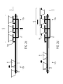
- Fig. 1 shows a schematic plan view of a packaging system 1 with a continuously running chain feeder 2, a Trayzu exchange invention 3 and a merely indicated Schalenversch employmaschine 4, which has a sealing station 5.
- the chain feed 2 comprises a link chain 6 with slide elements 7, by means of which product-filled trays 8 are provided in a transport direction T of the tray feed 3.
- a drive 9 is designed as a servomotor and attached to the end of the chain feeder 2 in order to drive the link chain 6 at a constant speed.
- a sensor 10 provided at the end of the chain feeder 2 is configured to detect the presence of a tray 8 just prior to transfer to the tray feeder 3 and to forward the information thereon to a controller 11.
- the tray feeder 3 is shown in an embodiment with a first 12a and a second pull chain 12b, each comprising two transport chains 13a, 13b, to each of which three slide elements 14a, 14b are mounted.
- the first pull chain 12a comprises two conveyor chains 13a, 13a, one of which is located on the right and one on the left of the track S taken from the trays 8 along the tray feeder 3. These two transport chains 13a are interconnected by means of slide elements 14a.
- the three slider elements 14a define a portion of the first pull chain 12a, which is designed to receive and transport a train, ie a group of three trays 8.
- the second pull chain 12b comprises two transport chains 13b, of which one right and one left of the track S taken by the trays are arranged along the tray feed 3.
- the two transport chains 13b of the second Pull chain 12b are interconnected by three slide elements 14b.
- the three slider elements 14b define a portion of the second pull chain 12b which can receive and transport a train, ie a group of three trays in this case.
- the two pull chains 12a, 12b are thus "superimposed" in the sense in the sense, as taken by the trays 8 along the Trayzu Installation 8 way, ie the track S, both of the slide elements 14a of the first pull chain 12a, as well as of the Slider elements 14b of the second pull chain 12b is swept over.
- the first pull chain 12a is driven by a first drive 15a and the second pull chain 12b by a second drive 15b at the downstream end of the tray feeder 3, preferably by means of servomotors.
- the trays 8 are moved along a common track S in the transporting direction T.
- the Fig. 2a shows a schematic side view of the chain feeder 2, which moves the trays 8 continuously or equidistantly with a constant speed in the transport direction T downstream of the Trayzu Entry 3.
- the sensor 10 which may be implemented in the simplest form as a light barrier, the presence of a tray 8 for transferring to the Trayzu Entry 3 is detected.
- the tray 8 to be transferred is pushed over the slide element 7 of the link chain 6 onto a transport support 16 of the tray feed 3 and subsequently transported further by a slide element 14a of the first pull chain 12a.
- the first pull chain 12a waits until the chain feed 2, which continues to run continuously, provides a next tray 8 for transfer. Over a distance D between two successive slide elements 14a of the first pull chain 12a, the position of the trays 8 relative to each other and a total of one group G of three trays 8 in this example are defined. In the Fig. 2a also the slide elements 14b of the second pull chain 12b are shown schematically by dashed lines.
- the second pull chain 12b is on the way to the beginning of the Trayzu Entry 3 to take a next tray 8 as the first of a new group G of the chain feeder 2, without the chain feeder 2 must interrupt their continuous operation.
- the Arrows indicate the movement of link chain 6, first 12a and second pull chain 12b.
- Fig. 2c shows a lifting device 17 which is configured to raise the group G of trays 8 from the transport support 16 so far that the bottom of the trays 8 is located above the slide elements 14a.
- trays 8 are shown during their transfer from the Trayzu arrangement 3 in the sealing station 5 of the Schalenversch employmaschine 4 by means of a gripper system 18 shown only schematically. Meanwhile, the second pull chain 12b receives further trays 8. In the sealing station 5, the trays are evacuated and / or gassed or hermetically sealed only with a lid film.
- a variant embodiment is also conceivable in which a loading station is provided along the transport path of the tray feed 3 after the takeover of the trays 8 and before the removal position at the end of the tray feed 3.
- a further third pull chain is provided so that a group G of trays 8, for example, moves under a filler for filling with liquid or pasty product and the trays 8 at the same time or successively supplemented by this additional product and can be completed with it before the subsequent sealing station 5 is evacuated and / or fumigated or sealed airtight only with a lid film.
- the chain feeder 2 can instead of being designed as a link chain 6 with slide elements 7 as a link chain belt.
Landscapes
- Engineering & Computer Science (AREA)
- Mechanical Engineering (AREA)
- Chemical & Material Sciences (AREA)
- Dispersion Chemistry (AREA)
- Microelectronics & Electronic Packaging (AREA)
- Closing Of Containers (AREA)
Abstract
Die Erfindung betrifft eine Schalenverschließmaschine mit Trayzuführung (3) zur Aufnahme von Trays (8) von einer kontinuierlich laufenden Kettenzuführung (2) und zum Gruppieren dieser Trays (8), wobei die Trayzuführung (3) wenigstens zwei Zugketten (12a, 12b) aufweist. Eine Gruppe G von Trays (8) wird anschließend mittels eines Greifersystems (17) an eine Siegelstation (5) einer Schalenverschließmaschine (4) übergebenThe invention relates to a tray closing machine with tray feed (3) for receiving trays (8) from a continuously running chain feeder (2) and for grouping these trays (8), the tray feeder (3) having at least two pull chains (12a, 12b). A group G of trays (8) is then transferred by means of a gripper system (17) to a sealing station (5) of a tray sealing machine (4)
Description
Die Erfindung bezieht sich auf eine Schalenverschließmaschine, auch Traysealer genannt, gemäß dem Oberbegriff des Anspruchs 1.The invention relates to a tray sealing machine, also called tray sealer, according to the preamble of claim 1.
Aus der
Eine Ausführung einer kontinuierlich betriebenen Trayzuführung ist in der noch nicht veröffentlichten
Aufgabe der vorliegenden Erfindung ist es, eine Schalenverschließmaschine mit einer Trayzuführung für eine kontinuierlich betriebene Kettenzuführung für eine Schalenverschließmaschine und ein Verfahren zum Betrieb einer solchen Trayzuführung zur Verfügung zu stellen, die die oben genannten Nachteile nicht mehr aufweist, so dass insbesondere eine Lücke zwischen Gruppen von Trays auf einer Kettenzuführung entfallen kann.The object of the present invention is to provide a tray sealing machine with a tray feeder for a continuously operated chain feeder for a tray closing machine and a method for operating such a tray feeder, which no longer has the disadvantages mentioned above, so that in particular a gap between groups of Trays on a chain feeder can be omitted.
Diese Aufgabe wird gelöst durch eine Schalenverschließmaschine mit den Merkmalen des Anspruchs 1 bzw. durch ein Verfahren zum Betrieb einer Verpackungsanlage mit einer solchen Trayzuführung mit den Merkmalen des Anspruchs 10. Vorteilhafte Weiterbildungen der Erfindung sind in den Unteransprüchen angegeben.This object is achieved by a tray sealing machine with the features of claim 1 or by a method for operating a packaging system with such Trayzuführung with the features of
Die erfindungsgemäße Trayzuführung zum Aufnehmen von Trays von einer kontinuierlich laufenden Kettenzuführung und zum Gruppieren dieser Trays ist dadurch gekennzeichnet, dass die Trayzuführung wenigstens eine erste und eine zweite Zugkette mit jeweils einem eigenen Antrieb und eigenen Schieberelementen aufweist. Somit sind die Zugketten getrennt voneinander betreibbar und ermöglichen ein Aufnehmen einer Gruppe von Trays von einer Kettenzuführung mittels einer ersten Zugkette und gleichzeitig ein davon unabhängiges Positionieren der Gruppe von Trays zum Weitertransport in eine Siegelstation durch ein Greifersystem einer Schalenverschließmaschine mittels einer zweiten Zugkette. Die an den Zugketten angebrachten Schieberelemente transportieren die Trays schiebend. Es entsteht der Vorteil, dass eine kontinuierlich laufende Kettenzuführung keine Lücke, wie sie aus dem genannten Stand der Technik bekannt ist, mehr aufweisen muss und auch nicht vorhandene bzw. fehlende Trays zu keinem Stillstand mehr und damit zu einer Reduzierung von Ausfallzeiten führen.The tray feed according to the invention for receiving trays from a continuously running chain feed and for grouping these trays is characterized in that the tray feed has at least one first and one second pull chain, each with its own drive and slide elements. Thus, the pull chains are operable separately from each other and allow a group of trays to be picked up from a chain feeder by means of a first pull chain and at the same time independently positioning the group of trays for further transport into a sealing station by a gripper system of a tray closing machine by means of a second pull chain. The slide elements attached to the draw chains transport the trays. The advantage arises that a continuously running chain feeder does not have a gap, as is known from the cited prior art, must have more and also non-existent or missing trays to no more standstill and thus lead to a reduction of downtime.
Eine Zugkette kann als eine einzelne Kette mit einseitig angebrachten Schieberelementen vorgesehen sein. Die Kette kann als eine Gliederkette, ein Zahnriemen oder dergleichen ausgeführt sein. Die Zugkette kann auch zwei parallel und gemeinsam angetriebene Ketten oder Riemen aufweisen, wobei die Schieberelemente dabei zwischen den Ketten angeordnet und mit ihren Enden an jeweils einer der zwei Ketten angebracht sind.A pull chain can be provided as a single chain with single-sided slide elements. The chain may be designed as a link chain, a toothed belt or the like. The pull chain can also have two parallel and jointly driven chains or belts, wherein the slider elements are arranged between the chains and attached with their ends to each one of the two chains.
Der Begriff "Zugkette" (englisch: train chain) bedeutet im Kontext der Erfindung, dass eine solche Kette einen "Zug" von Schalen transportieren kann, d.h. eine Gruppe von Schalen mit einer bestimmten Anzahl, die hintereinander in Transportrichtung angeordnet sind. Die Länge des Zuges, also die Anzahl der hintereinander in einer Gruppe angeordneten Schalen, kann bspw. durch die Anzahl der mit der Zugkette verbundenen Schiebeelemente vorgegeben sein. Durch das Vorsehen von wenigstens zwei Zugketten mit jeweils einem eigenen Antrieb ermöglicht es die Erfindung, die Schalen aus einem kontinuierlichen Zustrom abzunehmen und einzelne "Züge" mit höherer Geschwindigkeit vom Übergabepunkt abfahren zu lassen, sobald sie komplettiert sind.The term "train chain" in the context of the invention means that such a chain can carry a "train" of trays, i. a group of shells with a certain number, which are arranged one behind the other in the transport direction. The length of the train, that is to say the number of shells arranged one behind the other in a group, can be predetermined, for example, by the number of sliding elements connected to the pull chain. By providing at least two pull chains each with its own drive, the invention makes it possible to remove the shells from a continuous influx and to let individual "trains" leave the transfer point at a higher speed once they have been completed.
Sobald eine Zugkette am Ende der Trayzuführung von den von ihr transportierten Schalen befreit ist, kann sie ggf. mit hoher Geschwindigkeit wieder an den Übergabepunkt am Anfang der Trayzuführung zurückgefahren werden. Dort trifft die Zugkette vorzugsweise so rechtzeitig ein, dass sie auch ohne eine Verlangsamung des Zustroms von Schalen die nach dem Komplettieren einer anderen Zugkette übergebene, erste Schale wieder übernehmen kann.As soon as a pull chain at the end of the tray feed is freed from the trays it is transporting, it may possibly be returned to the transfer point at the beginning of the tray feed at high speed. There, the pull chain preferably arrives in time so that it can take over again without a slowing down of the influx of shells handed over the completion of another train, first shell again.
Bevorzugt sind die Zugketten dazu konfiguriert, eine einzige Gruppe von Trays zu transportieren, wobei die Abstände der einzelnen Trays einer Gruppe zueinander bei der Übernahme der Trays von der Kettenzuführung auf die Zugkette gebildet werden. Die Anzahl der Gruppe von Trays entspricht der Anzahl von Trays, die mit einer Transportbewegung durch das Greifersystem der Schalenverschließmaschine von der Zugkette und damit von der Trayzuführung abgenommen und in eine Siegelstation übergeben werden.Preferably, the pull chains are configured to transport a single group of trays, with the distances of the individual trays of a group from one another being formed when the trays are taken over from the chain feed to the pull chain. The number of the group of trays corresponds to the number of trays which are removed with a transport movement by the gripper system of the tray sealing machine from the pull chain and thus from the Trayzuführung and transferred to a sealing station.
Alternativ sind die Zugketten dazu konfiguriert, entlang ihres Verlaufs an mehreren Abschnitten jeweils eine Gruppe von Trays transportieren zu können, wobei die Gruppen jeweils eine gleiche Anzahl von Trays aufweisen. Besonders vorteilhaft ist dies bei einer hohen Anzahl von Trays in einer Gruppe, längeren Transportstrecken oder bei einem weiteren Füllen der Trays mit einem beispielsweisen flüssigen oder pastösen Produkt auf der Trayzuführung selbst, wobei im Falle des weiteren Füllens im Bereich der Trayzuführung wenigstens eine dritte Zugkette vorgesehen sein sollte.Alternatively, the train chains are configured to be able to transport a group of trays at several sections along their course, the groups each having an equal number of trays. This is particularly advantageous for a large number of trays in a group, longer transport distances or further filling of the trays with an example liquid or pasty product on the Trayzuführung itself, wherein provided in the case of further filling in the tray delivery at least a third pull chain should be.
Allgemein umfasst hier die Zugkette also mindestens einen Abschnitt, auf dem ein Zug, bzw. eine Gruppe von Trays aufgenommen werden kann, sowie übrige, freie Abschnitte. Sobald ein vollständiger Zug von Schalen von der Zugkette abgenommen wurde, kann diese Zugkette mit ggf. erhöhter Geschwindigkeit so vorwärts bewegt werden, dass am Anfang der Trayzuführung wieder ein Abschnitt zur Aufnahme eines neuen Zuges von Schalen bereitgestellt wird. Bei sehr langen Förderstrecken der Trayzuführung kann es vorkommen, dass die dafür erforderlichen Geschwindigkeiten der Zugketten extrem hoch würden, um rechtzeitig wieder am Ausgangspunkt einen Abschnitt zur Aufnahme eines neuen Zuges bereitstellen zu können. In diesem Fall kann es vorteilhaft sein, wenn die Zugkette entlang ihres Verlaufs mehrere Abschnitte zur Aufnahme jeweils eines Zuges von Trays aufweist. Denn dann muss die Zugkette nur jeweils um eine so kurze Distanz vorwärts bewegt werden, dass am Ausgangspunkt der Trayzuführung der nächste freie Abschnitt zur Aufnahme von Trays bereitgestellt wird.In general, the pull chain here thus comprises at least one section on which a train or a group of trays can be received, as well as remaining, free sections. Once a complete train of trays has been removed from the drawstring, this traction chain can be moved forward with possibly increased speed so that at the beginning of Trayzuführung again a section for receiving a new train of trays is provided. In the case of very long conveyor lines of the tray feed, it may happen that the speeds required for the pull chains would become extremely high in order to be able to provide a section for picking up a new train in good time at the starting point. In this case, it may be advantageous if the pull chain along its course has several sections for receiving a train of trays. Because then the pull chain only has to be moved forward by such a short distance that the next free section for receiving trays is provided at the starting point of the tray feed.
Die Zugketten sind bevorzugt entlang einer gemeinsamen Spur überlagert vorgesehen, um die Gruppen von Trays entlang der gemeinsamen Spur nachfolgend zu transportieren. Die Spur ist dabei der Weg, entlang dessen die Trays in Transportrichtung transportiert werden. Dass die Zugketten entlang einer gemeinsamen Spur "überlagert" vorgesehen sind, bedeutet, dass der Weg, entlang dessen sich die Trays in Transportrichtung bewegen (bspw. in direkter Verlängerung eines entsprechenden Transportweges entlang der Kettenzuführung) von den Schieberelementen sämtlicher Zugketten überstrichen wird. Bspw. kann dies erreicht werden, indem jede Zugkette eine erste und eine zweite Transportkette aufweist, von denen eine in Förderrichtung rechts und die andere in Förderrichtung links seitlich neben dem von den Trays genommenen Weg angeordnet ist. Die beiden einer gemeinsamen Zugkette zugeordneten Transportketten können dabei insbesondere durch Schiebeelemente miteinander verbunden sein.The train chains are preferably superimposed along a common track to subsequently transport the groups of trays along the common track. The track is the path along which the trays are transported in the transport direction. The fact that the tension chains are provided "superimposed" along a common track means that the path along which the trays move in the transport direction (for example in direct extension of a corresponding transport path along the chain feed) is swept by the slide elements of all tension chains. For example. This can be achieved by each train chain having a first and a second transport chain, one of which is arranged in the conveying direction right and the other in the conveying direction on the left side next to the path taken by the trays. The two transport chains assigned to a common pull chain can be connected to one another in particular by sliding elements.
In einer vorteilhaften Ausführung ist eine Anhebevorrichtung vorgesehen, um die Trays bereitzustellen zum Weitertransport mittels eines Greifersystems einer Schalenverschließmaschine. Die Anhebevorrichtung überbrückt die Schieberelemente der Zugkette, damit die Gruppe von Trays barrierefrei mittels des Greifersystems in die Siegelstation der Schalenverschließmaschine transportiert werden kann.In an advantageous embodiment, a lifting device is provided to provide the trays for onward transport by means of a gripper system of a tray sealing machine. The lifting device bridges the slider elements of the pull chain so that the group of trays can be transported barrier-free by means of the gripper system into the sealing station of the tray closing machine.
Vorzugsweise umfasst eine Schalenverschließmaschine die erfindungsgemäße Trayzuführung, um die Leistung zu steigern bzw. Stillstandszeiten zu reduzieren.Preferably, a tray sealing machine comprises the tray feed according to the invention in order to increase the power or to reduce downtimes.
Die Gruppe von Trays weist bevorzugt eine Anzahl auf, die gleich der Anzahl von Trays ist, die mittels des Greifersystems von der Trayzuführung übernommen und in die Siegelstation der Schalenverschließmaschine übergeben werden, da ein beispielsweise fehlender Tray bei der Bearbeitung in der Siegelstation zu Problemen führen kann, beispielsweise durch ein Verkleben einer Deckelfolie am Siegelwerkzeugunterteil im Bereich des fehlenden Trays.The group of trays preferably has a number equal to the number of trays which are picked up by the gripper system from the tray feeder and transferred to the sealing station of the tray seaming machine, since an absent tray, for example, can cause problems in processing in the sealing station , For example, by gluing a lid film on the sealing tool lower part in the region of the missing tray.
Vorzugsweise ist eine in einer Transportrichtung stromaufwärts vor der Trayzuführung angeordnete, kontinuierlich laufende Kettenzuführung vorgesehen, von der die Trayzuführung Trays aufnimmt und dabei einen definierten Abstand zwischen den aufeinanderfolgenden Trays mittels der Schieberelemente der Zugketten erzeugt. Dabei sind die Abstände der Schieberelemente für eine Gruppe von Trays zueinander gleich und stehen in Relation mit Greifern des Greifersystems.Preferably, in a transport direction upstream of the Trayzuführung arranged continuously running chain feeder is provided, from which the Trayzuführung receives trays and thereby generates a defined distance between the successive trays by means of the slide elements of the tension chains. The distances of the slide elements for a group of trays are the same and are in relation to grippers of the gripper system.
Vorzugsweise ist am in Transportrichtung stromabwärts befindlichen Ende der Kettenzuführung ein Sensor vorgesehen, um das Vorhandensein eines Trays vor der Übergabe an die Trayzuführung festzustellen. Dies stellt sicher, dass eine Gruppe auf einer Zugkette immer die notwendige Anzahl von Trays aufweist und kein Tray vor oder zwischen den Schieberelementen fehlt. Somit führen fehlende Trays auf der Kettenzuführung nicht zu Problemen oder Stillstandszeiten der Trayzuführung bzw. der Schalenverschließmaschine, dies erhöht die Prozesssicherheit.Preferably, a sensor is provided at the downstream end of the chain feeder in the direction of transport to detect the presence of a tray prior to transfer to the tray feeder. This ensures that a group on a pull chain always has the necessary number of trays and no tray is missing before or between the slider elements. Thus missing trays on the chain feeder do not lead to problems or downtimes of the tray feed or the tray sealing machine, this increases the process reliability.
Die Schalenverschließmaschine umfasst bevorzugt eine Steuerung, um den Sensor auszuwerten und die Trayzuführung zu steuern. Die Auswertung des Sensors stellt sicher, dass eine Gruppe immer ihre vorgesehene Gesamtzahl von Trays aufweist. Die Steuerung der Trayzuführung erfolgt über die Ansteuerung der einzelnen Antriebe der Zugketten, vorzugsweise Servomotoren, um die Trays mit geringen Beschleunigungsänderungen zu bewegen. Dies ermöglicht wiederum eine Erhöhung der Leistung der Verpackungsmaschine bei flüssigen oder pastösen Produkten.The tray sealing machine preferably includes a controller for evaluating the sensor and controlling the tray feed. The evaluation of the sensor ensures that a group always has its intended total number of trays. The control of the Trayzuführung via the control of the individual drives of the train chains, preferably servomotors to move the trays with small changes in acceleration. This in turn allows an increase in the performance of the packaging machine in liquid or pasty products.
Vorzugsweise umfasst die Schalenverschließmaschine eine Steuerung, mittels derer die Zugketten der Trayzuführung steuerbar sind, um unabhängig voneinander mittels der ersten Zugkette die Trays, die stromaufwärts von der Kettenzuführung bereitgestellt werden, aufzunehmen und mittels der zweiten Zugkette die Gruppe von Trays an eine Entnahmeposition zur Übernahme durch das stromabwärts vorgesehene Greifersystem zu transportieren. Sobald das Greifersystem die Trays übernommen hat und die Anhebevorrichtung in ihre Grundstellung abgesenkt wurde, fährt die zweite Zugkette die Schieberelemente vorzugsweise in kürzester Zeit zum vorderen Ende der Trayzuführung, um wiederholt ein neu ankommendes Tray von der Kettenzuführung aufzunehmen, nachdem das zuvor letzte Tray von der anderen Zugkette aufgenommen und die komplettierte Gruppe weitertransportiert wurde.Preferably, the tray closing machine comprises a controller by means of which the draw chains of the tray feed are controllable to receive independently of each other by means of the first pull chain the trays provided upstream of the chain feeder and by means of the second pull chain the group of trays to a removal position for acceptance by to transport the gripper system provided downstream. Once the gripper system has taken over the trays and the lifting device has been lowered to its normal position, the second pull chain preferably moves the slider elements in the shortest possible time to the front end of the Trayzuführung to repeatedly receive a new incoming tray from the chain feeder after the last last tray of the other train chain was added and the completed group was transported.
Das erfindungsgemäße Verfahren zum Betrieb einer Verpackungsanlage, die eine Schalenverschließmaschine mit der zuvor beschriebenen erfindungsgemäßen Trayzuführung und eine kontinuierlich laufende Kettenzuführung umfasst, zeichnet sich dadurch aus, dass die Trays von der Kettenzuführung an die erste Transportkette der Trayzuführung einzeln nacheinander übergeben werden, bis eine Gruppe der ersten Zugkette komplettiert ist.The inventive method for operating a packaging system comprising a tray sealing machine with the above-described invention Trayzuführung and a continuously running chain feeder is characterized in that the trays are transferred from the chain feeder to the first transport chain of Trayzuführung one after the other until a group of first pull chain is completed.
Im Folgenden wird ein vorteilhaftes Ausführungsbeispiel der Erfindung anhand einer Zeichnung näher erläutert. Im Einzelnen zeigen:
- Fig. 1
- in einer schematischen Draufsicht eine Verpackungsanlage mit einer erfindungsgemäßen Trayzuführung,
- Fig. 2a
- die erfindungsgemäße Trayzuführung mit einer Kettenzuführung in einer schematischen Seitenansicht bei der Übernahme von Trays,
- Fig. 2b
- die Trayzuführung mit einer Gruppe von Trays in einer Entnahmeposition,
- Fig. 2c
- die Trayzuführung mit aktivierter Anhebevorrichtung und
- Fig. 2d
- die Trayzuführung während einer Übernahme der Trays durch ein Greifersystem.
- Fig. 1
- in a schematic plan view of a packaging system with a Trayzuführung invention,
- Fig. 2a
- the tray feed according to the invention with a chain feed in a schematic side view when taking over trays,
- Fig. 2b
- the tray feed with a group of trays in a picking position,
- Fig. 2c
- the tray feeder with activated lifting device and
- Fig. 2d
- the Trayzuführung during a takeover of the trays by a gripper system.
Gleiche Komponenten sind in den Figuren durchgängig mit gleichen Bezugszeichen versehen.The same components are provided throughout the figures with the same reference numerals.
In der
Analog dazu umfasst die zweite Zugkette 12b zwei Transportketten 13b, von denen eine rechts und eine links der von den Trays genommenen Spur S entlang der Trayzuführung 3 angeordnet ist. Die beiden Transportketten 13b der zweiten Zugkette 12b sind durch drei Schieberelemente 14b miteinander verbunden. Die drei Schieberelemente 14b definieren einen Abschnitt der zweiten Zugkette 12b, der einen Zug, d.h. eine Gruppe von in diesem Fall drei Trays aufnehmen und transportieren kann. Die beiden Zugketten 12a, 12b sind damit in diesem Ausführungsbeispiel in dem Sinne "überlagert", als der von den Trays 8 entlang der Trayzuführung 8 genommene Weg, d.h. die Spur S, sowohl von den Schieberelementen 14a der ersten Zugkette 12a, als auch von den Schieberelementen 14b der zweiten Zugkette 12b überstrichen wird.Analogously, the
Die erste Zugkette 12a wird von einem ersten Antrieb 15a und die zweite Zugkette 12b von einem zweiten Antrieb 15b am stromabwärts gelegenen Ende der Trayzuführung 3 angetrieben, vorzugsweise mittels Servomotoren. Die Trays 8 werden entlang einer gemeinsamen Spur S in der Transportrichtung T bewegt.The
Anhand der
Im weiteren Verlauf wird auf die Darstellung der Kettenzuführung 2 verzichtet und in
In
Es ist auch eine Ausführungsvariante denkbar, bei der entlang der Transportstrecke der Trayzuführung 3 eine Beladestation nach der Übernahme der Trays 8 und vor der Entnahmeposition am Ende der Trayzuführung 3 vorgesehen ist. In diesem Fall ist eine weitere dritte Zugkette vorgesehen, damit eine Gruppe G von Trays 8 beispielsweise unter einen Füller zum Befüllen mit flüssigem oder pastösen Produkt bewegt und die Trays 8 gleichzeitig oder nacheinander durch dieses weitere Produkt ergänzt und damit komplettiert werden können, bevor sie in der nachfolgenden Siegelstation 5 evakuiert und/oder begast oder lediglich mit einer Deckelfolie luftdicht versiegelt werden.A variant embodiment is also conceivable in which a loading station is provided along the transport path of the
Die Kettenzuführung 2 kann statt als Gliederkette 6 mit Schieberelementen 7 auch als Gliederkettenband ausgeführt sein.The
Claims (12)
von Trays (8) von einer kontinuierlich laufenden Kettenzuführung (2) und zum Gruppieren dieser Trays (8), dadurch gekennzeichnet, dass die Trayzuführung (3) wenigstens eine erste (12a) und eine zweite Zugkette (12b) mit jeweils einem eigenen Antrieb (15a, 15b) und eigenen Schieberelementen (14a, 14b), aufweist.Tray closing machine (4) with a tray feeder (3) for receiving
of trays (8) from a continuously running chain feeder (2) and for grouping these trays (8), characterized in that the tray feeder (3) has at least a first (12a) and a second pull chain (12b), each with its own drive ( 15a, 15b) and own slide elements (14a, 14b).
Priority Applications (2)
| Application Number | Priority Date | Filing Date | Title |
|---|---|---|---|
| EP13173591.2A EP2818421A1 (en) | 2013-06-25 | 2013-06-25 | Tray closing machine with tray supply and method for a packaging system |
| US14/276,842 US9327852B2 (en) | 2013-06-25 | 2014-05-13 | Tray sealer with a tray feeder and a method for a packaging facility |
Applications Claiming Priority (1)
| Application Number | Priority Date | Filing Date | Title |
|---|---|---|---|
| EP13173591.2A EP2818421A1 (en) | 2013-06-25 | 2013-06-25 | Tray closing machine with tray supply and method for a packaging system |
Publications (1)
| Publication Number | Publication Date |
|---|---|
| EP2818421A1 true EP2818421A1 (en) | 2014-12-31 |
Family
ID=48745691
Family Applications (1)
| Application Number | Title | Priority Date | Filing Date |
|---|---|---|---|
| EP13173591.2A Withdrawn EP2818421A1 (en) | 2013-06-25 | 2013-06-25 | Tray closing machine with tray supply and method for a packaging system |
Country Status (2)
| Country | Link |
|---|---|
| US (1) | US9327852B2 (en) |
| EP (1) | EP2818421A1 (en) |
Families Citing this family (9)
| Publication number | Priority date | Publication date | Assignee | Title |
|---|---|---|---|---|
| DE102016204193A1 (en) * | 2016-03-15 | 2017-09-21 | Multivac Sepp Haggenmüller Se & Co. Kg | Transport device for trays |
| CN108312590B (en) * | 2018-01-16 | 2023-08-08 | 湖北华强科技股份有限公司 | Production line of breathing mask assembly |
| DE102018213213B4 (en) * | 2018-08-07 | 2020-03-12 | Multivac Sepp Haggenmüller Se & Co. Kg | Method for operating a tray sealing machine |
| DE102019206345A1 (en) * | 2019-05-03 | 2020-11-05 | Multivac Sepp Haggenmüller Se & Co. Kg | TRAY SEALING MACHINE AND METHOD FOR OPERATING A GRIPPER DEVICE ON THE TRAY SEALING MACHINE |
| CN110077798A (en) * | 2019-05-31 | 2019-08-02 | 海安交睿机器人科技有限公司 | A kind of straight line material library suitable for transformer core automatic overlapping and assembling |
| DE102019215451A1 (en) * | 2019-10-09 | 2021-04-15 | Multivac Sepp Haggenmüller Se & Co. Kg | Tray sealing machine with two-lane conveyor arrangement and conveyor method |
| CN113443411B (en) * | 2020-03-25 | 2022-09-16 | 盟立自动化股份有限公司 | Pallet conveying equipment and conveying device thereof |
| WO2022023740A1 (en) * | 2020-07-28 | 2022-02-03 | Packaging Automation Limited | Improvements in and relating to packaging apparatus |
| EP3945038B1 (en) * | 2020-07-28 | 2023-11-29 | Packaging Automation Limited | Improvements in and relating to packaging apparatus |
Citations (8)
| Publication number | Priority date | Publication date | Assignee | Title |
|---|---|---|---|---|
| EP0594917A1 (en) * | 1991-04-04 | 1994-05-04 | Pamag Ag | Method for taking over continuously delivered products from a production device and for delivering discontinuously a number of those products in a delivering station |
| EP0695703A1 (en) * | 1994-08-04 | 1996-02-07 | CAMA 1 SpA | Apparatus for conveying products in groups |
| US6019213A (en) * | 1995-06-19 | 2000-02-01 | Gerhard Schubert Gmbh | Grouping and buffer apparatus |
| EP1200675A1 (en) | 1999-08-05 | 2002-05-02 | Ciba SC Holding AG | Use of whitening pigments for whitening paper coating compositions |
| EP1298079A1 (en) * | 2001-09-26 | 2003-04-02 | Ishida Co., Ltd. | Conveyance apparatus and boxing system |
| DE69923892T2 (en) * | 1998-08-12 | 2006-04-06 | Aries Packaging | Apparatus for forming groups of juxtaposed articles and equipment with such a device |
| DE102008030510A1 (en) | 2008-06-27 | 2010-01-14 | Multivac Sepp Haggenmüller Gmbh & Co. Kg | Packaging machine with a gripper system |
| US20110072764A1 (en) * | 2009-09-30 | 2011-03-31 | Ross Industries, Inc. | Method and apparatus for sealing containers |
Family Cites Families (27)
| Publication number | Priority date | Publication date | Assignee | Title |
|---|---|---|---|---|
| IT984820B (en) * | 1973-04-26 | 1974-11-20 | Mori C | AUTOMATIC MACHINE CAPABLE OF ORDERLY PREPARING AFFIAN CANDLES IN PREFIXABLE NUMBER OF BAGS OR PUSHES OR OTHER OBJECTS OF A GEOMETRIC SHAPE NOT DEFINED OR MODIFIABLE |
| NZ184743A (en) * | 1976-08-06 | 1980-09-12 | Monier Concrete Ind | Stacking tiles on high speed conveyor |
| US4186544A (en) * | 1978-05-25 | 1980-02-05 | Baker Perkins Holding Limited | Wrapping machines |
| US4214419A (en) * | 1978-10-02 | 1980-07-29 | Wheaton Industries | Collating and shrink wrap packaging apparatus |
| GB2100212B (en) * | 1981-05-14 | 1984-06-27 | Baker Perkins Holdings Plc | Apparatus for collating articles to be wrapped into batches |
| US4525977A (en) * | 1983-05-13 | 1985-07-02 | Doboy Packaging Machinery, Inc. | Wrapping machine and method |
| US4574566A (en) * | 1985-01-14 | 1986-03-11 | Doboy Packaging Machinery, Inc. | Wrapping machine and method |
| SE8603961L (en) * | 1986-09-19 | 1988-03-20 | Volvo Ab | DEVICE BY A TRANSPORTOR |
| DE3705561C1 (en) * | 1987-02-21 | 1988-02-25 | Mueller Georg Nuernberg | Conveyor device |
| US4768642A (en) * | 1987-06-16 | 1988-09-06 | Kimberly-Clark Corporation | Multiple conveyors with overlapping material handling device paths |
| US5044876A (en) * | 1990-05-02 | 1991-09-03 | Apv Crepaco, Inc. | Apparatus for forming and transferring groups of articles |
| DE9215186U1 (en) * | 1992-11-07 | 1993-12-02 | KRONES AG, 93073 Neutraubling | Transport device for vessels |
| US5419097A (en) * | 1993-11-18 | 1995-05-30 | World Class Packaging Systems, Inc. | Method and apparatus for packaging food |
| IT1269721B (en) * | 1994-05-06 | 1997-04-15 | Mondini G Spa | MACHINE FOR SEALING CONTAINERS THROUGH THE APPLICATION OF A COVERING PLATE |
| US5937620A (en) * | 1995-03-03 | 1999-08-17 | The Mead Corporation | Packaging machine for multi-packs |
| EP0883565B1 (en) * | 1996-02-23 | 2000-07-19 | Böwe Systec Ag | Conveyor and gathering system |
| IT1305379B1 (en) * | 1998-09-01 | 2001-05-04 | Casmatic Spa | APPARATUS FOR THE AUTOMATIC ADJUSTMENT OF THE LENGTH OF THE CONTAINERS OF THE CONVEYOR OF PACKAGING AND PACKING MACHINES |
| US6293544B1 (en) * | 1999-12-22 | 2001-09-25 | Xerox Corporation | Apparatus and method for registering and conveying a compiled set of sheets |
| DE10048007A1 (en) * | 2000-09-26 | 2002-04-11 | Iwk Verpackungstechnik Gmbh | Method and device for transferring a product in a packaging machine |
| ITBO20000685A1 (en) * | 2000-11-23 | 2002-05-23 | Gianluigi Gamberini | TOWING DEVICE FOR MACHINES FOR PACKAGING ARTICLES IN ROLLS AND SIMILAR |
| JP3974409B2 (en) * | 2002-01-22 | 2007-09-12 | 株式会社イシダ | Conveying device and boxing device provided with the same |
| EP1389592A1 (en) * | 2002-08-13 | 2004-02-18 | Innopack S.r.l. | A device for conveying stacks of sheets of paper or the like |
| US20050098942A1 (en) * | 2003-11-07 | 2005-05-12 | Heidelberger Druckmaschinen Ag | Pin conveyor for printed sheet material and transfer unit |
| US7588239B2 (en) * | 2005-12-14 | 2009-09-15 | Pitney Bowes Inc. | Transport and alignment system |
| DE102006049801A1 (en) * | 2006-10-23 | 2008-04-24 | Iwk Verpackungstechnik Gmbh | Product stack delivery controlling method for packaging machine, involves beginning delivery cycle in such manner that cell of conveyor adopts predetermined relative position relative to product stack at end of delivery cycle |
| DE102009049179B4 (en) * | 2009-10-13 | 2023-10-12 | Multivac Sepp Haggenmüller Se & Co. Kg | Method and packaging machine for packaging products |
| BR112013006603B1 (en) * | 2010-09-22 | 2020-06-23 | Bobst Mex Sa | TRANSPORT DEVICE FOR DISPLACING A SUCCESSION OF BEAMS AND MACHINING MACHINE |
-
2013
- 2013-06-25 EP EP13173591.2A patent/EP2818421A1/en not_active Withdrawn
-
2014
- 2014-05-13 US US14/276,842 patent/US9327852B2/en active Active
Patent Citations (8)
| Publication number | Priority date | Publication date | Assignee | Title |
|---|---|---|---|---|
| EP0594917A1 (en) * | 1991-04-04 | 1994-05-04 | Pamag Ag | Method for taking over continuously delivered products from a production device and for delivering discontinuously a number of those products in a delivering station |
| EP0695703A1 (en) * | 1994-08-04 | 1996-02-07 | CAMA 1 SpA | Apparatus for conveying products in groups |
| US6019213A (en) * | 1995-06-19 | 2000-02-01 | Gerhard Schubert Gmbh | Grouping and buffer apparatus |
| DE69923892T2 (en) * | 1998-08-12 | 2006-04-06 | Aries Packaging | Apparatus for forming groups of juxtaposed articles and equipment with such a device |
| EP1200675A1 (en) | 1999-08-05 | 2002-05-02 | Ciba SC Holding AG | Use of whitening pigments for whitening paper coating compositions |
| EP1298079A1 (en) * | 2001-09-26 | 2003-04-02 | Ishida Co., Ltd. | Conveyance apparatus and boxing system |
| DE102008030510A1 (en) | 2008-06-27 | 2010-01-14 | Multivac Sepp Haggenmüller Gmbh & Co. Kg | Packaging machine with a gripper system |
| US20110072764A1 (en) * | 2009-09-30 | 2011-03-31 | Ross Industries, Inc. | Method and apparatus for sealing containers |
Also Published As
| Publication number | Publication date |
|---|---|
| US20140374217A1 (en) | 2014-12-25 |
| US9327852B2 (en) | 2016-05-03 |
Similar Documents
| Publication | Publication Date | Title |
|---|---|---|
| EP2818421A1 (en) | Tray closing machine with tray supply and method for a packaging system | |
| EP2634100B1 (en) | Tray sealer and method for transporting trays | |
| EP2792623B1 (en) | Device and method for forming a predefined formation on a conveyor belt | |
| EP3210896B1 (en) | Method for operating a deep draw packaging machine | |
| EP2857333B1 (en) | Method and system for discharging beverage containers moving continuously in parallel rows on a horizontal conveyor | |
| EP2921436B1 (en) | Tube body transfer system, tube body production device and tube body transfer method | |
| EP2799349A1 (en) | Method for grouping articles in article bars and grouping device and packaging machine comprising one such and control device for product holding device | |
| EP2799348B1 (en) | Method for grouping articles in article bars and grouping device and packaging machine comprising same | |
| EP3003874B1 (en) | Method and device for producing packaged units in a tubular bag machine | |
| DE3237374A1 (en) | METHOD AND DEVICE FOR AUTOMATICALLY CHANGING REELS WITH BAND-SHAPED MATERIAL, ESPECIALLY IN PACKAGING MACHINES | |
| DE102016102170A1 (en) | Method and device for grouping product blanks | |
| DE69214122T2 (en) | METHOD AND SYSTEM FOR LINING ITEMS | |
| DE102013106187A1 (en) | Device and method for conveying, handling, packaging and / or palletizing of piece goods, packaged goods and / or containers | |
| EP3860937A1 (en) | Device and method for transporting a plurality of articles | |
| WO2007124958A1 (en) | Feeder for a tray sealer | |
| EP3089915B1 (en) | Device and method for portioning a flow of individual products | |
| EP2919732B1 (en) | Installation for the production of packed product stacks, especially of hygienic products | |
| WO2006111142A1 (en) | Packaging machine | |
| DE102008048831A1 (en) | Conveying device for packaging machine, has buffer conveyor, on which containers are conveyed, and collecting conveyor, through which containers are brought in predetermined distance to each other | |
| EP3632805A1 (en) | Device and method for stacking and packaging small-sized products | |
| EP2712815B1 (en) | Jacket closing machine | |
| DE19822837C1 (en) | Regulating method for timing of delivery of goods to be packed in running packing machine | |
| EP3023337B1 (en) | Method for controlling a folding box glueing machine with a subsequent device for packing | |
| DE69919477T2 (en) | Method and machine for packaging a group of articles | |
| EP3693299B1 (en) | Device for continuously conveying material and method for continuously conveying material |
Legal Events
| Date | Code | Title | Description |
|---|---|---|---|
| PUAI | Public reference made under article 153(3) epc to a published international application that has entered the european phase |
Free format text: ORIGINAL CODE: 0009012 |
|
| 17P | Request for examination filed |
Effective date: 20130625 |
|
| AK | Designated contracting states |
Kind code of ref document: A1 Designated state(s): AL AT BE BG CH CY CZ DE DK EE ES FI FR GB GR HR HU IE IS IT LI LT LU LV MC MK MT NL NO PL PT RO RS SE SI SK SM TR |
|
| AX | Request for extension of the european patent |
Extension state: BA ME |
|
| STAA | Information on the status of an ep patent application or granted ep patent |
Free format text: STATUS: THE APPLICATION IS DEEMED TO BE WITHDRAWN |
|
| 18D | Application deemed to be withdrawn |
Effective date: 20150701 |