EP3208405A1 - Dispositif et procédé de montage de constructions en forme de tours à partir d'éléments préfabriqués - Google Patents
Dispositif et procédé de montage de constructions en forme de tours à partir d'éléments préfabriqués Download PDFInfo
- Publication number
- EP3208405A1 EP3208405A1 EP16156324.2A EP16156324A EP3208405A1 EP 3208405 A1 EP3208405 A1 EP 3208405A1 EP 16156324 A EP16156324 A EP 16156324A EP 3208405 A1 EP3208405 A1 EP 3208405A1
- Authority
- EP
- European Patent Office
- Prior art keywords
- tower
- level
- construction
- crane
- stump
- Prior art date
- Legal status (The legal status is an assumption and is not a legal conclusion. Google has not performed a legal analysis and makes no representation as to the accuracy of the status listed.)
- Granted
Links
- 238000000034 method Methods 0.000 title claims abstract description 34
- 238000010276 construction Methods 0.000 claims abstract description 158
- 239000011150 reinforced concrete Substances 0.000 claims description 77
- 239000004567 concrete Substances 0.000 claims description 71
- 229910000831 Steel Inorganic materials 0.000 claims description 39
- 239000010959 steel Substances 0.000 claims description 39
- 239000000463 material Substances 0.000 claims description 6
- XLYOFNOQVPJJNP-UHFFFAOYSA-N water Substances O XLYOFNOQVPJJNP-UHFFFAOYSA-N 0.000 claims description 5
- XAGFODPZIPBFFR-UHFFFAOYSA-N aluminium Chemical compound [Al] XAGFODPZIPBFFR-UHFFFAOYSA-N 0.000 claims description 2
- 229910052782 aluminium Inorganic materials 0.000 claims description 2
- VNWKTOKETHGBQD-UHFFFAOYSA-N methane Chemical class C VNWKTOKETHGBQD-UHFFFAOYSA-N 0.000 claims description 2
- 239000011513 prestressed concrete Substances 0.000 claims description 2
- 239000003365 glass fiber Substances 0.000 claims 1
- 238000013461 design Methods 0.000 description 8
- 238000009434 installation Methods 0.000 description 5
- 239000011178 precast concrete Substances 0.000 description 3
- 230000032258 transport Effects 0.000 description 3
- 238000004364 calculation method Methods 0.000 description 2
- 239000000969 carrier Substances 0.000 description 2
- 230000009194 climbing Effects 0.000 description 2
- 230000003247 decreasing effect Effects 0.000 description 2
- 239000000047 product Substances 0.000 description 2
- 239000011374 ultra-high-performance concrete Substances 0.000 description 2
- 239000004237 Ponceau 6R Substances 0.000 description 1
- 230000006978 adaptation Effects 0.000 description 1
- 238000013459 approach Methods 0.000 description 1
- 239000007795 chemical reaction product Substances 0.000 description 1
- 239000002131 composite material Substances 0.000 description 1
- 238000005094 computer simulation Methods 0.000 description 1
- 238000006073 displacement reaction Methods 0.000 description 1
- 230000000694 effects Effects 0.000 description 1
- 239000011152 fibreglass Substances 0.000 description 1
- 239000011372 high-strength concrete Substances 0.000 description 1
- 238000004519 manufacturing process Methods 0.000 description 1
- 238000012986 modification Methods 0.000 description 1
- 230000004048 modification Effects 0.000 description 1
- 230000008092 positive effect Effects 0.000 description 1
- 238000012805 post-processing Methods 0.000 description 1
- 230000003716 rejuvenation Effects 0.000 description 1
- 230000035945 sensitivity Effects 0.000 description 1
- 239000007787 solid Substances 0.000 description 1
- 210000002023 somite Anatomy 0.000 description 1
Images


Classifications
-
- E—FIXED CONSTRUCTIONS
- E04—BUILDING
- E04H—BUILDINGS OR LIKE STRUCTURES FOR PARTICULAR PURPOSES; SWIMMING OR SPLASH BATHS OR POOLS; MASTS; FENCING; TENTS OR CANOPIES, IN GENERAL
- E04H12/00—Towers; Masts or poles; Chimney stacks; Water-towers; Methods of erecting such structures
- E04H12/34—Arrangements for erecting or lowering towers, masts, poles, chimney stacks, or the like
- E04H12/342—Arrangements for stacking tower sections on top of each other
-
- B—PERFORMING OPERATIONS; TRANSPORTING
- B66—HOISTING; LIFTING; HAULING
- B66C—CRANES; LOAD-ENGAGING ELEMENTS OR DEVICES FOR CRANES, CAPSTANS, WINCHES, OR TACKLES
- B66C23/00—Cranes comprising essentially a beam, boom, or triangular structure acting as a cantilever and mounted for translatory of swinging movements in vertical or horizontal planes or a combination of such movements, e.g. jib-cranes, derricks, tower cranes
- B66C23/18—Cranes comprising essentially a beam, boom, or triangular structure acting as a cantilever and mounted for translatory of swinging movements in vertical or horizontal planes or a combination of such movements, e.g. jib-cranes, derricks, tower cranes specially adapted for use in particular purposes
- B66C23/20—Cranes comprising essentially a beam, boom, or triangular structure acting as a cantilever and mounted for translatory of swinging movements in vertical or horizontal planes or a combination of such movements, e.g. jib-cranes, derricks, tower cranes specially adapted for use in particular purposes with supporting couples provided by walls of buildings or like structures
- B66C23/207—Cranes comprising essentially a beam, boom, or triangular structure acting as a cantilever and mounted for translatory of swinging movements in vertical or horizontal planes or a combination of such movements, e.g. jib-cranes, derricks, tower cranes specially adapted for use in particular purposes with supporting couples provided by walls of buildings or like structures with supporting couples provided by wind turbines
-
- B—PERFORMING OPERATIONS; TRANSPORTING
- B66—HOISTING; LIFTING; HAULING
- B66C—CRANES; LOAD-ENGAGING ELEMENTS OR DEVICES FOR CRANES, CAPSTANS, WINCHES, OR TACKLES
- B66C23/00—Cranes comprising essentially a beam, boom, or triangular structure acting as a cantilever and mounted for translatory of swinging movements in vertical or horizontal planes or a combination of such movements, e.g. jib-cranes, derricks, tower cranes
- B66C23/18—Cranes comprising essentially a beam, boom, or triangular structure acting as a cantilever and mounted for translatory of swinging movements in vertical or horizontal planes or a combination of such movements, e.g. jib-cranes, derricks, tower cranes specially adapted for use in particular purposes
- B66C23/26—Cranes comprising essentially a beam, boom, or triangular structure acting as a cantilever and mounted for translatory of swinging movements in vertical or horizontal planes or a combination of such movements, e.g. jib-cranes, derricks, tower cranes specially adapted for use in particular purposes for use on building sites; constructed, e.g. with separable parts, to facilitate rapid assembly or dismantling, for operation at successively higher levels, for transport by road or rail
- B66C23/28—Cranes comprising essentially a beam, boom, or triangular structure acting as a cantilever and mounted for translatory of swinging movements in vertical or horizontal planes or a combination of such movements, e.g. jib-cranes, derricks, tower cranes specially adapted for use in particular purposes for use on building sites; constructed, e.g. with separable parts, to facilitate rapid assembly or dismantling, for operation at successively higher levels, for transport by road or rail constructed to operate at successively higher levels
- B66C23/32—Self-hoisting cranes
-
- F—MECHANICAL ENGINEERING; LIGHTING; HEATING; WEAPONS; BLASTING
- F03—MACHINES OR ENGINES FOR LIQUIDS; WIND, SPRING, OR WEIGHT MOTORS; PRODUCING MECHANICAL POWER OR A REACTIVE PROPULSIVE THRUST, NOT OTHERWISE PROVIDED FOR
- F03D—WIND MOTORS
- F03D13/00—Assembly, mounting or commissioning of wind motors; Arrangements specially adapted for transporting wind motor components
- F03D13/10—Assembly of wind motors; Arrangements for erecting wind motors
-
- F—MECHANICAL ENGINEERING; LIGHTING; HEATING; WEAPONS; BLASTING
- F03—MACHINES OR ENGINES FOR LIQUIDS; WIND, SPRING, OR WEIGHT MOTORS; PRODUCING MECHANICAL POWER OR A REACTIVE PROPULSIVE THRUST, NOT OTHERWISE PROVIDED FOR
- F03D—WIND MOTORS
- F03D13/00—Assembly, mounting or commissioning of wind motors; Arrangements specially adapted for transporting wind motor components
- F03D13/20—Arrangements for mounting or supporting wind motors; Masts or towers for wind motors
-
- E—FIXED CONSTRUCTIONS
- E04—BUILDING
- E04H—BUILDINGS OR LIKE STRUCTURES FOR PARTICULAR PURPOSES; SWIMMING OR SPLASH BATHS OR POOLS; MASTS; FENCING; TENTS OR CANOPIES, IN GENERAL
- E04H12/00—Towers; Masts or poles; Chimney stacks; Water-towers; Methods of erecting such structures
- E04H12/02—Structures made of specified materials
- E04H12/12—Structures made of specified materials of concrete or other stone-like material, with or without internal or external reinforcements, e.g. with metal coverings, with permanent form elements
- E04H12/14—Truss-like structures
-
- E—FIXED CONSTRUCTIONS
- E04—BUILDING
- E04H—BUILDINGS OR LIKE STRUCTURES FOR PARTICULAR PURPOSES; SWIMMING OR SPLASH BATHS OR POOLS; MASTS; FENCING; TENTS OR CANOPIES, IN GENERAL
- E04H12/00—Towers; Masts or poles; Chimney stacks; Water-towers; Methods of erecting such structures
- E04H12/18—Towers; Masts or poles; Chimney stacks; Water-towers; Methods of erecting such structures movable or with movable sections, e.g. rotatable or telescopic
- E04H12/185—Towers; Masts or poles; Chimney stacks; Water-towers; Methods of erecting such structures movable or with movable sections, e.g. rotatable or telescopic with identical elements
-
- E—FIXED CONSTRUCTIONS
- E04—BUILDING
- E04H—BUILDINGS OR LIKE STRUCTURES FOR PARTICULAR PURPOSES; SWIMMING OR SPLASH BATHS OR POOLS; MASTS; FENCING; TENTS OR CANOPIES, IN GENERAL
- E04H12/00—Towers; Masts or poles; Chimney stacks; Water-towers; Methods of erecting such structures
- E04H2012/006—Structures with truss-like sections combined with tubular-like sections
-
- F—MECHANICAL ENGINEERING; LIGHTING; HEATING; WEAPONS; BLASTING
- F05—INDEXING SCHEMES RELATING TO ENGINES OR PUMPS IN VARIOUS SUBCLASSES OF CLASSES F01-F04
- F05B—INDEXING SCHEME RELATING TO WIND, SPRING, WEIGHT, INERTIA OR LIKE MOTORS, TO MACHINES OR ENGINES FOR LIQUIDS COVERED BY SUBCLASSES F03B, F03D AND F03G
- F05B2240/00—Components
- F05B2240/90—Mounting on supporting structures or systems
- F05B2240/91—Mounting on supporting structures or systems on a stationary structure
- F05B2240/912—Mounting on supporting structures or systems on a stationary structure on a tower
-
- Y—GENERAL TAGGING OF NEW TECHNOLOGICAL DEVELOPMENTS; GENERAL TAGGING OF CROSS-SECTIONAL TECHNOLOGIES SPANNING OVER SEVERAL SECTIONS OF THE IPC; TECHNICAL SUBJECTS COVERED BY FORMER USPC CROSS-REFERENCE ART COLLECTIONS [XRACs] AND DIGESTS
- Y02—TECHNOLOGIES OR APPLICATIONS FOR MITIGATION OR ADAPTATION AGAINST CLIMATE CHANGE
- Y02E—REDUCTION OF GREENHOUSE GAS [GHG] EMISSIONS, RELATED TO ENERGY GENERATION, TRANSMISSION OR DISTRIBUTION
- Y02E10/00—Energy generation through renewable energy sources
- Y02E10/70—Wind energy
- Y02E10/72—Wind turbines with rotation axis in wind direction
-
- Y—GENERAL TAGGING OF NEW TECHNOLOGICAL DEVELOPMENTS; GENERAL TAGGING OF CROSS-SECTIONAL TECHNOLOGIES SPANNING OVER SEVERAL SECTIONS OF THE IPC; TECHNICAL SUBJECTS COVERED BY FORMER USPC CROSS-REFERENCE ART COLLECTIONS [XRACs] AND DIGESTS
- Y02—TECHNOLOGIES OR APPLICATIONS FOR MITIGATION OR ADAPTATION AGAINST CLIMATE CHANGE
- Y02E—REDUCTION OF GREENHOUSE GAS [GHG] EMISSIONS, RELATED TO ENERGY GENERATION, TRANSMISSION OR DISTRIBUTION
- Y02E10/00—Energy generation through renewable energy sources
- Y02E10/70—Wind energy
- Y02E10/728—Onshore wind turbines
Definitions
- the invention relates to a device and a method for the construction of tower-like structures made of precast elements, which can be used in particular as structures for wind turbines.
- Tower-like structures as z. B. as structures for wind turbines (WEA) are required in large numbers, are currently mostly made from factory prefabricated reinforced concrete precast elements. These elements are put together to stacked levels, which in their entirety form a concrete tower. In order to achieve a particularly large tower height at a reasonable cost, a steel tube tower can be placed on a concrete tower, creating a so-called hybrid tower. The construction of the concrete tower levels and the optional placement of a tubular steel tower are carried out by means of an external crane.
- Caterpillar cranes are used, such. B. in the WO2009 / 056898A1 described, they are for their use large-scale clearing measures in the vicinity of the tower required, which significantly deteriorates the ecological balance of such wind turbines.
- the enormous effort involved in constructing high-performance wind turbines on high towers is illustrated by the following product examples:
- the 7.6-megawatt WEA E-126 from Enercon features a 131-meter-high hybrid tower with a 16.5-meter diameter at the bottom Has.
- For the 2.3-megawatt WEA E-92 hybrid towers of different heights are offered, so that the hub height of these turbines can be between 78 m and 138 m (Enercon product overview, June 2015). Level with a diameter> 4 m can no longer be transported in one piece across the street.
- the towers for the WEA E-92 can have up to: 2 levels of third shells, 17 levels of half shells, 3 one-piece levels (each of reinforced concrete) and 3 one-piece levels of steel (attached steel tube tower).
- the assembly of the levels takes place with the help of an external crane, which reaches up to the hub height of the wind turbine and whose construction and dismantling is extremely complicated and expensive.
- One way to dispense with an external crane is in the EP2851328A1 which describes the erection of a tower of vertically stacked levels by means of an internal self-climbing crane (hereinafter crane).
- the crane is positioned in the area of the tower axis and moves vertically upwards during the construction of the tower, so that it is always in the area of the uppermost level.
- the superimposed levels of the tower have a circular cross section and are each assembled from six precast reinforced concrete elements with the cross section of a sixth circle.
- the crane equipped with a telescopic support is first positioned in the center of the prepared tower foundation. After that, the precast reinforced concrete elements of the lowest level are erected and connected together (without using the crane) so that the crane is completely enclosed.
- the crane is raised by extending its telescopic support to the top of the lowest level and fixed with horizontal telescopic rods.
- the telescopic support is then pulled up until its Bottom is located above the top of the lowest level.
- a platform is positioned on which the telescopic support is discontinued.
- This platform thus carries the crane and the loads to be lifted. It must therefore be sufficiently stable and therefore heavy.
- the crane then hoists up the reinforced concrete precast elements of the next higher level on the outside of the lowest level and positions them so that they can be assembled to the next higher level. To build up further levels, this procedure is repeated.
- the EP2851328A1 but does not describe how the platform for settling the telescopic support is fed and fixed stable. The expert thus receives only insufficient information for lifting the internal crane.
- the crane the EP2851328A1 is thus suitable for the construction of arbitrarily high towers.
- the disadvantage is that centrally at the top of the tower to be positioned components, eg. B. the gondola of a WEA can not be positioned using this crane, since it is located exactly at the location of the gondola to be positioned. Therefore, an auxiliary crane is needed, which is pulled up by the crane on the outer wall of the tower to the top of the tower.
- This auxiliary crane first dismantles the crane, then raises the nacelle (with generator and other interior equipment, but still without rotor blades) to the top of the tower and positions it there. Subsequently, the auxiliary crane also transports the rotor blades to the place of their assembly. Afterwards, it is lowered again with the help of a winch located on the nacelle.
- the object of the invention is to provide a device and a method for the construction of arbitrarily high, consisting of stacked levels, towers whose height is not limited by the maximum height of an external crane to specify.
- the towers should be executable both as open concrete towers, in which reinforced concrete prefabricated elements are connected to each other via truss prefabricated elements within a single level are as well as closed concrete towers, in which within a level reinforced concrete precast elements are directly connected to each other, the concrete towers should be expandable by attached tubular steel towers to hybrid towers.
- the device and method should be optimized for the construction of wind turbines, comprising a tower as the supporting structure and a gondola fully equipped and equipped with rotor blades, positioned on the top of the tower.
- apparatus and methods should also for the construction of other tower-like structures, such.
- water towers carrying a water tank, or viewing platforms be used.
- the disadvantages of the prior art in particular the disadvantages of the EP2851328A1 known device with two cranes and the associated method, are overcome. After completion of the work to build a tower, the device should be completely dismantled in a simple manner, so that it can be reused as often as desired in the construction of other towers.
- the object of the invention is achieved by a device according to claim 1 and the associated subclaims, comprising a construction with at least one attached crane, wherein at least one of these components, d. H. the construction and / or the crane is equipped with a lifting device. Furthermore, the object of the invention is achieved by a method according to claims 7 or 8, which describe the intended use of the device.
- the solution according to the invention described below can be used for the erection of towers which consist of levels arranged one above the other. Particularly advantageous use it is for the erection of towers made of factory prefabricated elements, which are assembled at the site of the tower to such levels.
- Both a) concrete towers and b) hybrid towers can be erected.
- Concrete towers are feasible as open and closed concrete towers.
- the assembly to be supported for example the nacelle of a WT, is placed directly on the tower top of the concrete tower.
- An open concrete tower consists of stacked levels in which pre-cast reinforced concrete elements and half-timbered precast elements are arranged alternately.
- Each truss prefabricated element thus connects two reinforced concrete precast elements with each other.
- each prefabricated reinforced concrete element connects two truss prefabricated elements together.
- the prefabricated reinforced concrete elements preferably have a circular arc-shaped cross-section, but also angular, parabolic or other cross-sections known in the art are possible.
- the truss prefabricated elements are preferably flat.
- UHPC Ultra High Performance Concrete
- a closed concrete tower consists of superimposed levels, which have several prefabricated reinforced concrete elements.
- a level can also be formed from a single annular reinforced concrete precast element.
- the level preferably has two or three prefabricated reinforced concrete elements, which are connected directly to one another at the tower site.
- two prefabricated reinforced concrete elements these are designed as half shells
- three reinforced concrete precast elements these are designed as a third shells.
- a larger number of prefabricated reinforced concrete elements per level is possible, however not required in practice.
- the reinforced concrete prefabricated elements preferably have a circular arc-shaped cross-section, however, square, parabolic or other cross-sections known to those skilled in the art are also possible here.
- Hybrid towers designate concrete towers that are extended upwards by a section of steel pipes (hereinafter referred to as a mounted steel tubular tower) placed on top of them.
- the mounted steel pipe tower has at least one level formed by a steel pipe.
- their steel tubes which have the same diameter, are arranged one above the other.
- the steel tubes of the level are the same length, so that all levels of the mounted steel tube tower have the same height. But there are also different lengths of steel tubes and thus levels of different heights possible.
- the assembly to be supported such as the nacelle of a wind turbine, is placed at hybrid towers at the top of the attached steel tube tower.
- All embodiments have the number of levels required to reach the desired tower height.
- the construction according to the invention can be made in very different embodiments, which are optimized for the type of each tower to be built. All embodiments are connected by the following common features:
- the construction has a clear height and a clear width, which are sufficiently large to successively the levels of the tower to be built and, after completion of the Tower, the at the top of the top level to be fastened assembly, z.
- the construction is securely attachable and detachable at the top of each uppermost level.
- the structure has sufficient stability and carrying capacity to support a crane mounted on its top, including its maximum suspended load. At this load, it may be z.
- B. be the fully equipped gondola of a WEA, which is possibly already equipped with rotor blades. Of course, the components of the wind turbine can also be lifted individually.
- the crane can be securely attached to the top of the structure and released again.
- the construction and the crane are raised with the growing tower, so after completion of a level each raised by the height of this level. If an assembly is to be positioned on the tower, the construction with the crane must be raised by at least the height of this assembly after completion of the tower.
- at least one of the two components, the construction or the crane is equipped with a lifting device. It is possible to equip both components with a lifting device, but this would be associated with higher costs and thus uneconomical.
- the lifting device has at least three extendable by at least the level height supports, whereby the lifting device can overcome at least the level height corresponding height difference.
- the supports are preferably designed as hydraulic presses.
- the columns must be extendable at least by the height of the highest level to be built. If, in exceptional cases, an assembly to be positioned on the tower is higher than the highest level, then the supports must be extendable at least by the height of this assembly.
- the lifting capacity of the lifting device is designed to allow it to lift the structure, the crane and, optionally, an optional second crane together.
- a level of an open concrete tower is erected by first positioning its prefabricated reinforced concrete elements, which are then completed by truss pre-fabricated elements get connected. Therefore, the construction according to the invention may be located within the tower segment to be erected by the time the positioning of the prefabricated reinforced concrete elements is completed, with parts of the construction extending through the spaces in which the truss prefabricated elements are subsequently placed, into the space outside the tower. It can thus rest on the already completed tower stump and remain there during the erection of the prefabricated reinforced concrete elements of the new level. (A stump in this application designates an unfinished tower on which still at least one level is to be placed.) This results in the following preferred embodiment of this construction: It is formed by upright rectangular frames.
- the frame sections of the construction may be in the form of individual carriers. Preferably, however, these frame sections are designed as a truss, consisting of several connected via cross braces straps executed, whereby a particularly high load capacity of the construction is ensured.
- the upper frame sections preferably extend horizontally, since this is the most cost-effective solution.
- the lower frame sections with which the steel construction rests on the stump, preferably extend horizontally. In exceptional cases, an oblique course can also be selected for the lower frame sections, provided that a stable support on the stump remains guaranteed.
- the construction is particularly simple executable in the form of two rectangular frames, each with a lower and an upper, the tower straight through frame section, the outside of the tower are connected on opposite sides of the tower in each case by two vertical frame sections.
- the two rectangular frames intersect, wherein the upper and the lower crossing point, as explained above, are not connected by a vertical frame portion.
- This design as a three-jet construction and the previously described embodiment with two crossed (offset by 90 °) rectangular frame are preferred because they provide sufficient stability with a simple structure: They are stable on an already completed stump (consisting of a plurality of stacked levels ) positionable and safe there, but detachable, fixable.
- the three-jet design can be used with the angles between the three frames of the 5-row tower geometry adjusted and selected as follows: 144 °, 144 °, 72 °.
- Such a construction may be positioned in three spaces (intended for subsequent installation of truss prefabricated elements) leaving two non-adjacent spaces clear.
- Corresponding solutions using a three-jet design are also possible, for a person skilled in the art, for a larger odd number of prefabricated reinforced concrete elements per level.
- precast reinforced concrete elements per level For six precast reinforced concrete elements per level, several equivalent solutions are available: The design described above is possible with two crossed rectangular frames, but these are offset by 60 ° instead of 90 °, adapted to the tower geometry. This leaves two (for the subsequent installation of truss precast elements provided) opposite gaps free. Alternatively, the three-beam design with 120 ° staggered frame may be used, with each second of the six interstices remaining free. Obviously for those skilled in the art, appropriate solutions for a larger even number of prefabricated reinforced concrete elements per level are also possible here. For example, for a tower having eight prefabricated reinforced concrete elements per level, the same construction as for one tower may be used for each level of four precast ferro-concrete elements; H. two crossed (offset by 90 °) rectangular frame.
- the shape of the frames can be largely arbitrary as long as the construction has the features listed above.
- the construction must be at least three points on the tower, d. H. at the highest level, be fixable.
- the construction can be stabilized by other carriers.
- a crane is placed and securely fixed at least on the upper side of the construction. It can be positioned off-center (eccentric) at the upper intersection or contact point of the frame, ie on the tower axis (centric), or at any other arbitrary point. It is also possible to use the crane at the Fixed side of the construction, so that its boom can be moved from the outside in the area above the construction.
- the lifting capacity of the crane is designed to permit the lifting of heavy loads, in particular of single reinforced concrete prefabricated elements of a level and the nacelle of a WEA.
- an optional second crane may be placed and securely fixed.
- the structure itself is equipped with a lifting device, so that the crane positioned on the upper side of the construction and the optional crane positioned on the underside of the construction are lifted together with the construction. This ensures the climbing ability of the construction and (at least one) crane.
- the lifting device preferably has four or more extendable supports, preferably formed by hydraulic presses, so that always at least three supports remain connected to the tower, while a support detached from the tower and upwards is moved. It is possible to reduce the number of extendable supports to three. In this case, prior to moving a column, an intermediate support must be made which supports the structure together with the two columns that remain connected to the tower.
- the supports of the lifting device are preferably attached to the underside of the lower frame sections. They are positioned to be deployable on cross members located between the prefabricated reinforced concrete elements of the underlying level.
- a level of a closed concrete tower has prefabricated reinforced concrete elements which are directly connected to each other. In the construction of such a level so there are no gaps between the precast concrete elements in which the constructions described under a) could be placed on the underlying, already completed stump. On the underside of the construction, therefore, no frame sections extending into the tower or passing through the tower can be used. The construction must therefore be adapted to the requirements of a closed concrete tower, but at the same time continue to have all the features mentioned above.
- a suitably adapted construction is carried out as follows:
- the latter three-jet design is characterized by the lowest material usage and the simplest structure and is therefore particularly preferred.
- the length of the top frame sections at the top of the tower is chosen to extend beyond the diameter of the tower being built. At their outer ends they are each connected to a connecting frame section whose length exceeds the height of the level to be built. At their lower ends, these connecting frame portions are each connected to a lower frame portion which extends to the outside of the tower and preferably has a fastener for securing the frame portion to the outside of the tower near the upper end of the already completed stump.
- the Turmstumpf corresponding fasteners with which the fasteners of the lower frame sections are connectable. Examples of such fastening elements and the fastening elements corresponding to them are known to the person skilled in the art.
- the construction of the upper and lower frame sections, which are connected by connecting frame sections, is open at the bottom and can be connected like a clip to a stump.
- the lower frame sections preferably extend horizontally. But they can also be performed obliquely, where they should be slightly inclined from the outside to the stump, since in this case an additional compressive force is achieved by the weight of the construction, which enhances the clamping effect, d. H. the lower frame sections are pressed more strongly against the tower.
- the upper and lower frame portions are connected to the connecting frame portions via rigid frame corners, whereby a mechanically stable frame is formed.
- the upper frame sections preferably extend horizontally, the connecting frame sections preferably run vertically. But you can also have the forms mentioned in the previous section (oblique, kinked, curved) or other forms known in the art. This makes it possible, the shape of the structure optimally to the dimensions of the loads to be positioned in its interior, z. B. to the shape of the nacelle of a wind turbine to adapt.
- concrete towers have an upwardly decreasing diameter (rejuvenation). Since the construction must be raised together with the growing tower, it must allow for adaptation to the upwardly decreasing diameter of the levels.
- This is achieved by at least the lower frame sections are designed as cantilevers whose length is variable by extending a provided with a fastener portion. The length of the extendable portion is chosen so that the fastener is connectable with a corresponding fastener even at the smallest diameter of the tower, ie at the top of the top level after reaching the predetermined final height of the tower. If the difference between the tower diameter to be bridged at the bottom and at the top is very large, then it is also possible to design the upper frame sections as cantilevers.
- the clear width of the construction is the respective requirements adaptable, which z. B. may be necessary during the positioning of the nacelle of a WT on the spire.
- the extension and retraction of a cantilever is preferably carried out hydraulically.
- a crane On the upper side of the construction, in the region of the extended tower axis, where the upper frame sections intersect, a crane is positioned centrically or eccentrically and securely fixed, exactly as described above under a).
- the construction is equipped with a lifting device which is attached to its lower frame sections.
- This positioning of the lifting device is not possible for closed concrete towers, since the lower frame sections are formed as located outside of the tower cantilevers. Therefore, here either the upper frame sections of the construction or the crane fixed on the upper side of the construction are equipped with a lifting device.
- the lifting device has supports that are deductible on the edge of a last completed level.
- All constructions described in the preceding sections a) and b) can be produced both in the form of a truss structure and from prefabricated simple supports (rolled sections or welded beams).
- the decision as to whether a truss structure or simple beams are used depends essentially on the weight of the subassembly to be fitted to the tower.
- the attached crane can consist of a truss structure or of interlocking square hollow sections, as used in mobile cranes
- the structures described in the preceding paragraphs a) and b), comprising frames with frame sections, are preferably made of steel, since steel has the best price / performance ratio. He has a variety of positive properties such as high tensile strength, elasticity, mechanical strength, extensive variety selection. Suitable steels are available at reasonable cost for every application. In addition to steel, there are other materials that are sufficiently resilient used for the production of constructions. As such alternatives to steel are due to their advantageous mechanical properties z. As fiberglass and carbon fiber composites, aluminum or steel or prestressed concrete or combinations of these materials used, but this is currently uneconomical due to their high cost and lower strengths.
- a foundation for a tower to be built is completed.
- the reinforced concrete prefabricated elements for building the levels, all other components of the tower and the inventively used, pre-assembled construction and the crane to be erected and possibly an optional second aufmonider crane were transported to the construction site of the tower and are there immediately accessible.
- the lowest levels of the tower ie the tower stump, are the most cost-effective to construct in a conventional manner using the mobile crane.
- the number of these levels is determined by the level height and reach of the mobile crane. It is chosen so that the reach of the mobile crane is still sufficient to raise the construction according to the invention to the height of the stump and stump centrally positioned on the stump.
- the crane can already be placed on the top of the construction and at the same time be raised with this.
- the construction can first be lifted without the crane using the mobile crane. In this case, the crane is then lifted by the mobile crane and positioned on top of the structure.
- the mobile crane must have a larger reach height (beyond the top of the construction), but a lower load capacity is sufficient.
- the positioning of the crane is of course also possible by (at the same reach height of the mobile crane), the height of the stump is reduced. It is sufficient in The rule is to reduce the number of levels by one.
- crossbars are inserted between all adjacent prefabricated reinforced concrete elements forming that level.
- the supports of the lifting device are placed on the cross struts. If there are M prefabricated reinforced concrete elements and thus a number M of cross braces, the cross braces must be so sturdy and positioned that M-1 cross braces can bear the weight of the structure, the lifting device and the crane connected to it. This will allow the lifting of the structure described below, the lifting device and the crane connected to it.
- the construction and crane embodiments depend on the type of tower to be erected: in the case of an open concrete tower, a construction according to item a) above, equipped with a lifting device, while the crane does not have its own lifting device, is preferable.
- a construction according to point (b) above shall be used, with a lifting device attached to the upper frame sections of the structure or to the attached crane.
- the assembly to be positioned on the top of the tower is lifted by the attached crane to the height of the construction and pulled into the clamped free space, so that it is positioned centrally on the top of the tower. It is then securely connected to the tower in a manner known to those skilled in the art. As will be explained in more detail in Example 2, the assembly can be raised both as a whole or in succession in parts, which are first assembled on the tower.
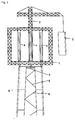
- Fig. 1 shows in front view the upper portion of a conventionally constructed stump stump 6. It has at least three levels, of which the two uppermost complete, the underlying is only one-third. The levels have in this example four prefabricated reinforced concrete elements 3 in the form of quarter shells. The thickness of these shells is indicated by a dashed line. Adjacent precast reinforced concrete elements are interconnected by truss prefabricated elements 8 . In Fig. 1 are only the two front reinforced concrete precast elements 3 and connecting them Truss pre-fabricated element 8 recognizable. The two rear reinforced concrete precast elements are concealed from the front. Also concealed are the truss prefabricated element that connects the two rear reinforced concrete precast elements, and two other truss prefabricated elements 8 , each connecting a front and a rear reinforced concrete precast element.
- the construction 1 is positioned with the attached crane 2 by the executed as hydraulic presses 4 supports of the lifting device connected to the construction 1 are offset to cross struts 5. Only one cross strut 5 is in Fig. 1 recognizable, the rest are hidden.
- the hydraulic presses 4 can be in the retracted state 4e or in the extended state 4a .
- Fig. 1 are all hydraulic presses in the retracted state 4e. Shown is a situation at the beginning of the process step a) i) described above, in which the crane 2 fixed to the structure 1 raises a first precast reinforced concrete element 3 required for a new level, in order to free it in the space spanned by the structure 1 to position the already finished stump 6 .
- Fig. 2 shows the situation after completion of the process step a) i): All reinforced concrete precast elements, which form the new level 7 , are positioned in the space spanned by the construction and placed on the stump of the tower. The crane 2 is relieved. The truss prefabricated elements to be positioned between the reinforced concrete precast elements can not yet be installed because the interstices between the prefabricated reinforced concrete elements are still occupied by the structure 1.
- Fig. 3 shows the situation after completion of the process step a) ii):
- the construction with the crane 2 has been raised by the extended four hydraulic presses 4a of their lifting device so far that it is now above the last built level 7 .
- All four hydraulic presses 4a placed on transverse struts 5 carry the construction 1 with the crane 2, whereby, as described above, the carrying capacity of three hydraulic presses is already sufficient to securely hold the construction in position with the crane.
- Fig. 4 shows the situation after completion of the process step a) iii):
- a hydraulic press 4e was moved upwards and on a near the top of the last built-up levels 7 newly inserted cross strut 5 ' deposed.
- the hydraulic press was moved horizontally in the direction of the tower axis according to the taper of the tower.
- a truss prefabricated element 8 was installed below the crossbar 5 ' .
- the three other hydraulic presses 4a are still in the extended state, two of them are in Fig. 4 visible, the third (on the back of the tower) is hidden.
- the successive retraction of these hydraulic presses 4a is indicated by vertical arrows, their horizontal displacement by horizontal arrows.
- the positioning of the other cross braces and truss pre-fabricated elements is not represented by illustrations.
- Fig. 5 shows a built-up closed concrete tower with a bottom open construction 11 , the lower frame sections, designed as cantilevers 15 , are attached to the outer walls of the highest level at this time level.
- the attached crane 13 is equipped with a lifting device with four supports, designed as hydraulic presses 14 .
- the two visible hydraulic presses 14 cover two hydraulic presses behind. It is the situation after the conclusion of the A previously completed tower stump 6, of which the uppermost one and a half levels are shown, has been set to a new level 7 by means of the method (steps b) i) to iv)) according to the invention.
- the levels are constructed of prefabricated reinforced concrete elements 10 , which are preferably designed as quarter, third or half shells or, at low tower diameter, as full circle elements, ie solid shells in the form of a hollow truncated cone.
- the structure 11 was lifted by a level height by extending the hydraulic presses 14 of the crane 13 connected to it.
- Their lower frame sections, which are designed as cantilevers 15 were extended in the direction of the tower and made a stable loadable connection of the structure 11 to the reinforced concrete precast elements of the uppermost level.
- the thus-mounted structure 11 is capable of the crane 13 , even if it is loaded to the maximum, z. B. with a reinforced concrete precast element to wear.
- the lifting device of the crane can now be relieved by retracting the hydraulic presses 14 of the lifting device and, preferably, folding them in the direction of the upper side of the construction in order to release the space spanned by the construction.
- another level of precast reinforced concrete elements or a steel tube level (of an optional tubular steel tower) or an assembly to be placed on the spire, e.g. B. the nacelle of a wind turbine be positioned.
- the middle connecting frame section in Fig. 5 behind the drawing plane and thus, like the other two connecting frame sections, runs outside the tower.
- Fig. 6 shows the positioning of the assembly using the example of the nacelle of a WTG.
- the nacelle has two parts in this example.
- Fig. 6a shows the rear part of the nacelle, which is to be mounted directly on the spire, raised.
- Fig. 6b shows the front part of the nacelle, which is to be connected to the rear part of the nacelle, raised.
- Fig. 6c shows, successively raised the rotor blades of the WEA and connected to the nacelle.
- Fig. 7 Figure 3 therefore shows a three-dimensional calculation model of a downwardly open structure 11 which is directly usable for constructing a closed concrete tower as well as all forms of a hybrid tower. It can be placed on the stump of such a concrete tower and raised with the growing tower, wherein it adapts to the outer diameter of the generally tapered tower.
- the tower is in Fig. 7 not shown.
- the construction has an attached crane, which in Fig. 7 also not shown.
- the construction 11 is embodied in three streams: Three horizontal upper frame sections 16 originate from a common starting point. They are arranged symmetrically, ie their directions are offset by 120 °. At their outer ends, these upper frame sections are connected to connecting frame sections 17 running vertically here, which in turn are connected at their lower ends to horizontal lower frame sections 18 .
- the entire construction is thus symmetrical and has in the center a perpendicular axis of symmetry (not shown).
- the symmetry axis is a threefold axis of rotation.
- the lower frame portions 18 are designed as hydraulic cantilevers which are extendable in the direction of the axis of symmetry. They have connections 12 to the tower, not shown.
- All frame sections are designed as a steel framework.
- the length of the horizontal upper frame sections and the vertically extending connecting frame sections is chosen so that the free space spanned by the construction is sufficiently large to accommodate both a new level and the assembly to be positioned on the tower top in that space.
- Parts of the assembly eg. As the rotor blades of a WEA, can extend beyond this space. The movement of the rotor blades may be hindered during construction of the WEA by the construction. After the final dismantling of the construction, the rotor blades gain their full mobility.
- trailing scaffolding levels can be installed for the workers inside the tower and / or outside the tower (not shown in the figures), which are also raised with the growing tower.
- the crane mounted on the construction does not have to be installed centrally, that is to say at the point of contact of the upper frame sections, but can also be eccentric, ie. H. be placed at any point of an upper frame portion.
- a second, placed at an arbitrary position of the lower frame sections crane This crane takes over tasks of the first, on top, crane, z.
Priority Applications (1)
| Application Number | Priority Date | Filing Date | Title |
|---|---|---|---|
| EP16156324.2A EP3208405B1 (fr) | 2016-02-18 | 2016-02-18 | Dispositif et procédé de montage de constructions en forme de tours à partir d'éléments préfabriqués |
Applications Claiming Priority (1)
| Application Number | Priority Date | Filing Date | Title |
|---|---|---|---|
| EP16156324.2A EP3208405B1 (fr) | 2016-02-18 | 2016-02-18 | Dispositif et procédé de montage de constructions en forme de tours à partir d'éléments préfabriqués |
Publications (2)
| Publication Number | Publication Date |
|---|---|
| EP3208405A1 true EP3208405A1 (fr) | 2017-08-23 |
| EP3208405B1 EP3208405B1 (fr) | 2020-05-20 |
Family
ID=55524087
Family Applications (1)
| Application Number | Title | Priority Date | Filing Date |
|---|---|---|---|
| EP16156324.2A Active EP3208405B1 (fr) | 2016-02-18 | 2016-02-18 | Dispositif et procédé de montage de constructions en forme de tours à partir d'éléments préfabriqués |
Country Status (1)
| Country | Link |
|---|---|
| EP (1) | EP3208405B1 (fr) |
Cited By (4)
| Publication number | Priority date | Publication date | Assignee | Title |
|---|---|---|---|---|
| CN113023600A (zh) * | 2021-02-01 | 2021-06-25 | 广州中穗建设有限公司 | 一种装配式建筑混凝土预制柱定位导向装置 |
| CN115492398A (zh) * | 2022-09-14 | 2022-12-20 | 中国化学工程第六建设有限公司 | 冷却造粒塔现场组装施工方法 |
| WO2023126039A1 (fr) * | 2021-12-30 | 2023-07-06 | Vestas Wind Systems A/S | Grue à tour pour ériger partiellement une éolienne et son procédé d'utilisation |
| WO2023126038A1 (fr) * | 2021-12-30 | 2023-07-06 | Vestas Wind Systems A/S | Grue à tour pour ériger partiellement une éolienne et son procédé d'utilisation |
Families Citing this family (1)
| Publication number | Priority date | Publication date | Assignee | Title |
|---|---|---|---|---|
| CN112429666B (zh) * | 2020-10-16 | 2022-07-08 | 中国能源建设集团湖南火电建设有限公司 | 一种兆瓦级塔式光热发电集热器安装方法及安装系统装置 |
Citations (6)
| Publication number | Priority date | Publication date | Assignee | Title |
|---|---|---|---|---|
| CA2491949A1 (fr) * | 2005-01-11 | 2006-07-11 | Valmont Industries, Inc. | Methodes et dispositif d'erection d'une tour eolienne |
| EP1857670A1 (fr) * | 2006-05-20 | 2007-11-21 | W2E Wind to Energy GmbH | Méthode et dispositif pour l'érection d'une tour d'une éolienne, la tour comprenant des segments |
| WO2009056898A1 (fr) | 2007-11-02 | 2009-05-07 | Alejandro Cortina-Cordero | Tour en béton postcontraint pour génératrices éoliennes |
| WO2009137445A1 (fr) * | 2008-05-07 | 2009-11-12 | Babcock & Wilcox Power Generation Group Inc. | Procédé d’édification pour récepteur solaire et tour de support |
| EP2746571A2 (fr) * | 2012-12-21 | 2014-06-25 | Acciona Windpower S.a. | Système de transmission pour éolienne |
| EP2851328A1 (fr) | 2012-05-18 | 2015-03-25 | Structural Research S.L. | Grue télescopique auto-escamotable et procédé de montage de tours préfabriquées en béton |
-
2016
- 2016-02-18 EP EP16156324.2A patent/EP3208405B1/fr active Active
Patent Citations (6)
| Publication number | Priority date | Publication date | Assignee | Title |
|---|---|---|---|---|
| CA2491949A1 (fr) * | 2005-01-11 | 2006-07-11 | Valmont Industries, Inc. | Methodes et dispositif d'erection d'une tour eolienne |
| EP1857670A1 (fr) * | 2006-05-20 | 2007-11-21 | W2E Wind to Energy GmbH | Méthode et dispositif pour l'érection d'une tour d'une éolienne, la tour comprenant des segments |
| WO2009056898A1 (fr) | 2007-11-02 | 2009-05-07 | Alejandro Cortina-Cordero | Tour en béton postcontraint pour génératrices éoliennes |
| WO2009137445A1 (fr) * | 2008-05-07 | 2009-11-12 | Babcock & Wilcox Power Generation Group Inc. | Procédé d’édification pour récepteur solaire et tour de support |
| EP2851328A1 (fr) | 2012-05-18 | 2015-03-25 | Structural Research S.L. | Grue télescopique auto-escamotable et procédé de montage de tours préfabriquées en béton |
| EP2746571A2 (fr) * | 2012-12-21 | 2014-06-25 | Acciona Windpower S.a. | Système de transmission pour éolienne |
Cited By (5)
| Publication number | Priority date | Publication date | Assignee | Title |
|---|---|---|---|---|
| CN113023600A (zh) * | 2021-02-01 | 2021-06-25 | 广州中穗建设有限公司 | 一种装配式建筑混凝土预制柱定位导向装置 |
| CN113023600B (zh) * | 2021-02-01 | 2022-07-29 | 广州中穗建设有限公司 | 一种装配式建筑混凝土预制柱定位导向装置 |
| WO2023126039A1 (fr) * | 2021-12-30 | 2023-07-06 | Vestas Wind Systems A/S | Grue à tour pour ériger partiellement une éolienne et son procédé d'utilisation |
| WO2023126038A1 (fr) * | 2021-12-30 | 2023-07-06 | Vestas Wind Systems A/S | Grue à tour pour ériger partiellement une éolienne et son procédé d'utilisation |
| CN115492398A (zh) * | 2022-09-14 | 2022-12-20 | 中国化学工程第六建设有限公司 | 冷却造粒塔现场组装施工方法 |
Also Published As
| Publication number | Publication date |
|---|---|
| EP3208405B1 (fr) | 2020-05-20 |
Similar Documents
| Publication | Publication Date | Title |
|---|---|---|
| EP2715115B1 (fr) | Dispositif destiné à ériger une éolienne | |
| DE60309668T3 (de) | Windkraftanlage | |
| EP3208405B1 (fr) | Dispositif et procédé de montage de constructions en forme de tours à partir d'éléments préfabriqués | |
| DE102008055607A1 (de) | Verfahren zum Errichten eines segmentierten Turms aus Spannbeton für Windkraftanlagen und Turm für Windkraftanlagen | |
| WO2004101898A2 (fr) | Fondations pour installation d'energie eolienne | |
| AT521432B1 (de) | Fundament für ein Windkraftwerk | |
| DE202011100477U1 (de) | Turmdrehkran | |
| DE102009014926A1 (de) | Turm | |
| EP3208404B1 (fr) | Procédé et dispositif de montage d'un mât tubulaire | |
| EP3477099A1 (fr) | Tour pourvue d'éléments adaptateurs en acier coniques | |
| WO2005097661A1 (fr) | Grue a contrepoids stationnaire | |
| AT413042B (de) | Innenschalungsabschnitt zur errichtung eines bauwerksabschnitts | |
| DE7301816U (de) | Vorrichtung zur errichtung von vorzugsweise umfanggeschlossenen betonbauten | |
| EP2712985B1 (fr) | Procédé de création d'une tour, notamment une tour d'éolienne | |
| DE102005014025A1 (de) | Als Stahlfachwerkkonstruktion ausgebildeter Turm, vorzugsweise für Windkraftanlagen | |
| EP0098962B1 (fr) | Echafaudage de montage pour coffrages pour éfifices circulaires en béton ou similaires | |
| EP3382195B1 (fr) | Utilisation des moyens de transport lors de la construction des éoliennes et aide au montage | |
| CH632083A5 (de) | Kuehlturm. | |
| DE102016102213A1 (de) | Verfahren zum Errichten eines Windkraftturms einer Windkraftanlage mittels eines Krans, Windkraftturm sowie Stahlsegment für einen Windkraftturm einer Windkraftanlage | |
| DE2460742C3 (de) | Schalung zur Herstellung kegelförmiger Bauwerksteile | |
| DE2645910A1 (de) | Schalung sowie verfahren zur errichtung trichter- oder kegelfoermiger betonbauten | |
| DE102010012408A1 (de) | Trägeranordnung für eine Windenergieanlage, Windenergieanlage mit einer Trägeranordnung und Verfahren zum Errichten einer Windenergieanlage | |
| WO1984000189A1 (fr) | Procede pour le betonnage de parois et coffrage pour sa mise en oeuvre | |
| EP3704333B1 (fr) | Procédé d'édification d'une tour ayant une section de tour en plusieurs parties | |
| DE2824744A1 (de) | Kuehlturm und verfahren zu seiner herstellung |
Legal Events
| Date | Code | Title | Description |
|---|---|---|---|
| PUAI | Public reference made under article 153(3) epc to a published international application that has entered the european phase |
Free format text: ORIGINAL CODE: 0009012 |
|
| STAA | Information on the status of an ep patent application or granted ep patent |
Free format text: STATUS: THE APPLICATION HAS BEEN PUBLISHED |
|
| AK | Designated contracting states |
Kind code of ref document: A1 Designated state(s): AL AT BE BG CH CY CZ DE DK EE ES FI FR GB GR HR HU IE IS IT LI LT LU LV MC MK MT NL NO PL PT RO RS SE SI SK SM TR |
|
| AX | Request for extension of the european patent |
Extension state: BA ME |
|
| STAA | Information on the status of an ep patent application or granted ep patent |
Free format text: STATUS: REQUEST FOR EXAMINATION WAS MADE |
|
| 17P | Request for examination filed |
Effective date: 20180223 |
|
| RBV | Designated contracting states (corrected) |
Designated state(s): AL AT BE BG CH CY CZ DE DK EE ES FI FR GB GR HR HU IE IS IT LI LT LU LV MC MK MT NL NO PL PT RO RS SE SI SK SM TR |
|
| STAA | Information on the status of an ep patent application or granted ep patent |
Free format text: STATUS: EXAMINATION IS IN PROGRESS |
|
| 17Q | First examination report despatched |
Effective date: 20181004 |
|
| RIN1 | Information on inventor provided before grant (corrected) |
Inventor name: BLATT, MARKUS |
|
| GRAP | Despatch of communication of intention to grant a patent |
Free format text: ORIGINAL CODE: EPIDOSNIGR1 |
|
| STAA | Information on the status of an ep patent application or granted ep patent |
Free format text: STATUS: GRANT OF PATENT IS INTENDED |
|
| INTG | Intention to grant announced |
Effective date: 20191205 |
|
| GRAS | Grant fee paid |
Free format text: ORIGINAL CODE: EPIDOSNIGR3 |
|
| GRAA | (expected) grant |
Free format text: ORIGINAL CODE: 0009210 |
|
| STAA | Information on the status of an ep patent application or granted ep patent |
Free format text: STATUS: THE PATENT HAS BEEN GRANTED |
|
| AK | Designated contracting states |
Kind code of ref document: B1 Designated state(s): AL AT BE BG CH CY CZ DE DK EE ES FI FR GB GR HR HU IE IS IT LI LT LU LV MC MK MT NL NO PL PT RO RS SE SI SK SM TR |
|
| REG | Reference to a national code |
Ref country code: GB Ref legal event code: FG4D Free format text: NOT ENGLISH |
|
| REG | Reference to a national code |
Ref country code: CH Ref legal event code: EP |
|
| REG | Reference to a national code |
Ref country code: DE Ref legal event code: R096 Ref document number: 502016009976 Country of ref document: DE |
|
| REG | Reference to a national code |
Ref country code: AT Ref legal event code: REF Ref document number: 1272688 Country of ref document: AT Kind code of ref document: T Effective date: 20200615 |
|
| REG | Reference to a national code |
Ref country code: LT Ref legal event code: MG4D |
|
| REG | Reference to a national code |
Ref country code: NL Ref legal event code: MP Effective date: 20200520 |
|
| PG25 | Lapsed in a contracting state [announced via postgrant information from national office to epo] |
Ref country code: SE Free format text: LAPSE BECAUSE OF FAILURE TO SUBMIT A TRANSLATION OF THE DESCRIPTION OR TO PAY THE FEE WITHIN THE PRESCRIBED TIME-LIMIT Effective date: 20200520 Ref country code: NO Free format text: LAPSE BECAUSE OF FAILURE TO SUBMIT A TRANSLATION OF THE DESCRIPTION OR TO PAY THE FEE WITHIN THE PRESCRIBED TIME-LIMIT Effective date: 20200820 Ref country code: FI Free format text: LAPSE BECAUSE OF FAILURE TO SUBMIT A TRANSLATION OF THE DESCRIPTION OR TO PAY THE FEE WITHIN THE PRESCRIBED TIME-LIMIT Effective date: 20200520 Ref country code: GR Free format text: LAPSE BECAUSE OF FAILURE TO SUBMIT A TRANSLATION OF THE DESCRIPTION OR TO PAY THE FEE WITHIN THE PRESCRIBED TIME-LIMIT Effective date: 20200821 Ref country code: IS Free format text: LAPSE BECAUSE OF FAILURE TO SUBMIT A TRANSLATION OF THE DESCRIPTION OR TO PAY THE FEE WITHIN THE PRESCRIBED TIME-LIMIT Effective date: 20200920 Ref country code: PT Free format text: LAPSE BECAUSE OF FAILURE TO SUBMIT A TRANSLATION OF THE DESCRIPTION OR TO PAY THE FEE WITHIN THE PRESCRIBED TIME-LIMIT Effective date: 20200921 Ref country code: LT Free format text: LAPSE BECAUSE OF FAILURE TO SUBMIT A TRANSLATION OF THE DESCRIPTION OR TO PAY THE FEE WITHIN THE PRESCRIBED TIME-LIMIT Effective date: 20200520 |
|
| PG25 | Lapsed in a contracting state [announced via postgrant information from national office to epo] |
Ref country code: RS Free format text: LAPSE BECAUSE OF FAILURE TO SUBMIT A TRANSLATION OF THE DESCRIPTION OR TO PAY THE FEE WITHIN THE PRESCRIBED TIME-LIMIT Effective date: 20200520 Ref country code: BG Free format text: LAPSE BECAUSE OF FAILURE TO SUBMIT A TRANSLATION OF THE DESCRIPTION OR TO PAY THE FEE WITHIN THE PRESCRIBED TIME-LIMIT Effective date: 20200820 Ref country code: HR Free format text: LAPSE BECAUSE OF FAILURE TO SUBMIT A TRANSLATION OF THE DESCRIPTION OR TO PAY THE FEE WITHIN THE PRESCRIBED TIME-LIMIT Effective date: 20200520 Ref country code: LV Free format text: LAPSE BECAUSE OF FAILURE TO SUBMIT A TRANSLATION OF THE DESCRIPTION OR TO PAY THE FEE WITHIN THE PRESCRIBED TIME-LIMIT Effective date: 20200520 |
|
| PG25 | Lapsed in a contracting state [announced via postgrant information from national office to epo] |
Ref country code: NL Free format text: LAPSE BECAUSE OF FAILURE TO SUBMIT A TRANSLATION OF THE DESCRIPTION OR TO PAY THE FEE WITHIN THE PRESCRIBED TIME-LIMIT Effective date: 20200520 Ref country code: AL Free format text: LAPSE BECAUSE OF FAILURE TO SUBMIT A TRANSLATION OF THE DESCRIPTION OR TO PAY THE FEE WITHIN THE PRESCRIBED TIME-LIMIT Effective date: 20200520 |
|
| PG25 | Lapsed in a contracting state [announced via postgrant information from national office to epo] |
Ref country code: EE Free format text: LAPSE BECAUSE OF FAILURE TO SUBMIT A TRANSLATION OF THE DESCRIPTION OR TO PAY THE FEE WITHIN THE PRESCRIBED TIME-LIMIT Effective date: 20200520 Ref country code: SM Free format text: LAPSE BECAUSE OF FAILURE TO SUBMIT A TRANSLATION OF THE DESCRIPTION OR TO PAY THE FEE WITHIN THE PRESCRIBED TIME-LIMIT Effective date: 20200520 Ref country code: DK Free format text: LAPSE BECAUSE OF FAILURE TO SUBMIT A TRANSLATION OF THE DESCRIPTION OR TO PAY THE FEE WITHIN THE PRESCRIBED TIME-LIMIT Effective date: 20200520 Ref country code: ES Free format text: LAPSE BECAUSE OF FAILURE TO SUBMIT A TRANSLATION OF THE DESCRIPTION OR TO PAY THE FEE WITHIN THE PRESCRIBED TIME-LIMIT Effective date: 20200520 Ref country code: RO Free format text: LAPSE BECAUSE OF FAILURE TO SUBMIT A TRANSLATION OF THE DESCRIPTION OR TO PAY THE FEE WITHIN THE PRESCRIBED TIME-LIMIT Effective date: 20200520 Ref country code: IT Free format text: LAPSE BECAUSE OF FAILURE TO SUBMIT A TRANSLATION OF THE DESCRIPTION OR TO PAY THE FEE WITHIN THE PRESCRIBED TIME-LIMIT Effective date: 20200520 Ref country code: CZ Free format text: LAPSE BECAUSE OF FAILURE TO SUBMIT A TRANSLATION OF THE DESCRIPTION OR TO PAY THE FEE WITHIN THE PRESCRIBED TIME-LIMIT Effective date: 20200520 |
|
| REG | Reference to a national code |
Ref country code: DE Ref legal event code: R097 Ref document number: 502016009976 Country of ref document: DE |
|
| PG25 | Lapsed in a contracting state [announced via postgrant information from national office to epo] |
Ref country code: PL Free format text: LAPSE BECAUSE OF FAILURE TO SUBMIT A TRANSLATION OF THE DESCRIPTION OR TO PAY THE FEE WITHIN THE PRESCRIBED TIME-LIMIT Effective date: 20200520 Ref country code: SK Free format text: LAPSE BECAUSE OF FAILURE TO SUBMIT A TRANSLATION OF THE DESCRIPTION OR TO PAY THE FEE WITHIN THE PRESCRIBED TIME-LIMIT Effective date: 20200520 |
|
| PLBE | No opposition filed within time limit |
Free format text: ORIGINAL CODE: 0009261 |
|
| STAA | Information on the status of an ep patent application or granted ep patent |
Free format text: STATUS: NO OPPOSITION FILED WITHIN TIME LIMIT |
|
| 26N | No opposition filed |
Effective date: 20210223 |
|
| PG25 | Lapsed in a contracting state [announced via postgrant information from national office to epo] |
Ref country code: SI Free format text: LAPSE BECAUSE OF FAILURE TO SUBMIT A TRANSLATION OF THE DESCRIPTION OR TO PAY THE FEE WITHIN THE PRESCRIBED TIME-LIMIT Effective date: 20200520 |
|
| PG25 | Lapsed in a contracting state [announced via postgrant information from national office to epo] |
Ref country code: MC Free format text: LAPSE BECAUSE OF FAILURE TO SUBMIT A TRANSLATION OF THE DESCRIPTION OR TO PAY THE FEE WITHIN THE PRESCRIBED TIME-LIMIT Effective date: 20200520 |
|
| GBPC | Gb: european patent ceased through non-payment of renewal fee |
Effective date: 20210218 |
|
| REG | Reference to a national code |
Ref country code: BE Ref legal event code: MM Effective date: 20210228 |
|
| PG25 | Lapsed in a contracting state [announced via postgrant information from national office to epo] |
Ref country code: CH Free format text: LAPSE BECAUSE OF NON-PAYMENT OF DUE FEES Effective date: 20210228 Ref country code: LU Free format text: LAPSE BECAUSE OF NON-PAYMENT OF DUE FEES Effective date: 20210218 Ref country code: LI Free format text: LAPSE BECAUSE OF NON-PAYMENT OF DUE FEES Effective date: 20210228 |
|
| PG25 | Lapsed in a contracting state [announced via postgrant information from national office to epo] |
Ref country code: IE Free format text: LAPSE BECAUSE OF NON-PAYMENT OF DUE FEES Effective date: 20210218 Ref country code: FR Free format text: LAPSE BECAUSE OF NON-PAYMENT OF DUE FEES Effective date: 20210228 Ref country code: GB Free format text: LAPSE BECAUSE OF NON-PAYMENT OF DUE FEES Effective date: 20210218 |
|
| REG | Reference to a national code |
Ref country code: AT Ref legal event code: MM01 Ref document number: 1272688 Country of ref document: AT Kind code of ref document: T Effective date: 20210218 |
|
| PG25 | Lapsed in a contracting state [announced via postgrant information from national office to epo] |
Ref country code: AT Free format text: LAPSE BECAUSE OF NON-PAYMENT OF DUE FEES Effective date: 20210218 |
|
| PG25 | Lapsed in a contracting state [announced via postgrant information from national office to epo] |
Ref country code: BE Free format text: LAPSE BECAUSE OF NON-PAYMENT OF DUE FEES Effective date: 20210228 |
|
| PG25 | Lapsed in a contracting state [announced via postgrant information from national office to epo] |
Ref country code: HU Free format text: LAPSE BECAUSE OF FAILURE TO SUBMIT A TRANSLATION OF THE DESCRIPTION OR TO PAY THE FEE WITHIN THE PRESCRIBED TIME-LIMIT; INVALID AB INITIO Effective date: 20160218 |
|
| PG25 | Lapsed in a contracting state [announced via postgrant information from national office to epo] |
Ref country code: CY Free format text: LAPSE BECAUSE OF FAILURE TO SUBMIT A TRANSLATION OF THE DESCRIPTION OR TO PAY THE FEE WITHIN THE PRESCRIBED TIME-LIMIT Effective date: 20200520 |
|
| PG25 | Lapsed in a contracting state [announced via postgrant information from national office to epo] |
Ref country code: MK Free format text: LAPSE BECAUSE OF FAILURE TO SUBMIT A TRANSLATION OF THE DESCRIPTION OR TO PAY THE FEE WITHIN THE PRESCRIBED TIME-LIMIT Effective date: 20200520 |
|
| PGFP | Annual fee paid to national office [announced via postgrant information from national office to epo] |
Ref country code: DE Payment date: 20240229 Year of fee payment: 9 |