EP3207953B1 - Piston de seringue revêtu d'eptfe - Google Patents
Piston de seringue revêtu d'eptfe Download PDFInfo
- Publication number
- EP3207953B1 EP3207953B1 EP17161692.3A EP17161692A EP3207953B1 EP 3207953 B1 EP3207953 B1 EP 3207953B1 EP 17161692 A EP17161692 A EP 17161692A EP 3207953 B1 EP3207953 B1 EP 3207953B1
- Authority
- EP
- European Patent Office
- Prior art keywords
- barrier
- stopper
- syringe
- eptfe
- layer
- Prior art date
- Legal status (The legal status is an assumption and is not a legal conclusion. Google has not performed a legal analysis and makes no representation as to the accuracy of the status listed.)
- Active
Links
- 229920001343 polytetrafluoroethylene Polymers 0.000 title claims description 13
- 230000004888 barrier function Effects 0.000 claims description 120
- 229920000295 expanded polytetrafluoroethylene Polymers 0.000 claims description 90
- 229920001971 elastomer Polymers 0.000 claims description 65
- 229920002313 fluoropolymer Polymers 0.000 claims description 28
- 239000004811 fluoropolymer Substances 0.000 claims description 28
- 229920000642 polymer Polymers 0.000 claims description 17
- 239000004812 Fluorinated ethylene propylene Substances 0.000 claims description 14
- 229920009441 perflouroethylene propylene Polymers 0.000 claims description 14
- 239000004810 polytetrafluoroethylene Substances 0.000 claims description 12
- -1 polytetrafluoroethylene Polymers 0.000 claims description 11
- 229920001296 polysiloxane Polymers 0.000 claims description 7
- 125000000484 butyl group Chemical group [H]C([*])([H])C([H])([H])C([H])([H])C([H])([H])[H] 0.000 claims description 5
- 239000000203 mixture Substances 0.000 claims description 3
- 150000002825 nitriles Chemical class 0.000 claims description 3
- 239000005060 rubber Substances 0.000 claims description 3
- 229920003048 styrene butadiene rubber Polymers 0.000 claims description 3
- 239000002033 PVDF binder Substances 0.000 claims description 2
- 229920001774 Perfluoroether Polymers 0.000 claims description 2
- 239000004698 Polyethylene Substances 0.000 claims description 2
- 239000004743 Polypropylene Substances 0.000 claims description 2
- 239000002174 Styrene-butadiene Substances 0.000 claims description 2
- 229920005557 bromobutyl Polymers 0.000 claims description 2
- MTAZNLWOLGHBHU-UHFFFAOYSA-N butadiene-styrene rubber Chemical compound C=CC=C.C=CC1=CC=CC=C1 MTAZNLWOLGHBHU-UHFFFAOYSA-N 0.000 claims description 2
- 229920005556 chlorobutyl Polymers 0.000 claims description 2
- HQQADJVZYDDRJT-UHFFFAOYSA-N ethene;prop-1-ene Chemical group C=C.CC=C HQQADJVZYDDRJT-UHFFFAOYSA-N 0.000 claims description 2
- 229920001973 fluoroelastomer Polymers 0.000 claims description 2
- 229920001084 poly(chloroprene) Polymers 0.000 claims description 2
- 229920000573 polyethylene Polymers 0.000 claims description 2
- 229920001155 polypropylene Polymers 0.000 claims description 2
- 229920002620 polyvinyl fluoride Polymers 0.000 claims description 2
- 229920002981 polyvinylidene fluoride Polymers 0.000 claims description 2
- 239000011115 styrene butadiene Substances 0.000 claims description 2
- 239000000314 lubricant Substances 0.000 claims 1
- 239000010410 layer Substances 0.000 description 97
- 239000010408 film Substances 0.000 description 74
- 239000000806 elastomer Substances 0.000 description 62
- 239000002131 composite material Substances 0.000 description 39
- 238000000034 method Methods 0.000 description 36
- 239000000463 material Substances 0.000 description 30
- 238000012360 testing method Methods 0.000 description 27
- 230000008569 process Effects 0.000 description 25
- 239000000523 sample Substances 0.000 description 18
- 238000003856 thermoforming Methods 0.000 description 17
- YXFVVABEGXRONW-UHFFFAOYSA-N Toluene Chemical compound CC1=CC=CC=C1 YXFVVABEGXRONW-UHFFFAOYSA-N 0.000 description 15
- 239000011148 porous material Substances 0.000 description 12
- 238000000748 compression moulding Methods 0.000 description 11
- 229920002545 silicone oil Polymers 0.000 description 11
- 239000003814 drug Substances 0.000 description 9
- 239000012632 extractable Substances 0.000 description 8
- 239000011521 glass Substances 0.000 description 8
- 239000012633 leachable Substances 0.000 description 8
- 230000035515 penetration Effects 0.000 description 8
- 238000010276 construction Methods 0.000 description 7
- 238000000465 moulding Methods 0.000 description 6
- VLKZOEOYAKHREP-UHFFFAOYSA-N n-Hexane Chemical compound CCCCCC VLKZOEOYAKHREP-UHFFFAOYSA-N 0.000 description 6
- 229920001169 thermoplastic Polymers 0.000 description 6
- 239000004416 thermosoftening plastic Substances 0.000 description 6
- 238000001746 injection moulding Methods 0.000 description 5
- 239000004033 plastic Substances 0.000 description 5
- 229920003023 plastic Polymers 0.000 description 5
- 239000011347 resin Substances 0.000 description 5
- 229920005989 resin Polymers 0.000 description 5
- 238000007789 sealing Methods 0.000 description 5
- 230000003068 static effect Effects 0.000 description 5
- 229960000074 biopharmaceutical Drugs 0.000 description 4
- 238000010438 heat treatment Methods 0.000 description 4
- 239000007924 injection Substances 0.000 description 4
- 238000003780 insertion Methods 0.000 description 4
- 230000037431 insertion Effects 0.000 description 4
- 239000003921 oil Substances 0.000 description 4
- 229940071643 prefilled syringe Drugs 0.000 description 4
- 230000004584 weight gain Effects 0.000 description 4
- 235000019786 weight gain Nutrition 0.000 description 4
- 238000000576 coating method Methods 0.000 description 3
- 230000000052 comparative effect Effects 0.000 description 3
- 239000008367 deionised water Substances 0.000 description 3
- 238000009434 installation Methods 0.000 description 3
- 230000036961 partial effect Effects 0.000 description 3
- 230000002829 reductive effect Effects 0.000 description 3
- 239000002356 single layer Substances 0.000 description 3
- 239000000243 solution Substances 0.000 description 3
- 230000003746 surface roughness Effects 0.000 description 3
- XLYOFNOQVPJJNP-UHFFFAOYSA-N water Chemical compound O XLYOFNOQVPJJNP-UHFFFAOYSA-N 0.000 description 3
- 239000000853 adhesive Substances 0.000 description 2
- 230000001070 adhesive effect Effects 0.000 description 2
- 230000002411 adverse Effects 0.000 description 2
- 229920005549 butyl rubber Polymers 0.000 description 2
- 239000011248 coating agent Substances 0.000 description 2
- 239000000356 contaminant Substances 0.000 description 2
- 239000011162 core material Substances 0.000 description 2
- 229910021641 deionized water Inorganic materials 0.000 description 2
- 238000011049 filling Methods 0.000 description 2
- NOESYZHRGYRDHS-UHFFFAOYSA-N insulin Chemical compound N1C(=O)C(NC(=O)C(CCC(N)=O)NC(=O)C(CCC(O)=O)NC(=O)C(C(C)C)NC(=O)C(NC(=O)CN)C(C)CC)CSSCC(C(NC(CO)C(=O)NC(CC(C)C)C(=O)NC(CC=2C=CC(O)=CC=2)C(=O)NC(CCC(N)=O)C(=O)NC(CC(C)C)C(=O)NC(CCC(O)=O)C(=O)NC(CC(N)=O)C(=O)NC(CC=2C=CC(O)=CC=2)C(=O)NC(CSSCC(NC(=O)C(C(C)C)NC(=O)C(CC(C)C)NC(=O)C(CC=2C=CC(O)=CC=2)NC(=O)C(CC(C)C)NC(=O)C(C)NC(=O)C(CCC(O)=O)NC(=O)C(C(C)C)NC(=O)C(CC(C)C)NC(=O)C(CC=2NC=NC=2)NC(=O)C(CO)NC(=O)CNC2=O)C(=O)NCC(=O)NC(CCC(O)=O)C(=O)NC(CCCNC(N)=N)C(=O)NCC(=O)NC(CC=3C=CC=CC=3)C(=O)NC(CC=3C=CC=CC=3)C(=O)NC(CC=3C=CC(O)=CC=3)C(=O)NC(C(C)O)C(=O)N3C(CCC3)C(=O)NC(CCCCN)C(=O)NC(C)C(O)=O)C(=O)NC(CC(N)=O)C(O)=O)=O)NC(=O)C(C(C)CC)NC(=O)C(CO)NC(=O)C(C(C)O)NC(=O)C1CSSCC2NC(=O)C(CC(C)C)NC(=O)C(NC(=O)C(CCC(N)=O)NC(=O)C(CC(N)=O)NC(=O)C(NC(=O)C(N)CC=1C=CC=CC=1)C(C)C)CC1=CN=CN1 NOESYZHRGYRDHS-UHFFFAOYSA-N 0.000 description 2
- 238000010030 laminating Methods 0.000 description 2
- 238000007788 roughening Methods 0.000 description 2
- 229910001220 stainless steel Inorganic materials 0.000 description 2
- 239000010935 stainless steel Substances 0.000 description 2
- 238000003860 storage Methods 0.000 description 2
- 230000001225 therapeutic effect Effects 0.000 description 2
- DMWVYCCGCQPJEA-UHFFFAOYSA-N 2,5-bis(tert-butylperoxy)-2,5-dimethylhexane Chemical compound CC(C)(C)OOC(C)(C)CCC(C)(C)OOC(C)(C)C DMWVYCCGCQPJEA-UHFFFAOYSA-N 0.000 description 1
- 241000894006 Bacteria Species 0.000 description 1
- BJRMDQLATQGMCQ-UHFFFAOYSA-N C=C.C=CC=C.C=CC1=CC=CC=C1.C=CC1=CC=CC=C1 Chemical compound C=C.C=CC=C.C=CC1=CC=CC=C1.C=CC1=CC=CC=C1 BJRMDQLATQGMCQ-UHFFFAOYSA-N 0.000 description 1
- 102000004127 Cytokines Human genes 0.000 description 1
- 108090000695 Cytokines Proteins 0.000 description 1
- 229920002449 FKM Polymers 0.000 description 1
- 102000004877 Insulin Human genes 0.000 description 1
- 108090001061 Insulin Proteins 0.000 description 1
- 229910000831 Steel Inorganic materials 0.000 description 1
- 239000003522 acrylic cement Substances 0.000 description 1
- 230000002730 additional effect Effects 0.000 description 1
- 230000002776 aggregation Effects 0.000 description 1
- 238000004220 aggregation Methods 0.000 description 1
- 229910052782 aluminium Inorganic materials 0.000 description 1
- XAGFODPZIPBFFR-UHFFFAOYSA-N aluminium Chemical compound [Al] XAGFODPZIPBFFR-UHFFFAOYSA-N 0.000 description 1
- 239000011324 bead Substances 0.000 description 1
- 230000009286 beneficial effect Effects 0.000 description 1
- 230000015572 biosynthetic process Effects 0.000 description 1
- 239000010836 blood and blood product Substances 0.000 description 1
- 229940125691 blood product Drugs 0.000 description 1
- 238000003486 chemical etching Methods 0.000 description 1
- 238000004140 cleaning Methods 0.000 description 1
- 150000001875 compounds Chemical class 0.000 description 1
- 238000011109 contamination Methods 0.000 description 1
- 238000001816 cooling Methods 0.000 description 1
- 229920001577 copolymer Polymers 0.000 description 1
- 238000000151 deposition Methods 0.000 description 1
- 239000003599 detergent Substances 0.000 description 1
- 238000006073 displacement reaction Methods 0.000 description 1
- 230000000694 effects Effects 0.000 description 1
- 239000013536 elastomeric material Substances 0.000 description 1
- 238000005516 engineering process Methods 0.000 description 1
- 238000005530 etching Methods 0.000 description 1
- 238000001704 evaporation Methods 0.000 description 1
- 230000008020 evaporation Effects 0.000 description 1
- 238000000605 extraction Methods 0.000 description 1
- 239000012530 fluid Substances 0.000 description 1
- 239000007789 gas Substances 0.000 description 1
- 210000000569 greater omentum Anatomy 0.000 description 1
- 229920005555 halobutyl Polymers 0.000 description 1
- 125000004968 halobutyl group Chemical group 0.000 description 1
- 239000005556 hormone Substances 0.000 description 1
- 229940088597 hormone Drugs 0.000 description 1
- 239000012535 impurity Substances 0.000 description 1
- 230000036512 infertility Effects 0.000 description 1
- 238000002347 injection Methods 0.000 description 1
- 208000014674 injury Diseases 0.000 description 1
- 229910010272 inorganic material Inorganic materials 0.000 description 1
- 239000011147 inorganic material Substances 0.000 description 1
- 229940125396 insulin Drugs 0.000 description 1
- 238000002386 leaching Methods 0.000 description 1
- 230000000670 limiting effect Effects 0.000 description 1
- 239000007788 liquid Substances 0.000 description 1
- 230000007774 longterm Effects 0.000 description 1
- 239000010687 lubricating oil Substances 0.000 description 1
- 239000011159 matrix material Substances 0.000 description 1
- 239000000155 melt Substances 0.000 description 1
- 229910052751 metal Inorganic materials 0.000 description 1
- 239000002184 metal Substances 0.000 description 1
- 239000000178 monomer Substances 0.000 description 1
- 238000010068 moulding (rubber) Methods 0.000 description 1
- 230000003287 optical effect Effects 0.000 description 1
- 239000011368 organic material Substances 0.000 description 1
- 238000009832 plasma treatment Methods 0.000 description 1
- 239000004014 plasticizer Substances 0.000 description 1
- 229920002635 polyurethane Polymers 0.000 description 1
- 239000004814 polyurethane Substances 0.000 description 1
- 230000037452 priming Effects 0.000 description 1
- 230000001681 protective effect Effects 0.000 description 1
- 102000004169 proteins and genes Human genes 0.000 description 1
- 108090000623 proteins and genes Proteins 0.000 description 1
- 230000009467 reduction Effects 0.000 description 1
- 230000002787 reinforcement Effects 0.000 description 1
- 238000001878 scanning electron micrograph Methods 0.000 description 1
- 239000002904 solvent Substances 0.000 description 1
- 239000010959 steel Substances 0.000 description 1
- 229920001935 styrene-ethylene-butadiene-styrene Polymers 0.000 description 1
- 239000010409 thin film Substances 0.000 description 1
- 230000008733 trauma Effects 0.000 description 1
- 229960005486 vaccine Drugs 0.000 description 1
- 238000007666 vacuum forming Methods 0.000 description 1
- 230000000007 visual effect Effects 0.000 description 1
Images


Classifications
-
- B—PERFORMING OPERATIONS; TRANSPORTING
- B32—LAYERED PRODUCTS
- B32B—LAYERED PRODUCTS, i.e. PRODUCTS BUILT-UP OF STRATA OF FLAT OR NON-FLAT, e.g. CELLULAR OR HONEYCOMB, FORM
- B32B5/00—Layered products characterised by the non- homogeneity or physical structure, i.e. comprising a fibrous, filamentary, particulate or foam layer; Layered products characterised by having a layer differing constitutionally or physically in different parts
- B32B5/18—Layered products characterised by the non- homogeneity or physical structure, i.e. comprising a fibrous, filamentary, particulate or foam layer; Layered products characterised by having a layer differing constitutionally or physically in different parts characterised by features of a layer of foamed material
-
- A—HUMAN NECESSITIES
- A61—MEDICAL OR VETERINARY SCIENCE; HYGIENE
- A61M—DEVICES FOR INTRODUCING MEDIA INTO, OR ONTO, THE BODY; DEVICES FOR TRANSDUCING BODY MEDIA OR FOR TAKING MEDIA FROM THE BODY; DEVICES FOR PRODUCING OR ENDING SLEEP OR STUPOR
- A61M5/00—Devices for bringing media into the body in a subcutaneous, intra-vascular or intramuscular way; Accessories therefor, e.g. filling or cleaning devices, arm-rests
- A61M5/178—Syringes
- A61M5/31—Details
- A61M5/315—Pistons; Piston-rods; Guiding, blocking or restricting the movement of the rod or piston; Appliances on the rod for facilitating dosing ; Dosing mechanisms
- A61M5/31511—Piston or piston-rod constructions, e.g. connection of piston with piston-rod
- A61M5/31513—Piston constructions to improve sealing or sliding
-
- A—HUMAN NECESSITIES
- A61—MEDICAL OR VETERINARY SCIENCE; HYGIENE
- A61M—DEVICES FOR INTRODUCING MEDIA INTO, OR ONTO, THE BODY; DEVICES FOR TRANSDUCING BODY MEDIA OR FOR TAKING MEDIA FROM THE BODY; DEVICES FOR PRODUCING OR ENDING SLEEP OR STUPOR
- A61M5/00—Devices for bringing media into the body in a subcutaneous, intra-vascular or intramuscular way; Accessories therefor, e.g. filling or cleaning devices, arm-rests
- A61M5/178—Syringes
- A61M5/31—Details
- A61M5/32—Needles; Details of needles pertaining to their connection with syringe or hub; Accessories for bringing the needle into, or holding the needle on, the body; Devices for protection of needles
- A61M5/3202—Devices for protection of the needle before use, e.g. caps
-
- B—PERFORMING OPERATIONS; TRANSPORTING
- B32—LAYERED PRODUCTS
- B32B—LAYERED PRODUCTS, i.e. PRODUCTS BUILT-UP OF STRATA OF FLAT OR NON-FLAT, e.g. CELLULAR OR HONEYCOMB, FORM
- B32B25/00—Layered products comprising a layer of natural or synthetic rubber
- B32B25/04—Layered products comprising a layer of natural or synthetic rubber comprising rubber as the main or only constituent of a layer, which is next to another layer of the same or of a different material
- B32B25/045—Layered products comprising a layer of natural or synthetic rubber comprising rubber as the main or only constituent of a layer, which is next to another layer of the same or of a different material of foam
-
- B—PERFORMING OPERATIONS; TRANSPORTING
- B32—LAYERED PRODUCTS
- B32B—LAYERED PRODUCTS, i.e. PRODUCTS BUILT-UP OF STRATA OF FLAT OR NON-FLAT, e.g. CELLULAR OR HONEYCOMB, FORM
- B32B25/00—Layered products comprising a layer of natural or synthetic rubber
- B32B25/04—Layered products comprising a layer of natural or synthetic rubber comprising rubber as the main or only constituent of a layer, which is next to another layer of the same or of a different material
- B32B25/08—Layered products comprising a layer of natural or synthetic rubber comprising rubber as the main or only constituent of a layer, which is next to another layer of the same or of a different material of synthetic resin
-
- B—PERFORMING OPERATIONS; TRANSPORTING
- B32—LAYERED PRODUCTS
- B32B—LAYERED PRODUCTS, i.e. PRODUCTS BUILT-UP OF STRATA OF FLAT OR NON-FLAT, e.g. CELLULAR OR HONEYCOMB, FORM
- B32B25/00—Layered products comprising a layer of natural or synthetic rubber
- B32B25/18—Layered products comprising a layer of natural or synthetic rubber comprising butyl or halobutyl rubber
-
- A—HUMAN NECESSITIES
- A61—MEDICAL OR VETERINARY SCIENCE; HYGIENE
- A61M—DEVICES FOR INTRODUCING MEDIA INTO, OR ONTO, THE BODY; DEVICES FOR TRANSDUCING BODY MEDIA OR FOR TAKING MEDIA FROM THE BODY; DEVICES FOR PRODUCING OR ENDING SLEEP OR STUPOR
- A61M5/00—Devices for bringing media into the body in a subcutaneous, intra-vascular or intramuscular way; Accessories therefor, e.g. filling or cleaning devices, arm-rests
- A61M5/178—Syringes
- A61M5/31—Details
- A61M5/3129—Syringe barrels
- A61M2005/3131—Syringe barrels specially adapted for improving sealing or sliding
-
- A—HUMAN NECESSITIES
- A61—MEDICAL OR VETERINARY SCIENCE; HYGIENE
- A61M—DEVICES FOR INTRODUCING MEDIA INTO, OR ONTO, THE BODY; DEVICES FOR TRANSDUCING BODY MEDIA OR FOR TAKING MEDIA FROM THE BODY; DEVICES FOR PRODUCING OR ENDING SLEEP OR STUPOR
- A61M2205/00—General characteristics of the apparatus
- A61M2205/02—General characteristics of the apparatus characterised by a particular materials
- A61M2205/0222—Materials for reducing friction
-
- A—HUMAN NECESSITIES
- A61—MEDICAL OR VETERINARY SCIENCE; HYGIENE
- A61M—DEVICES FOR INTRODUCING MEDIA INTO, OR ONTO, THE BODY; DEVICES FOR TRANSDUCING BODY MEDIA OR FOR TAKING MEDIA FROM THE BODY; DEVICES FOR PRODUCING OR ENDING SLEEP OR STUPOR
- A61M2207/00—Methods of manufacture, assembly or production
-
- Y—GENERAL TAGGING OF NEW TECHNOLOGICAL DEVELOPMENTS; GENERAL TAGGING OF CROSS-SECTIONAL TECHNOLOGIES SPANNING OVER SEVERAL SECTIONS OF THE IPC; TECHNICAL SUBJECTS COVERED BY FORMER USPC CROSS-REFERENCE ART COLLECTIONS [XRACs] AND DIGESTS
- Y10—TECHNICAL SUBJECTS COVERED BY FORMER USPC
- Y10T—TECHNICAL SUBJECTS COVERED BY FORMER US CLASSIFICATION
- Y10T428/00—Stock material or miscellaneous articles
- Y10T428/24—Structurally defined web or sheet [e.g., overall dimension, etc.]
- Y10T428/24942—Structurally defined web or sheet [e.g., overall dimension, etc.] including components having same physical characteristic in differing degree
-
- Y—GENERAL TAGGING OF NEW TECHNOLOGICAL DEVELOPMENTS; GENERAL TAGGING OF CROSS-SECTIONAL TECHNOLOGIES SPANNING OVER SEVERAL SECTIONS OF THE IPC; TECHNICAL SUBJECTS COVERED BY FORMER USPC CROSS-REFERENCE ART COLLECTIONS [XRACs] AND DIGESTS
- Y10—TECHNICAL SUBJECTS COVERED BY FORMER USPC
- Y10T—TECHNICAL SUBJECTS COVERED BY FORMER US CLASSIFICATION
- Y10T428/00—Stock material or miscellaneous articles
- Y10T428/249921—Web or sheet containing structurally defined element or component
- Y10T428/249953—Composite having voids in a component [e.g., porous, cellular, etc.]
- Y10T428/249981—Plural void-containing components
-
- Y—GENERAL TAGGING OF NEW TECHNOLOGICAL DEVELOPMENTS; GENERAL TAGGING OF CROSS-SECTIONAL TECHNOLOGIES SPANNING OVER SEVERAL SECTIONS OF THE IPC; TECHNICAL SUBJECTS COVERED BY FORMER USPC CROSS-REFERENCE ART COLLECTIONS [XRACs] AND DIGESTS
- Y10—TECHNICAL SUBJECTS COVERED BY FORMER USPC
- Y10T—TECHNICAL SUBJECTS COVERED BY FORMER US CLASSIFICATION
- Y10T428/00—Stock material or miscellaneous articles
- Y10T428/249921—Web or sheet containing structurally defined element or component
- Y10T428/249953—Composite having voids in a component [e.g., porous, cellular, etc.]
- Y10T428/249987—With nonvoid component of specified composition
- Y10T428/249991—Synthetic resin or natural rubbers
-
- Y—GENERAL TAGGING OF NEW TECHNOLOGICAL DEVELOPMENTS; GENERAL TAGGING OF CROSS-SECTIONAL TECHNOLOGIES SPANNING OVER SEVERAL SECTIONS OF THE IPC; TECHNICAL SUBJECTS COVERED BY FORMER USPC CROSS-REFERENCE ART COLLECTIONS [XRACs] AND DIGESTS
- Y10—TECHNICAL SUBJECTS COVERED BY FORMER USPC
- Y10T—TECHNICAL SUBJECTS COVERED BY FORMER US CLASSIFICATION
- Y10T428/00—Stock material or miscellaneous articles
- Y10T428/31504—Composite [nonstructural laminate]
- Y10T428/3154—Of fluorinated addition polymer from unsaturated monomers
- Y10T428/31544—Addition polymer is perhalogenated
-
- Y—GENERAL TAGGING OF NEW TECHNOLOGICAL DEVELOPMENTS; GENERAL TAGGING OF CROSS-SECTIONAL TECHNOLOGIES SPANNING OVER SEVERAL SECTIONS OF THE IPC; TECHNICAL SUBJECTS COVERED BY FORMER USPC CROSS-REFERENCE ART COLLECTIONS [XRACs] AND DIGESTS
- Y10—TECHNICAL SUBJECTS COVERED BY FORMER USPC
- Y10T—TECHNICAL SUBJECTS COVERED BY FORMER US CLASSIFICATION
- Y10T428/00—Stock material or miscellaneous articles
- Y10T428/31504—Composite [nonstructural laminate]
- Y10T428/31855—Of addition polymer from unsaturated monomers
- Y10T428/31931—Polyene monomer-containing
Definitions
- Syringes used for delivery of medicaments are principally constructed of a barrel and a stopper.
- the stopper is slidably fitted within the syringe barrel and may have a stopper rod affixed to it for actuation of the syringe and delivery of medicament.
- the stopper is generally constructed of an elastomer, with silicone oil applied.
- the silicone oil is applied to reduce sliding friction between the stopper and barrel and to improve the seal between them.
- the oil allows for ease of sliding when administering a dose which ensures the full dose can be administered. This is particularly critical in the case of pens and so-called auto injecting syringes.
- the oil is also critical to prevent jamming of the device which can lead to trauma at the site of injection.
- the improved sealing provided by silicone oil also may ensure that no foreign contaminants like bacteria enter the syringe.
- Biopharmaceuticals are an important class of pharmaceuticals that may increase the use of pre-filled syringes and related devices (pens, auto injectors and the like). Such biopharmaceuticals may include insulin, vaccines, antibodies, blood products, hormones, cytokines, and the like. As more pharmaceuticals and particularly biopharmaceuticals utilize delivery in pre-filled syringe and similar devices, the challenges of conventional syringe technology become apparent.
- silicone oil is a concern, because the oil may degrade the medicament and because a small amount of silicone may be injected with it.
- the oil is of particular concern with regard to biopharmaceuticals because it may cause aggregation of certain proteins.
- the elastomer of the stopper may contain leachable and extractable contaminants. These may also contaminate the medicament upon long term storage in syringes. Trace amounts of residual monomer or plasticizer or other impurities from the stopper can adversely effect the therapeutic or can have an adverse impact on the patient once injected.
- US 2004/0084852 discloses a gasket, the gasket installed slidably in an outer tube of a syringe, including a gasket body and a resin film formed of a material lower in coefficient of friction than a material of the gasket body, which covers at least an outer periphery of the gasket body, in which when a surface roughness of the resin film on the outer tube side is defined as Ra 1 and a surface roughness of the resin film on the gasket body side is defined as Ra 2 , a relationship of 1.5 Ra 1 ⁇ Ra 2 is satisfied.
- US 5,374,473 discloses a densified previously expanded PTFE article having remnants of a fibril and node structure and a process for producing the article.
- a PTFE shape is compressed through the application of heat and pressure while the shape itself is under a vacuum, thus forming a densified ePTFE article.
- US 2004/0157035 discloses low permeation gaskets formed having low leak rates upon application of low stress sealing conditions.
- Preferred gaskets comprise a resilient core, a barrier layer having a low permeation to fluids than the core material, and a conformable outer layer for providing a seal at a low load and low stress sealing conditions.
- prefilled syringe devices and similar devices and their components are the need to be sterilized, stability with transport and storage for up to a few years, optical clarity, the need to integrate into existing filling equipment (including the durability requirements for stopper cleaning and insertion into the syringe barrel), leachables and extractables of all components of the syringe, and the need to maintain sterility from filling through administering of the contents, and finally user preferences and ergonomic considerations.
- the prefilled syringe market uses both glass and plastic barrels.
- the present invention provides a syringe stopper, as defined in appended claims 1 to 5, and further relates to a stopper, defined in claims 6 and 7, that is suitable for use in syringes without silicone oil or other liquid lubricants.
- the invention provides a low friction barrier between an elastomeric stopper material and a therapeutic in the syringe.
- the barrier may inhibit materials from leaching from the elastomer material or from extraction of compounds from medicants by the elastomer.
- a process is also described that allows for molding thin barrier layers while allowing adequate bonding with the elastomer.
- the barrier film comprises an expanded fluoropolymer.
- the invention may use barrier films including expanded fluoropolymer films and, particularly expanded polytetrafluoroethylene films. Barrier films based on expanded PTFE can provide for thin and strong barrier layers to leachables and extractables. The superior strength of the expanded fluoropolymer structure allows these materials to form thin barriers which remain intact during the forming process and installation of the stopper into the syringe body.
- the use of at least partially porous and advantageously fibrilizing materials, such as ePTFE in combination with barrier materials may provide many advantages.
- the use of such partially porous materials may provide a scaffold that enables thin strong barrier layers to be made and improves the bond between the elastomer and the barrier.
- Barrier compliance is critical to maintaining a seal between the stopper and the barrel; porous materials may also provide for improved compliance of the stopper. Improved compliance may result from reduced film thickness, flexural compliance, or the compressibility of one or more layers of the porous material. Accordingly, by providing a barrier that is at least partially porous to the outside of the syringe stopper, the seal between the stopper and syringe barrel may be improved while the sliding force is minimized.
- the barriers may be of single layer or multiple layer construction. As described herein, layers may be described functionally. However, the functional names of the various layers in the descriptions of embodiments that follow may not describe all of the potential functions of any given layer. Accordingly, it will be understood that such functional nomenclature is not intended to be limiting of any layer property.
- a barrier layer may have additional properties and functions such as providing a low friction surface, increasing bond strength and the like.
- each layer may contribute to the reduction of leachable and extractable materials regardless of its designation as a barrier layer or otherwise.
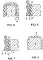
- Figure 5 which does not form part of the claimed invention, shows a syringe stopper comprised of an elastomer body 10, and a fluoropolymer barrier 20.
- the elastomer body 10 can be comprised of any elastomer suitable for the application, most notably rubbers constructed butyl, bromobutyl, chlorobutyl, silicone, nitrile, styrene butadiene, polychloroprene, ethylene propylene diene, fluorelastomers, or blends of any of the foregoing.
- the materials of the barrier 20 are chosen to provide low coefficient of friction, compliance, low extractables and leachables, good barrier properties as they relate to extractables and leachables from the elastomer body.
- the barrier (20) may comprise a single layer of densified ePTFE.
- Figure 8 which does not form part of the claimed invention, shows a syringe stopper comprised of an elastomer body, 10, and a barrier layer, 30.
- the elastomer body may comprise any of these previously mentioned materials.
- the barrier film may comprise densified expanded fluoropolymer, preferably densified ePTFE.
- a densified ePTFE film may be prepared in the manner described in US Patent No. 7,521,010 to Kennedy, et al is combined with an elastomer to construct a syringe stopper.
- the densified ePTFE film is thermoformed to make a preform. Thermoforming is done at process temperatures sufficiently above the nodal melt to ensure melt forming while preserving barrier and strength properties.
- the high strength expanded film allows for forming extremely thin barrier films.
- Barrier films can be made with thicknesses ranging from 0.5 micron to 20 microns. The films are preferentially less than 30 microns.
- the film can optionally be pre treated or post treated with chemical etching, plasma treating, corona, roughening or the like to improve bonding to the elastomer body.
- thermoformed, densified ePTFE preform can be combined with the elastomer body by injection molding, compression molding, priming and post laminating around an elastomer perform, or other suitable means.
- elastomers that can be used to form the elastomer body include silicone, butyl, nitrile, polyurethane, fluoroelastomers, styrene ethylene butadiene styrene elastomers, styrene butadiene rubbers, and the like.
- the barrier 20 may comprise a composite fluoropolymer film having a barrier layer 30 and a porous layer 40.
- the barrier layer 30 can be comprised of densified ePTFE, PTFE, fluorinated ethylene propylene (FEP), polyethylene, polypropylene, polyvinylidene fluoride, polyvinylfluoride, perfluoropropylevinylether, perfluoroalkoxy polymers, and the like.
- the porous layer 40 can be comprised of ePTFE or other porous expanded and advantageously fibralizing fluoropolymers (for example, ePTFE as taught in US 6,541,589 ).
- the ePTFE layers may advantageously be filled with an organic or inorganic material to provide color lubricity or other function.
- a barrier is constructed by coating or otherwise depositing a barrier polymer onto the porous expanded layer to create a composite film.
- a barrier polymer such as powdered PTFE onto the porous ePTFE surface in a coating process.
- the ePTFE support should be constructed to be thermally stable enough to allow heat treatment of the deposited fluoropolymer for the creation of a barrier or for bonding of the deposited layer to the porous ePTFE support.
- elastomer material may advantageously penetrate the porous structure of the barrier.
- Figure 6 which does not form part of the claimed invention, shows a cross-section of a stopper depicting the syringe barrel wall, 50, the barrier film, 30, the porous layer, 40, and the elastomer body, 10. Specifically, this figure shows a region of partial penetration 41 of the elastomer material into the porous structure, 40. Penetration of the elastomer material into the porous structure may improve the bond between elastomer and barrier.
- Figure 7 shows a cross-section of an embodiment of a syringe stopper according to the invention including the syringe barrel wall, 50, a barrier 41, and an elastomer body, 10.
- the barrier is comprised of a barrier layer, 30, and a porous layer, 40.
- the barrier layer comprises a coating deposited onto the porous layer 40.
- the barrier layer comprises a polymer at least partially imbibed into the porous layer 40, in a manner that creates a porous layer composite section 99.
- This porous layer composite section 99 may improve bonding of the barrier polymer to the porous layer.
- the porous composite section may also provide support for the barrier polymer to impart strength, toughness, compliance and stability which may be beneficial in both the forming process and in the application.
- the barrier layer 30 comprises an imbibed barrier polymer applied in a manner that allows leaves certain sections the porous layer exposed on the surface.
- the porous layer may be sufficiently exposed to allow the exposed sections to come in contact with the syringe wall, 50.
- the porous polymer is advantageously comprised of ePTFE or other suitable lubricious, expanded porous fluoropolymer. The exposed sections of fluoropolymer may reduce the coefficient of friction of the barrier film against the wall.
- a porous layer is disposed between the barrier layer surface and the elastomer of the stopper.
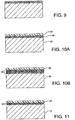
- the inventive stopper may advantageously include various degrees of penetration of barrier polymer into the porous material as shown in Figures 10B through 13 .
- Figure 10A is a cross-sectional view of the stopper, which does not form part of the claimed invention, showing the elastomer layer (10) and a composite layer comprising a fluoropolymeric barrier layer (30) and a porous ePTFE layer (40).
- the elastomeric material from layer (10) substantially fills the pores of the ePTFE layer (40).
- the barrier polymer (30) may substantially fill the porous structure (40), as in Figure 11 .
- the porous material (40) is filled to a substantially similar degree with barrier polymer (30) and elastomer (10), leaving few open pores in the porous structure as in Figure. 10B .
- both the barrier polymer and the elastomer partially fill the porous structure, while leaving some open pores between them as shown in Figure 12 .
- Other variations of penetration of elastomer and or barrier fluoropolymer may be readily apparent, one such variant shown in Figure 13 .
- Each may have advantages according to the specific application, with due consideration to the various desirable characteristics of the finished device, such as reduced friction, improved barrier properties, and improved sealing.
- the degree of penetration of either barrier polymer or elastomer may be controlled by any means known, but include variations in time, temperature, pressure, and porosity of the porous material.
- the porous material may, for example have a porosity that varies with depth.
- the barrier may comprise a composite of a densified ePTFE film and a thin layer of porous ePTFE bonded to the barrier layer film.
- a densified ePTFE film may be obtained as described in U.S. Patent No. 7,521,010 to Kennedy et al.
- the ePTFE / densified ePTFE composite may be combined in the manner described in US Patent No. 6,030,694 to Dolan, et al.
- a composite barrier comprises a layer of densified ePTFE film and a porous ePTFE layer.
- the porous ePTFE layer is constructed in a manner that it retains most of its porosity through thermoforming. It is also sufficiently compliant that it improves sealability against the syringe barrel wall. To accomplish this, at least a portion of the porous layer may remain sufficiently open after thermoforming and post compression molding with the elastomer. This open porosity allows some compressibility which may aid in the conformability and seal of the stopper to the surface.
- the thickness of the densified ePTFE film would be suitably tailored to the application with pre-thermoform thicknesses of less than 100 microns, more preferably, less than 50 microns, more preferably less than 30 microns. Additionally, the flexural rigidity of the composite film would need to be suitably tailored to ensure compliance and sealability while retaining sufficient strength for this application.
- the ePTFE porous layer would be preferably less than 150 microns thick. To improve performance as a bonding layer, the ePTFE porous layer should be made sufficiently open to allow for at least partial penetration of the elastomer into the porous (i.e. and fibrillated structure onto the surface of the nodes or fibrils) during elastomer forming.
- the composite barrier may be thermoformed at temperatures, rates and pressures suitable to allow the densified film to form to the shape of the female cavity of a stopper mold.
- the more porous ePTFE layer may be oriented toward the inside of the mold cavity, while the densified ePTFE barrier layer will be oriented toward the outer wall of the mold.
- the thermoforming can be done at temperature ranges suitable to form the ePTFE based film, without fracturing or otherwise disturbing the barrier provided by the densified ePTFE barrier layer. Suitable temperatures could be in the range of 330-400°C, more preferably 350-380°C at pressures suitable to form without fracturing the barrier layer, or substantially collapsing the porous layer.
- thermoformed barrier preform may be integrated with an elastomeric syringe stopper of the current invention by, for example, by injection molding or compression molding an elastomer like butyl rubber or silicone or Viton®.
- the porous ePTFE layer can be advantageously made stable to the elastomer injection or compression molding process, thereby maintaining some of its porous structure.
- the porous structure may improve the bond of the elastomer to the barrier. This may result in improved compliance for sealability, as the porous layer allows for some compressibility for better, low force sealing.
- a barrier can be made by forming a thin densified composite comprising a porous ePTFE layer and a thermoplastic barrier layer.
- a thermoplastic having a surface with a low coefficient of friction is preferred. Accordingly, fluoropolymer based thermoplastics such as FEP, PFA, THV may be applicable.
- a barrier according to this aspect may be an FEP/ePTFE laminate obtained by following the process taught in WO 94/13469 to Bacino . The barrier may be formed at process temperatures above the softening temperature or even above the melt of the FEP film in a female cavity mold.
- the composite barrier of ePTFE and FEP described may allow forming of surprisingly thin, strong barrier films.
- the ePTFE layer may act as a support during shape forming to allow thin barrier films.
- the porous ePTFE layer may also act as a reinforcement to the thermoplastic layer to maintain film strength and integrity of the barrier layer as described above, the ePTFE porous layer can also serve as a bonding layer when a portion of the ePTFE is allowed to remain porous and oriented toward the inside of the mold.
- a composite film with an elastomer can allow the porous portion of the ePTFE to be adhered to by partial penetration of the elastomer into the porous structure.
- the composite barrier film can be chemically modified by etching or plasma or physically modified by roughening, for example, to allow bonding to the elastomer.
- the ePTFE porous layer can be comprised of multiple layers of ePTFE, each having varying pore size and structure. This multi layer construction may facilitate control of the degree imbibing of the barrier polymer or the elastomer or to allow other desired properties.
- porous film portion of the expanded fluoropolymer layer can maintain its structure through thermoforming and post injection or compression molding of the elastomer. This allows for some of the advantages described above including improved compliance and sealability as well as improved bond between the barrier film and the elastomer body.
- composite barrier is made by laminating a ePTFE porous layer to a densified ePTFE barrier layer using a thin layer of an adhesive, for example, a fluoropolymer thermoplastic like PFA.
- a syringe stopper of the current invention can be made by combining composite barrier with an elastomer layer such that the thermoplastic bonds the densified ePTFE barrier layer and the porous ePTFE layer.
- the ePTFE porous layer of the composite barrier is bonded to the elastomer i.e. stopper material during the molding process.
- a composite film could be made by starting with a multilayer porous expanded fluoropolymer film and substantially densifying one or more of the porous layers.
- the porous layer may be densified by application of pressure during the molding or syringe insertion process.
- a porous expanded fluoropolymer film could be formed, then post applied to create a barrier layer.
- this could be done by choosing an ePTFE film of suitable deformation characteristics that it allows for deformation into the mold at relatively low temperatures (less than 200°C).
- a suitable ePTFE film might, for instance, have tensile properties demonstrating high elongation, or low modulus at the deformation temperature.
- the ePTFE film can be formed into the female mold cavity through a variety of means including through the use of air pressure, through the use of a male mold form, or other suitable means to allow forming of the ePTFE.
- One method would be to form such an ePTFE film during the injection or compression molding process.
- the ePTFE comprised the outermost layer of the syringe stopper.
- the pore structure, thickness, and other properties can be suitably tailored to allow controlled penetration of the elastomer into the expanded fluoropolymer layer.
- the elastomer is allowed to penetrate through the expanded fluoropolymer film, allowing for a composite structure of expanded fluoropolymer film and elastomer at the outer surface. If the outer surface is suitably dense and nodal, it can allow for significantly reduce friction relative to the elastomer itself.
- a preferred embodiment utilizes a stopper created using the aforementioned process of forming an ePTFE film in a female mold, then post imbibing a barrier onto the ePTFE's outermost surface.
- the ePTFE can be used to control the barrier thickness.
- a syringe stopper of the current embodiment could be comprised of a composite barrier comprised of multiple porous layers or multiple barrier layers or both.
- the properties of a composite barrier so constructed can be more suitably tailored to allow optimal compliance through the properties of the thin films while providing low surface friction against the barrel and adequate barrier properties to leachables, extractables and gas permeation.
- Another means of making the ePTFE syringe stopper with porous outer and creating a barrier layer would be to post densify the ePTFE with pressure and temperature.
- an improved tip cap for a syringe may be provided as a protective covering to a syringe needle. Accordingly, a tip cap may provide a seal to the end of the needle to prevent contamination of a medicament.
- a tip cap construction that minimizes leachable and extractable components is desirable.
- the tip cap must be readily removable. Moderate friction between the tip cap and needle is preferred.
- the tip cap therefore may be of construction similar to that of the syringe stopper.
- the barrier layer is positioned in the tip cap to be adjacent to the needle on final assembly.
- Each test syringe was attached to a variable pressure pump (Barnant Air Cadet-model 420-3901) by securing a 0.64 cm OD, 0.32 cm ID (1 ⁇ 4" OD, 1/8" ID) silicone tube to its tip (the tip was not fitted with a needle).
- the stopper assembly with the barrier film was positioned in the syringe to be at the bottom of its motion (closest to the tip).
- the pressure was slowly adjusted starting at 13.8 kPa (2 psi) and increasing about 6.9 kPa (1 psi) every 30 seconds until syringe stopper movement was initiated (away from tip).
- the pressure to initiate movement was noted as P break.
- the pressure was reduced to the lowest level that still allowed sliding. This pressure was noted as P sliding. All pressures were recorded in kPa (PSI).
- PSI kPa
- the same apparatus and setup as described above was then used to evaluate air leakage.
- the syringe stopper was attached to the pressure pump. However, in this test the stopper was moved to the topmost position within the syringe (farthest from the tip) and the syringe assembly was placed in a 2 Liter glass beaker filled with deionized water. The pressure was set to 20.7 kPa (3 psi). If no leaks were detected (any sign of visual bubble formation) after 5 minutes, the pressure was increased by 6.9 kPa (1 psi).
- FIG. 14 A schematic illustration of the test apparatus is shown in Figure 14 .
- the initial weight of the stopper was measured using a balance.
- the stopper (160) was loaded into the barrel (162) of a glass syringe.
- 1ml of Toluene (166) was introduced into the barrel through the luer port (164).
- the luer port was sealed using a tip cap.
- the entire apparatus was left under the lab hood for 5 hours at room temperature. After 5 hours, the Toluene was removed from the barrel using a syringe.
- the stopper was removed from the barrel using compressed air. Upon removal of the stopper, it was quickly dried using a Kimwipe® and immediately weighed using the balance. Lower the weight gain of the stopper compared to its initial weight, the more effective its function as a barrier. Less than 1 mg weight gain of the stopper may indicate an effective barrier.
- FIG. 15 describes a schematic of the test apparatus comprising a vent tube (170) meant for a 1mL standard stopper (as specified in ISO11040-5) and a plunger (172).
- the vent tube part of a SVH200 Semiautomatic Stoppering Machine from Groninger was used in this procedure.
- the apparatus was loaded into a universal testing machine capable of moving the plunger at a rate of 0.7 meters/sec.
- the stopper (174) was placed on to the top of the vent tube (170).
- the test was initiated by moving the plunger at a rate of 0.7 meters/sec to push the stopper through the vent tube.
- the test was complete when the stopper traversed the entire length of the vent tube.
- the washed syringe barrels and stoppers were allowed to dry for 5 days on an airhood to ensure complete evaporation of the hexane.
- Syringe stoppers were made by taking a densified ePTFE film and applying it to the stopper. Samples were made using these different film thicknesses. The films were first heated by a heat gun (Karl Leister, CH 6056-Hotwind S) set at 600°C at a distance of about 15.24-20.32 cm (6-8 inches) from the nozzle. The films were then drawn around the stopper in the presence of the heat (thereby using the stopper as a male plug or mold).
- a heat gun Karl Leister, CH 6056-Hotwind S
- the table below demonstrates the performance as measured by the breaking and sliding friction test and the air leak test of each wrapped stopper compared to a silicone oil control. It can be seen that the thin densified ePTFE films showed better performance than the relatively thicker films with respect to providing an airtight seal. This was in part due to unavoidable wrinkling around the stopper contours in this process.
- a barrier was created from a single densified ePTFE film 43.2 - 45.7 ⁇ m (1.7 - 1.8 mil) thick, which was obtained by the process described in US Patent 7,521,010 to Kennedy, et al.
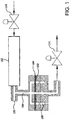
- the film (104) was placed in the thermoforming equipment as depicted in Figure 1 using the mold depicted in Figure 2 .
- the thermoforming equipment (100) uses hot air to heat the mold (200), and the pressure drop through the apparatus supplies the force to form the material.
- the mold has round cavities (202 a-d) having different dimensions. One of 9.65 mm (0.380 inches), one of 9.45 mm (0.372 inches), one of 9.27 mm (0.365 inches), and one of 9.09 mm (0.358 inches.
- the bottom portion of the cavities have a rounded corner (203) with a radius of 2.01 mm (0.079 inches), a side straight wall 205 of 4.77 mm (0.188 inch) height, and contain a 5.11 mm (0.201 inch) wide, 2 micron porous stainless steel disc (204) at its bottom most point.
- a pressure of 34.5 kPa (5 psi) was applied.
- the heater on the hot air system (102) (Osram Sylvania 6000W, 240V, 25A) was activated using a setpoint of 385°C as measured by the thermocouple (106) above the mold. Once a temperature of 360°C was reached below the mold cavities, as measured by the bottom thermocouple (108), the system was held for 5 minutes. Pressure was then increased by increasing the inlet air flow using the hot air system inlet valve (110). The pressure was increased at a rate of approximately 20.7 kPa/minute (3 psi/minute) from 34.5 kPa (5 psi)to 89.6 kPa (13 psi).
- the pressure was increased at approximately 6.9 kPa/minute (1 psi/minute) up to 124.10 kPa (18 psi). This pressure was sufficient to form the densified ePTFE sheet.
- the sample was held at this pressure for 5 minutes, and then the heater was deactivated allowing the mold and film to cool.
- the mold was allowed to cool to below 50°C, as measured by the bottom thermocouple, before removing the sample.
- Any technique suitable for heating both the material and the mold as well as adding the air pressure to form the material will suffice.
- the mold may be simply bolted together and placed in an oven or heated press with an air line to supply the pressure.
- Other processes known for thermoforming, bladder forming or vacuum forming may also be used.
- sample cavities were filled with a 10% by weight solution of the elastomer in MEK and allowed enough time to dry so that a substantial amount of the solvent was evaporated.
- Each cavity was loaded with 1-1.5 grams of elastomer (Viton GF-600S from DuPont compounded with varox D8PH and Diak 7 and processed to a crumb (304) by Eagle Elastomer Inc., Cuyahoga Falls, Ohio).
- the mold (306) along with the above thermoformed densified ePTFE sheet was loaded into a press with both platens (300, 302) preheated to 100°C.
- a 0.25 mm (10 mil) Aluminum sheet (312) was placed on the lower platen (302).
- a Kapton sheet (308) and a steel caul plate (310) were placed below the upper press platen (300) to provide uniform pressure.
- the sample was heated under no pressure for 45 minutes, and then compressed under a force of 3628.7 kg (8000) lbs.
- the platens were slowly closed and temperature based set points were used in the following press cycle:
- Samples were then cut from the release sheet using a razor blade, affixed to a stopper rod using an acrylic adhesive (3M Scotch-Weld Structural Adhesive DP-8005) and installed within a standard 1 mL (1cc) glass syringe barrel free of silicone oil, and tested.
- an acrylic adhesive (3M Scotch-Weld Structural Adhesive DP-8005)
- a sample was prepared in a manner similar to Reference Example 2 except that the densified ePTFE barrier was formed to shape using a faster pressure ramp rate.
- the procedure of Example 2 was followed except that a pressure ramp rate of approximately 20.7 kPa/minute (3 psi/minute) from 34.5 kPa - 124.1 kPa (5 psi to 18 psi)was chosen. This ramp rate was obtained by closing only the exit air valve (112).
- This molding procedure resulted in a barrier film with milky appearance, which may indicate that there was some porosity induced in the material by the speed of the forming process.
- the mold cavity was then filled with elastomer, molded and attached to a syringe stopper according to the process described in Reference Example 2. After insertion into a glass syringe barrel the sample was tested.
- a sample was prepared in a manner similar to that described in Reference Example 2, except that one surface of the densified ePTFE barrier material was textured before it was thermoformed.
- One side of the densified ePTFE material was deformed using a coarse glass bead sandblaster.
- the sandblaster nozzle was set to 103.4 kPa (15 psi) and held approximately 22.9 cm (9 inches)away from the sample, which was affixed to a cardboard backer.
- the sandblaster was passed 5 times over the entire surface of the sample. This process resulted in significant mechanical deformation on one side of the film which increased the apparent surface roughness.
- the barrier material was placed in the mold with the roughened side up so that it would be oriented towards the elastomer.
- the mold cavity was then filled with elastomer, molded and attached to a syringe stopper according to the process described in Reference Example 2. After insertion into a glass syringe barrel, the sample was tested.
- a sample was prepared similar to Reference Example 1 except that the densified ePTFE barrier material exposed to a plasma treatment after thermoforming. The material was left in the mold and placed in a plasma vacuum chamber with a 90/10 mix of He/H 2 and an exposure time of 10 minutes. This sample was not coated with an elastomer solution before compression molding. Otherwise the procedure of Reference Example 2 were followed.
- the mold cavity was then filled with elastomer, molded and attached to a syringe stopper.
- a sample was prepared in a manner similar to Reference Example 2, except that an ePTFE/PFA composite film was used as a barrier.
- the barrier was obtained in a manner similar to that described in Example 2 of WO 94/13469 to Bacino .
- the resulting barrier is an ePTFE material with PFA on one of its side surfaces.
- the barrier material was placed in the mold with the PFA side of the composite facing upwards, such that after thermoforming the PFA would be oriented towards the inside of the mold.
- the thermoforming process followed that of Example 2 except that the heater setpoint was 295°C and the mold cavity setpoint was approximately 275°C.
- the pressure ramp rate in the molding process was approximately 79.3 kPa/minute (11.5 psi/min) from 34.5 to 124.1 kPa (5 to 18 psi).
- the composite material was held at 124.1 kPa (18 psi) for approximately 15 seconds before cooling. After the sample was removed from the mold it was inverted so that the ePTFE layer was facing inward.
- a sample was prepared in a manner similar to Reference Example 2 except that the barrier was an ePTFE/densified ePTFE composite.
- the barrier was prepared according to the methods disclosed in U.S. Pat. No. 6,030,694 to Dolan .
- the material was oriented in the mold with the ePTFE side of the composite downward, the molded sample was inverted after thermoforming so that the ePTFE layer was facing inward.
- each cavity was a straight cylinder of 6.40 mm (0.252 inch) height and had a stainless steel porous disc making up the bottom of the cavity.
- Another example was constructed using an ePTFE/FEP composite obtained using the procedure described in Bacino.
- the film was placed over a mold cavity and formed by compression molding.
- a single cavity mold was used having a profile depicted in Figure 4 .
- the mold had a primary diameter of 1.25 cm (0.49 inches).
- the barrier material was obtained using the procedure described in Bacino.
- FEP 100 A layer of FEP about 12.7 ⁇ m (0.5 mils) in thickness (FEP 100, DuPont) was laminated to a layer of densified expanded PTFE film [thickness: 25.4 ⁇ m (1mil); tensile strength: 90.50 MPa (13.85ksi) (longitudinal), 95.84 MPa (13.9ksi) (transverse); modulus: 136.52 MPa (19.8ksi) (longitudinal), 142.72 MPa (20.7ksi) (transverse); strain to break: 425% (longitudinal), 425% (transverse)].
- the two layers were stacked on top of each other in a pin frame and heating to 380°C in an oven for 15 minutes.
- a layer of porous expanded PTFE [thickness: 27.5 micrometers, matrix tensile strength: 66.8MPa (longitudinal), 75.8MPa (transverse), strain to break: 131% (longitudinal), 91% (transverse), bubble point: 155.82 kPa (22.6psi)] was placed on the densified ePTFE-FEP laminate such that the porous expanded PTFE layer faced the FEP layer in the laminate.
- These three layers were placed between two smooth metal plates, the plates were clamped to a clamping pressure of about 6.89 kPa (1 psi). The plates were then placed in an oven at 305°C for 15 minutes.
- the resulting three layer composite material (densified ePTFE - FEP - porous ePTFE) was then cooled to about 40°C.
- This composite material was then thermoformed using heat and vacuum to create a pre-form.
- the pre-form was constructed by heating the composite to a sufficiently high temperature and then drawing the composite over a male plug using differential pressure.
- the composite material was loaded into the thermoforming apparatus such that the densified ePTFE layer faced the plug.
- the composite was heated using a hot air gun (Steinel HG2310) with air exit temperature of 380°C by placing the gun about 5mm away from the surface of the composite. After 5 seconds, the film was subjected to a vacuum of -85kPa. The composite was continued to be heated for another 15 seconds and cooled to about 40°C under vacuum.
- the resulting pre-form sample was then inverted and then placed into a rubber molding cavity charged with 3.5 grams of elastomer (50 Durometer halobutyl rubber), and the stopper was formed by compression molding.
- the mold was built to geometry specified for 1mL standard plunger per the ISO standard ISO11040-5:2001(E), with an additional 5% shrinkage factor incorporated.
- the cavity was loaded in a press with both platens preheated to 120°C.
- the platens were closed to 25.17 tonne (55,500 lbs) (about 60.0 MPa (8700 psi)total internal pressure).
- the platens were then heated at 180°C for 5 minutes and then cooled under pressure to 40°C.
- the pressure was released and the stopper was ejected.
- the resulting stopper was washed using a detergent and triple rinsed with de-ionized water. Stopper samples were then cut from the release sheet using a razor blade. They were subjected to two 30 minute cycles in an autoclave at 121°C. The static and dynamic force on the stopper was measured to be 2.5N and 2.1N respectively.
- the weight gain of the stopper after the Toluene Exposure test was 0 mg, indicating that the stopper functioned as an effective barrier. Further, the same stopper was subjected to the vent tube placement test and then the Toluene exposure test was repeated. The weight gain was still 0 mg, indicative of superior barrier function of the stopper. The stopper was also tested for leaks using the air leak test and no leak was detected. Comparative Example A - Commercial siliconized butyl stopper made for 1 mL (1cc) single dose glass prefilled syringe.
Claims (7)
- Bouchon de seringue comprenant :un corps élastomère (10) ;un film barrière (41) positionné sur ledit corps élastomère (10) et comprenant un fluoropolymère expansé (40) ; etun polymère barrière (30) au moins partiellement imbibé dans ledit fluoropolymère expansé (40).
- Bouchon de seringue selon la revendication 1, ledit polymère barrière (30) étant entièrement imbibé dans ledit fluoropolymère expansé (40).
- Bouchon de seringue selon la revendication 1 ou 2, ledit fluoropolymère expansé comprenant un polytétrafluoroéthylène expansé.
- Bouchon de seringue selon l'une quelconque des revendications 1 à 3, ledit polymère barrière étant choisi parmi le polytétrafluoroéthylène, l'éthylène-propylène fluoré, le polyéthylène, le polypropylène, le difluorure de polyvinylidène, le fluorure de polyvinyle, l'éther perfluoropropylevinyle et le perfluoroalkoxy.
- Bouchon de seringue selon l'une quelconque des revendications 1 à 4, ledit corps élastomère étant constitué d'un caoutchouc constitué de butyle, bromobutyle, chlorobutyle, silicone, nitrile, styrène butadiène, polychloroprène, éthylène propylène-diène, fluoroélastomères et leurs mélanges.
- Seringue comprenant le bouchon de seringue selon l'une quelconque des revendications 1 à 5.
- Seringue selon la revendication 6, ladite seringue étant sans lubrifiant.
Priority Applications (2)
| Application Number | Priority Date | Filing Date | Title |
|---|---|---|---|
| EP19179490.8A EP3556412B1 (fr) | 2009-10-29 | 2010-10-29 | Piston de seringue revêtu d'eptfe |
| EP17195666.7A EP3308816B1 (fr) | 2009-10-29 | 2010-10-29 | Piston de seringue revêtu de ptfe expansé densifié |
Applications Claiming Priority (3)
| Application Number | Priority Date | Filing Date | Title |
|---|---|---|---|
| US25615609P | 2009-10-29 | 2009-10-29 | |
| EP10776234.6A EP2493534B1 (fr) | 2009-10-29 | 2010-10-29 | Piston de seringue revêtu de eptfe |
| PCT/US2010/054750 WO2011059823A1 (fr) | 2009-10-29 | 2010-10-29 | Bouchon de seringue revêtu de ptfe expansé |
Related Parent Applications (1)
| Application Number | Title | Priority Date | Filing Date |
|---|---|---|---|
| EP10776234.6A Division EP2493534B1 (fr) | 2009-10-29 | 2010-10-29 | Piston de seringue revêtu de eptfe |
Related Child Applications (3)
| Application Number | Title | Priority Date | Filing Date |
|---|---|---|---|
| EP19179490.8A Division EP3556412B1 (fr) | 2009-10-29 | 2010-10-29 | Piston de seringue revêtu d'eptfe |
| EP17195666.7A Division EP3308816B1 (fr) | 2009-10-29 | 2010-10-29 | Piston de seringue revêtu de ptfe expansé densifié |
| EP17195666.7A Division-Into EP3308816B1 (fr) | 2009-10-29 | 2010-10-29 | Piston de seringue revêtu de ptfe expansé densifié |
Publications (2)
| Publication Number | Publication Date |
|---|---|
| EP3207953A1 EP3207953A1 (fr) | 2017-08-23 |
| EP3207953B1 true EP3207953B1 (fr) | 2019-06-12 |
Family
ID=43530278
Family Applications (6)
| Application Number | Title | Priority Date | Filing Date |
|---|---|---|---|
| EP19179490.8A Active EP3556412B1 (fr) | 2009-10-29 | 2010-10-29 | Piston de seringue revêtu d'eptfe |
| EP17161694.9A Active EP3202444B1 (fr) | 2009-10-29 | 2010-10-29 | Piston de seringue revêtu de eptfe |
| EP17161692.3A Active EP3207953B1 (fr) | 2009-10-29 | 2010-10-29 | Piston de seringue revêtu d'eptfe |
| EP20176199.6A Pending EP3725348A1 (fr) | 2009-10-29 | 2010-10-29 | Capuchon de seringue revêtu d'eptfe |
| EP17195666.7A Active EP3308816B1 (fr) | 2009-10-29 | 2010-10-29 | Piston de seringue revêtu de ptfe expansé densifié |
| EP10776234.6A Active EP2493534B1 (fr) | 2009-10-29 | 2010-10-29 | Piston de seringue revêtu de eptfe |
Family Applications Before (2)
| Application Number | Title | Priority Date | Filing Date |
|---|---|---|---|
| EP19179490.8A Active EP3556412B1 (fr) | 2009-10-29 | 2010-10-29 | Piston de seringue revêtu d'eptfe |
| EP17161694.9A Active EP3202444B1 (fr) | 2009-10-29 | 2010-10-29 | Piston de seringue revêtu de eptfe |
Family Applications After (3)
| Application Number | Title | Priority Date | Filing Date |
|---|---|---|---|
| EP20176199.6A Pending EP3725348A1 (fr) | 2009-10-29 | 2010-10-29 | Capuchon de seringue revêtu d'eptfe |
| EP17195666.7A Active EP3308816B1 (fr) | 2009-10-29 | 2010-10-29 | Piston de seringue revêtu de ptfe expansé densifié |
| EP10776234.6A Active EP2493534B1 (fr) | 2009-10-29 | 2010-10-29 | Piston de seringue revêtu de eptfe |
Country Status (8)
| Country | Link |
|---|---|
| US (1) | US8722178B2 (fr) |
| EP (6) | EP3556412B1 (fr) |
| JP (2) | JP2013509270A (fr) |
| CN (1) | CN102725012B (fr) |
| AU (1) | AU2010319826B2 (fr) |
| CA (1) | CA2778978C (fr) |
| HK (1) | HK1248628A1 (fr) |
| WO (1) | WO2011059823A1 (fr) |
Families Citing this family (82)
| Publication number | Priority date | Publication date | Assignee | Title |
|---|---|---|---|---|
| EP2253735B1 (fr) | 2009-05-13 | 2017-11-22 | SiO2 Medical Products, Inc. | Traitement de récipient |
| US9458536B2 (en) | 2009-07-02 | 2016-10-04 | Sio2 Medical Products, Inc. | PECVD coating methods for capped syringes, cartridges and other articles |
| CN102725012B (zh) | 2009-10-29 | 2016-01-06 | W.L.戈尔及同仁股份有限公司 | 涂覆膨胀型ptfe的注射器塞 |
| US10471212B2 (en) | 2009-10-29 | 2019-11-12 | W. L. Gore & Associates, Inc. | Silicone free drug delivery devices |
| US9597458B2 (en) * | 2009-10-29 | 2017-03-21 | W. L. Gore & Associates, Inc. | Fluoropolymer barrier materials for containers |
| US11624115B2 (en) | 2010-05-12 | 2023-04-11 | Sio2 Medical Products, Inc. | Syringe with PECVD lubrication |
| US11612697B2 (en) | 2010-10-29 | 2023-03-28 | W. L. Gore & Associates, Inc. | Non-fluoropolymer tie layer and fluoropolymer barrier layer |
| US9878101B2 (en) | 2010-11-12 | 2018-01-30 | Sio2 Medical Products, Inc. | Cyclic olefin polymer vessels and vessel coating methods |
| US9272095B2 (en) | 2011-04-01 | 2016-03-01 | Sio2 Medical Products, Inc. | Vessels, contact surfaces, and coating and inspection apparatus and methods |
| WO2012142479A1 (fr) * | 2011-04-15 | 2012-10-18 | W.L. Gore & Associates, Inc. | Méthode de réduction des frottements entre les composants d'une seringue |
| CN102260378B (zh) * | 2011-05-06 | 2013-03-20 | 广东生益科技股份有限公司 | 复合材料、用其制作的高频电路基板及其制作方法 |
| WO2012160595A1 (fr) * | 2011-05-20 | 2012-11-29 | 有限会社コーキ・エンジニアリング | Film biseauté pour recouvrir la surface d'un bouchon utilisé à des fins médicales, bouchon utilisé à des fins médicales utilisant le film, seringue pré-remplie utilisant le bouchon et procédé de production du film |
| AU2015204395B2 (en) * | 2011-05-27 | 2017-02-23 | W. L. Gore & Associates, Inc. | Fluoropolymer barrier materials for containers |
| WO2012167031A1 (fr) * | 2011-06-03 | 2012-12-06 | W. L. Gore & Associates, Inc. | Condensateur en film de polytétrafluoroéthylène |
| US11116695B2 (en) | 2011-11-11 | 2021-09-14 | Sio2 Medical Products, Inc. | Blood sample collection tube |
| US10189603B2 (en) | 2011-11-11 | 2019-01-29 | Sio2 Medical Products, Inc. | Passivation, pH protective or lubricity coating for pharmaceutical package, coating process and apparatus |
| EP2841128A4 (fr) * | 2012-04-23 | 2015-11-25 | Zogenix Inc | Fermetures à piston pour capsules d'administration de médicament |
| EP2846755A1 (fr) | 2012-05-09 | 2015-03-18 | SiO2 Medical Products, Inc. | Enrobage protecteur en saccharide pour conditionnement pharmaceutique |
| EP2857091B1 (fr) | 2012-05-30 | 2017-08-16 | Mitsui Chemicals, Inc. | ;dispositif de mélange de trois composants, procédé et kit d'adhésif à trois composants |
| PT3536310T (pt) | 2012-06-01 | 2021-07-14 | Novartis Ag | Seringa |
| JOP20200175A1 (ar) | 2012-07-03 | 2017-06-16 | Novartis Ag | حقنة |
| US9283072B2 (en) | 2012-07-25 | 2016-03-15 | W. L. Gore & Associates, Inc. | Everting transcatheter valve and methods |
| JP6509734B2 (ja) | 2012-11-01 | 2019-05-08 | エスアイオーツー・メディカル・プロダクツ・インコーポレイテッド | 皮膜検査方法 |
| EP2920567B1 (fr) | 2012-11-16 | 2020-08-19 | SiO2 Medical Products, Inc. | Procédé et appareil pour détecter des caractéristiques d'intégrité de revêtement de barrière rapide |
| CA2892294C (fr) | 2012-11-30 | 2021-07-27 | Sio2 Medical Products, Inc. | Controle de l'uniformite de depot chimique en phase vapeur active par plasma (pecvd) sur des seringues medicales, des cartouches et analogues |
| US9764093B2 (en) | 2012-11-30 | 2017-09-19 | Sio2 Medical Products, Inc. | Controlling the uniformity of PECVD deposition |
| US9968443B2 (en) | 2012-12-19 | 2018-05-15 | W. L. Gore & Associates, Inc. | Vertical coaptation zone in a planar portion of prosthetic heart valve leaflet |
| US9101469B2 (en) | 2012-12-19 | 2015-08-11 | W. L. Gore & Associates, Inc. | Prosthetic heart valve with leaflet shelving |
| US10966820B2 (en) | 2012-12-19 | 2021-04-06 | W. L. Gore & Associates, Inc. | Geometric control of bending character in prosthetic heart valve leaflets |
| US9144492B2 (en) | 2012-12-19 | 2015-09-29 | W. L. Gore & Associates, Inc. | Truncated leaflet for prosthetic heart valves, preformed valve |
| US10039638B2 (en) | 2012-12-19 | 2018-08-07 | W. L. Gore & Associates, Inc. | Geometric prosthetic heart valves |
| WO2014134577A1 (fr) | 2013-03-01 | 2014-09-04 | Sio2 Medical Products, Inc. | Prétraitement par plasma ou par dépôt chimique en phase vapeur pour kit pharmaceutique lubrifié, procédé de revêtement et appareil |
| US9937099B2 (en) | 2013-03-11 | 2018-04-10 | Sio2 Medical Products, Inc. | Trilayer coated pharmaceutical packaging with low oxygen transmission rate |
| KR102167557B1 (ko) | 2013-03-11 | 2020-10-20 | 에스아이오2 메디컬 프로덕츠, 인크. | 코팅된 패키징 |
| EP2971227B1 (fr) | 2013-03-15 | 2017-11-15 | Si02 Medical Products, Inc. | Procede de revetement. |
| WO2014163645A1 (fr) * | 2013-04-05 | 2014-10-09 | West Pharmaceutical Services, Inc. | Piston de seringue pharmaceutique |
| EP3055007B1 (fr) | 2013-10-07 | 2020-12-02 | SiO2 Medical Products, Inc. | Pistons convertibles, pistons recouverts d'un film et ensembles seringues associés |
| CN105813672B (zh) | 2013-10-28 | 2023-10-27 | 贝克顿·迪金森公司 | 具有低松脱和持续力的注射器组件的无泄漏塞子 |
| US11066745B2 (en) | 2014-03-28 | 2021-07-20 | Sio2 Medical Products, Inc. | Antistatic coatings for plastic vessels |
| US10314697B2 (en) | 2014-08-18 | 2019-06-11 | W. L. Gore & Associates, Inc. | Frame with integral sewing cuff for prosthetic valves |
| CN107106782B (zh) | 2014-09-10 | 2020-10-23 | Sio2医药产品公司 | 三位置柱塞、涂膜的柱塞和相关注射器组件 |
| US9827094B2 (en) | 2014-09-15 | 2017-11-28 | W. L. Gore & Associates, Inc. | Prosthetic heart valve with retention elements |
| CN107635527B (zh) | 2015-03-10 | 2021-04-23 | 里珍纳龙药品有限公司 | 无菌刺穿系统和方法 |
| JP6968050B2 (ja) | 2015-07-14 | 2021-11-17 | エスアイオーツー・メディカル・プロダクツ・インコーポレイテッド | 切り替え可能なプランジャー、および医療用筒内でのその組み立て方法 |
| CA2995225C (fr) | 2015-08-18 | 2023-08-29 | Sio2 Medical Products, Inc. | Conditionnement pharmaceutique et autre presentant un faible taux de transmission d'oxygene |
| FR3041334B1 (fr) * | 2015-09-21 | 2020-02-14 | Disposable-Lab | Procede d'obturation d'un contenant comportant au moins un bouchon, notamment une carpule, moyens d'insertion et ligne d'obturation associee |
| AU2016356717B2 (en) * | 2015-11-18 | 2022-09-29 | Sio2 Medical Products, Inc. | Pharmaceutical package for ophthalmic formulations |
| US10471211B2 (en) | 2016-01-15 | 2019-11-12 | W. L. Gore & Associates, Inc. | Medical delivery device with laminated stopper |
| US10369292B2 (en) * | 2016-01-15 | 2019-08-06 | W. L. Gore & Associates, Inc. | Syringe plunger assemblies |
| US10286151B2 (en) | 2016-02-26 | 2019-05-14 | West Pharma. Services IL, Ltd. | Plunger with reduced leakage during storage |
| AU2017256308A1 (en) * | 2016-04-25 | 2018-12-06 | Terumo Kabushiki Kaisha | Syringe barrel for pre-filled syringe, syringe system, and pre-filled syringe |
| WO2017209800A1 (fr) | 2016-05-31 | 2017-12-07 | Sio2 Medical Products, Inc. | Pistons convertibles et leurs procédés d'assemblage dans un cylindre médical |
| USD870278S1 (en) | 2017-01-13 | 2019-12-17 | Sio2 Medical Products, Inc. | Syringe plunger assembly |
| US10493207B2 (en) | 2017-02-27 | 2019-12-03 | W. L. Gore & Associates, Inc. | Medical delivery devices having low lubricant syringe barrels |
| BR112019020705A2 (pt) | 2017-05-05 | 2020-05-12 | Regeneron Pharmaceuticals, Inc. | Autoinjetor |
| US10058658B1 (en) * | 2017-05-26 | 2018-08-28 | Precision Polymer Products, Inc. | Film faced articles and methods of manufacturing the same |
| CN111182856B (zh) | 2017-09-12 | 2022-04-29 | W.L.戈尔及同仁股份有限公司 | 用于假体瓣膜的瓣叶框架附连件 |
| CN115024861A (zh) | 2017-09-27 | 2022-09-09 | W.L.戈尔及同仁股份有限公司 | 具有机械联接的瓣叶的假体瓣膜 |
| CA3178271A1 (fr) | 2017-09-27 | 2019-04-04 | W.L. Gore & Associates, Inc. | Valvule prothetique a cadre extensible et systemes et procedes associes |
| CA3078699C (fr) | 2017-10-13 | 2023-10-10 | W.L. Gore & Associates, Inc. | Valvule prothetique telescopique et systeme de pose |
| JP7227240B2 (ja) | 2017-10-31 | 2023-02-21 | ダブリュ.エル.ゴア アンド アソシエイツ,インコーポレイティド | 人工心臓弁 |
| US11154397B2 (en) | 2017-10-31 | 2021-10-26 | W. L. Gore & Associates, Inc. | Jacket for surgical heart valve |
| AU2018362079B2 (en) | 2017-10-31 | 2021-09-16 | Edwards Lifesciences Corporation | Medical valve and leaflet promoting tissue ingrowth |
| WO2019089135A1 (fr) | 2017-10-31 | 2019-05-09 | W. L. Gore & Associates, Inc. | Systèmes de déploiement par transcathéter et procédés associés |
| CN114953652A (zh) | 2017-12-15 | 2022-08-30 | 西部制药服务有限公司 | 光滑膜层压弹性体制品 |
| US11614381B2 (en) | 2018-02-09 | 2023-03-28 | Takeda Pharmaceutical Company Limited | Syringe screening device |
| CN111902176B (zh) * | 2018-03-06 | 2022-09-13 | W.L.戈尔及同仁股份有限公司 | 具有低润滑剂疏水注射器筒的医疗递送设备 |
| EP4039295A1 (fr) | 2018-04-24 | 2022-08-10 | W. L. Gore & Associates, Inc. | Dispositifs d'administration médicale à perméation d'oxygène inhibée |
| FR3082729A1 (fr) * | 2018-06-26 | 2019-12-27 | Laboratoire Francais Du Fractionnement Et Des Biotechnologies | Conditions de stockage d'une composition de proteines comprenant du tensioactif et evolution de la teneur en tensioactif |
| EP3850038B1 (fr) | 2018-09-11 | 2022-12-21 | West Pharmaceutical Services, Inc. | Composants en élastomère contenant des agents de traçage |
| USD926322S1 (en) | 2018-11-07 | 2021-07-27 | W. L. Gore & Associates, Inc. | Heart valve cover |
| SG11202105384TA (en) * | 2018-11-27 | 2021-06-29 | Gore & Ass | A method of inserting a lubricant free stopper into a lubricant free barrel or a lubricant free cartridge tube and a system for assembling same |
| WO2020118275A1 (fr) | 2018-12-07 | 2020-06-11 | Abrams Robert S | Systèmes de seringues et de joints améliorés |
| US11497601B2 (en) | 2019-03-01 | 2022-11-15 | W. L. Gore & Associates, Inc. | Telescoping prosthetic valve with retention element |
| KR20230109676A (ko) * | 2020-11-16 | 2023-07-20 | 더블유.엘. 고어 앤드 어소시에이트스, 인코포레이티드 | 지방산 입자가 없는 제형, 방법, 및 사전 충전형 주사 장치 |
| CN117440846A (zh) * | 2021-04-29 | 2024-01-23 | 贝克顿·迪金森公司 | 用于注射器塞和容器密闭系统应用的具有减少的药物效力损失的橡胶组分 |
| AU2021461550A1 (en) | 2021-08-27 | 2024-02-22 | W. L. Gore & Associates, Inc. | Formation of injector device stopper features |
| WO2023027725A1 (fr) | 2021-08-27 | 2023-03-02 | W. L. Gore & Associates, Inc. | Remodelage de caractéristiques de butoir de dispositif d'injection |
| CA3227720A1 (fr) | 2021-08-27 | 2023-03-02 | W. L. Gore & Associates, Inc. | Modification de surface de composant de dispositif d'injecteur |
| CN117881445A (zh) | 2021-08-27 | 2024-04-12 | W.L.戈尔及同仁股份有限公司 | 具有可激活层的注入器装置止挡件 |
| USD1007676S1 (en) | 2021-11-16 | 2023-12-12 | Regeneron Pharmaceuticals, Inc. | Wearable autoinjector |
| WO2023168118A1 (fr) | 2022-03-04 | 2023-09-07 | Sio2 Medical Products, Inc. | Systèmes de seringues et de joints améliorés |
Family Cites Families (31)
| Publication number | Priority date | Publication date | Assignee | Title |
|---|---|---|---|---|
| GB399336A (en) | 1932-11-21 | 1933-10-05 | Josef Schoene | Device for the sterilization of injection-syringes by means of boiling water and steam |
| SE392582B (sv) * | 1970-05-21 | 1977-04-04 | Gore & Ass | Forfarande vid framstellning av ett porost material, genom expandering och streckning av en tetrafluoretenpolymer framstelld i ett pastabildande strengsprutningsforfarande |
| US4781693A (en) * | 1983-09-02 | 1988-11-01 | Minntech Corporation | Insulin dispenser for peritoneal cavity |
| EP0375778B1 (fr) * | 1987-06-19 | 1993-09-08 | Terumo Kabushiki Kaisha | Instrument medical et production de cet instrument |
| JPS6485665A (en) | 1987-06-19 | 1989-03-30 | Terumo Corp | Medical instrument and its preparation |
| JPH0534669Y2 (fr) * | 1988-03-16 | 1993-09-02 | ||
| US5431310A (en) * | 1988-10-07 | 1995-07-11 | Ryder International Corporation | Liquid dispenser nozzle assembly |
| US4964866A (en) | 1989-11-22 | 1990-10-23 | Becton, Dickinson And Company | Needle sheath assembly |
| US5112664A (en) * | 1990-11-30 | 1992-05-12 | W. L. Gore & Associates, Inc. | Shielded gasket assembly |
| US5279606A (en) * | 1991-08-28 | 1994-01-18 | Habley Medical Technology Corporation | Non-reactive composite sealing barrier |
| US5207983A (en) | 1992-01-29 | 1993-05-04 | Sterling Winthrop Inc. | Method of terminal steam sterilization |
| US5374473A (en) * | 1992-08-19 | 1994-12-20 | W. L. Gore & Associates, Inc. | Dense polytetrafluoroethylene articles |
| AU4408693A (en) | 1992-12-10 | 1994-07-04 | W.L. Gore & Associates, Inc. | Composite article |
| EP0737283B1 (fr) | 1994-10-31 | 2001-10-31 | W.L. Gore & Associates, Inc. | Materiau au polytetrafluoroethylene en feuille rigide |
| US5868704A (en) * | 1995-09-18 | 1999-02-09 | W. L. Gore & Associates, Inc. | Balloon catheter device |
| US5596814A (en) * | 1995-11-06 | 1997-01-28 | W. L. Gore & Associates, Inc. | Vented vial stopper for processing freeze-dried products |
| JP3387775B2 (ja) | 1997-05-22 | 2003-03-17 | 株式会社大協精工 | 注射器用密封栓及びプレフィルド注射器 |
| AU9783498A (en) * | 1997-10-03 | 1999-04-27 | Gore Enterprise Holdings, Inc. | An expanded ptfe covered space-filling implant |
| US6331351B1 (en) * | 1999-09-22 | 2001-12-18 | Gore Enterprise Holdings, Inc. | Chemically active filter material |
| DE50107279D1 (de) | 2000-02-18 | 2005-10-06 | Eco2 Sa Mezzovico | Autoklav zur präzisionsreinigung von stücken und verwendung des autoklavs |
| JP2002089717A (ja) | 2000-09-14 | 2002-03-27 | Terumo Corp | ガスケット |
| US6541589B1 (en) | 2001-10-15 | 2003-04-01 | Gore Enterprise Holdings, Inc. | Tetrafluoroethylene copolymer |
| US20030211264A1 (en) | 2002-05-09 | 2003-11-13 | Farnsworth Ted Ray | Expanded polytetrafluoroethylene (ePTFE)-reinforced perfluoroelastomers (FFKM) |
| US20040157035A1 (en) * | 2003-02-10 | 2004-08-12 | Guizzetti Allen R. | Low permeation gaskets |
| US20050238872A1 (en) | 2004-04-23 | 2005-10-27 | Kennedy Michael E | Fluoropolymer barrier material |
| US8637144B2 (en) | 2007-10-04 | 2014-01-28 | W. L. Gore & Associates, Inc. | Expandable TFE copolymers, method of making, and porous, expended articles thereof |
| EP2223677B1 (fr) | 2007-12-26 | 2018-08-22 | Daikyo Seiko, LTD. | Moulages en caoutchouc |
| US20090196798A1 (en) * | 2008-02-06 | 2009-08-06 | Robert Sassa | Barrier with Low Extractables and Resealing Properties |
| CN102725012B (zh) | 2009-10-29 | 2016-01-06 | W.L.戈尔及同仁股份有限公司 | 涂覆膨胀型ptfe的注射器塞 |
| US9597458B2 (en) | 2009-10-29 | 2017-03-21 | W. L. Gore & Associates, Inc. | Fluoropolymer barrier materials for containers |
| WO2012142479A1 (fr) | 2011-04-15 | 2012-10-18 | W.L. Gore & Associates, Inc. | Méthode de réduction des frottements entre les composants d'une seringue |
-
2010
- 2010-10-29 CN CN201080060456.7A patent/CN102725012B/zh active Active
- 2010-10-29 AU AU2010319826A patent/AU2010319826B2/en active Active
- 2010-10-29 US US12/915,850 patent/US8722178B2/en active Active
- 2010-10-29 JP JP2012537124A patent/JP2013509270A/ja not_active Withdrawn
- 2010-10-29 EP EP19179490.8A patent/EP3556412B1/fr active Active
- 2010-10-29 EP EP17161694.9A patent/EP3202444B1/fr active Active
- 2010-10-29 EP EP17161692.3A patent/EP3207953B1/fr active Active
- 2010-10-29 EP EP20176199.6A patent/EP3725348A1/fr active Pending
- 2010-10-29 WO PCT/US2010/054750 patent/WO2011059823A1/fr active Application Filing
- 2010-10-29 CA CA2778978A patent/CA2778978C/fr active Active
- 2010-10-29 EP EP17195666.7A patent/EP3308816B1/fr active Active
- 2010-10-29 EP EP10776234.6A patent/EP2493534B1/fr active Active
-
2014
- 2014-11-05 JP JP2014225303A patent/JP5894244B2/ja active Active
-
2018
- 2018-01-08 HK HK18108635.4A patent/HK1248628A1/zh unknown
Non-Patent Citations (1)
| Title |
|---|
| None * |
Also Published As
| Publication number | Publication date |
|---|---|
| CA2778978A1 (fr) | 2011-05-19 |
| EP3207953A1 (fr) | 2017-08-23 |
| EP2493534B1 (fr) | 2017-04-05 |
| JP5894244B2 (ja) | 2016-03-23 |
| EP3556412A3 (fr) | 2019-12-18 |
| EP3202444B1 (fr) | 2021-05-19 |
| JP2015091316A (ja) | 2015-05-14 |
| US20110137263A1 (en) | 2011-06-09 |
| EP3308816B1 (fr) | 2020-02-12 |
| EP3556412B1 (fr) | 2021-04-14 |
| AU2010319826B2 (en) | 2014-07-24 |
| HK1248628A1 (zh) | 2018-10-19 |
| WO2011059823A1 (fr) | 2011-05-19 |
| EP3725348A1 (fr) | 2020-10-21 |
| AU2010319826A1 (en) | 2012-05-17 |
| EP3308816A1 (fr) | 2018-04-18 |
| EP3202444A1 (fr) | 2017-08-09 |
| JP2013509270A (ja) | 2013-03-14 |
| EP3556412A2 (fr) | 2019-10-23 |
| CN102725012A (zh) | 2012-10-10 |
| CN102725012B (zh) | 2016-01-06 |
| EP2493534A1 (fr) | 2012-09-05 |
| CA2778978C (fr) | 2016-06-21 |
| US8722178B2 (en) | 2014-05-13 |
Similar Documents
| Publication | Publication Date | Title |
|---|---|---|
| US11654241B2 (en) | Fluoropolymer barrier material for containers | |
| EP3207953B1 (fr) | Piston de seringue revêtu d'eptfe | |
| US11612697B2 (en) | Non-fluoropolymer tie layer and fluoropolymer barrier layer | |
| AU2020289807B2 (en) | Fluoropolymer barrier materials for containers |
Legal Events
| Date | Code | Title | Description |
|---|---|---|---|
| PUAI | Public reference made under article 153(3) epc to a published international application that has entered the european phase |
Free format text: ORIGINAL CODE: 0009012 |
|
| STAA | Information on the status of an ep patent application or granted ep patent |
Free format text: STATUS: THE APPLICATION HAS BEEN PUBLISHED |
|
| AC | Divisional application: reference to earlier application |
Ref document number: 2493534 Country of ref document: EP Kind code of ref document: P |
|
| AK | Designated contracting states |
Kind code of ref document: A1 Designated state(s): AL AT BE BG CH CY CZ DE DK EE ES FI FR GB GR HR HU IE IS IT LI LT LU LV MC MK MT NL NO PL PT RO RS SE SI SK SM TR |
|
| STAA | Information on the status of an ep patent application or granted ep patent |
Free format text: STATUS: REQUEST FOR EXAMINATION WAS MADE |
|
| 17P | Request for examination filed |
Effective date: 20171011 |
|
| RBV | Designated contracting states (corrected) |
Designated state(s): AL AT BE BG CH CY CZ DE DK EE ES FI FR GB GR HR HU IE IS IT LI LT LU LV MC MK MT NL NO PL PT RO RS SE SI SK SM TR |
|
| REG | Reference to a national code |
Ref country code: HK Ref legal event code: DE Ref document number: 1240866 Country of ref document: HK |
|
| STAA | Information on the status of an ep patent application or granted ep patent |
Free format text: STATUS: EXAMINATION IS IN PROGRESS |
|
| RIC1 | Information provided on ipc code assigned before grant |
Ipc: A61M 5/31 20060101ALN20180827BHEP Ipc: A61M 5/315 20060101AFI20180827BHEP |
|
| 17Q | First examination report despatched |
Effective date: 20180905 |
|
| RIC1 | Information provided on ipc code assigned before grant |
Ipc: A61M 5/315 20060101AFI20181121BHEP Ipc: A61M 5/31 20060101ALN20181121BHEP |
|
| GRAP | Despatch of communication of intention to grant a patent |
Free format text: ORIGINAL CODE: EPIDOSNIGR1 |
|
| STAA | Information on the status of an ep patent application or granted ep patent |
Free format text: STATUS: GRANT OF PATENT IS INTENDED |
|
| RIC1 | Information provided on ipc code assigned before grant |
Ipc: A61M 5/31 20060101ALN20181205BHEP Ipc: A61M 5/315 20060101AFI20181205BHEP |
|
| INTG | Intention to grant announced |
Effective date: 20190103 |
|
| GRAS | Grant fee paid |
Free format text: ORIGINAL CODE: EPIDOSNIGR3 |
|
| GRAA | (expected) grant |
Free format text: ORIGINAL CODE: 0009210 |
|
| STAA | Information on the status of an ep patent application or granted ep patent |
Free format text: STATUS: THE PATENT HAS BEEN GRANTED |
|
| AC | Divisional application: reference to earlier application |
Ref document number: 2493534 Country of ref document: EP Kind code of ref document: P |
|
| AK | Designated contracting states |
Kind code of ref document: B1 Designated state(s): AL AT BE BG CH CY CZ DE DK EE ES FI FR GB GR HR HU IE IS IT LI LT LU LV MC MK MT NL NO PL PT RO RS SE SI SK SM TR |
|
| REG | Reference to a national code |
Ref country code: GB Ref legal event code: FG4D |
|
| REG | Reference to a national code |
Ref country code: CH Ref legal event code: EP |
|
| REG | Reference to a national code |
Ref country code: AT Ref legal event code: REF Ref document number: 1141774 Country of ref document: AT Kind code of ref document: T Effective date: 20190615 |
|
| REG | Reference to a national code |
Ref country code: DE Ref legal event code: R096 Ref document number: 602010059486 Country of ref document: DE |
|
| REG | Reference to a national code |
Ref country code: IE Ref legal event code: FG4D |
|
| REG | Reference to a national code |
Ref country code: NL Ref legal event code: FP |
|
| REG | Reference to a national code |
Ref country code: LT Ref legal event code: MG4D |
|
| PG25 | Lapsed in a contracting state [announced via postgrant information from national office to epo] |
Ref country code: FI Free format text: LAPSE BECAUSE OF FAILURE TO SUBMIT A TRANSLATION OF THE DESCRIPTION OR TO PAY THE FEE WITHIN THE PRESCRIBED TIME-LIMIT Effective date: 20190612 Ref country code: NO Free format text: LAPSE BECAUSE OF FAILURE TO SUBMIT A TRANSLATION OF THE DESCRIPTION OR TO PAY THE FEE WITHIN THE PRESCRIBED TIME-LIMIT Effective date: 20190912 Ref country code: LT Free format text: LAPSE BECAUSE OF FAILURE TO SUBMIT A TRANSLATION OF THE DESCRIPTION OR TO PAY THE FEE WITHIN THE PRESCRIBED TIME-LIMIT Effective date: 20190612 Ref country code: HR Free format text: LAPSE BECAUSE OF FAILURE TO SUBMIT A TRANSLATION OF THE DESCRIPTION OR TO PAY THE FEE WITHIN THE PRESCRIBED TIME-LIMIT Effective date: 20190612 Ref country code: AL Free format text: LAPSE BECAUSE OF FAILURE TO SUBMIT A TRANSLATION OF THE DESCRIPTION OR TO PAY THE FEE WITHIN THE PRESCRIBED TIME-LIMIT Effective date: 20190612 Ref country code: SE Free format text: LAPSE BECAUSE OF FAILURE TO SUBMIT A TRANSLATION OF THE DESCRIPTION OR TO PAY THE FEE WITHIN THE PRESCRIBED TIME-LIMIT Effective date: 20190612 |
|
| PG25 | Lapsed in a contracting state [announced via postgrant information from national office to epo] |
Ref country code: LV Free format text: LAPSE BECAUSE OF FAILURE TO SUBMIT A TRANSLATION OF THE DESCRIPTION OR TO PAY THE FEE WITHIN THE PRESCRIBED TIME-LIMIT Effective date: 20190612 Ref country code: GR Free format text: LAPSE BECAUSE OF FAILURE TO SUBMIT A TRANSLATION OF THE DESCRIPTION OR TO PAY THE FEE WITHIN THE PRESCRIBED TIME-LIMIT Effective date: 20190913 Ref country code: RS Free format text: LAPSE BECAUSE OF FAILURE TO SUBMIT A TRANSLATION OF THE DESCRIPTION OR TO PAY THE FEE WITHIN THE PRESCRIBED TIME-LIMIT Effective date: 20190612 Ref country code: BG Free format text: LAPSE BECAUSE OF FAILURE TO SUBMIT A TRANSLATION OF THE DESCRIPTION OR TO PAY THE FEE WITHIN THE PRESCRIBED TIME-LIMIT Effective date: 20190912 |
|
| REG | Reference to a national code |
Ref country code: AT Ref legal event code: MK05 Ref document number: 1141774 Country of ref document: AT Kind code of ref document: T Effective date: 20190612 |
|
| PG25 | Lapsed in a contracting state [announced via postgrant information from national office to epo] |
Ref country code: CZ Free format text: LAPSE BECAUSE OF FAILURE TO SUBMIT A TRANSLATION OF THE DESCRIPTION OR TO PAY THE FEE WITHIN THE PRESCRIBED TIME-LIMIT Effective date: 20190612 Ref country code: RO Free format text: LAPSE BECAUSE OF FAILURE TO SUBMIT A TRANSLATION OF THE DESCRIPTION OR TO PAY THE FEE WITHIN THE PRESCRIBED TIME-LIMIT Effective date: 20190612 Ref country code: PT Free format text: LAPSE BECAUSE OF FAILURE TO SUBMIT A TRANSLATION OF THE DESCRIPTION OR TO PAY THE FEE WITHIN THE PRESCRIBED TIME-LIMIT Effective date: 20191014 Ref country code: SK Free format text: LAPSE BECAUSE OF FAILURE TO SUBMIT A TRANSLATION OF THE DESCRIPTION OR TO PAY THE FEE WITHIN THE PRESCRIBED TIME-LIMIT Effective date: 20190612 Ref country code: AT Free format text: LAPSE BECAUSE OF FAILURE TO SUBMIT A TRANSLATION OF THE DESCRIPTION OR TO PAY THE FEE WITHIN THE PRESCRIBED TIME-LIMIT Effective date: 20190612 Ref country code: EE Free format text: LAPSE BECAUSE OF FAILURE TO SUBMIT A TRANSLATION OF THE DESCRIPTION OR TO PAY THE FEE WITHIN THE PRESCRIBED TIME-LIMIT Effective date: 20190612 |
|
| PG25 | Lapsed in a contracting state [announced via postgrant information from national office to epo] |
Ref country code: IT Free format text: LAPSE BECAUSE OF FAILURE TO SUBMIT A TRANSLATION OF THE DESCRIPTION OR TO PAY THE FEE WITHIN THE PRESCRIBED TIME-LIMIT Effective date: 20190612 Ref country code: SM Free format text: LAPSE BECAUSE OF FAILURE TO SUBMIT A TRANSLATION OF THE DESCRIPTION OR TO PAY THE FEE WITHIN THE PRESCRIBED TIME-LIMIT Effective date: 20190612 Ref country code: IS Free format text: LAPSE BECAUSE OF FAILURE TO SUBMIT A TRANSLATION OF THE DESCRIPTION OR TO PAY THE FEE WITHIN THE PRESCRIBED TIME-LIMIT Effective date: 20191012 |
|
| REG | Reference to a national code |
Ref country code: DE Ref legal event code: R097 Ref document number: 602010059486 Country of ref document: DE |
|
| PG25 | Lapsed in a contracting state [announced via postgrant information from national office to epo] |
Ref country code: TR Free format text: LAPSE BECAUSE OF FAILURE TO SUBMIT A TRANSLATION OF THE DESCRIPTION OR TO PAY THE FEE WITHIN THE PRESCRIBED TIME-LIMIT Effective date: 20190612 |
|
| PLBE | No opposition filed within time limit |
Free format text: ORIGINAL CODE: 0009261 |
|
| STAA | Information on the status of an ep patent application or granted ep patent |
Free format text: STATUS: NO OPPOSITION FILED WITHIN TIME LIMIT |
|
| PG25 | Lapsed in a contracting state [announced via postgrant information from national office to epo] |
Ref country code: PL Free format text: LAPSE BECAUSE OF FAILURE TO SUBMIT A TRANSLATION OF THE DESCRIPTION OR TO PAY THE FEE WITHIN THE PRESCRIBED TIME-LIMIT Effective date: 20190612 Ref country code: DK Free format text: LAPSE BECAUSE OF FAILURE TO SUBMIT A TRANSLATION OF THE DESCRIPTION OR TO PAY THE FEE WITHIN THE PRESCRIBED TIME-LIMIT Effective date: 20190612 |
|
| 26N | No opposition filed |
Effective date: 20200313 |
|
| PG25 | Lapsed in a contracting state [announced via postgrant information from national office to epo] |
Ref country code: IS Free format text: LAPSE BECAUSE OF FAILURE TO SUBMIT A TRANSLATION OF THE DESCRIPTION OR TO PAY THE FEE WITHIN THE PRESCRIBED TIME-LIMIT Effective date: 20200224 Ref country code: MC Free format text: LAPSE BECAUSE OF FAILURE TO SUBMIT A TRANSLATION OF THE DESCRIPTION OR TO PAY THE FEE WITHIN THE PRESCRIBED TIME-LIMIT Effective date: 20190612 Ref country code: SI Free format text: LAPSE BECAUSE OF FAILURE TO SUBMIT A TRANSLATION OF THE DESCRIPTION OR TO PAY THE FEE WITHIN THE PRESCRIBED TIME-LIMIT Effective date: 20190612 |
|
| PG2D | Information on lapse in contracting state deleted |
Ref country code: IS |
|
| PG25 | Lapsed in a contracting state [announced via postgrant information from national office to epo] |
Ref country code: LU Free format text: LAPSE BECAUSE OF NON-PAYMENT OF DUE FEES Effective date: 20191029 |
|
| REG | Reference to a national code |
Ref country code: BE Ref legal event code: MM Effective date: 20191031 |
|
| PG25 | Lapsed in a contracting state [announced via postgrant information from national office to epo] |
Ref country code: BE Free format text: LAPSE BECAUSE OF NON-PAYMENT OF DUE FEES Effective date: 20191031 |
|
| PG25 | Lapsed in a contracting state [announced via postgrant information from national office to epo] |
Ref country code: ES Free format text: LAPSE BECAUSE OF FAILURE TO SUBMIT A TRANSLATION OF THE DESCRIPTION OR TO PAY THE FEE WITHIN THE PRESCRIBED TIME-LIMIT Effective date: 20190612 |
|
| PG25 | Lapsed in a contracting state [announced via postgrant information from national office to epo] |
Ref country code: CY Free format text: LAPSE BECAUSE OF FAILURE TO SUBMIT A TRANSLATION OF THE DESCRIPTION OR TO PAY THE FEE WITHIN THE PRESCRIBED TIME-LIMIT Effective date: 20190612 |
|
| PG25 | Lapsed in a contracting state [announced via postgrant information from national office to epo] |
Ref country code: HU Free format text: LAPSE BECAUSE OF FAILURE TO SUBMIT A TRANSLATION OF THE DESCRIPTION OR TO PAY THE FEE WITHIN THE PRESCRIBED TIME-LIMIT; INVALID AB INITIO Effective date: 20101029 Ref country code: MT Free format text: LAPSE BECAUSE OF FAILURE TO SUBMIT A TRANSLATION OF THE DESCRIPTION OR TO PAY THE FEE WITHIN THE PRESCRIBED TIME-LIMIT Effective date: 20190612 |
|
| PG25 | Lapsed in a contracting state [announced via postgrant information from national office to epo] |
Ref country code: MK Free format text: LAPSE BECAUSE OF FAILURE TO SUBMIT A TRANSLATION OF THE DESCRIPTION OR TO PAY THE FEE WITHIN THE PRESCRIBED TIME-LIMIT Effective date: 20190612 |
|
| P01 | Opt-out of the competence of the unified patent court (upc) registered |
Effective date: 20230516 |
|
| PGFP | Annual fee paid to national office [announced via postgrant information from national office to epo] |
Ref country code: NL Payment date: 20230922 Year of fee payment: 14 Ref country code: IE Payment date: 20230921 Year of fee payment: 14 Ref country code: GB Payment date: 20230920 Year of fee payment: 14 |
|
| PGFP | Annual fee paid to national office [announced via postgrant information from national office to epo] |
Ref country code: FR Payment date: 20230920 Year of fee payment: 14 |
|
| PGFP | Annual fee paid to national office [announced via postgrant information from national office to epo] |
Ref country code: DE Payment date: 20230920 Year of fee payment: 14 Ref country code: CH Payment date: 20231102 Year of fee payment: 14 |