EP3205797B2 - Transmission gearing for an espagnolette fitting - Google Patents
Transmission gearing for an espagnolette fitting Download PDFInfo
- Publication number
- EP3205797B2 EP3205797B2 EP17150925.0A EP17150925A EP3205797B2 EP 3205797 B2 EP3205797 B2 EP 3205797B2 EP 17150925 A EP17150925 A EP 17150925A EP 3205797 B2 EP3205797 B2 EP 3205797B2
- Authority
- EP
- European Patent Office
- Prior art keywords
- drive rod
- section
- transmission gear
- slide
- drive
- Prior art date
- Legal status (The legal status is an assumption and is not a legal conclusion. Google has not performed a legal analysis and makes no representation as to the accuracy of the status listed.)
- Active
Links
- 230000005540 biological transmission Effects 0.000 title claims description 42
- 238000006073 displacement reaction Methods 0.000 description 4
- 238000000418 atomic force spectrum Methods 0.000 description 2
- 238000010586 diagram Methods 0.000 description 2
- 238000009434 installation Methods 0.000 description 2
- 230000008878 coupling Effects 0.000 description 1
- 238000010168 coupling process Methods 0.000 description 1
- 238000005859 coupling reaction Methods 0.000 description 1
- 230000001419 dependent effect Effects 0.000 description 1
- 238000005096 rolling process Methods 0.000 description 1
Images


Classifications
-
- E—FIXED CONSTRUCTIONS
- E05—LOCKS; KEYS; WINDOW OR DOOR FITTINGS; SAFES
- E05C—BOLTS OR FASTENING DEVICES FOR WINGS, SPECIALLY FOR DOORS OR WINDOWS
- E05C9/00—Arrangements of simultaneously actuated bolts or other securing devices at well-separated positions on the same wing
- E05C9/10—Actuating mechanisms for bars
- E05C9/12—Actuating mechanisms for bars with rack and pinion mechanism
-
- E—FIXED CONSTRUCTIONS
- E05—LOCKS; KEYS; WINDOW OR DOOR FITTINGS; SAFES
- E05C—BOLTS OR FASTENING DEVICES FOR WINGS, SPECIALLY FOR DOORS OR WINDOWS
- E05C9/00—Arrangements of simultaneously actuated bolts or other securing devices at well-separated positions on the same wing
- E05C9/02—Arrangements of simultaneously actuated bolts or other securing devices at well-separated positions on the same wing with one sliding bar for fastening when moved in one direction and unfastening when moved in opposite direction; with two sliding bars moved in the same direction when fastening or unfastening
- E05C9/021—Arrangements of simultaneously actuated bolts or other securing devices at well-separated positions on the same wing with one sliding bar for fastening when moved in one direction and unfastening when moved in opposite direction; with two sliding bars moved in the same direction when fastening or unfastening with rack and pinion mechanism
Definitions
- the invention relates to a transmission gear for a connecting rod fitting of a window, a balcony door or the like, with a drivable nut and a gear coupled to the nut for driving a connecting rod, the gear being arranged between a slide and the connecting rod and a gear ratio not equal to 1: 1 comprises that the nut has a drive pinion, that the drive pinion is coupled to the slide and has a series of recesses into which the drive pinion engages.
- An edge gear with a drive pinion which has a further pinion for receiving the handle, is from the EP 1 533 453 A1 known.
- a transmission gear is arranged between the two pinions and has a longitudinally displaceable coupling part which engages with the further pinion and is connected to the mounting of the drive pinion.
- the drive rod section has several recesses, via which the drive pinion is in engagement with it.
- One of the two drive pinions here has a square seat, whereas the second drive pinion engages on the one hand with a rolling toothing that is stationary in the housing and on the other hand with a longitudinally displaceable rack.
- This rack engages in the drive rod via driver elements in order to move it.
- a transmission for a lock which has arms rotatably mounted on racks.
- the racks are arranged symmetrically on both sides around the handle of the transmission and the arms mounted on them engage in curved link guides on both sides.
- the connecting slides have straight guides in which the arms engage and are thus moved along with the movement of the racks.
- Such a transmission gear is, for example, from EP 2 366 855 B1 known.
- the first lever protrudes from the nut, while the second lever is hinged to a slide.
- the two levers thus form a crank mechanism for driving the slide.
- the slide drives a gear, which in turn drives part of the drive rod. If the levers are at a right angle to one another, the slide and thus the drive rod are moved further with a fixed deflection of the nut than with an almost straight arrangement of the levers to one another. An intended course of the movement of the drive rod via the rotational movement of the nut cannot be set as a result.
- the disadvantage of the known transmission gear is the large number of components, since the gear is arranged behind the crank mechanism in the drive direction. An envisaged translation of the transmission also requires a large lever arm of the crank drive and thus very large installation space.
- the invention is based on the problem of developing a drive pinion of the type mentioned at the beginning in such a way that it has a particularly small installation space.
- the transmission gear with the gear and with the slide driven by the drive pinion has two devices arranged one behind the other, each with its own transmission ratio to the intended direction of movement of the drive rod arranged first section and an adjoining, opposite to the first section inclined second section.
- the transmission gear has a variable transmission ratio when driving the drive rod. If the crank pin is guided in the first section of the link, there is a slight movement of the drive rod when the nut rotates. If, however, the crank pin is guided by the second section of the link, the drive via the nut has a significantly greater translation, so that the drive rod is moved much more strongly with the same rotary movement of the nut.
- the guide of the crank pin in the first section can be arranged directly at the closed position if several closures of the drive rod fitting are moved into the locking position via the movement of the drive rod.
- the crank pin can be guided in the second section when the locks are separated from one another, since in this position the frictional resistance of the drive rod fitting is particularly low.
- an intended path of the drive rod can be easily set if the link has a third section which is arranged parallel to the direction of movement of the drive rod and which adjoins the second section.
- the crank pin is preferably guided in the third section when the connecting rod fitting is driven from a rotational position to a tilted position.
- the transmission gear can be arranged in particularly flat recesses in the window if a section of the drive rod is trough-shaped for receiving the slide.
- the spatial assignment of the bearing of the nut and the guide of the crank pin can easily be determined according to another advantageous development of the invention if a housing has a housing base and a housing cover, if at least one of the components of the housing base or the housing cover has a bearing shell for the nut and has a recess for the backdrop.
- the transmission gear has a particularly high level of stability.
- the housing has a guide for the slide and for the section of the drive rod.
- the guides are preferably formed by bends of at least one of the components of the housing base or of the housing cover. This helps to further increase the stability of the transmission gear.
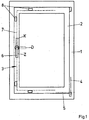
- Figure 1 shows a window with a frame 1 and a sash 2 and with a connecting rod fitting 3 for locking the sash 2 in the frame 1.
- the sash 2 can be pivoted about a vertical axis 4 with respect to the frame 1 into a rotary position and about a horizontal axis 5 tilt with respect to the frame 1 in a tilted position.
- the drive rod fitting 3 can be driven via a handle 6 and has a drive rod 7 for driving several locks 8.
- the handle 6 In the illustrated position, the handle 6 is in position "Z", which indicates the closed position in which the leaf 2 is in the frame 1 and is locked via the locks 8.
- the handle 6 can be moved into a rotary position “D” in which the wing 2 can be rotated about the vertical axis 4.
- a position “K” of the handle 6 the wing 2 can be tilted about the horizontal axis 5 with respect to the frame 1.
- FIG 2 shows a transmission gear of the espagnolette 3 from Figure 1 in the closed position in which the handle 6 is in position "Z".
- the transmission gear 9 has a nut 11 rotatably mounted in a housing 10 for attaching the in Figure 1 handle 6 shown and a portion of the drive rod 7.
- the housing 10 has a housing bottom 26 arranged parallel to the plane of the drawing and a housing cover with a bearing shell (not shown) for mounting the nut 11, which is manufactured in one piece with the drive pinion 13. To simplify the drawing, the housing cover is not shown.
- the transmission gear 9 has a gear 12 with a drive pinion 13 arranged concentrically to the nut 11 for driving a slide 14 and with a toggle lever 17 formed by two levers 15, 16.
- the slide 14 has a series of recesses 18 which the drive pinion 13 meshes with .
- a first lever 15 of the toggle lever 17 is articulated on the slide 14, while the second lever 16 is articulated on the section of the drive rod 7.
- the levers 15, 16 are connected to one another via a bearing pin 19.
- a crank pin 20 is made in one piece with the bearing pin 19 and is guided in a link 21.
- the gate 21 is designed as a recess 27 in at least the housing bottom 26 of the housing 10.
- the housing 10 has a respective guide 22, 23 for the slide 14 and for the section of the drive rod 7.
- the slide 14 is guided on the section of the drive rod 7.
- the drive rod 7 is designed in the shape of a trough to accommodate the slide 14.
- the first lever 15 has a bearing 24 on the slide 14 and the second lever 16 has a bearing 25 on the section of the drive rod 7.
- the gate 21 has a first section 28 inclined to the intended direction of movement of the section of the drive rod 7 and a second section 29 inclined opposite to the first section 28.
- a third section 30 of the gate 21 is arranged parallel to the direction of movement of the section of the drive rod 7 and adjoins the second section 29. In the illustrated closed position, the crank pin 20 is located at the end of the first section 28.
- Figure 5 shows the course of the translation I of the transmission gear 9 when the handle is driven from the “Z” position through the “D” position into the “K” position. Between the “K” position and the “D” position, the transmission gear 9 has a constant ratio. If, starting from position “D”, the transmission gear 9 is moved in the direction of the locking position “Z”, a very high transmission ratio is first achieved, which means that initially with a slight rotation of the nut 11 there is a large displacement of the drive rod 7. Only when the crank pin 20 is in the first section 28 of the link 21 is the portion of the drive rod 7 driven with a low gear ratio. This means that a large rotation of the nut 11 only leads to a small displacement of the section of the drive rod 7.
- Figure 6 shows the course of the longitudinal movement x of the section of the drive rod 7 when the nut 11 is rotated through the positions "K", "D” and "Z".
Landscapes
- Engineering & Computer Science (AREA)
- Mechanical Engineering (AREA)
- Transmission Devices (AREA)
Description
Die Erfindung betrifft ein Übersetzungsgetriebe für einen Treibstangenbeschlag eines Fensters, einer Fenstertür oder dergleichen, mit einer antreibbaren Nuss und einem mit der Nuss gekoppelten Getriebe zum Antrieb einer Treibstange, wobei das Getriebe zwischen einem Schieber und der Treibstange angeordnet ist und ein Übersetzungsverhältnis ungleich 1:1 aufweist, dass die Nuss ein Antriebsritzel hat, dass das Antriebsritzel mit dem Schieber gekoppelt ist und eine Reihe von Ausnehmungen hat, in die das Antriebsritzel eingreift.The invention relates to a transmission gear for a connecting rod fitting of a window, a balcony door or the like, with a drivable nut and a gear coupled to the nut for driving a connecting rod, the gear being arranged between a slide and the connecting rod and a gear ratio not equal to 1: 1 comprises that the nut has a drive pinion, that the drive pinion is coupled to the slide and has a series of recesses into which the drive pinion engages.
Ein Kantengetriebe mit einem Antriebsritzel, welches ein weiteres Ritzel zur Aufnahme der Handhabe aufweist ist aus der
Weiterhin ist aus der
Aus der
Ein solches Übersetzungsgetriebe ist beispielsweise aus der
Aus der
Der Erfindung liegt das Problem zugrunde, ein Antriebsritzel der eingangs genannten Art so weiter zu bilden, dass es einen besonders geringen Bauraum aufweist.The invention is based on the problem of developing a drive pinion of the type mentioned at the beginning in such a way that it has a particularly small installation space.
Dieses Problem wird erfindungsgemäß dadurch gelöst, dass der Schieber auf der Treibstange geführt istThis problem is solved according to the invention in that the slide is guided on the drive rod
Durch diese Gestaltung hat das Übersetzungsgetriebe mit dem Getriebe und mit dem von dem Antriebsritzel angetriebenen Schieber zwei hintereinander angeordnete Einrichtungen, mit jeweils einem eigenen Übersetzungsverhält-Das Übersetzungsgetriebe ermöglicht gemäß einer anderen vorteilhaften Weiterbildung der Erfindung eine besonders leichtgängige Verriegelung des Treibstangenbeschlages, wenn die Kulisse einen geneigt zur vorgesehenen Bewegungsrichtung der Treibstange angeordneten ersten Abschnitt und einen sich daran anschließenden, entgegengesetzt zu dem ersten Abschnitt geneigten zweiten Abschnitt hat. Durch diese Gestaltung hat das Übersetzungsgetriebe eine variable Übersetzung beim Antrieb der Treibstange. Ist der Kurbelzapfen im ersten Abschnitt der Kulisse geführt, erfolgt eine geringe Bewegung der Treibstange bei einer Drehbewegung der Nuss. Wird jedoch der Kurbelzapfen von dem zweiten Abschnitt der Kulisse geführt, hat der Antrieb über die Nuss eine deutlich größere Übersetzung, so dass bei der gleichen Drehbewegung der Nuss die Treibstange wesentlich stärker bewegt wird. Um den Antrieb des Treibstangenbeschlages besonders leichtgängig zu gestalten, lässt sich die Führung des Kurbelzapfens in dem ersten Abschnitt unmittelbar an der Schließstellung anordnen, wenn über die Bewegung der Treibstange mehrere Verschlüsse des Treibstangenbeschlages in die Verriegelungsstellung bewegt werden. In dem zweiten Abschnitt kann der Kurbelzapfen geführt werden, wenn die Verschlüsse voneinander getrennt sind, da in dieser Stellung ein Reibungswiderstand des Treibstangenbeschlages besonders gering ist.Due to this design, the transmission gear with the gear and with the slide driven by the drive pinion has two devices arranged one behind the other, each with its own transmission ratio to the intended direction of movement of the drive rod arranged first section and an adjoining, opposite to the first section inclined second section. As a result of this design, the transmission gear has a variable transmission ratio when driving the drive rod. If the crank pin is guided in the first section of the link, there is a slight movement of the drive rod when the nut rotates. If, however, the crank pin is guided by the second section of the link, the drive via the nut has a significantly greater translation, so that the drive rod is moved much more strongly with the same rotary movement of the nut. In order to make the drive of the drive rod fitting particularly smooth, the guide of the crank pin in the first section can be arranged directly at the closed position if several closures of the drive rod fitting are moved into the locking position via the movement of the drive rod. The crank pin can be guided in the second section when the locks are separated from one another, since in this position the frictional resistance of the drive rod fitting is particularly low.
Ein vorgesehener Weg der Treibstange lässt sich gemäß einer anderen vorteilhaften Weiterbildung der Erfindung einfach einstellen, wenn die Kulisse einen dritten parallel zur Bewegungsrichtung der Treibstange angeordneten Abschnitt hat, welcher sich an den zweiten Abschnitt anschließt. In dem dritten Abschnitt ist der Kurbelzapfen vorzugsweise geführt, wenn der Treibstangenbeschlag von einer Drehstellung in eine Kippstellung angetrieben wird.According to another advantageous development of the invention, an intended path of the drive rod can be easily set if the link has a third section which is arranged parallel to the direction of movement of the drive rod and which adjoins the second section. The crank pin is preferably guided in the third section when the connecting rod fitting is driven from a rotational position to a tilted position.
Das Übersetzungsgetriebe lässt sich gemäß einer anderen vorteilhaften Weiterbildung der Erfindung in besonders flach gestalteten Ausnehmungen des Fensters anordnen, wenn ein Abschnitt der Treibstange wannenförmig zur Aufnahme des Schiebers gestaltet ist.According to another advantageous development of the invention, the transmission gear can be arranged in particularly flat recesses in the window if a section of the drive rod is trough-shaped for receiving the slide.
Die räumliche Zuordnung der Lagerung der Nuss und der Führung des Kurbelzapfens lässt sich gemäß einer anderen vorteilhaften Weiterbildung der Erfindung einfach festlegen, wenn ein Gehäuse einen Gehäuseboden und einen Gehäusedeckel hat, wenn zumindest eines der Bauteile des Gehäusebodens oder des Gehäusedeckels eine Lagerschale für die Nuss und eine Ausnehmung für die Kulisse hat. Durch diese Gestaltung weist das Übersetzungsgetriebe eine besonders hohe Stabilität auf.The spatial assignment of the bearing of the nut and the guide of the crank pin can easily be determined according to another advantageous development of the invention if a housing has a housing base and a housing cover, if at least one of the components of the housing base or the housing cover has a bearing shell for the nut and has a recess for the backdrop. As a result of this design, the transmission gear has a particularly high level of stability.
Zur Vereinfachung des Aufbaus des Übersetzungsgetriebes trägt es gemäß einer anderen vorteilhaften Weiterbildung der Erfindung bei, wenn das Gehäuse jeweils eine Führung für den Schieber und für den Abschnitt der Treibstange hat. Vorzugsweise sind die Führungen von Abwinklungen zumindest eines der Bauteile des Gehäusebodens oder des Gehäusedeckels gebildet. Dies trägt zur weiteren Erhöhung der Stabilität des Übersetzungsgetriebes bei.According to another advantageous development of the invention, it helps to simplify the structure of the transmission gear if the housing has a guide for the slide and for the section of the drive rod. The guides are preferably formed by bends of at least one of the components of the housing base or of the housing cover. This helps to further increase the stability of the transmission gear.
Die Erfindung lässt zahlreiche Ausführungsformen zu. Zur weiteren Verdeutlichung ihres Grundprinzips ist eine davon in der Zeichnung dargestellt und wird nachfolgend beschrieben. Diese zeigt in
- Fig. 1
- ein Fenster mit einem Treibstangenbeschlag,
- Fig. 2
- vergrößert ein Übersetzungsgetriebe des Treibstangenbeschlages in einer Schließstellung,
- Fig. 3
- das Übersetzungsgetriebe aus
Figur 2 - Fig. 4
- das Übersetzungsgetriebe aus
Figur 2 - Fig. 5
- ein Diagramm über den Übersetzungsverlauf des Übersetzungsgetriebes,
- Fig. 6
- ein Diagramm über den Verschiebeweg einer Treibstange beim Antrieb des Übersetzungsgetriebes.
- Fig. 1
- a window with a connecting rod fitting,
- Fig. 2
- enlarges a transmission gear of the espagnolette fitting in a closed position,
- Fig. 3
- the transmission gear off
Figure 2 in a rotary position, - Fig. 4
- the transmission gear off
Figure 2 in a tilted position, - Fig. 5
- a diagram of the transmission ratio of the transmission gear,
- Fig. 6
- a diagram of the displacement path of a drive rod when driving the transmission gear.
Die Kulisse 21 hat einen ersten, geneigt zur vorgesehenen Bewegungsrichtung des Teilstücks der Treibstange 7 angeordneten Abschnitt 28 und einen zweiten, entgegengesetzt zum ersten Abschnitt 28 geneigten Abschnitt 29. Ein dritter Abschnitt 30 der Kulisse 21 ist parallel zur Bewegungsrichtung des Teilstücks der Treibstange 7 angeordnet und schließt sich an den zweiten Abschnitt 29 an. Der Kurbelzapfen 20 befindet sich in der dargestellten Schließstellung am Ende des ersten Abschnitts 28.The
Dreht man die Handhabe 6 ausgehend von der Stellung aus
Dreht man ausgehend von der in
Die niedrige Übersetzung vor der Stellung "Z" führt im montierten Zustand dazu, dass Reibungskräfte der in
Claims (7)
- A transmission gear (9) for a drive rod fitting (3) of a window, a French window or the like, having a drivable nut (11) and a gear (12) coupled with the nut (11) for driving a drive rod (7), wherein the gear (12) is arranged between a slide (4) and the drive rod (7) and has a transmission ratio unequal to 1:1, that the nut (11) has a drive pinion (13), that the drive pinion (13) is coupled with the slide (14) and has a series of recesses (18) into which the drive pinion (13) engages, characterized in that the slide (14) is guided on the drive rod (7),
that the gear (12) has a first lever (15) and a second lever (16) mounted pivotably on the first lever (15), that the levers (15, 16) are arranged to form a toggle lever (17) and that the levers (15, 16) have a crank pin (20) guided in a connecting link (21),and
that the first lever (15) is articulated on the slide (14) and the second lever (16) has a bearing (25) for the articulation to the drive rod (7). - A transmission gear according to any one of Claim 1, characterized in that a bearing pin (19) connecting the two levers (15, 16) with one another is produced in one piece with the crank pin (20).
- A transmission gear according to any one of Claims 1 to 2, characterized in that the connecting link (21) has a first section (28) arranged inclined towards the intended direction of movement of the drive rod (7) and an adjoining second section (29) inclined opposite to the first section (28).
- A transmission gear according to Claim 3, characterized in that the connecting link (21) has a third section (30) arranged parallel to the direction of movement of the drive rod (7), which third section adjoins the second section (29).
- A transmission gear according to any one of Claims 1 to 4, characterized in that a section of the drive rod (7) is designed trough-shaped for accommodating the slide (14).
- A transmission gear according to any one of Claims 1 to 5, characterized in that a housing (10) has a housing base (26) and a housing cover, and that at least one of the components of the housing base (26) or of the housing cover has a bearing shell for the nut (11) and a recess (27) for the connecting link (21).
- A transmission gear according to Claim 6, characterized in that the housing (10) in each case has a guide (22, 23) for the slide (14) and for the section of the drive rod (7).
Applications Claiming Priority (1)
| Application Number | Priority Date | Filing Date | Title |
|---|---|---|---|
| DE102016202064.1A DE102016202064A1 (en) | 2016-02-11 | 2016-02-11 | Transmission gear for a drive rod fitting |
Publications (3)
| Publication Number | Publication Date |
|---|---|
| EP3205797A1 EP3205797A1 (en) | 2017-08-16 |
| EP3205797B1 EP3205797B1 (en) | 2018-10-24 |
| EP3205797B2 true EP3205797B2 (en) | 2021-09-01 |
Family
ID=57794146
Family Applications (1)
| Application Number | Title | Priority Date | Filing Date |
|---|---|---|---|
| EP17150925.0A Active EP3205797B2 (en) | 2016-02-11 | 2017-01-11 | Transmission gearing for an espagnolette fitting |
Country Status (2)
| Country | Link |
|---|---|
| EP (1) | EP3205797B2 (en) |
| DE (2) | DE102016202064A1 (en) |
Citations (2)
| Publication number | Priority date | Publication date | Assignee | Title |
|---|---|---|---|---|
| DE1196538B (en) † | 1958-07-29 | 1965-07-08 | Ver Baubeschlag Gretsch Co | Control gear for two successive sliding movements of two output members connected in parallel to a drive member, in particular for unlocking and opening the sash of windows, doors or the like. |
| JPH0882140A (en) † | 1994-09-12 | 1996-03-26 | Takigen Mfg Co Ltd | Handle device for locking |
Family Cites Families (6)
| Publication number | Priority date | Publication date | Assignee | Title |
|---|---|---|---|---|
| DE1244611B (en) * | 1963-08-26 | 1967-07-13 | Jaeger Frank K G | Actuation gear for longitudinally displaceable connecting rods on windows, doors, flaps or the like, especially for tilt and swivel wings |
| DE9112079U1 (en) | 1991-09-27 | 1993-01-28 | Siegenia-Frank Kg, 5900 Siegen | Actuating gear for longitudinally adjustable drive rods on fittings of windows and doors etc. |
| CN1163977A (en) * | 1996-03-28 | 1997-11-05 | 泷源制造株式会社 | Locking handle assembly |
| WO2004083575A1 (en) * | 2003-03-19 | 2004-09-30 | Mul-T-Lock Technologies Ltd. | Enhanced extendable multipoint lock |
| DE10354185B4 (en) * | 2003-11-20 | 2015-04-02 | Aug. Winkhaus Gmbh & Co. Kg | espagnolette |
| PL2366855T3 (en) | 2010-03-19 | 2014-12-31 | Roto Frank Ag | Fitting for a window, door or similar and window, door or similar with a fitting |
-
2016
- 2016-02-11 DE DE102016202064.1A patent/DE102016202064A1/en not_active Withdrawn
-
2017
- 2017-01-11 DE DE202017007199.1U patent/DE202017007199U1/en active Active
- 2017-01-11 EP EP17150925.0A patent/EP3205797B2/en active Active
Patent Citations (2)
| Publication number | Priority date | Publication date | Assignee | Title |
|---|---|---|---|---|
| DE1196538B (en) † | 1958-07-29 | 1965-07-08 | Ver Baubeschlag Gretsch Co | Control gear for two successive sliding movements of two output members connected in parallel to a drive member, in particular for unlocking and opening the sash of windows, doors or the like. |
| JPH0882140A (en) † | 1994-09-12 | 1996-03-26 | Takigen Mfg Co Ltd | Handle device for locking |
Also Published As
| Publication number | Publication date |
|---|---|
| DE102016202064A1 (en) | 2017-08-17 |
| EP3205797B1 (en) | 2018-10-24 |
| EP3205797A1 (en) | 2017-08-16 |
| DE202017007199U1 (en) | 2020-01-20 |
Similar Documents
| Publication | Publication Date | Title |
|---|---|---|
| DE202017106376U1 (en) | Caravan window and opening mechanism for it | |
| DE202007015503U1 (en) | A drive | |
| DE3723453C2 (en) | ||
| DE102015206577A1 (en) | Domestic appliance with a retractable in a storage space door with an elliptical backdrop for moving a bearing bracket of a door storage unit | |
| EP2143859B1 (en) | Locking device | |
| EP3205797B2 (en) | Transmission gearing for an espagnolette fitting | |
| EP2366855B1 (en) | Fitting for a window, door or similar and window, door or similar with a fitting | |
| EP2733286A2 (en) | Pivoting lever closure with low installation depth | |
| EP3656960A2 (en) | Vehicle hatch kinematics | |
| EP3205798B2 (en) | Drive gear for an espagnolette fitting | |
| EP4004314B1 (en) | Drive unit for motor-vehicle applications | |
| EP3128109B1 (en) | Drive transmission for a fitting on a connecting rod | |
| DE10354185A1 (en) | espagnolette | |
| EP1288418B1 (en) | Fitting for a tilting or tilting-and-turning window | |
| DE10301584B4 (en) | Device for the displaceable arrangement of a panel | |
| DE1942566A1 (en) | Device for corner deflection for in the wing or in the fixed frame of a window or the like. guided control rods | |
| EP3299559B1 (en) | Locking assembly for a window | |
| DE1266173B (en) | Gear of an espagnolette fitting for windows, doors or the like, especially for tilt and swivel sash windows | |
| AT406176B (en) | MULTI-LOCK CLOSURE | |
| EP1533454B1 (en) | Espagnolette fitting | |
| WO2024033062A1 (en) | Opening device | |
| WO2019219116A1 (en) | Electric motor drive for motor vehicle applications | |
| WO2023046436A1 (en) | Adjustment device for adusting a vehicle door, and vehicle door | |
| EP2735678B1 (en) | Fitting for windows, doors or similar | |
| EP1619332B1 (en) | Drive gear for an espagnolette fitting |
Legal Events
| Date | Code | Title | Description |
|---|---|---|---|
| REG | Reference to a national code |
Ref country code: DE Ref legal event code: R138 Ref document number: 202017007199 Country of ref document: DE Free format text: GERMAN DOCUMENT NUMBER IS 502017000271 |
|
| PUAI | Public reference made under article 153(3) epc to a published international application that has entered the european phase |
Free format text: ORIGINAL CODE: 0009012 |
|
| STAA | Information on the status of an ep patent application or granted ep patent |
Free format text: STATUS: THE APPLICATION HAS BEEN PUBLISHED |
|
| AK | Designated contracting states |
Kind code of ref document: A1 Designated state(s): AL AT BE BG CH CY CZ DE DK EE ES FI FR GB GR HR HU IE IS IT LI LT LU LV MC MK MT NL NO PL PT RO RS SE SI SK SM TR |
|
| AX | Request for extension of the european patent |
Extension state: BA ME |
|
| STAA | Information on the status of an ep patent application or granted ep patent |
Free format text: STATUS: REQUEST FOR EXAMINATION WAS MADE |
|
| 17P | Request for examination filed |
Effective date: 20180130 |
|
| RBV | Designated contracting states (corrected) |
Designated state(s): AL AT BE BG CH CY CZ DE DK EE ES FI FR GB GR HR HU IE IS IT LI LT LU LV MC MK MT NL NO PL PT RO RS SE SI SK SM TR |
|
| GRAP | Despatch of communication of intention to grant a patent |
Free format text: ORIGINAL CODE: EPIDOSNIGR1 |
|
| STAA | Information on the status of an ep patent application or granted ep patent |
Free format text: STATUS: GRANT OF PATENT IS INTENDED |
|
| INTG | Intention to grant announced |
Effective date: 20180531 |
|
| GRAS | Grant fee paid |
Free format text: ORIGINAL CODE: EPIDOSNIGR3 |
|
| GRAA | (expected) grant |
Free format text: ORIGINAL CODE: 0009210 |
|
| STAA | Information on the status of an ep patent application or granted ep patent |
Free format text: STATUS: THE PATENT HAS BEEN GRANTED |
|
| AK | Designated contracting states |
Kind code of ref document: B1 Designated state(s): AL AT BE BG CH CY CZ DE DK EE ES FI FR GB GR HR HU IE IS IT LI LT LU LV MC MK MT NL NO PL PT RO RS SE SI SK SM TR |
|
| REG | Reference to a national code |
Ref country code: CH Ref legal event code: EP |
|
| REG | Reference to a national code |
Ref country code: IE Ref legal event code: FG4D Free format text: LANGUAGE OF EP DOCUMENT: GERMAN |
|
| REG | Reference to a national code |
Ref country code: AT Ref legal event code: REF Ref document number: 1056858 Country of ref document: AT Kind code of ref document: T Effective date: 20181115 |
|
| REG | Reference to a national code |
Ref country code: DE Ref legal event code: R096 Ref document number: 502017000271 Country of ref document: DE |
|
| REG | Reference to a national code |
Ref country code: NL Ref legal event code: MP Effective date: 20181024 |
|
| REG | Reference to a national code |
Ref country code: LT Ref legal event code: MG4D |
|
| PG25 | Lapsed in a contracting state [announced via postgrant information from national office to epo] |
Ref country code: NL Free format text: LAPSE BECAUSE OF FAILURE TO SUBMIT A TRANSLATION OF THE DESCRIPTION OR TO PAY THE FEE WITHIN THE PRESCRIBED TIME-LIMIT Effective date: 20181024 |
|
| PG25 | Lapsed in a contracting state [announced via postgrant information from national office to epo] |
Ref country code: LT Free format text: LAPSE BECAUSE OF FAILURE TO SUBMIT A TRANSLATION OF THE DESCRIPTION OR TO PAY THE FEE WITHIN THE PRESCRIBED TIME-LIMIT Effective date: 20181024 Ref country code: ES Free format text: LAPSE BECAUSE OF FAILURE TO SUBMIT A TRANSLATION OF THE DESCRIPTION OR TO PAY THE FEE WITHIN THE PRESCRIBED TIME-LIMIT Effective date: 20181024 Ref country code: IS Free format text: LAPSE BECAUSE OF FAILURE TO SUBMIT A TRANSLATION OF THE DESCRIPTION OR TO PAY THE FEE WITHIN THE PRESCRIBED TIME-LIMIT Effective date: 20190224 Ref country code: HR Free format text: LAPSE BECAUSE OF FAILURE TO SUBMIT A TRANSLATION OF THE DESCRIPTION OR TO PAY THE FEE WITHIN THE PRESCRIBED TIME-LIMIT Effective date: 20181024 Ref country code: BG Free format text: LAPSE BECAUSE OF FAILURE TO SUBMIT A TRANSLATION OF THE DESCRIPTION OR TO PAY THE FEE WITHIN THE PRESCRIBED TIME-LIMIT Effective date: 20190124 Ref country code: PL Free format text: LAPSE BECAUSE OF FAILURE TO SUBMIT A TRANSLATION OF THE DESCRIPTION OR TO PAY THE FEE WITHIN THE PRESCRIBED TIME-LIMIT Effective date: 20181024 Ref country code: NO Free format text: LAPSE BECAUSE OF FAILURE TO SUBMIT A TRANSLATION OF THE DESCRIPTION OR TO PAY THE FEE WITHIN THE PRESCRIBED TIME-LIMIT Effective date: 20190124 Ref country code: FI Free format text: LAPSE BECAUSE OF FAILURE TO SUBMIT A TRANSLATION OF THE DESCRIPTION OR TO PAY THE FEE WITHIN THE PRESCRIBED TIME-LIMIT Effective date: 20181024 Ref country code: LV Free format text: LAPSE BECAUSE OF FAILURE TO SUBMIT A TRANSLATION OF THE DESCRIPTION OR TO PAY THE FEE WITHIN THE PRESCRIBED TIME-LIMIT Effective date: 20181024 |
|
| PG25 | Lapsed in a contracting state [announced via postgrant information from national office to epo] |
Ref country code: RS Free format text: LAPSE BECAUSE OF FAILURE TO SUBMIT A TRANSLATION OF THE DESCRIPTION OR TO PAY THE FEE WITHIN THE PRESCRIBED TIME-LIMIT Effective date: 20181024 Ref country code: AL Free format text: LAPSE BECAUSE OF FAILURE TO SUBMIT A TRANSLATION OF THE DESCRIPTION OR TO PAY THE FEE WITHIN THE PRESCRIBED TIME-LIMIT Effective date: 20181024 Ref country code: GR Free format text: LAPSE BECAUSE OF FAILURE TO SUBMIT A TRANSLATION OF THE DESCRIPTION OR TO PAY THE FEE WITHIN THE PRESCRIBED TIME-LIMIT Effective date: 20190125 Ref country code: PT Free format text: LAPSE BECAUSE OF FAILURE TO SUBMIT A TRANSLATION OF THE DESCRIPTION OR TO PAY THE FEE WITHIN THE PRESCRIBED TIME-LIMIT Effective date: 20190224 Ref country code: SE Free format text: LAPSE BECAUSE OF FAILURE TO SUBMIT A TRANSLATION OF THE DESCRIPTION OR TO PAY THE FEE WITHIN THE PRESCRIBED TIME-LIMIT Effective date: 20181024 |
|
| REG | Reference to a national code |
Ref country code: DE Ref legal event code: R026 Ref document number: 502017000271 Country of ref document: DE |
|
| PG25 | Lapsed in a contracting state [announced via postgrant information from national office to epo] |
Ref country code: DK Free format text: LAPSE BECAUSE OF FAILURE TO SUBMIT A TRANSLATION OF THE DESCRIPTION OR TO PAY THE FEE WITHIN THE PRESCRIBED TIME-LIMIT Effective date: 20181024 Ref country code: IT Free format text: LAPSE BECAUSE OF FAILURE TO SUBMIT A TRANSLATION OF THE DESCRIPTION OR TO PAY THE FEE WITHIN THE PRESCRIBED TIME-LIMIT Effective date: 20181024 Ref country code: CZ Free format text: LAPSE BECAUSE OF FAILURE TO SUBMIT A TRANSLATION OF THE DESCRIPTION OR TO PAY THE FEE WITHIN THE PRESCRIBED TIME-LIMIT Effective date: 20181024 |
|
| PLBI | Opposition filed |
Free format text: ORIGINAL CODE: 0009260 |
|
| PLAX | Notice of opposition and request to file observation + time limit sent |
Free format text: ORIGINAL CODE: EPIDOSNOBS2 |
|
| PG25 | Lapsed in a contracting state [announced via postgrant information from national office to epo] |
Ref country code: RO Free format text: LAPSE BECAUSE OF FAILURE TO SUBMIT A TRANSLATION OF THE DESCRIPTION OR TO PAY THE FEE WITHIN THE PRESCRIBED TIME-LIMIT Effective date: 20181024 Ref country code: MC Free format text: LAPSE BECAUSE OF FAILURE TO SUBMIT A TRANSLATION OF THE DESCRIPTION OR TO PAY THE FEE WITHIN THE PRESCRIBED TIME-LIMIT Effective date: 20181024 Ref country code: SK Free format text: LAPSE BECAUSE OF FAILURE TO SUBMIT A TRANSLATION OF THE DESCRIPTION OR TO PAY THE FEE WITHIN THE PRESCRIBED TIME-LIMIT Effective date: 20181024 Ref country code: EE Free format text: LAPSE BECAUSE OF FAILURE TO SUBMIT A TRANSLATION OF THE DESCRIPTION OR TO PAY THE FEE WITHIN THE PRESCRIBED TIME-LIMIT Effective date: 20181024 Ref country code: SM Free format text: LAPSE BECAUSE OF FAILURE TO SUBMIT A TRANSLATION OF THE DESCRIPTION OR TO PAY THE FEE WITHIN THE PRESCRIBED TIME-LIMIT Effective date: 20181024 |
|
| 26 | Opposition filed |
Opponent name: GEZE GMBH Effective date: 20190723 |
|
| PG25 | Lapsed in a contracting state [announced via postgrant information from national office to epo] |
Ref country code: LU Free format text: LAPSE BECAUSE OF NON-PAYMENT OF DUE FEES Effective date: 20190111 |
|
| REG | Reference to a national code |
Ref country code: BE Ref legal event code: MM Effective date: 20190131 |
|
| REG | Reference to a national code |
Ref country code: IE Ref legal event code: MM4A |
|
| PG25 | Lapsed in a contracting state [announced via postgrant information from national office to epo] |
Ref country code: SI Free format text: LAPSE BECAUSE OF FAILURE TO SUBMIT A TRANSLATION OF THE DESCRIPTION OR TO PAY THE FEE WITHIN THE PRESCRIBED TIME-LIMIT Effective date: 20181024 |
|
| PG25 | Lapsed in a contracting state [announced via postgrant information from national office to epo] |
Ref country code: BE Free format text: LAPSE BECAUSE OF NON-PAYMENT OF DUE FEES Effective date: 20190131 |
|
| PLBB | Reply of patent proprietor to notice(s) of opposition received |
Free format text: ORIGINAL CODE: EPIDOSNOBS3 |
|
| PG25 | Lapsed in a contracting state [announced via postgrant information from national office to epo] |
Ref country code: IE Free format text: LAPSE BECAUSE OF NON-PAYMENT OF DUE FEES Effective date: 20190111 |
|
| PG25 | Lapsed in a contracting state [announced via postgrant information from national office to epo] |
Ref country code: TR Free format text: LAPSE BECAUSE OF FAILURE TO SUBMIT A TRANSLATION OF THE DESCRIPTION OR TO PAY THE FEE WITHIN THE PRESCRIBED TIME-LIMIT Effective date: 20181024 |
|
| PG25 | Lapsed in a contracting state [announced via postgrant information from national office to epo] |
Ref country code: MT Free format text: LAPSE BECAUSE OF FAILURE TO SUBMIT A TRANSLATION OF THE DESCRIPTION OR TO PAY THE FEE WITHIN THE PRESCRIBED TIME-LIMIT Effective date: 20181024 |
|
| REG | Reference to a national code |
Ref country code: CH Ref legal event code: PL |
|
| PG25 | Lapsed in a contracting state [announced via postgrant information from national office to epo] |
Ref country code: LI Free format text: LAPSE BECAUSE OF NON-PAYMENT OF DUE FEES Effective date: 20200131 Ref country code: CH Free format text: LAPSE BECAUSE OF NON-PAYMENT OF DUE FEES Effective date: 20200131 |
|
| PG25 | Lapsed in a contracting state [announced via postgrant information from national office to epo] |
Ref country code: CY Free format text: LAPSE BECAUSE OF FAILURE TO SUBMIT A TRANSLATION OF THE DESCRIPTION OR TO PAY THE FEE WITHIN THE PRESCRIBED TIME-LIMIT Effective date: 20181024 |
|
| PG25 | Lapsed in a contracting state [announced via postgrant information from national office to epo] |
Ref country code: HU Free format text: LAPSE BECAUSE OF FAILURE TO SUBMIT A TRANSLATION OF THE DESCRIPTION OR TO PAY THE FEE WITHIN THE PRESCRIBED TIME-LIMIT; INVALID AB INITIO Effective date: 20170111 |
|
| PUAH | Patent maintained in amended form |
Free format text: ORIGINAL CODE: 0009272 |
|
| STAA | Information on the status of an ep patent application or granted ep patent |
Free format text: STATUS: PATENT MAINTAINED AS AMENDED |
|
| 27A | Patent maintained in amended form |
Effective date: 20210901 |
|
| AK | Designated contracting states |
Kind code of ref document: B2 Designated state(s): AL AT BE BG CH CY CZ DE DK EE ES FI FR GB GR HR HU IE IS IT LI LT LU LV MC MK MT NL NO PL PT RO RS SE SI SK SM TR |
|
| REG | Reference to a national code |
Ref country code: DE Ref legal event code: R102 Ref document number: 502017000271 Country of ref document: DE |
|
| GBPC | Gb: european patent ceased through non-payment of renewal fee |
Effective date: 20210111 |
|
| PG25 | Lapsed in a contracting state [announced via postgrant information from national office to epo] |
Ref country code: GB Free format text: LAPSE BECAUSE OF NON-PAYMENT OF DUE FEES Effective date: 20210111 |
|
| PG25 | Lapsed in a contracting state [announced via postgrant information from national office to epo] |
Ref country code: MK Free format text: LAPSE BECAUSE OF FAILURE TO SUBMIT A TRANSLATION OF THE DESCRIPTION OR TO PAY THE FEE WITHIN THE PRESCRIBED TIME-LIMIT Effective date: 20181024 |
|
| P01 | Opt-out of the competence of the unified patent court (upc) registered |
Effective date: 20230516 |
|
| PGFP | Annual fee paid to national office [announced via postgrant information from national office to epo] |
Ref country code: AT Payment date: 20240118 Year of fee payment: 8 |
|
| PGFP | Annual fee paid to national office [announced via postgrant information from national office to epo] |
Ref country code: DE Payment date: 20240119 Year of fee payment: 8 |
|
| PGFP | Annual fee paid to national office [announced via postgrant information from national office to epo] |
Ref country code: FR Payment date: 20240123 Year of fee payment: 8 |