EP3656960A2 - Vehicle hatch kinematics - Google Patents
Vehicle hatch kinematics Download PDFInfo
- Publication number
- EP3656960A2 EP3656960A2 EP19210141.8A EP19210141A EP3656960A2 EP 3656960 A2 EP3656960 A2 EP 3656960A2 EP 19210141 A EP19210141 A EP 19210141A EP 3656960 A2 EP3656960 A2 EP 3656960A2
- Authority
- EP
- European Patent Office
- Prior art keywords
- actuator
- gear
- relative
- spindle
- length
- Prior art date
- Legal status (The legal status is an assumption and is not a legal conclusion. Google has not performed a legal analysis and makes no representation as to the accuracy of the status listed.)
- Pending
Links
- 238000006073 displacement reaction Methods 0.000 claims abstract description 25
- 230000008878 coupling Effects 0.000 claims description 37
- 238000010168 coupling process Methods 0.000 claims description 37
- 238000005859 coupling reaction Methods 0.000 claims description 37
- 230000004913 activation Effects 0.000 claims description 17
- 230000008859 change Effects 0.000 claims description 11
- 125000006850 spacer group Chemical group 0.000 claims description 9
- 230000005540 biological transmission Effects 0.000 claims description 5
- 239000011295 pitch Substances 0.000 description 18
- 238000009434 installation Methods 0.000 description 4
- 238000005253 cladding Methods 0.000 description 3
- 230000000712 assembly Effects 0.000 description 1
- 238000000429 assembly Methods 0.000 description 1
- 230000007246 mechanism Effects 0.000 description 1
- ORQBXQOJMQIAOY-UHFFFAOYSA-N nobelium Chemical compound [No] ORQBXQOJMQIAOY-UHFFFAOYSA-N 0.000 description 1
- 238000004904 shortening Methods 0.000 description 1
- 230000001360 synchronised effect Effects 0.000 description 1
Images


Classifications
-
- E—FIXED CONSTRUCTIONS
- E05—LOCKS; KEYS; WINDOW OR DOOR FITTINGS; SAFES
- E05F—DEVICES FOR MOVING WINGS INTO OPEN OR CLOSED POSITION; CHECKS FOR WINGS; WING FITTINGS NOT OTHERWISE PROVIDED FOR, CONCERNED WITH THE FUNCTIONING OF THE WING
- E05F15/00—Power-operated mechanisms for wings
- E05F15/60—Power-operated mechanisms for wings using electrical actuators
- E05F15/603—Power-operated mechanisms for wings using electrical actuators using rotary electromotors
- E05F15/611—Power-operated mechanisms for wings using electrical actuators using rotary electromotors for swinging wings
- E05F15/616—Power-operated mechanisms for wings using electrical actuators using rotary electromotors for swinging wings operated by push-pull mechanisms
- E05F15/622—Power-operated mechanisms for wings using electrical actuators using rotary electromotors for swinging wings operated by push-pull mechanisms using screw-and-nut mechanisms
-
- B—PERFORMING OPERATIONS; TRANSPORTING
- B60—VEHICLES IN GENERAL
- B60J—WINDOWS, WINDSCREENS, NON-FIXED ROOFS, DOORS, OR SIMILAR DEVICES FOR VEHICLES; REMOVABLE EXTERNAL PROTECTIVE COVERINGS SPECIALLY ADAPTED FOR VEHICLES
- B60J5/00—Doors
- B60J5/04—Doors arranged at the vehicle sides
- B60J5/047—Doors arranged at the vehicle sides characterised by the opening or closing movement
-
- B—PERFORMING OPERATIONS; TRANSPORTING
- B60—VEHICLES IN GENERAL
- B60J—WINDOWS, WINDSCREENS, NON-FIXED ROOFS, DOORS, OR SIMILAR DEVICES FOR VEHICLES; REMOVABLE EXTERNAL PROTECTIVE COVERINGS SPECIALLY ADAPTED FOR VEHICLES
- B60J5/00—Doors
- B60J5/04—Doors arranged at the vehicle sides
- B60J5/06—Doors arranged at the vehicle sides slidable; foldable
- B60J5/062—Doors arranged at the vehicle sides slidable; foldable for utility vehicles or public transport
-
- E—FIXED CONSTRUCTIONS
- E05—LOCKS; KEYS; WINDOW OR DOOR FITTINGS; SAFES
- E05F—DEVICES FOR MOVING WINGS INTO OPEN OR CLOSED POSITION; CHECKS FOR WINGS; WING FITTINGS NOT OTHERWISE PROVIDED FOR, CONCERNED WITH THE FUNCTIONING OF THE WING
- E05F15/00—Power-operated mechanisms for wings
- E05F15/60—Power-operated mechanisms for wings using electrical actuators
- E05F15/603—Power-operated mechanisms for wings using electrical actuators using rotary electromotors
- E05F15/611—Power-operated mechanisms for wings using electrical actuators using rotary electromotors for swinging wings
- E05F15/63—Power-operated mechanisms for wings using electrical actuators using rotary electromotors for swinging wings operated by swinging arms
-
- F—MECHANICAL ENGINEERING; LIGHTING; HEATING; WEAPONS; BLASTING
- F16—ENGINEERING ELEMENTS AND UNITS; GENERAL MEASURES FOR PRODUCING AND MAINTAINING EFFECTIVE FUNCTIONING OF MACHINES OR INSTALLATIONS; THERMAL INSULATION IN GENERAL
- F16H—GEARING
- F16H1/00—Toothed gearings for conveying rotary motion
- F16H1/02—Toothed gearings for conveying rotary motion without gears having orbital motion
- F16H1/04—Toothed gearings for conveying rotary motion without gears having orbital motion involving only two intermeshing members
- F16H1/12—Toothed gearings for conveying rotary motion without gears having orbital motion involving only two intermeshing members with non-parallel axes
- F16H1/14—Toothed gearings for conveying rotary motion without gears having orbital motion involving only two intermeshing members with non-parallel axes comprising conical gears only
-
- F—MECHANICAL ENGINEERING; LIGHTING; HEATING; WEAPONS; BLASTING
- F16—ENGINEERING ELEMENTS AND UNITS; GENERAL MEASURES FOR PRODUCING AND MAINTAINING EFFECTIVE FUNCTIONING OF MACHINES OR INSTALLATIONS; THERMAL INSULATION IN GENERAL
- F16H—GEARING
- F16H25/00—Gearings comprising primarily only cams, cam-followers and screw-and-nut mechanisms
- F16H25/18—Gearings comprising primarily only cams, cam-followers and screw-and-nut mechanisms for conveying or interconverting oscillating or reciprocating motions
- F16H25/20—Screw mechanisms
-
- F—MECHANICAL ENGINEERING; LIGHTING; HEATING; WEAPONS; BLASTING
- F16—ENGINEERING ELEMENTS AND UNITS; GENERAL MEASURES FOR PRODUCING AND MAINTAINING EFFECTIVE FUNCTIONING OF MACHINES OR INSTALLATIONS; THERMAL INSULATION IN GENERAL
- F16H—GEARING
- F16H37/00—Combinations of mechanical gearings, not provided for in groups F16H1/00 - F16H35/00
- F16H37/12—Gearings comprising primarily toothed or friction gearing, links or levers, and cams, or members of at least two of these types
- F16H37/124—Gearings comprising primarily toothed or friction gearing, links or levers, and cams, or members of at least two of these types for interconverting rotary motion and reciprocating motion
-
- E—FIXED CONSTRUCTIONS
- E05—LOCKS; KEYS; WINDOW OR DOOR FITTINGS; SAFES
- E05D—HINGES OR SUSPENSION DEVICES FOR DOORS, WINDOWS OR WINGS
- E05D15/00—Suspension arrangements for wings
- E05D15/06—Suspension arrangements for wings for wings sliding horizontally more or less in their own plane
- E05D15/10—Suspension arrangements for wings for wings sliding horizontally more or less in their own plane movable out of one plane into a second parallel plane
- E05D15/1005—Suspension arrangements for wings for wings sliding horizontally more or less in their own plane movable out of one plane into a second parallel plane the wing being supported on arms movable in horizontal planes
- E05D15/1007—Suspension arrangements for wings for wings sliding horizontally more or less in their own plane movable out of one plane into a second parallel plane the wing being supported on arms movable in horizontal planes specially adapted for use in railway-cars or mass transit vehicles
-
- E—FIXED CONSTRUCTIONS
- E05—LOCKS; KEYS; WINDOW OR DOOR FITTINGS; SAFES
- E05D—HINGES OR SUSPENSION DEVICES FOR DOORS, WINDOWS OR WINGS
- E05D15/00—Suspension arrangements for wings
- E05D15/28—Suspension arrangements for wings supported on arms movable in horizontal plane
-
- E—FIXED CONSTRUCTIONS
- E05—LOCKS; KEYS; WINDOW OR DOOR FITTINGS; SAFES
- E05Y—INDEXING SCHEME RELATING TO HINGES OR OTHER SUSPENSION DEVICES FOR DOORS, WINDOWS OR WINGS AND DEVICES FOR MOVING WINGS INTO OPEN OR CLOSED POSITION, CHECKS FOR WINGS AND WING FITTINGS NOT OTHERWISE PROVIDED FOR, CONCERNED WITH THE FUNCTIONING OF THE WING
- E05Y2201/00—Constructional elements; Accessories therefore
- E05Y2201/60—Suspension or transmission members; Accessories therefore
- E05Y2201/622—Suspension or transmission members elements
- E05Y2201/686—Rods, links
-
- E—FIXED CONSTRUCTIONS
- E05—LOCKS; KEYS; WINDOW OR DOOR FITTINGS; SAFES
- E05Y—INDEXING SCHEME RELATING TO HINGES OR OTHER SUSPENSION DEVICES FOR DOORS, WINDOWS OR WINGS AND DEVICES FOR MOVING WINGS INTO OPEN OR CLOSED POSITION, CHECKS FOR WINGS AND WING FITTINGS NOT OTHERWISE PROVIDED FOR, CONCERNED WITH THE FUNCTIONING OF THE WING
- E05Y2201/00—Constructional elements; Accessories therefore
- E05Y2201/60—Suspension or transmission members; Accessories therefore
- E05Y2201/622—Suspension or transmission members elements
- E05Y2201/696—Screw mechanisms
-
- E—FIXED CONSTRUCTIONS
- E05—LOCKS; KEYS; WINDOW OR DOOR FITTINGS; SAFES
- E05Y—INDEXING SCHEME RELATING TO HINGES OR OTHER SUSPENSION DEVICES FOR DOORS, WINDOWS OR WINGS AND DEVICES FOR MOVING WINGS INTO OPEN OR CLOSED POSITION, CHECKS FOR WINGS AND WING FITTINGS NOT OTHERWISE PROVIDED FOR, CONCERNED WITH THE FUNCTIONING OF THE WING
- E05Y2201/00—Constructional elements; Accessories therefore
- E05Y2201/60—Suspension or transmission members; Accessories therefore
- E05Y2201/622—Suspension or transmission members elements
- E05Y2201/71—Toothed gearing
- E05Y2201/716—Pinions
- E05Y2201/718—Bevelled pinions
-
- E—FIXED CONSTRUCTIONS
- E05—LOCKS; KEYS; WINDOW OR DOOR FITTINGS; SAFES
- E05Y—INDEXING SCHEME RELATING TO HINGES OR OTHER SUSPENSION DEVICES FOR DOORS, WINDOWS OR WINGS AND DEVICES FOR MOVING WINGS INTO OPEN OR CLOSED POSITION, CHECKS FOR WINGS AND WING FITTINGS NOT OTHERWISE PROVIDED FOR, CONCERNED WITH THE FUNCTIONING OF THE WING
- E05Y2900/00—Application of doors, windows, wings or fittings thereof
- E05Y2900/50—Application of doors, windows, wings or fittings thereof for vehicles
- E05Y2900/506—Application of doors, windows, wings or fittings thereof for vehicles for buses
-
- E—FIXED CONSTRUCTIONS
- E05—LOCKS; KEYS; WINDOW OR DOOR FITTINGS; SAFES
- E05Y—INDEXING SCHEME RELATING TO HINGES OR OTHER SUSPENSION DEVICES FOR DOORS, WINDOWS OR WINGS AND DEVICES FOR MOVING WINGS INTO OPEN OR CLOSED POSITION, CHECKS FOR WINGS AND WING FITTINGS NOT OTHERWISE PROVIDED FOR, CONCERNED WITH THE FUNCTIONING OF THE WING
- E05Y2900/00—Application of doors, windows, wings or fittings thereof
- E05Y2900/50—Application of doors, windows, wings or fittings thereof for vehicles
- E05Y2900/53—Application of doors, windows, wings or fittings thereof for vehicles characterised by the type of wing
- E05Y2900/531—Doors
-
- F—MECHANICAL ENGINEERING; LIGHTING; HEATING; WEAPONS; BLASTING
- F16—ENGINEERING ELEMENTS AND UNITS; GENERAL MEASURES FOR PRODUCING AND MAINTAINING EFFECTIVE FUNCTIONING OF MACHINES OR INSTALLATIONS; THERMAL INSULATION IN GENERAL
- F16H—GEARING
- F16H25/00—Gearings comprising primarily only cams, cam-followers and screw-and-nut mechanisms
- F16H25/18—Gearings comprising primarily only cams, cam-followers and screw-and-nut mechanisms for conveying or interconverting oscillating or reciprocating motions
- F16H25/20—Screw mechanisms
- F16H2025/2062—Arrangements for driving the actuator
- F16H2025/2084—Perpendicular arrangement of drive motor to screw axis
Definitions
- the present invention relates to an actuator which is set up to displace two superordinate assemblies, between which the actuator is arranged, relative to one another.
- Actuators of this type are known, for example, in the area of vehicle doors, such as swing doors on buses. Therefore, the invention will be described below with reference to this application, it being expressly pointed out that the invention is of course not to be limited to this.
- rigid coupling rods which are connected on the one hand to a body of the vehicle and on the other hand to the door. If the door is now displaced relative to the body, the door follows a path predetermined by the coupling rods. Since the path of the possible displacement of the door relative to the body is mostly circular, the attachment point of the coupling rods on the body is predetermined. Furthermore, the rigid coupling rod usually first swings the door far away from the body until it lies against the body in its open state.
- an actuator comprising a spindle drive which has a spindle and one with the spindle in Includes threaded spindle nut, a first gear wheel which is rotationally coupled to the spindle or the spindle nut, the other of the spindle nut or the spindle being connected to a first connecting unit for connecting the actuator to a first higher-level assembly, wherein the spindle drive is set up such that a rotation of the first gear wheel causes a translational displacement of the first connection unit, and a second gearwheel which engages with the first gearwheel and which is rotationally coupled to a second connecting unit for connecting the actuator to a second superordinate assembly, a longitudinal axis of the spindle drive being inclined to a central axis, in particular to an axis of rotation, of the second gearwheel , wherein the actuator is set up so that a relative rotation of the two gears to one another causes actuation of the spindle drive and a displacement of the spindle drive relative to the central axis
- Such an actuator enables two combined movements. On the one hand a rotation of the spindle drive, and thus the first higher-level assembly connected to the spindle drive, relative to the second higher-level assembly, and on the other hand a translational displacement of the first higher-level assembly relative to the axis of rotation of the spindle drive relative to the second higher-level assembly.
- a “rotation of the spindle drive” can be understood to mean that the entire spindle drive or at least the spindle and the spindle nut are displaced together.
- a “rotation of the spindle drive” mean that a central axis of the spindle and / or the spindle nut is rotated about an element connected to the second superordinate assembly, for example a central axis of the second connecting unit or a central axis of the second gear wheel.
- a" Inclination "of the longitudinal axis of the spindle drive to the central axis of the second gear wheel can comprise any inclination deviating from a coaxiality, for example 30 °, 45 ° or 90 °.
- the first higher-level assembly which is formed, for example, by a door to be pivoted, can thereby be displaced along an, for example, elliptical path or along a circular path, the center of which lies outside the actuator.
- the two end positions of an entire displacement area of the first superordinate assembly for example a first end position in which the door closes a passage area, and a second end position in which the door is displaced out of the passage area and abuts against a vehicle body spaced apart.
- At least one of the first gear and the second gear can be a bevel gear or a crown gear, which can be inclined to one another in accordance with the “inclination” described above.
- the actuator can advantageously be designed in such a way that a predetermined activation position of the spindle drive is assigned exactly one angular position of the displacement of the spindle drive relative to the central axis of the second gearwheel and vice versa.
- a displacement of the spindle or the spindle nut is accompanied by a positively coupled displacement of the spindle drive about the central axis of the second gear. That means every angle of the spindle drive around this central axis is assigned exactly one elongation of the spindle drive. It can thus be prevented that the first connection unit assumes more than a single predetermined position in three-dimensional space at a constant angle of the spindle drive around the central axis, ie relative to the second superordinate assembly.
- the second gearwheel can be rotationally coupled to a housing surrounding the second gearwheel, and the actuator can be designed such that a relative displacement of the two gearwheels relative to one another causes the housing to rotate relative to the second connection unit.
- rotation of the second gear can cause the housing to rotate.
- the spindle drive which can also be arranged in a housing, for example, is connected to the housing surrounding the second gear wheel, for example via the housing of the spindle drive, the rotation of the housing can also cause the spindle drive to rotate.
- rotation of the second gear can drive activation of the spindle drive and rotation of the housing surrounding the second gear.
- a gear can be arranged between the second gear and the housing, which provides a translation between a rotation of the second gear and a rotation of the housing.
- the transmission can be used to translate a first rotational speed and / or a first torque of the rotation of the second gear on the gearwheel side of the transmission into a second rotational speed and / or into a second torque on the housing side of the transmission.
- the gear mechanism can engage the second gear wheel via a first thread having a first thread pitch and the housing via a second thread having a second thread pitch, the first thread pitch differing from the second
- Thread pitch can be different. This makes it possible to drive the spindle drive and the rotation of the housing with two different rotational speeds.
- the thread pitches are selected such that a rotational speed of the housing, and thus possibly the spindle drive, relative to the second higher-level assembly is lower than a rotational speed of the spindle or the spindle nut of the spindle drive.
- an elongation of the spindle drive in a first predefined angular range of the pivoting of the spindle drive or the housing relative to the second higher-level assembly can be less than in a second predefined such angular range.
- the transmission can further comprise an intermediate piece which is in threaded engagement with the housing and the second gearwheel and which is coupled to the second connection unit in a rotationally fixed but axially displaceable manner.
- the arrangement of an intermediate piece which has two separate thread sections, which have different thread pitches, can avoid the provision of a complex gear arrangement, such as a planetary gear. As a result, both the installation space required and the susceptibility to errors of the arrangement can be significantly reduced.
- Swivel elements in particular vehicle doors, are known from the prior art, which are connected at their vertical longitudinal ends to a vehicle body via a respective four-bar arrangement. These four-joint arrangements are difficult to cover, i.e. insert into a design of a vehicle, and sometimes take up a lot of space in the interior of a vehicle when closed. Because of the large installation space of such a four-bar arrangement, in particular when the door is closed, and a desired opening of an entire entry area in the open position, only small door widths can be realized. Wide entry areas are often realized with two counter-rotating doors, each with a four-bar arrangement. Such a four-bar arrangement can often not be fitted, particularly in the area of curved roof structures.
- the second aspect of the present invention can now make it possible to dispense with the upper four-bar arrangement, that is to say to provide only a single four-bar arrangement between the pivoting element and the superordinate assembly.
- the actuator can be, for example, a rotary drive arranged, for example, in a joint.
- the pivot element can be connected to the coupling rods of the four-bar arrangement using ball joints, so that not only pivoting between the pivot element and the coupling rods, but also tilting is permitted. In this way, tolerances and deviations in the trajectories of the four-bar arrangement and the actuator can be compensated.
- the actuator can comprise a coupling rod, which is parallel to the coupling rods of the four-bar arrangement and laterally spaced apart, in particular equally spaced apart.
- the coupling rod is arranged, seen in a vertical direction or along a horizontal direction, between the coupling rods of the four-bar arrangement, it is possible to reduce the installation space required for mounting the pivot element on the superordinate assembly.
- the two coupling rods of the four-bar arrangement or the two coupling rods of the four-bar arrangement and the coupling rod of the actuator can have the same length. If connection points of all coupling rods on the superordinate assembly and / or on the swivel element are now arranged on a common, preferably vertical, plane, it can be made possible for the swivel element to remain aligned parallel to this plane during the swiveling. In other words, it can be avoided in this way that the swivel element is made of e.g. vertical alignment tends out.
- the actuator When the bearing device is ready for operation, the actuator can be arranged vertically above the four-bar arrangement, in particular in the region of half of a vertical extent of the pivoting element.
- the four-bar arrangement can be arranged in the area of a floor of a vehicle, so that the four-bar arrangement can take up sufficient installation space without impairing a passenger compartment and / or an external design of the vehicle.
- the four-bar arrangement can therefore be made very stable, so that it can, for example, fully support the weight of an element to be pivoted.
- the actuator can now only be assigned the task of driving the element to be pivoted and thereby preventing it from tilting out of a predefined orientation.
- the actuator can accordingly be designed to save space.
- the storage device according to the invention could also e.g. be designed for a window or the like.
- the invention relates to a mounting device for a flap, in particular a swing door, comprising an actuator, in particular an actuator according to the invention with one of the features mentioned above, which is pivotally connected at one end to a superordinate assembly, in particular a vehicle body, and a swivel element with which the other end of the actuator, in particular adjacent to an edge of the swivel element, is pivotally connected, the actuator being configured, upon activation, to perform a combined length change of a first portion and a relative rotation of the length-adjustable portion relative to a second portion of the actuator associated with one end of the length-adjustable portion to pivot the pivot member relative to the parent assembly relocate wherein the actuator is designed such that a predetermined activation position of the variable-length section is assigned exactly one angular position of the displacement of the variable-length section relative to a pivot axis of the variable-length section and vice versa.
- the swivel element can be displaced parallel to an outer surface of the superordinate assembly, for example.
- the actuator can be connected at its end assigned to the length-adjustable section to the higher-level assembly and can comprise a spacer arranged between the length-adjustable section of the actuator and the swivel element.
- a The spindle drive of the actuator can be connected to the vehicle body in such a way that, when the spindle drive is activated, the end of the spindle drive connected to the spacer is displaced relative to the vehicle body.
- the spacer which is formed, for example, by a rigid rod, is rotated relative to the spindle drive. Such an arrangement can result in a center of rotation of the spacer being linearly displaced in accordance with the change in length of the spindle drive.
- a swivel element such as a door
- a swivel element can be displaced not only according to the swivel range defined by the rotation of the spacer, but also according to the stroke of the spindle drive. Since the pivot point of the hinge shifts, there may be an enlargement of a possible entry area, which is released by opening the door.
- the bearing device can comprise a further actuator, in particular an actuator according to the invention with one of the features mentioned above, which is pivotally connected at one end to the superordinate assembly and at its other end to the pivot element, wherein the further actuator may be configured, upon activation, to perform a combined length change of a first section and a relative rotation of the length-adjustable section relative to a second section of the further actuator assigned to one end of the length-adjustable section in order to perform the pivoting element relative to the to move the superordinate assembly, wherein the further actuator can be designed such that a predetermined activation position of the length-adjustable section is assigned exactly one angular position of the displacement of the length-adjustable section relative to a pivot axis of the length-adjustable section and vice versa.
- a thread pitch direction of a spindle of a first spindle drive of the one actuator can be opposite to a thread pitch direction of a spindle of a second spindle drive of the further actuator.
- this can make it possible for the connection points of the two actuators to lie on a common, in particular vertical, axis, in particular parallel to a main direction of extension of the pivoting element. In this way, parallel movement of the swivel element to the higher-level assembly can be achieved.
- the length-adjustable section of the one actuator can thus be shortened over a pivoting area of the swivel element, for example the door, while at the same time the length-adjustable section of the further actuator is lengthened.
- the storage device according to the invention could also be e.g. be designed for a window or the like.
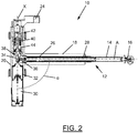
- the spindle drive 12 is surrounded by a tube 18 which is fixedly connected to a housing 20 of the actuator 10.
- the housing 20 is rotatably supported by two bearings 22 relative to a second superordinate assembly (not shown). Furthermore, the actuator is attached to the second superordinate assembly with a second connection unit 24.
- the housing 20 is rotatably but axially fixed relative to the second connection unit 24.
- the output shaft 34 On its side opposite the gear unit 32, the output shaft 34 has a first thread 40 which is in engagement with a corresponding counter thread of an intermediate element 42.
- the intermediate element 42 is at a section which in the in Figure 2 Embodiments shown is arranged at an upper end of the intermediate element 42, rotatably, but axially displaceable, relative to the second connection unit 24.
- a second thread 44 At the other, lower, end of the intermediate element 42 there is a second thread 44, which is in engagement with a corresponding counter thread, which is fixedly connected to the housing 20 or is formed on an inside of the housing 20.
- the first thread 40 here has a significantly smaller thread pitch than the second thread 44.
- the intermediate element 42 Upon rotation of the output shaft 34, the intermediate element 42 becomes axial with respect to the output shaft via the first thread 40 and due to the above-described axial toothing to the second connecting unit 24 34 or in relation to the second connection unit 24. Due to the second thread 44 between the intermediate element 42 and the housing 20, the housing 20 is set in rotation upon a translational displacement of the intermediate element 42.
- the housing 20 rotates about a pivot axis X, which here also forms a central axis of the output shaft 34 and / or the intermediate element 42 and / or the second gear 38.
- the actuator 10 according to the invention can also be designed as a passive unit, that is to say at least without the drive unit 30, in which a rotation of the housing 20 changes the length of the spindle drive 12 or a change in length of the spindle drive 12 rotates the housing 20 relative to the second connection unit 24, for example due to manual actuation.
- An angle ⁇ between the axis A and the pivot axis X is in Figure 2 illustrated embodiment in about 90 °.
- FIG. 3 illustrated storage device 100 is shown as a pivoting element 102 a door.
- FIG. 3 it is irrelevant at this point whether the door 102 is shown completely or only for example a lower one Half of the door 102 in Figure 3 is shown.
- an actuator in particular an actuator 10 according to the above description, is arranged between the door 102 and a section of the vehicle body 106, not shown.
- the actuator 10 aligned parallel to the coupling rods of the four-bar arrangement 104, so that the actuator 10 in the illustration of the Figure 3 can also be a rotary drive with a rigid coupling rod between the rotary drive and the door 102.
- FIG. 3 The state is shown in which the door 102 is pivoted out of an entry opening 108 of a vehicle comprising the vehicle body 106 in order to release the entry opening 108.
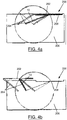
- FIG. 4a and 4b A bearing device 200 is shown, in which the "two-joint" with a fixed coupling rod is replaced by a variable-length actuator 10. Otherwise corresponds to that in the Figures 4a and 4b
- the arrangement 200 shown is a top view of the in FIG Figure 3 shown arrangement 100, to which explicit reference is made at this point. Accordingly, only the differences in the Figures 4a and 4b arrangement 200 to that shown in FIG Figure 3 arrangement 100 shown.
- An actuator 10 according to the invention is connected to the vehicle body 306.
- the actuator 10 is with its free End of the length-adjustable section connected to the vehicle body 306.
- the first connection unit 16 is connected to the vehicle body 306.
- a spacer 310 which is designed here as a rigid rod, is connected at one end to the housing 20 and at its other end to the door 302, wherein it is pivotably mounted on the door 302.
- the length-variable section, for example the spindle drive 12, of the actuator 10 is shortened and the housing 20 rotates relative to it with the spacer 310.
- the door pivots out of the entry opening 308 in accordance with the rotation of the housing 20 and that the housing 20, and thus a pivot axis of the door 302 is simultaneously displaced linearly in accordance with the shortening of the length-adjustable section of the actuator 10. Due to the coupled rotational and translational displacement of the door 302 from the entry opening 308, a larger entry area 308 can be released or closed.
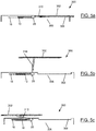
- connection points of the actuators 10 and 10 ′ on the vehicle body 406 coincide.
- the thread pitch directions i.e. the direction of rotation of the threads
- the spindle drives 12 of the actuator 10 and the further actuator 10 ' are opposite, so that when the two length-adjustable sections of the actuators 10 and 10' rotate in the same direction of rotation, one section is lengthened, whereas the other section is shortened becomes.
- the door 402 can be displaced in parallel, that is, an orientation of the door 402 to the vehicle body 406 remains constant during the displacement of the door 402.
- door 402 closes entry opening 408.
- Actuator 10 is fully retracted and further actuator 10 'is fully extended.
- the door 402 is displaced out of the entry opening 408 and is located approximately at half of the displacement area between the maximum positions of the Figures 6a and 6c .
- the variable-length sections of the actuators 10 and 10 ' are in the same position with respect to their variable length.
- the two actuators 10 and 10 ′ are arranged here, for example, on a lower edge of the door 402 and on a floor of the vehicle body 406.
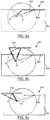
- the two actuators 10 and 10 ' can also be realized by a second embodiment of an actuator 10A according to the invention, which is essentially identical to the actuator 10 according to the invention, but instead of one, two spindle drives, namely a first spindle drive 12A and one second spindle drive 12B.
- gear 38A when gear 38A is driven, gears 36A and 36B are also driven, and in a manner synchronous with rotation of gear 38A, so that first spindle drive 12A and second spindle drive 12B are actuated.
- the two spindle drives 12A and 12B can, for example, have thread pitches that are identical to one another, but which increase in an opposite direction to one another.
- the first spindle drive 12A can be extended by a predetermined distance and the second spindle drive 12B can be shortened by the same distance.
- the two spindle drives 12A and 12B have different thread pitches or sections of thread pitches that are different with respect to one another.
Abstract
Die Erfindung betrifft ein Stellglied (10), umfassend einen Spindelantrieb (12), ein erstes Zahnrad, welches eine translatorische Verlagerung einer mit dem Spindelantrieb (12) verbundenen ersten Verbindungseinheit (16) hervorruft, und ein zweites Zahnrad, welches mit dem ersten Zahnrad in Eingriff steht und welches mit einer zweiten Verbindungseinheit (24) rotatorisch gekoppelt ist, wobei das Stellglied (10) dazu eingerichtet ist, dass eine relative Rotation der beiden Zahnräder zueinander eine Betätigung des Spindelantriebs (12) sowie eine Verlagerung des Spindelantriebs (12) relativ zu der Mittelachse des zweiten Zahnrads hervorruft. Ferner betrifft die Erfindung Lagereinrichtungen eines Schwenkelements, z.B. einer Tür, zu einer übergeordneten Baugruppe, z.B. einer Fahrzeugskarosserie.The invention relates to an actuator (10) comprising a spindle drive (12), a first gear wheel which causes a translational displacement of a first connection unit (16) connected to the spindle drive (12), and a second gear wheel which is connected to the first gear wheel Engagement and which is rotationally coupled to a second connection unit (24), the actuator (10) being set up so that a relative rotation of the two gear wheels relative to one another actuates the spindle drive (12) and displaces the spindle drive (12) relative to one another the central axis of the second gear. The invention further relates to bearing devices of a swivel element, e.g. a door to a higher-level assembly, e.g. a vehicle body.
Description
Die vorliegende Erfindung betrifft ein Stellglied, welches dazu eingerichtet ist, zwei übergeordnete Baugruppen, zwischen welchen das Stellglied angeordnet ist, relativ zueinander zu verlagern.The present invention relates to an actuator which is set up to displace two superordinate assemblies, between which the actuator is arranged, relative to one another.
Derartige Stellglieder sind beispielsweise im Bereich von Fahrzeugtüren, wie Schwenktüren an Bussen, bekannt. Daher wird im Folgenden die Erfindung mit Bezug auf diesen Anwendungsfall beschrieben werden, wobei ausdrücklich darauf hingewiesen wird, dass die Erfindung natürlich nicht darauf zu beschränken ist. Im Bereich von Schwenktüren ist es ferner bekannt, starre Kopplungsstangen einzusetzen, welche einerseits mit einer Karosserie des Fahrzeugs und andererseits mit der Tür verbunden sind. Wird die Tür nun relativ zu der Karosserie verlagert, so folgt die Tür einer durch die Kopplungsstangen vorgegebenen Bahn. Da die Bahn der möglichen Verlagerung der Tür relativ zu der Karosserie zumeist kreisbogenförmig ist, ist der Anbringungspunkt der Kopplungsstangen an der Karosserie dadurch vorbestimmt. Ferner verschwenkt die Tür durch die starre Kopplungsstange meist zuerst weit von der Karosserie weg, bis sie sich in ihrem geöffneten Zustand an die Karosserie anlegt.Actuators of this type are known, for example, in the area of vehicle doors, such as swing doors on buses. Therefore, the invention will be described below with reference to this application, it being expressly pointed out that the invention is of course not to be limited to this. In the area of swing doors it is also known to use rigid coupling rods which are connected on the one hand to a body of the vehicle and on the other hand to the door. If the door is now displaced relative to the body, the door follows a path predetermined by the coupling rods. Since the path of the possible displacement of the door relative to the body is mostly circular, the attachment point of the coupling rods on the body is predetermined. Furthermore, the rigid coupling rod usually first swings the door far away from the body until it lies against the body in its open state.
Es ist daher die Aufgabe der vorliegenden Erfindung, ein Stellglied bereitzustellen, welches es einerseits ermöglicht, eine Baugruppe, wie eine Tür, entlang einer gekrümmten, aber nicht zwangsläufig kreisbogenförmigen, Bahn zu verlagern, und welches es andererseits ermöglicht, den Verbindungspunkt des Stellglied an der Karosserie in einem größeren Bereich anordnen zu können als bei starren Kopplungsstangen.It is therefore the object of the present invention to provide an actuator which, on the one hand, enables an assembly, such as a door, to be displaced along a curved, but not necessarily circular, path, and which, on the other hand, makes it possible to connect the connecting point of the actuator to the To be able to arrange the body in a larger area than with rigid coupling rods.
Diese Aufgabe wird durch ein Stellglied gelöst, umfassend einen Spindelantrieb, welcher eine Spindel und eine mit der Spindel in Gewindeeingriff stehende Spindelmutter umfasst,
ein erstes Zahnrad, welches mit der Spindel oder der Spindelmutter rotatorisch gekoppelt ist,
wobei das jeweils andere aus der Spindelmutter oder der Spindel mit einer ersten Verbindungseinheit zur Verbindung des Stellglieds mit einer ersten übergeordneten Baugruppe verbunden ist,
wobei der Spindelantrieb dazu eingerichtet ist, dass eine Rotation des ersten Zahnrads eine translatorische Verlagerung der ersten Verbindungseinheit hervorruft, und
ein zweites Zahnrad, welches mit dem ersten Zahnrad in Eingriff steht und welches mit einer zweiten Verbindungseinheit zur Verbindung des Stellglieds mit einer zweiten übergeordneten Baugruppe rotatorisch gekoppelt ist, wobei eine Längsachse des Spindelantriebs zu einer Mittelachse, insbesondere zu einer Rotationsachse, des zweiten Zahnrads geneigt ist, wobei das Stellglied dazu eingerichtet ist, dass eine relative Rotation der beiden Zahnräder zueinander eine Betätigung des Spindelantriebs sowie eine Verlagerung des Spindelantriebs relativ zu der Mittelachse des zweiten Zahnrads hervorruft oder eine Betätigung des Spindelantriebs eine relative Rotation der beiden Zahnräder zueinander sowie eine Verlagerung des Spindelantriebs relativ zu der Mittelachse des zweiten Zahnrads hervorruft.This object is achieved by an actuator comprising a spindle drive which has a spindle and one with the spindle in Includes threaded spindle nut,
a first gear wheel which is rotationally coupled to the spindle or the spindle nut,
the other of the spindle nut or the spindle being connected to a first connecting unit for connecting the actuator to a first higher-level assembly,
wherein the spindle drive is set up such that a rotation of the first gear wheel causes a translational displacement of the first connection unit, and
a second gearwheel which engages with the first gearwheel and which is rotationally coupled to a second connecting unit for connecting the actuator to a second superordinate assembly, a longitudinal axis of the spindle drive being inclined to a central axis, in particular to an axis of rotation, of the second gearwheel , wherein the actuator is set up so that a relative rotation of the two gears to one another causes actuation of the spindle drive and a displacement of the spindle drive relative to the central axis of the second gear or an actuation of the spindle drive causes a relative rotation of the two gears to one another and a displacement of the spindle drive relative to the central axis of the second gear.
Ein derartiges Stellglied ermöglicht zwei miteinander kombinierte Bewegungen. Zum einen eine Rotation des Spindelantriebs, und damit der mit dem Spindelantrieb verbundenen ersten übergeordneten Baugruppe, relativ zu der zweiten übergeordneten Baugruppe und zum anderen eine translatorische Verlagerung der ersten übergeordneten Baugruppe relativ zu der Rotationsachse des Spindelantriebs relativ zu der zweiten übergeordneten Baugruppe.Such an actuator enables two combined movements. On the one hand a rotation of the spindle drive, and thus the first higher-level assembly connected to the spindle drive, relative to the second higher-level assembly, and on the other hand a translational displacement of the first higher-level assembly relative to the axis of rotation of the spindle drive relative to the second higher-level assembly.
Insbesondere kann unter einer "Rotation des Spindelantriebs" verstanden werden, dass der gesamte Spindelantrieb bzw. zumindest die Spindel und die Spindelmutter gemeinsam verlagert werden. Ferner kann eine "Rotation des Spindelantriebs" bedeuten, dass eine Mittelachse der Spindel und/oder der Spindelmutter um ein mit der zweiten übergeordneten Baugruppe verbundenes Element, zum Beispiel eine Mittelachse der zweiten Verbindungseinheit oder eine Mittelachse des zweiten Zahnrads, rotiert wird. Ferner sei darauf hingewiesen, dass eine "Neigung" der Längsachse des Spindelantriebs zu der Mittelachse des zweiten Zahnrads jegliche von einer Koaxialität abweichende Neigung, zum Beispiel 30°, 45° oder 90°, umfassen kann.In particular, a "rotation of the spindle drive" can be understood to mean that the entire spindle drive or at least the spindle and the spindle nut are displaced together. Furthermore, a "rotation of the spindle drive "mean that a central axis of the spindle and / or the spindle nut is rotated about an element connected to the second superordinate assembly, for example a central axis of the second connecting unit or a central axis of the second gear wheel. Furthermore, it should be noted that a" Inclination "of the longitudinal axis of the spindle drive to the central axis of the second gear wheel can comprise any inclination deviating from a coaxiality, for example 30 °, 45 ° or 90 °.
Die erste übergeordnete Baugruppe, welche beispielsweise durch eine zu verschwenkende Tür gebildet ist, kann dadurch entlang einer beispielsweise elliptischen Bahn oder entlang einer Kreisbahn, deren Mittelpunkt außerhalb des Stellglieds liegt, verlagert werden. Somit können die beiden Endlagen eines gesamten Verlagerungsbereichs der ersten übergeordneten Baugruppe, zum Beispiel eine erste Endlage, in welcher die Tür einen Durchgangsbereich verschließt, und eine zweite Endlage, in welcher die Tür aus dem Durchgangsbereich heraus verlagert ist und gegen eine Fahrzeugkarosserie anliegt, weiter voneinander beabstandet angeordnet sein. Hierdurch können wiederum größere Durchgangsbereiche realisiert werden.The first higher-level assembly, which is formed, for example, by a door to be pivoted, can thereby be displaced along an, for example, elliptical path or along a circular path, the center of which lies outside the actuator. Thus, the two end positions of an entire displacement area of the first superordinate assembly, for example a first end position in which the door closes a passage area, and a second end position in which the door is displaced out of the passage area and abuts against a vehicle body spaced apart. As a result, larger passage areas can be realized.
Beispielsweise kann wenigstens eines aus dem ersten Zahnrad und dem zweiten Zahnrad ein Kegelzahnrad oder ein Kronenzahnrad sein, welche gemäß der oben beschriebenen "Neigung" zueinander geneigt sein können.For example, at least one of the first gear and the second gear can be a bevel gear or a crown gear, which can be inclined to one another in accordance with the “inclination” described above.
Vorteilhafterweise kann das Stellglied derart ausgebildet sein, dass einer vorbestimmten Aktivierungsstellung des Spindelantriebs genau eine Winkelposition der Verlagerung des Spindelantriebs relativ zu der Mittelachse des zweiten Zahnrads zugeordnet ist und umgekehrt. Auf diese Weise geht eine Verlagerung der Spindel oder der Spindelmutter mit einer zwangsgekoppelten Verlagerung des Spindelantriebs um die Mittelachse des zweiten Zahnrads einher. Das heißt, jedem Winkel des Spindelantriebs um diese Mittelachse ist genau eine Längung des Spindelantriebs zugeordnet. Es kann so verhindert werden, dass die erste Verbindungseinheit bei einem gleichbleibenden Winkel des Spindelantriebs um die Mittelachse, d.h. relativ zu der zweiten übergeordneten Baugruppe, mehr als eine einzige vorbestimmte Position im dreidimensionalen Raum einnimmt.The actuator can advantageously be designed in such a way that a predetermined activation position of the spindle drive is assigned exactly one angular position of the displacement of the spindle drive relative to the central axis of the second gearwheel and vice versa. In this way, a displacement of the spindle or the spindle nut is accompanied by a positively coupled displacement of the spindle drive about the central axis of the second gear. That means every angle of the spindle drive around this central axis is assigned exactly one elongation of the spindle drive. It can thus be prevented that the first connection unit assumes more than a single predetermined position in three-dimensional space at a constant angle of the spindle drive around the central axis, ie relative to the second superordinate assembly.
In einer Weiterbildung der vorliegenden Erfindung kann das zweite Zahnrad mit einem das zweite Zahnrad umgebenden Gehäuse rotatorisch gekoppelt sein, und das Stellglied kann derart ausgebildet sein, dass eine relative Verlagerung der beiden Zahnräder zueinander eine Rotation des Gehäuses relativ zu der zweiten Verbindungseinheit hervorruft. Das bedeutet, dass eine Rotation des zweiten Zahnrads eine Rotation des Gehäuses hervorrufen kann. Ist der Spindelantrieb, welcher beispielsweise ebenfalls in einem Gehäuse angeordnet sein kann, mit dem das zweite Zahnrad umgebenden Gehäuse, zum Beispiel über das Gehäuse des Spindelantriebs, verbunden, so kann die Rotation des Gehäuses auch eine Rotation des Spindelantriebs hervorrufen. Somit kann eine Rotation des zweiten Zahnrads zum einen eine Aktivierung des Spindelantriebs und zum anderen eine Rotation des das zweite Zahnrad umgebenden Gehäuses antreiben.In a development of the present invention, the second gearwheel can be rotationally coupled to a housing surrounding the second gearwheel, and the actuator can be designed such that a relative displacement of the two gearwheels relative to one another causes the housing to rotate relative to the second connection unit. This means that rotation of the second gear can cause the housing to rotate. If the spindle drive, which can also be arranged in a housing, for example, is connected to the housing surrounding the second gear wheel, for example via the housing of the spindle drive, the rotation of the housing can also cause the spindle drive to rotate. Thus, rotation of the second gear can drive activation of the spindle drive and rotation of the housing surrounding the second gear.
Dabei kann zwischen dem zweiten Zahnrad und dem Gehäuse ein Getriebe angeordnet sein, welches zwischen einer Rotation des zweiten Zahnrads und einer Rotation des Gehäuses eine Übersetzung bereitstellt. Durch das Getriebe kann eine erste Rotationsgeschwindigkeit und/oder ein erstes Drehmoment der Rotation des zweiten Zahnrads auf der Zahnradseite des Getriebes in eine zweite Rotationsgeschwindigkeit und/oder in ein zweites Drehmoment auf der Gehäuseseite des Getriebes übersetzt werden.A gear can be arranged between the second gear and the housing, which provides a translation between a rotation of the second gear and a rotation of the housing. The transmission can be used to translate a first rotational speed and / or a first torque of the rotation of the second gear on the gearwheel side of the transmission into a second rotational speed and / or into a second torque on the housing side of the transmission.
Vorteilhafterweise kann das Getriebe über ein eine erste Gewindesteigung aufweisendes erstes Gewinde mit dem zweiten Zahnrad und über ein eine zweite Gewindesteigung aufweisendes zweites Gewinde mit dem Gehäuse in Eingriff stehen, wobei die erste Gewindesteigung von der zweitenAdvantageously, the gear mechanism can engage the second gear wheel via a first thread having a first thread pitch and the housing via a second thread having a second thread pitch, the first thread pitch differing from the second
Gewindesteigung verschieden sein kann. Es ist dadurch möglich, den Spindelantrieb und die Rotation des Gehäuses mit zwei voneinander verschiedenen Rotationsgeschwindigkeiten anzutreiben. Insbesondere sind die Gewindesteigungen derart gewählt, dass eine Rotationsgeschwindigkeit des Gehäuses, und damit gegebenenfalls des Spindelantriebs, relativ zu der zweiten übergeordneten Baugruppe, kleiner ist als eine Rotationsgeschwindigkeit der Spindel oder der Spindelmutter des Spindelantriebs. Durch Festlegen des Verhältnisses der ersten Gewindesteigung zu der zweiten Gewindesteigung kann definiert werden, über welchen Winkelbereich der Spindelantrieb verschwenkt wird, während er sich aus einer ersten, zum Beispiel vollständig eingefahrenen, Endlage in eine zweite, zum Beispiel vollständig ausgefahren, Endlage bewegt. Natürlich ist es sowohl denkbar, dass die beiden Gewinde jeweils konstante, aber gegebenenfalls voneinander verschiedene, Gewindesteigungen aufweisen, als auch dass ein jeweiliges Gewinde Gewindeabschnitte mit variierenden Gewindesteigungen aufweist. Hierdurch kann beispielsweise eine Längung des Spindelantriebs in einem ersten vordefinierten Winkelbereich der Verschwenkung des Spindelantriebs bzw. des Gehäuses relativ zu der zweiten übergeordneten Baugruppe geringer sein als in einem zweiten vordefinierten solchen Winkelbereich.Thread pitch can be different. This makes it possible to drive the spindle drive and the rotation of the housing with two different rotational speeds. In particular, the thread pitches are selected such that a rotational speed of the housing, and thus possibly the spindle drive, relative to the second higher-level assembly is lower than a rotational speed of the spindle or the spindle nut of the spindle drive. By defining the ratio of the first thread pitch to the second thread pitch, it is possible to define the angular range over which the spindle drive is pivoted while it is moving from a first, for example fully retracted, end position to a second, for example fully extended, end position. Of course, it is both conceivable that the two threads each have constant but possibly different thread pitches, and that a respective thread has thread sections with varying thread pitches. In this way, for example, an elongation of the spindle drive in a first predefined angular range of the pivoting of the spindle drive or the housing relative to the second higher-level assembly can be less than in a second predefined such angular range.
Das Getriebe kann ferner ein Zwischenstück umfassen, welches mit dem Gehäuse und dem zweiten Zahnrad in Gewindeeingriff steht, und welches mit der zweiten Verbindungseinheit drehfest, aber axial verlagerbar, gekoppelt ist. Die Anordnung eines Zwischenstücks, welches zwei voneinander getrennte Gewindeabschnitte aufweist, welche voneinander unterschiedliche Gewindesteigungen aufweisen, kann das Vorsehen einer komplexen Getriebeanordnung, wie beispielsweise eines Planetengetriebes, vermeiden. Hierdurch kann sowohl ein benötigter Bauraum als auch eine Fehleranfälligkeit der Anordnung deutlich reduziert werden.The transmission can further comprise an intermediate piece which is in threaded engagement with the housing and the second gearwheel and which is coupled to the second connection unit in a rotationally fixed but axially displaceable manner. The arrangement of an intermediate piece, which has two separate thread sections, which have different thread pitches, can avoid the provision of a complex gear arrangement, such as a planetary gear. As a result, both the installation space required and the susceptibility to errors of the arrangement can be significantly reduced.
Vorteilhafterweise kann das Stellglied eine Antriebseinheit, insbesondere einen Elektromotor, umfassen, welche dazu eingerichtet ist, wenigstens eines aus dem ersten Zahnrad, dem zweiten Zahnrad, der Spindel, der Spindelmutter und dem Gehäuse anzutreiben. Die Antriebseinheit kann dabei dazu eingerichtet sein, ein Aktivierungssignal zu empfangen, welches wenigstens eines aus einer Rotationsrichtung und einer Rotationsgeschwindigkeit angibt, in welcher die Antriebseinheit anzutreiben ist.The actuator can advantageously be a drive unit, in particular an electric motor, which is configured to drive at least one of the first gear, the second gear, the spindle, the spindle nut and the housing. The drive unit can be set up to receive an activation signal, which indicates at least one of a direction of rotation and a rotation speed in which the drive unit is to be driven.
Nachzutragen sei noch, dass es für den Umfang der vorliegenden Erfindung irrelevant ist, ob das zu verschwenkende Element der übergeordneten Baugruppe mit der ersten Verbindungseinheit oder mit der zweiten Verbindungseinheit verbunden ist. Eine Beschreibung einer Ausführungsform, bei welcher das zu verschwenkende Element mit dem längenveränderbaren Abschnitt des Stellglieds verbunden ist, wird weiter unten gegeben.It should also be added that it is irrelevant to the scope of the present invention whether the element of the superordinate assembly to be pivoted is connected to the first connection unit or to the second connection unit. A description of an embodiment in which the element to be pivoted is connected to the length-adjustable section of the actuator is given below.
In einem zweiten Aspekt betrifft die Erfindung eine Lagerungseinrichtung für eine Klappe, insbesondere eine Schwenktür, umfassend eine Viergelenk-Anordnung, welche zwei parallel zueinander und lateral zueinander beabstandet angeordnete Kopplungsstangen umfasst, welche an ihrem jeweiligen einen Ende mit einer übergeordneten Baugruppe, insbesondere einer Fahrzeugkarossiere, schwenkbar verbunden sind, ein Schwenkelement, mit welchem die Kopplungsstangen der Viergelenk-Anordnung, insbesondere einem Rand des Schwenkelements benachbart, an ihrem jeweiligen anderen Ende schwenkbar verbunden sind, und ein Stellglied, insbesondere ein erfindungsgemäßes Stellglied mit einem der voranstehend erwähnten Merkmale, welches an seinem einen Ende mit der übergeordneten Baugruppe schwenkbar verbunden ist und an seinem anderen Ende mit dem Schwenkelement schwenkbar verbunden ist, und welches dazu eingerichtet ist, auf eine Aktivierung des Stellglieds hin, das Schwenkelement relativ zu der übergeordneten Baugruppe zu verlagern.In a second aspect, the invention relates to a mounting device for a flap, in particular a pivoting door, comprising a four-bar arrangement which comprises two coupling rods which are arranged parallel to one another and laterally spaced apart and which at one end have a superordinate assembly, in particular a vehicle body, are pivotally connected, a pivoting element with which the coupling rods of the four-bar arrangement, in particular adjacent to an edge of the pivoting element, are pivotally connected at their respective other ends, and an actuator, in particular an actuator according to the invention with one of the features mentioned above, which on its one end is pivotally connected to the superordinate assembly and is pivotally connected at its other end to the swivel element, and which is set up, upon activation of the actuator, the swivel element relative to the superordinate B to relocate.
Aus dem Stand der Technik sind Schwenkelemente, insbesondere Fahrzeugtüren, bekannt, welche an ihren vertikalen Längsenden über eine jeweilige Viergelenk-Anordnung mit einer Fahrzeugkarosserie verbunden sind. Diese Viergelenk-Anordnungen lassen sich schlecht verkleiden, d.h. in ein Design eines Fahrzeugs einfügen, und nehmen im geschlossenen Zustand mitunter viel Platz im Innenraum eines Fahrzeugs ein. Aufgrund des großen Bauraums einer derartigen Viergelenk-Anordnung, insbesondere bei geschlossener Tür, und einem gewünschten Freifahren eines gesamten Einstiegsbereichs in der Offenposition sind nur geringe Türbreiten realisierbar. Breite Einstiegsbereiche werden oft durch zwei gegenläufige Türen mit jeweiliger Viergelenk-Anordnung realisiert. Gerade im Bereich von geschwungen ausgebildeten Dachkonstruktionen kann eine derartige Viergelenk-Anordnung oft nicht angebracht werden.Swivel elements, in particular vehicle doors, are known from the prior art, which are connected at their vertical longitudinal ends to a vehicle body via a respective four-bar arrangement. These four-joint arrangements are difficult to cover, i.e. insert into a design of a vehicle, and sometimes take up a lot of space in the interior of a vehicle when closed. Because of the large installation space of such a four-bar arrangement, in particular when the door is closed, and a desired opening of an entire entry area in the open position, only small door widths can be realized. Wide entry areas are often realized with two counter-rotating doors, each with a four-bar arrangement. Such a four-bar arrangement can often not be fitted, particularly in the area of curved roof structures.
Der zweite Aspekt der vorliegenden Erfindung kann es nun ermöglichen, auf die obere Viergelenk-Anordnung zu verzichten, das heißt lediglich eine einzige Viergelenk-Anordnung zwischen dem Schwenkelement und der übergeordneten Baugruppe vorzusehen. Das Stellglied kann hier beispielsweise ein, zum Beispiel in einem Gelenk angeordneter, Drehantrieb sein. Dabei kann das Schwenkelement mit den Kopplungsstangen der Viergelenk-Anordnung unter Verwendung von Kugelgelenken verbunden sein, so dass nicht nur eine Verschwenkung zwischen dem Schwenkelement und den Kopplungsstangen, sondern auch eine Verkippung erlaubt ist. Auf diese Weise können Toleranzen und Abweichungen in den Bahnkurven der Viergelenk-Anordnung und des Stellglieds ausgeglichen werden.The second aspect of the present invention can now make it possible to dispense with the upper four-bar arrangement, that is to say to provide only a single four-bar arrangement between the pivoting element and the superordinate assembly. The actuator can be, for example, a rotary drive arranged, for example, in a joint. The pivot element can be connected to the coupling rods of the four-bar arrangement using ball joints, so that not only pivoting between the pivot element and the coupling rods, but also tilting is permitted. In this way, tolerances and deviations in the trajectories of the four-bar arrangement and the actuator can be compensated.
Es sei an dieser Stelle explizit nochmals darauf hingewiesen, dass die Merkmale und Vorteile des beschriebenen erfindungsgemäßen Stellglieds auf die Lagerungseinrichtung gleichermaßen Anwendung finden und umgekehrt.At this point it should be explicitly pointed out again that the features and advantages of the actuator according to the invention described apply equally to the bearing device and vice versa.
Ferner kann das Stellglied eine Kopplungsstange umfassen, welche parallel zu den Kopplungsstangen der Viergelenk-Anordnung und lateral zu diesen beabstandet, insbesondere zu diesen gleich beabstandet, angeordnet ist. Bei einer Anordnung der Kopplungsstange, in einer vertikalen Richtung gesehen bzw. entlang einer horizontalen Richtung, zwischen den Kopplungsstangen der Viergelenk-Anordnung ist es möglich, einen für eine Lagerung des Schwenkelements an der übergeordneten Baugruppe benötigten Bauraum zu reduzieren.Furthermore, the actuator can comprise a coupling rod, which is parallel to the coupling rods of the four-bar arrangement and laterally spaced apart, in particular equally spaced apart. When the coupling rod is arranged, seen in a vertical direction or along a horizontal direction, between the coupling rods of the four-bar arrangement, it is possible to reduce the installation space required for mounting the pivot element on the superordinate assembly.
Insbesondere können die beiden Kopplungsstangen der Viergelenk-Anordnung oder die beiden Kopplungsstangen der Viergelenk-Anordnung und die Kopplungsstange des Stellglieds eine gleiche Länge aufweisen. Werden nun Verbindungspunkte aller Kopplungsstangen an der übergeordneten Baugruppe und/oder an dem Schwenkelement auf einer gemeinsamen, vorzugsweise vertikalen, Ebene angeordnet, so kann es ermöglicht werden, dass das Schwenkelement während des Verschwenkens parallel zu dieser Ebene ausgerichtet verbleibt. In anderen Worten kann so vermieden werden, dass sich das Schwenkelement aus einer z.B. vertikalen Ausrichtung heraus neigt.In particular, the two coupling rods of the four-bar arrangement or the two coupling rods of the four-bar arrangement and the coupling rod of the actuator can have the same length. If connection points of all coupling rods on the superordinate assembly and / or on the swivel element are now arranged on a common, preferably vertical, plane, it can be made possible for the swivel element to remain aligned parallel to this plane during the swiveling. In other words, it can be avoided in this way that the swivel element is made of e.g. vertical alignment tends out.
Das Stellglied kann, in einem betriebsbereiten Zustand der Lagerungseinrichtung, vertikal oberhalb der Viergelenk-Anordnung, insbesondere im Bereich der Hälfte einer vertikalen Erstreckung des Schwenkelements, angeordnet sein. Beispielsweise kann die Viergelenk-Anordnung im Bereich eines Bodens eines Fahrzeugs angeordnet sein, so dass die Viergelenk-Anordnung ausreichend Bauraum in Anspruch nehmen kann, ohne einen Fahrgastraum oder/und ein äußeres Design des Fahrzeugs zu beeinträchtigen. Die Viergelenk-Anordnung kann daher sehr stabil ausgeführt werden, so dass sie das Gewicht eines zu verschwenkenden Elements zum Beispiel vollständig tragen kann. Dem Stellglied kann nun lediglich die Aufgabe zugeteilt sein, das zu verschwenkende Element anzutreiben und es dabei an einem Verkippen aus einer vordefinierten Ausrichtung heraus zu hindern. Entsprechend kann das Stellglied platzsparend ausgebildet sein.When the bearing device is ready for operation, the actuator can be arranged vertically above the four-bar arrangement, in particular in the region of half of a vertical extent of the pivoting element. For example, the four-bar arrangement can be arranged in the area of a floor of a vehicle, so that the four-bar arrangement can take up sufficient installation space without impairing a passenger compartment and / or an external design of the vehicle. The four-bar arrangement can therefore be made very stable, so that it can, for example, fully support the weight of an element to be pivoted. The actuator can now only be assigned the task of driving the element to be pivoted and thereby preventing it from tilting out of a predefined orientation. The actuator can accordingly be designed to save space.
Die erfindungsgemäße Lagerungseinrichtung könnte anstelle für eine Schwenktür auch z.B. für ein Fenster oder ähnliches ausgelegt sein.The storage device according to the invention could also e.g. be designed for a window or the like.
In einem dritten Aspekt der vorliegenden Erfindung betrifft die Erfindung eine Lagerungseinrichtung für eine Klappe, insbesondere eine Schwenktür, umfassend
ein Stellglied, insbesondere ein erfindungsgemäßes Stellglied mit einem der voranstehend erwähnten Merkmale, welches an seinem einen Ende mit einer übergeordneten Baugruppe, insbesondere einer Fahrzeugkarossiere, schwenkbar verbunden ist, und
ein Schwenkelement, mit welchem das andere Ende des Stellglieds, insbesondere einem Rand des Schwenkelements benachbart, schwenkbar verbunden ist,
wobei das Stellglied dazu eingerichtet ist, auf eine Aktivierung hin, eine kombinierte Längenänderung eines ersten Abschnitts und eine relative Rotation des sich längenveränderbaren Abschnitts relativ zu einem einem Ende des längenveränderbaren Abschnitts zugeordneten zweiten Abschnitt des Stellglieds durchzuführen, um das Schwenkelement relativ zu der übergeordneten Baugruppe zu verlagern,
wobei das Stellglied derart ausgebildet ist, dass einer vorbestimmten Aktivierungsstellung des längenveränderbaren Abschnitts genau eine Winkelposition der Verlagerung des längenveränderbaren Abschnitts relativ zu einer Schwenkachse des längenveränderbaren Abschnitts zugeordnet ist und umgekehrt.In a third aspect of the present invention, the invention relates to a mounting device for a flap, in particular a swing door, comprising
an actuator, in particular an actuator according to the invention with one of the features mentioned above, which is pivotally connected at one end to a superordinate assembly, in particular a vehicle body, and
a swivel element with which the other end of the actuator, in particular adjacent to an edge of the swivel element, is pivotally connected,
the actuator being configured, upon activation, to perform a combined length change of a first portion and a relative rotation of the length-adjustable portion relative to a second portion of the actuator associated with one end of the length-adjustable portion to pivot the pivot member relative to the parent assembly relocate
wherein the actuator is designed such that a predetermined activation position of the variable-length section is assigned exactly one angular position of the displacement of the variable-length section relative to a pivot axis of the variable-length section and vice versa.
Obwohl es für den Umfang des dritten Aspekts der vorliegenden Erfindung lediglich erforderlich ist, dass das Stellglied eine Zwangskopplung zwischen der Längenänderung des ersten Abschnitts und der Verschwenkung des ersten Abschnitts um die Schwenkachse aufweist, wird das Stellglied im Folgenden an dem Beispiel des erfindungsgemäßen Stellglieds nach dem ersten Aspekt der vorliegenden Erfindung beschrieben werden.Although it is only necessary for the scope of the third aspect of the present invention that the actuator has a positive coupling between the change in length of the first section and the pivoting of the first section about the pivot axis, the actuator is described below using the example of the actuator according to the invention first aspect of the present invention.
Natürlich ist es ebenfalls denkbar, dass anstatt des Spindelantriebs ein beispielsweise hydraulisch, pneumatisch oder magnetisch betriebener Antrieb vorgesehen ist, dessen Aktivierung nicht mechanisch, sondern beispielsweise unter Verwendung einer geeigneten Messvorrichtung, gekoppelt ist.Of course, it is also conceivable that instead of the spindle drive, for example, a hydraulically, pneumatically or magnetically operated drive is provided, the activation of which is not coupled mechanically but, for example, using a suitable measuring device.
Ferner sei erwähnt, dass die "Verlagerung des längenveränderbaren Abschnitts relativ zu einer Schwenkachse des längenveränderbaren Abschnitts" nicht zwangsläufig bedeuten muss, dass es der längenveränderbare Abschnitt des Stellglieds ist, welcher sichtbar verschwenkt wird. Beispielsweise kann der längenveränderbare Abschnitt mit einer Fahrzeugkarosserie verbunden sein und ein nicht längenveränderbarer Abschnitt des Stellglieds wird verschwenkt. Entscheidend ist, dass zwischen einem längenveränderbaren Abschnitt des Stellglieds und einem weiteren Abschnitt des Stellglieds eine relative Rotation durchgeführt wird, während der längenveränderbare Abschnitt aktiviert, das heißt in seiner Länge verändert, wird.It should also be mentioned that the "displacement of the length-adjustable section relative to a pivot axis of the length-adjustable section" does not necessarily mean that it is the length-adjustable section of the actuator which is visibly pivoted. For example, the length-variable section can be connected to a vehicle body and a non-length-variable section of the actuator is pivoted. It is crucial that a relative rotation is carried out between a length-adjustable section of the actuator and a further section of the actuator while the length-variable section is activated, that is to say changed in length.
Durch die Verwendung eines Stellglieds, welches eine Zwangskopplung zwischen seiner Längenänderung und seiner Rotation aufweist, ist es möglich, den Verbindungspunkt des Stellglieds zu der übergeordneten Baugruppe nahezu beliebig zu variieren. Dennoch kann eine zum Beispiel zu einer Außenfläche der übergeordneten Baugruppe parallele Verlagerung des Schwenkelements durchgeführt werden.By using an actuator which has a positive coupling between its change in length and its rotation, it is possible to vary the connection point of the actuator to the superordinate assembly almost as desired. Nevertheless, the swivel element can be displaced parallel to an outer surface of the superordinate assembly, for example.
In einer Weiterbildung der vorliegenden Erfindung kann das Stellglied an seinem dem längenveränderbaren Abschnitt zugeordneten Ende mit der übergeordneten Baugruppe verbunden sein und einen zwischen dem längenveränderbaren Abschnitt des Stellglieds und dem Schwenkelement angeordneten Abstandhalter umfassen. Beispielsweise kann ein Spindelantrieb des Stellglieds mit der Fahrzeugkarosserie derart verbunden sein, dass auf eine Aktivierung des Spindelantriebs hin das mit dem Abstandhalter verbundene Ende des Spindelantriebs relativ zu der Fahrzeugkarosserie verlagert wird. Dabei wird der Abstandshalter, welcher beispielsweise durch eine starre Stange gebildet ist, relativ zu dem Spindelantrieb rotiert. Eine derartige Anordnung kann zur Folge haben, dass ein Rotationsmittelpunkt des Abstandhalters gemäß der Längenänderung des Spindelantriebs linear verlagert wird. Auf diese Weise kann ein Schwenkelement, wie beispielsweise eine Tür, nicht nur gemäß dem durch die Rotation des Abstandhalters definierten Verschwenkungsbereich, sondern auch gemäß dem Hub des Spindelantriebs verlagert werden. Da sich der Drehpunkt des Scharniers verlagert, kann sich eine Vergrößerung eines möglichen Einstiegsbereichs ergeben, welcher durch das Öffnen der Tür freigegeben wird.In a development of the present invention, the actuator can be connected at its end assigned to the length-adjustable section to the higher-level assembly and can comprise a spacer arranged between the length-adjustable section of the actuator and the swivel element. For example, a The spindle drive of the actuator can be connected to the vehicle body in such a way that, when the spindle drive is activated, the end of the spindle drive connected to the spacer is displaced relative to the vehicle body. The spacer, which is formed, for example, by a rigid rod, is rotated relative to the spindle drive. Such an arrangement can result in a center of rotation of the spacer being linearly displaced in accordance with the change in length of the spindle drive. In this way, a swivel element, such as a door, can be displaced not only according to the swivel range defined by the rotation of the spacer, but also according to the stroke of the spindle drive. Since the pivot point of the hinge shifts, there may be an enlargement of a possible entry area, which is released by opening the door.
Natürlich können zwischen dem Schwenkelement und der Fahrzeugkarosserie zur weiteren Lagerung und Abstützung weitere Kopplungsstangen vorgesehen sein, zum Beispiel in Form einer Viergelenk-Anordnung.Of course, further coupling rods can be provided between the pivoting element and the vehicle body for further storage and support, for example in the form of a four-bar arrangement.
In einer besonderen Ausführungsform der vorliegenden Erfindung kann die Lagerungseinrichtung ein weiteres Stellglied umfassen, insbesondere ein erfindungsgemäßes Stellglied mit einem der voranstehend erwähnten Merkmale, welches an seinem einen Ende mit der übergeordneten Baugruppe und an seinem anderen Ende mit dem Schwenkelement schwenkbar verbunden ist,
wobei das weitere Stellglied dazu eingerichtet sein kann, auf eine Aktivierung hin, eine kombinierte Längenänderung eines ersten Abschnitts und eine relative Rotation des sich längenveränderbaren Abschnitts relativ zu einem einem Ende des längenveränderbaren Abschnitts zugeordneten zweiten Abschnitt des weiteren Stellglieds durchzuführen, um das Schwenkelement relativ zu der übergeordneten Baugruppe zu verlagern,
wobei das weitere Stellglied derart ausgebildet sein kann, dass einer vorbestimmten Aktivierungsstellung des längenveränderbaren Abschnitts genau eine Winkelposition der Verlagerung des längenveränderbaren Abschnitts relativ zu einer Schwenkachse des längenveränderbaren Abschnitts zugeordnet ist und umgekehrt.In a special embodiment of the present invention, the bearing device can comprise a further actuator, in particular an actuator according to the invention with one of the features mentioned above, which is pivotally connected at one end to the superordinate assembly and at its other end to the pivot element,
wherein the further actuator may be configured, upon activation, to perform a combined length change of a first section and a relative rotation of the length-adjustable section relative to a second section of the further actuator assigned to one end of the length-adjustable section in order to perform the pivoting element relative to the to move the superordinate assembly,
wherein the further actuator can be designed such that a predetermined activation position of the length-adjustable section is assigned exactly one angular position of the displacement of the length-adjustable section relative to a pivot axis of the length-adjustable section and vice versa.
Durch die Anordnung von zwei voranstehend erwähnten zwangsgekoppelten Stellgliedern kann auf die Anordnung von weiteren Kopplungsstangen und/oder Viergelenk-Anordnungen vollständig verzichtet werden. Ferner kann dadurch ermöglicht werden, eine Tür maximal aus einem Einstiegsbereich zu verlagern. Bei geeigneter Auswahl des Verhältnisses von Rotation zu Längenänderung des jeweiligen Stellglieds kann eine Anbindung des jeweiligen Stellglieds an der übergeordneten Baugruppe nahezu frei gewählt werden.Due to the arrangement of two positively coupled actuators mentioned above, the arrangement of further coupling rods and / or four-joint arrangements can be dispensed with entirely. It can also make it possible to move a door at most from an entry area. With a suitable selection of the ratio of rotation to change in length of the respective actuator, a connection of the respective actuator to the superordinate assembly can be chosen almost freely.
Vorteilhafterweise kann eine Gewindesteigungsrichtung einer Spindel eines ersten Spindelantriebs des einen Stellglieds zu einer Gewindesteigungsrichtung einer Spindel eines zweiten Spindelantriebs des weiteren Stellglieds gegenläufig sein. Insbesondere kann dadurch ermöglicht werden, dass die Anbindungspunkte der beiden Stellglieder auf einer gemeinsamen, insbesondere zu einer Haupterstreckungsrichtung des Schwenkelements parallelen, beispielsweise vertikalen, Achse liegen. Es kann so eine Parallelverfahrung des Schwenkelements zu der übergeordneten Baugruppe erreicht werden. Über einen Verschwenkungsbereich des Schwenkelements, zum Beispiel der Tür, hinweg kann somit der längenveränderbare Abschnitt des einen Stellglieds verkürzt werden, während gleichzeitig der längenveränderbare Abschnitt des weiteren Stellglieds verlängert wird.Advantageously, a thread pitch direction of a spindle of a first spindle drive of the one actuator can be opposite to a thread pitch direction of a spindle of a second spindle drive of the further actuator. In particular, this can make it possible for the connection points of the two actuators to lie on a common, in particular vertical, axis, in particular parallel to a main direction of extension of the pivoting element. In this way, parallel movement of the swivel element to the higher-level assembly can be achieved. The length-adjustable section of the one actuator can thus be shortened over a pivoting area of the swivel element, for example the door, while at the same time the length-adjustable section of the further actuator is lengthened.
Auch hier könnte die erfindungsgemäße Lagerungseinrichtung anstelle für eine Schwenktür auch z.B. für ein Fenster oder ähnliches ausgelegt sein.Here, too, the storage device according to the invention could also be e.g. be designed for a window or the like.
Im Folgenden wird die vorliegende Erfindung anhand von
Ausführungsbeispielen mit Bezug auf die begleitenden Zeichnungen in größerem Detail beschrieben werden, in welchen
Figur 1- eine perspektivische Ansicht einer Ausführungsform eines erfindungsgemäßen Stellglieds darstellt;
Figur 2- eine Seitenquerschnittsansicht des erfindungsgemäßen Stellglieds aus
Figur 1 darstellt; - Figur 3
- eine schematische Ansicht eines Abschnitts einer Schwenktür in einer ersten Ausführungsform darstellt;
- Figur 4a
- eine schematische Ansicht eines Abschnitts einer Schwenktür in einer zweiten Ausführungsform und einer ersten Positionierung darstellt;
- Figur 4b
- eine schematische Ansicht eines Abschnitts einer Schwenktür in der zweiten Ausführungsform von
Figur 4a und einer zweiten Positionierung darstellt; - Figuren 5a bis 5c
- schematische Ansichten einer erfindungsgemäßen Lagerungseinrichtung in unterschiedlichen Positionierungen darstellen;
- Figuren 6a bis 6c
- schematische Ansichten einer weiteren erfindungsgemäßen Lagerungseinrichtung in unterschiedlichen Positionierungen darstellen;
- Figur 7
- eine Aufsicht einer zweiten Ausführungsform eines erfindungsgemäßen Stellglieds darstellt; und
- Figur 8
- eine Seitenquerschnittsansicht des erfindungsgemäßen Stellglieds aus
Figur 7 darstellt;
Embodiments are described in greater detail with reference to the accompanying drawings, in which
- Figure 1
- a perspective view of an embodiment of an actuator according to the invention;
- Figure 2
- a side cross-sectional view of the actuator according to the invention
Figure 1 represents; - Figure 3
- Figure 3 is a schematic view of a portion of a swing door in a first embodiment;
- Figure 4a
- is a schematic view of a portion of a swing door in a second embodiment and a first positioning;
- Figure 4b
- is a schematic view of a portion of a swing door in the second embodiment of
Figure 4a and a second positioning; - Figures 5a to 5c
- represent schematic views of a storage device according to the invention in different positions;
- Figures 6a to 6c
- represent schematic views of a further storage device according to the invention in different positions;
- Figure 7
- a top view of a second embodiment of an actuator according to the invention; and
- Figure 8
- a side cross-sectional view of the invention Actuator
Figure 7 represents;
In
An seinem der ersten Verbindungseinheit 16 entgegengesetzten Ende ist der Spindelantrieb 12 von einem Rohr 18 umgeben, welches mit einem Gehäuse 20 des Stellglieds 10 fest verbunden ist. Das Gehäuse 20 ist relativ zu einer zweiten übergeordneten Baugruppe (nicht dargestellt) durch zwei Lager 22 drehbar gelagert. Ferner ist das Stellglied mit einer zweiten Verbindungseinheit 24 an der zweiten übergeordneten Baugruppe befestigt. Das Gehäuse 20 ist relativ zu der zweiten Verbindungseinheit 24 drehbar aber axialfest gelagert.At its end opposite the
In dem in
In
Ein mit der Spindel 28 drehfest verbundenes erstes Zahnrad 36 ist mit einem mit der Abtriebswelle 34 drehfest verbundenen zweiten Zahnrad 38 in Eingriff. Treibt die Antriebseinheit 30 nun die Abtriebswelle 34 und damit das zweite Zahnrad 38 an, so wird das erste Zahnrad 36 zusammen mit der Spindel 28 in Rotation versetzt. Hierdurch wird, wie voranstehend erwähnt, die Spindelmutter 26 entlang einer Achse A, welche hier auch eine Mittelachse der Spindel 28 bildet, verlagert.A
An ihrem der Getriebeeinheit 32 entgegengesetzten Seite weist die Abtriebswelle 34 ein erstes Gewinde 40 auf, welches mit einem entsprechenden Gegengewinde eines Zwischenelements 42 in Eingriff steht. Das Zwischenelement 42 ist an einem Abschnitt, welcher in der in
Das erste Gewinde 40 weist hier eine deutlich kleinere Gewindesteigung auf als das zweite Gewinde 44. Auf eine Rotation der Abtriebswelle 34 hin wird das Zwischenelement 42 über das erste Gewinde 40 und aufgrund der oben beschriebenen Axialverzahnung zu der zweiten Verbindungseinheit 24 axial in Bezug auf die Abtriebswelle 34 bzw. in Bezug auf die zweite Verbindungseinheit 24 verlagert. Aufgrund des zweiten Gewindes 44 zwischen dem Zwischenelement 42 und dem Gehäuse 20 wird auf eine translatorische Verlagerung des Zwischenelements 42 hin das Gehäuse 20 in Rotation versetzt. Das Gehäuse 20 rotiert dabei um eine Schwenkachse X, welche hier zugleich eine Mittelachse der Abtriebswelle 34 und/oder des Zwischenelements 42 und/oder des zweiten Zahnrads 38 bildet.The
Im Ergebnis bedeutet das, dass eine Aktivierung der Antriebseinheit 30 eine Rotation der Abtriebswelle 34 und des damit verbundenen Zahnrads 38 hervorruft, wodurch zum einen über das erste Zahnrad 36 der Spindelantrieb 12 aktiviert, das heißt verlängert oder verkürzt wird, und zum anderen das Rohr 18 zusammen mit dem Spindelantrieb 12 und dem Gehäuse 20 relativ zu der zweiten Verbindungseinheit 24 um die Schwenkachse X verschwenkt wird.As a result, this means that activation of the
Es sei nochmals darauf hingewiesen, dass hierdurch eine Zwangskopplung entsteht, so dass eine Längenänderung des Spindelantriebs 12 nicht ohne eine Rotation des Gehäuses 20, und umgekehrt, durchgeführt werden kann. Ferner bedeutet das, dass je nach Auswahl des ersten Gewindes 40, des zweiten Gewindes 44, der beiden Zahnräder 36, 38 und/oder des Spindelantriebs 12 einem jeden Winkel des Gehäuses 20 relativ zu der zweiten Verbindungseinheit 24 exakt eine Längenposition des Spindelantriebs 12 zugeordnet ist.It should be pointed out again that this creates a positive coupling, so that a change in length of the
Selbstverständlich kann das erfindungsgemäße Stellglied 10 auch als passive Einheit, das heißt zumindest ohne die Antriebseinheit 30, ausgebildet sein, bei welcher eine Rotation des Gehäuses 20 eine Längenänderung des Spindelantriebs 12 oder eine Längenänderung des Spindelantriebs 12 eine Rotation des Gehäuses 20 relativ zu der zweiten Verbindungseinheit 24, beispielsweise aufgrund manueller Betätigung, hervorruft.Of course, the
Ein Winkel α zwischen der Achse A und der Schwenkachse X beträgt in dem in
In der in
Die Tür 102 ist mit einer Viergelenk-Anordnung 104 mit einer Fahrzeugkarosserie 106 verbunden. Die Viergelenk-Anordnung 104 ist hier aus zwei identischen und parallel zueinander angeordneten Kopplungsstangen gebildet. Die Viergelenk-Anordnung 104 ist an der Fahrzeugkarosserie 106 derart angelenkt, dass die Kopplungsstangen der Viergelenk-Anordnung 104 relativ zu der Fahrzeugkarosserie 106 entlang nur einer einzigen, beispielsweise horizontalen, Ebene verschwenken können.The
An einer vertikal höher gelegenen Position der Tür 102 ist zwischen der Tür 102 und einem nicht dargestellten Abschnitt der Fahrzeugkarosserie 106 ein Stellglied, insbesondere ein Stellglied 10 gemäß der voranstehenden Beschreibung, angeordnet. Dabei ist in
In
In den
Im Gegensatz zu der Lagerungseinrichtung 100 kann das Stellglied 10 der Lagerungseinrichtung 200 an einer nahezu beliebigen Stelle mit der Fahrzeugkarosserie 206 verbunden werden. In dem in den
In
In
Die
Mit der Fahrzeugkarosserie 306 ist ein erfindungsgemäßes Stellglied 10, wie oben beschrieben, verbunden. Dabei ist das Stellglied 10 mit seinem freien Ende des längenveränderbaren Abschnitts mit der Fahrzeugkarosserie 306 verbunden. Mit Bezug auf die in
Auf eine Aktivierung des Stellglieds 10 hin, welche eine zwangsgekoppelte Längenänderung des längenveränderbaren Abschnitts und eine Rotation des Gehäuses 20, und damit des Abstandhalters 310, hervorruft, wird, in der Abfolge der
Zur Stabilisierung der Tür 302 kann es beispielsweise denkbar sein, zwei Stellglieder 10 anzuordnen.To stabilize the
Die
Die beiden Stellglieder 10 und 10' sind mit ihrem längenveränderbaren Abschnitt, welcher in dem hier dargestellten Ausführungsbeispiel durch den Spindelantrieb 12 ausgebildet ist, zwischen der Fahrzeugkarosserie 406 und der Tür 402 angeordnet. Der Spindelantrieb 12 des Stellglieds 10 ist dabei an einem Rand der Tür 402 angelenkt, wohingegen der Spindelantrieb 12 des weiteren Stellglieds 10' im Bereich einer Mitte der Tür 402 angelenkt ist.The length-adjustable section of the two
In dem besonderen Ausführungsbeispiel, welches in den
Die Gewindesteigungsrichtungen, d.h. der Drehsinn der Gewinde, der Spindelantriebe 12 des Stellglieds 10 und des weiteren Stellglieds 10' sind gegensätzlich, so dass bei einer Rotation der beiden längenveränderbaren Abschnitte der Stellglieder 10 und 10' in dem gleichen Drehsinn der eine Abschnitt verlängert wird, wohingegen der andere Abschnitt verkürzt wird. Im Falle einer identischen Gewindesteigungshöhe der beiden Gewinde der Stellglieder 10 und 10' kann so die Tür 402 parallel verlagert werden, das heißt, eine Orientierung der Tür 402 zu der Fahrzeugkarosserie 406 bleibt während der Verlagerung der Tür 402 konstant.The thread pitch directions, i.e. the direction of rotation of the threads, the spindle drives 12 of the
In der
In der
In der
Die beiden Stellglieder 10 und 10' sind hier beispielsweise an einem unteren Rand der Tür 402 und an einem Boden der Fahrzeugkarosserie 406 angeordnet.The two
Wie in
Aus diesem Grund sei an dieser Stelle in Bezug auf das Stellglied 10A explizit auf die Ausführungen zu dem Stellglied 10 bzw. 10' verwiesen. Im Folgenden werden daher lediglich die Unterschiede des Stellglieds 10A zu dem Stellglied 10 bzw. 10' beschrieben werden.For this reason, reference is made here explicitly to the explanations regarding the
Wie in der Seitenquerschnittsansicht von
Das bedeutet, dass, wenn das Zahnrad 38A angetrieben wird, die Zahnräder 36A und 36B ebenfalls und in einer relativ zu einer Rotation des Zahnrads 38A synchronen Weise, angetrieben werden, so dass der erste Spindelantrieb 12A und der zweite Spindelantrieb 12B betätigt werden.That is, when
Die beiden Spindelantriebe 12A und 12B können beispielsweise zueinander gleiche Gewindesteigungen aufweisen, welche jedoch in einer zueinander entgegengesetzten Richtung ansteigen. Somit kann auf eine Rotation des Zahnrads 38A hin zum Beispiel der erste Spindelantrieb 12A um einen vorbestimmten Weg verlängert und der zweite Spindelantrieb 12B um den gleichen Weg verkürzt werden.The two spindle drives 12A and 12B can, for example, have thread pitches that are identical to one another, but which increase in an opposite direction to one another. Thus, upon rotation of the
Natürlich ist es ebenfalls denkbar, dass die beiden Spindelantriebe 12A und 12B zueinander unterschiedliche Gewindesteigungen bzw. Abschnitte von in Bezug aufeinander unterschiedlichen Gewindesteigungen aufweisen.Of course, it is also conceivable that the two spindle drives 12A and 12B have different thread pitches or sections of thread pitches that are different with respect to one another.
Claims (15)
einen Spindelantrieb (12, 12A, 12B), welcher eine Spindel (28) und eine mit der Spindel (28) in Gewindeeingriff stehende Spindelmutter (26) umfasst,
ein erstes Zahnrad (36), welches mit der Spindel (28) oder der Spindelmutter (26) rotatorisch gekoppelt ist,
wobei das jeweils andere aus der Spindelmutter (26) oder der Spindel (28) mit einer ersten Verbindungseinheit (16) zur Verbindung des Stellglieds (10, 10A) mit einer ersten übergeordneten Baugruppe (102, 202, 302, 402; 106, 206, 306, 406) verbunden ist,
wobei der Spindelantrieb (12, 12A, 12B) dazu eingerichtet ist, dass eine Rotation des ersten Zahnrads (36) eine translatorische Verlagerung der ersten Verbindungseinheit (16) hervorruft, und
ein zweites Zahnrad (38), welches mit dem ersten Zahnrad (36) in Eingriff steht und welches mit einer zweiten Verbindungseinheit (24) zur Verbindung des Stellglieds (10, 10A) mit einer zweiten übergeordneten Baugruppe (106, 206, 306, 406; 102, 202, 302, 402) rotatorisch gekoppelt ist,
wobei eine Längsachse (A) des Spindelantriebs (12, 12A, 12B) zu einer Mittelachse (X), insbesondere zu einer Rotationsachse (X), des zweiten Zahnrads (38) geneigt ist,
wobei das Stellglied (10, 10A) dazu eingerichtet ist, dass eine relative Rotation der beiden Zahnräder (36, 38) zueinander eine Betätigung des Spindelantriebs (12, 12A, 12B) sowie eine Verlagerung des Spindelantriebs (12, 12A, 12B) relativ zu der Mittelachse (X) des zweiten Zahnrads (38) hervorruft oder eine Betätigung des Spindelantriebs (12, 12A, 12B) eine relative Rotation der beiden Zahnräder (36, 38) zueinander sowie eine Verlagerung des Spindelantriebs (12, 12A, 12B) relativ zu der Mittelachse (X) des zweiten Zahnrads (38) hervorruft.Actuator (10, 10A) comprising
a spindle drive (12, 12A, 12B) which comprises a spindle (28) and a spindle nut (26) which is in threaded engagement with the spindle (28),
a first gear wheel (36) which is rotationally coupled to the spindle (28) or the spindle nut (26),
the other of the spindle nut (26) or the spindle (28) having a first connecting unit (16) for connecting the actuator (10, 10A) to a first higher-level assembly (102, 202, 302, 402; 106, 206, 306, 406) is connected,
wherein the spindle drive (12, 12A, 12B) is set up so that rotation of the first gear (36) causes a translational displacement of the first connecting unit (16), and
a second gear (38) which is in engagement with the first gear (36) and which has a second connecting unit (24) for connecting the actuator (10, 10A) to a second superordinate assembly (106, 206, 306, 406; 102, 202, 302, 402) is rotationally coupled,
a longitudinal axis (A) of the spindle drive (12, 12A, 12B) being inclined to a central axis (X), in particular to an axis of rotation (X), of the second gear wheel (38),
the actuator (10, 10A) being set up so that a relative rotation of the two gear wheels (36, 38) relative to one another actuates the spindle drive (12, 12A, 12B) and displaces the spindle drive (12, 12A, 12B) relative to one another the center axis (X) of the second gear wheel (38) or actuation of the spindle drive (12, 12A, 12B) causes a relative rotation of the two gear wheels (36, 38) to one another and a displacement of the spindle drive (12, 12A, 12B) relative to one another the central axis (X) of the second gear (38).
dadurch gekennzeichnet, dass das Stellglied (10, 10A) derart ausgebildet ist, dass einer vorbestimmten Aktivierungsstellung des Spindelantriebs (12, 12A, 12B) genau eine Winkelposition der Verlagerung des Spindelantriebs (12, 12A, 12B) relativ zu der Mittelachse (X) des zweiten Zahnrads (38) zugeordnet ist und umgekehrt.Actuator (10, 10A) according to claim 1,
characterized in that the actuator (10, 10A) is designed such that a predetermined activation position of the spindle drive (12, 12A, 12B) exactly one angular position of the displacement of the spindle drive (12, 12A, 12B) relative to the central axis (X) of the second gear (38) is assigned and vice versa.
dadurch gekennzeichnet, dass das zweite Zahnrad (38) mit einem das zweite Zahnrad (38) umgebenden Gehäuse (20) rotatorisch gekoppelt ist, und dass das Stellglied (10, 10A) derart ausgebildet ist, dass eine relative Verlagerung der beiden Zahnräder (36, 38) zueinander eine Rotation des Gehäuses (20) relativ zu der zweiten Verbindungseinheit (24) hervorruft.Actuator (10, 10A) according to claim 1 or 2,
characterized in that the second gearwheel (38) is rotationally coupled to a housing (20) surrounding the second gearwheel (38), and in that the actuator (10, 10A) is designed such that a relative displacement of the two gearwheels (36, 38) relative to one another causes the housing (20) to rotate relative to the second connecting unit (24).
dadurch gekennzeichnet, dass zwischen dem zweiten Zahnrad (38) und dem Gehäuse (20) ein Getriebe angeordnet ist, welches zwischen einer Rotation des zweiten Zahnrads (38) und einer Rotation des Gehäuses (20) eine Übersetzung bereitstellt.Actuator (10, 10A) according to claim 3,
characterized in that between the second gear (38) and the housing (20) a gear is arranged, which provides a translation between a rotation of the second gear (38) and a rotation of the housing (20).
dadurch gekennzeichnet, dass das Getriebe über ein eine erste Gewindesteigung aufweisendes erstes Gewinde (40) mit dem zweiten Zahnrad (38) und über ein eine zweite Gewindesteigung aufweisendes zweites Gewinde (44) mit dem Gehäuse (20) in Eingriff steht, wobei die erste Gewindesteigung von der zweiten Gewindesteigung verschieden ist.Actuator (10, 10A) according to claim 4,
characterized in that the gear is in engagement with the second gear (38) via a first thread (40) having a first thread pitch and with the housing (20) via a second thread (44) having a second thread pitch, the first thread pitch is different from the second thread pitch.
dadurch gekennzeichnet, dass das Getriebe ferner ein Zwischenstück (42) umfasst, welches jeweils mit dem Gehäuse (20) und dem zweiten Zahnrad (38) in Gewindeeingriff steht, und welches mit der zweiten Verbindungseinheit (24) drehfest, aber axial verlagerbar, gekoppelt ist.Actuator (10, 10A) according to claim 4 or 5,
characterized in that the transmission further comprises an intermediate piece (42) which is in threaded engagement with the housing (20) and the second gear (38), and which is coupled to the second connecting unit (24) in a rotationally fixed but axially displaceable manner .
dadurch gekennzeichnet, dass das Stellglied (10, 10A) eine Antriebseinheit (30), insbesondere einen Elektromotor, umfasst, welche dazu eingerichtet ist, wenigstens eines aus dem ersten Zahnrad (36), dem zweiten Zahnrad (38), der Spindel (28), der Spindelmutter (26) und dem Gehäuse (20) anzutreiben.Actuator (10, 10A) according to one of claims 1 to 6,
characterized in that the actuator (10, 10A) comprises a drive unit (30), in particular an electric motor, which is set up to at least one of the first gear (36), the second gear (38), the spindle (28) to drive the spindle nut (26) and the housing (20).
eine Viergelenk-Anordnung (104, 204), welche zwei parallel zueinander und lateral zueinander beabstandet angeordnete Kopplungsstangen umfasst, welche an ihrem jeweiligen einen Ende mit einer übergeordneten Baugruppe (106, 206), insbesondere einer Fahrzeugkarossiere (106, 206), schwenkbar verbunden sind,
ein Schwenkelement (102, 202), mit welchem die Kopplungsstangen der Viergelenk-Anordnung (104, 204), insbesondere einem Rand des Schwenkelements (102, 202) benachbart, an ihrem jeweiligen anderen Ende schwenkbar verbunden sind, und
ein Stellglied, insbesondere ein Stellglied (10, 10A) nach einem der Ansprüche 1 bis 7, welches an seinem einen Ende mit der übergeordneten Baugruppe (106, 206) schwenkbar verbunden ist und an seinem anderen Ende mit dem Schwenkelement (102, 202) schwenkbar verbunden ist, und welches dazu eingerichtet ist, auf eine Aktivierung des Stellglieds (10, 10A) hin, das Schwenkelement (102, 202) relativ zu der übergeordneten Baugruppe (106, 206) zu verlagern.Storage device (100, 200) for a flap, in particular a swing door (102, 202), comprising
a four-bar arrangement (104, 204) which comprises two coupling rods arranged parallel to one another and laterally spaced apart, which are pivotally connected at their respective one ends to a superordinate assembly (106, 206), in particular a vehicle body (106, 206) ,
a swivel element (102, 202) with which the coupling rods of the four-bar arrangement (104, 204), in particular adjacent to an edge of the swivel element (102, 202), are pivotally connected at their respective other ends, and
an actuator, in particular an actuator (10, 10A) according to one of claims 1 to 7, which is pivotally connected at one end to the superordinate assembly (106, 206) and pivotable at its other end to the pivoting element (102, 202) is connected, and which is set up, upon activation of the actuator (10, 10A), to displace the swivel element (102, 202) relative to the superordinate assembly (106, 206).
dadurch gekennzeichnet, dass das Stellglied (10, 10A) eine Kopplungsstange umfasst, welche parallel zu den Kopplungsstangen der Viergelenk-Anordnung (104, 204) und lateral zu diesen beabstandet, insbesondere zu diesen gleich beabstandet, angeordnet ist.Storage device (100, 200) according to claim 8,
characterized in that the actuator (10, 10A) comprises a coupling rod which is arranged parallel to the coupling rods of the four-bar arrangement (104, 204) and laterally spaced apart, in particular equally spaced from these.
dadurch gekennzeichnet, dass die beiden Kopplungsstangen der Viergelenk-Anordnung (104, 204) oder die beiden Kopplungsstangen der Viergelenk-Anordnung (104, 204) und die Kopplungsstange des Stellglieds (10, 10A) eine gleiche Länge aufweisen.Storage device (100, 200) according to claim 8 or 9,
characterized in that the two coupling rods of the four-bar arrangement (104, 204) or the two coupling rods of the four-bar arrangement (104, 204) and the coupling rod of the actuator (10, 10A) have the same length.
dadurch gekennzeichnet, dass das Stellglied (10, 10A), in einem betriebsbereiten Zustand der Lagerungseinrichtung (100, 200), vertikal oberhalb der Viergelenk-Anordnung (104, 204), insbesondere im Bereich der Hälfte einer vertikalen Erstreckung des Schwenkelements (102, 202), angeordnet ist.Storage device (100, 200) according to one of claims 8 to 10,
characterized in that the actuator (10, 10A), when the bearing device (100, 200) is in an operational state, vertically above the four-bar arrangement (104, 204), in particular in the region of half of a vertical extent of the swivel element (102, 202 ), is arranged.
ein Stellglied (10, 10A), insbesondere ein Stellglied (10, 10A) nach einem der Ansprüche 1 bis 7, welches an seinem einen Ende mit einer übergeordneten Baugruppe (306, 406), insbesondere einer Fahrzeugkarossiere (306, 406), schwenkbar verbunden ist, und
ein Schwenkelement (302, 402), mit welchem das andere Ende des Stellglieds (10, 10A), insbesondere einem Rand des Schwenkelements (302, 402) benachbart, schwenkbar verbunden ist,
wobei das Stellglied (10, 10A) dazu eingerichtet ist, auf eine Aktivierung hin, eine kombinierte Längenänderung eines ersten Abschnitts (12, 12A, 12B) und eine relative Rotation des sich längenveränderbaren Abschnitts (12, 12A, 12B) relativ zu einem einem Ende des längenveränderbaren Abschnitts (12, 12A, 12B) zugeordneten zweiten Abschnitt (24) des Stellglieds (10, 10A) durchzuführen, um das Schwenkelement (302, 402) relativ zu der übergeordneten Baugruppe (306, 406) zu verlagern,
wobei das Stellglied (10, 10A) derart ausgebildet ist, dass einer vorbestimmten Aktivierungsstellung des längenveränderbaren Abschnitts (12, 12A, 12B) genau eine Winkelposition der Verlagerung des längenveränderbaren Abschnitts (12, 12A, 12B) relativ zu einer Schwenkachse (X) des längenveränderbaren Abschnitts (12, 12A, 12B) zugeordnet ist und umgekehrt.Storage device (300, 400) for a flap, in particular a swing door, comprising
an actuator (10, 10A), in particular an actuator (10, 10A) according to one of claims 1 to 7, which is pivotally connected at one end to a superordinate assembly (306, 406), in particular a vehicle body (306, 406) is and
a swivel element (302, 402) to which the other end of the actuator (10, 10A), in particular adjacent to an edge of the swivel element (302, 402), is pivotally connected,
wherein the actuator (10, 10A) is set up, upon activation, a combined change in length of a first section (12, 12A, 12B) and a relative rotation of the variable length Section (12, 12A, 12B) relative to a second section (24) of the actuator (10, 10A) associated with one end of the length-adjustable section (12, 12A, 12B) in order to perform the swivel element (302, 402) relative to the superordinate one To shift assembly (306, 406),
wherein the actuator (10, 10A) is designed such that a predetermined activation position of the length-adjustable section (12, 12A, 12B) exactly one angular position of the displacement of the length-adjustable section (12, 12A, 12B) relative to a pivot axis (X) of the length-adjustable Section (12, 12A, 12B) is assigned and vice versa.
dadurch gekennzeichnet, dass das Stellglied (10, 10A) an seinem dem längenveränderbaren Abschnitt (12, 12A, 12B) zugeordneten Ende mit der übergeordneten Baugruppe (306, 406) verbunden ist und einen zwischen dem längenveränderbaren Abschnitt (12, 12A, 12B) des Stellglieds (10, 10A) und dem Schwenkelement (302, 402) angeordneten Abstandhalter (310) umfasst.Storage device (300, 400) according to claim 12,
characterized in that the actuator (10, 10A) is connected at its end associated with the length-adjustable section (12, 12A, 12B) to the superordinate assembly (306, 406) and one between the length-adjustable section (12, 12A, 12B) of the Actuator (10, 10A) and the pivot element (302, 402) arranged spacers (310).
dadurch gekennzeichnet, dass die Lagerungseinrichtung (300, 400) ein weiteres Stellglied (10') umfasst, insbesondere ein Stellglied (10, 10A) nach einem der Ansprüche 1 bis 7, welches an seinem einen Ende mit der übergeordneten Baugruppe (306, 406) und an seinem anderen Ende mit dem Schwenkelement (302, 402) schwenkbar verbunden ist,
wobei das weitere Stellglied (10') dazu eingerichtet ist, auf eine Aktivierung hin, eine kombinierte Längenänderung eines ersten Abschnitts (12, 12A, 12B) und eine relative Rotation des sich längenveränderbaren Abschnitts (12, 12A, 12B) relativ zu einem einem Ende des längenveränderbaren Abschnitts (12, 12A, 12B) zugeordneten zweiten Abschnitt (24) des weiteren Stellglieds (10') durchzuführen, um das Schwenkelement (302, 402) relativ zu der übergeordneten Baugruppe (306, 406) zu verlagern,
wobei das weitere Stellglied (10') derart ausgebildet ist, dass einer vorbestimmten Aktivierungsstellung des längenveränderbaren Abschnitts (12, 12A, 12B) genau eine Winkelposition der Verlagerung des längenveränderbaren Abschnitts (12, 12A, 12B) relativ zu einer Schwenkachse (X) des längenveränderbaren Abschnitts (12, 12A, 12B) zugeordnet ist und umgekehrt.Storage device (300, 400) according to claim 12 or 13,
characterized in that the bearing device (300, 400) comprises a further actuator (10 '), in particular an actuator (10, 10A) according to one of claims 1 to 7, which at one end with the superordinate assembly (306, 406) and is pivotally connected to the swivel element (302, 402) at its other end,
wherein the further actuator (10 ') is configured, upon activation, a combined change in length of a first section (12, 12A, 12B) and a relative rotation of the length-adjustable section (12, 12A, 12B) relative to one end of the length-adjustable section (12, 12A, 12B) associated second section (24) of the further actuator (10 ') in order to displace the swivel element (302, 402) relative to the superordinate assembly (306, 406),
wherein the further actuator (10 ') is designed such that a predetermined activation position of the length-adjustable section (12, 12A, 12B) exactly one angular position of the displacement of the length-adjustable section (12, 12A, 12B) relative to a pivot axis (X) of the length-adjustable Section (12, 12A, 12B) is assigned and vice versa.
dadurch gekennzeichnet, dass eine Gewindesteigungsrichtung einer Spindel (28) eines ersten Spindelantriebs (12, 12A, 12B) zu einer Gewindesteigungsrichtung einer Spindel eines zweiten Spindelantriebs gegenläufig ist.Storage device (300, 400) according to claim 14,
characterized in that a thread pitch direction of a spindle (28) of a first spindle drive (12, 12A, 12B) is opposite to a thread pitch direction of a spindle of a second spindle drive.
Applications Claiming Priority (1)
| Application Number | Priority Date | Filing Date | Title |
|---|---|---|---|
| DE102018220080.7A DE102018220080A1 (en) | 2018-11-22 | 2018-11-22 | Kinematics for vehicle flap |
Publications (2)
| Publication Number | Publication Date |
|---|---|
| EP3656960A2 true EP3656960A2 (en) | 2020-05-27 |
| EP3656960A3 EP3656960A3 (en) | 2020-07-29 |
Family
ID=68840855
Family Applications (1)
| Application Number | Title | Priority Date | Filing Date |
|---|---|---|---|
| EP19210141.8A Pending EP3656960A3 (en) | 2018-11-22 | 2019-11-19 | Vehicle hatch kinematics |
Country Status (5)
| Country | Link |
|---|---|
| US (1) | US20200165858A1 (en) |
| EP (1) | EP3656960A3 (en) |
| JP (1) | JP7424804B2 (en) |
| CN (1) | CN111206842B (en) |
| DE (1) | DE102018220080A1 (en) |
Families Citing this family (2)
| Publication number | Priority date | Publication date | Assignee | Title |
|---|---|---|---|---|
| CN115605670A (en) | 2020-05-14 | 2023-01-13 | 三菱重工业株式会社(Jp) | Steam valve and steam turbine facility provided with same |
| US20220119045A1 (en) * | 2020-07-02 | 2022-04-21 | Magna Exteriors Inc. | Bed sidegate |
Family Cites Families (11)
| Publication number | Priority date | Publication date | Assignee | Title |
|---|---|---|---|---|
| DE3132320A1 (en) * | 1981-08-17 | 1983-03-03 | Croon & Lucke Maschinenfabrik Gmbh + Co Kg, 7947 Mengen | DEVICE FOR AUTOMATIC LIFT CHANGE OF A CRANKSHAFT |
| DE3705369A1 (en) * | 1987-02-20 | 1988-09-01 | Bode & Co Geb | ROTARY DRIVE FOR MOVING A SWIVEL DOOR, ESPECIALLY ON VEHICLES |
| FR2828231B1 (en) | 2001-08-03 | 2004-07-16 | Robert Brettes | TELESCOPIC SCREW JACK FOR LEAF HANDLING |
| ITVE20050044A1 (en) * | 2005-09-23 | 2007-03-24 | Roger Technology S N C | ELECTROMECHANICAL ACTUATOR FOR ARTICULATED DOOR. |
| DE102008056680A1 (en) * | 2008-11-11 | 2010-05-12 | Elka Torantriebe Gmbh & Co. Betriebs Kg | Swivel drive, particularly lower floor swivel drive for pivotable door wing of revolving gate, has rotary drive motor and gearbox between rotary drive motor and output shaft of swivel drive connected with door wing |
| FR3006379B1 (en) * | 2013-06-04 | 2015-06-19 | Sagem Defense Securite | ACTUATING DEVICE FOR MOVING A MOBILE HOOD FROM A THRUST INVERTER |
| CN103498614B (en) * | 2013-10-12 | 2015-12-16 | 泉州市巨将防盗设备有限公司 | Band clutch can Manual push-pull horizontal opening door machine |
| DE102014201742A1 (en) * | 2014-01-31 | 2015-08-06 | Johnson Controls Metals and Mechanisms GmbH & Co. KG | ACTUATOR FOR A MOTOR VEHICLE, ESPECIALLY FOR A MOTOR VEHICLE SEAT |
| CN204525478U (en) | 2015-01-24 | 2015-08-05 | 江西省机械科学研究所 | Gear drive electric cylinder heavy duty two translation manipulators |
| US10655378B2 (en) * | 2017-02-07 | 2020-05-19 | Magna Closures Inc. | Power side door actuator with rotating drive nut |
| US20180258682A1 (en) | 2017-03-07 | 2018-09-13 | Magna Closures Inc. | Power swing door drive actuator |
-
2018
- 2018-11-22 DE DE102018220080.7A patent/DE102018220080A1/en not_active Withdrawn
-
2019
- 2019-11-19 EP EP19210141.8A patent/EP3656960A3/en active Pending
- 2019-11-20 US US16/689,815 patent/US20200165858A1/en active Pending
- 2019-11-20 JP JP2019209530A patent/JP7424804B2/en active Active
- 2019-11-22 CN CN201911155980.1A patent/CN111206842B/en active Active
Also Published As
| Publication number | Publication date |
|---|---|
| CN111206842A (en) | 2020-05-29 |
| JP7424804B2 (en) | 2024-01-30 |
| CN111206842B (en) | 2023-06-02 |
| EP3656960A3 (en) | 2020-07-29 |
| US20200165858A1 (en) | 2020-05-28 |
| JP2020085245A (en) | 2020-06-04 |
| DE102018220080A1 (en) | 2020-05-28 |
Similar Documents
| Publication | Publication Date | Title |
|---|---|---|
| EP2029393B1 (en) | Closing screen device | |
| AT500017B1 (en) | SWIVEL SLIDING DOOR FOR VEHICLES | |
| DE1811719B2 (en) | Device for cleaning containers | |
| DE3843174C2 (en) | Operator for a folding door | |
| DE102008032750A1 (en) | Hardware for power-operated Parallelausstellfenster | |
| WO2020016300A1 (en) | Drive assembly of a motor vehicle | |
| EP3656960A2 (en) | Vehicle hatch kinematics | |
| EP1633966B1 (en) | Actuator for reversibly displacing a valve flap of a valve | |
| EP2143859B1 (en) | Locking device | |
| WO2004076788A1 (en) | Mechanism, in particular shootbolt mechanism for a window or similar | |
| DE10237492B3 (en) | Device for opening and / or closing a wing relative to a frame stick | |
| EP3523160B1 (en) | Transmission arrangement for a spindle drive, spindle drive and vehicle seat | |
| DE102007027219A1 (en) | Linear driving mechanism for a motor vehicle's tailgate and front flap has a rotating threaded spindle and an electric motor as a drive unit | |
| EP4232674A1 (en) | Door drive for vehicle sliding door system | |
| DE102006002751A1 (en) | Swing door drive with cam disk for opening and closing of door, has swing drive which is mutually rotated about one eighty degree with an alternate pull to actuating rod and has mutual coupling | |
| DE4007348C1 (en) | Tensile stable holder for convertible car door - has tensile support cross forming intersecting webs with hinge and pin coupling | |
| WO2017143378A1 (en) | Actuating arm drive | |
| DE2523711C3 (en) | Actuator for windows | |
| DE3206760A1 (en) | Central door-locking device, especially for the car doors of motor vehicles | |
| DE202006004059U1 (en) | Drive arrangement for the motorized adjustment of a closure element of a motor vehicle | |
| DE3046453A1 (en) | MOTORIZED WINDOW REGULATOR MECHANISM | |
| EP3425152A1 (en) | Pivotable sliding door | |
| EP4019364B1 (en) | Swinging sliding door | |
| EP4191009B1 (en) | High-speed folding gate | |
| DE102009056878A1 (en) | Door, particularly swinging-sliding door for motor vehicle, comprises door leaf, which is adjustable between closing position locking door opening of motor vehicle and opening position releasing door opening by adjusting unit |
Legal Events
| Date | Code | Title | Description |
|---|---|---|---|
| PUAI | Public reference made under article 153(3) epc to a published international application that has entered the european phase |
Free format text: ORIGINAL CODE: 0009012 |
|
| STAA | Information on the status of an ep patent application or granted ep patent |
Free format text: STATUS: THE APPLICATION HAS BEEN PUBLISHED |
|
| AK | Designated contracting states |
Kind code of ref document: A2 Designated state(s): AL AT BE BG CH CY CZ DE DK EE ES FI FR GB GR HR HU IE IS IT LI LT LU LV MC MK MT NL NO PL PT RO RS SE SI SK SM TR |
|
| AX | Request for extension of the european patent |
Extension state: BA ME |
|
| PUAL | Search report despatched |
Free format text: ORIGINAL CODE: 0009013 |
|
| AK | Designated contracting states |
Kind code of ref document: A3 Designated state(s): AL AT BE BG CH CY CZ DE DK EE ES FI FR GB GR HR HU IE IS IT LI LT LU LV MC MK MT NL NO PL PT RO RS SE SI SK SM TR |
|
| AX | Request for extension of the european patent |
Extension state: BA ME |
|
| RIC1 | Information provided on ipc code assigned before grant |
Ipc: E05F 15/622 20150101AFI20200625BHEP Ipc: E05D 15/10 20060101ALN20200625BHEP Ipc: E05F 15/63 20150101ALI20200625BHEP Ipc: E05D 15/28 20060101ALN20200625BHEP |
|
| STAA | Information on the status of an ep patent application or granted ep patent |
Free format text: STATUS: REQUEST FOR EXAMINATION WAS MADE |
|
| 17P | Request for examination filed |
Effective date: 20210129 |
|
| RBV | Designated contracting states (corrected) |
Designated state(s): AL AT BE BG CH CY CZ DE DK EE ES FI FR GB GR HR HU IE IS IT LI LT LU LV MC MK MT NL NO PL PT RO RS SE SI SK SM TR |
|
| P01 | Opt-out of the competence of the unified patent court (upc) registered |
Effective date: 20230517 |
|
| STAA | Information on the status of an ep patent application or granted ep patent |
Free format text: STATUS: EXAMINATION IS IN PROGRESS |
|
| 17Q | First examination report despatched |
Effective date: 20231113 |