EP3205213B1 - Flügelschneidvorrichtung und verfahren zum abtrennen von flügeln oder flügelteilen - Google Patents
Flügelschneidvorrichtung und verfahren zum abtrennen von flügeln oder flügelteilen Download PDFInfo
- Publication number
- EP3205213B1 EP3205213B1 EP16155538.8A EP16155538A EP3205213B1 EP 3205213 B1 EP3205213 B1 EP 3205213B1 EP 16155538 A EP16155538 A EP 16155538A EP 3205213 B1 EP3205213 B1 EP 3205213B1
- Authority
- EP
- European Patent Office
- Prior art keywords
- wing
- cutting
- transport direction
- wings
- guiding
- Prior art date
- Legal status (The legal status is an assumption and is not a legal conclusion. Google has not performed a legal analysis and makes no representation as to the accuracy of the status listed.)
- Active
Links
- 238000000034 method Methods 0.000 title claims description 23
- 244000144977 poultry Species 0.000 claims description 92
- 238000000926 separation method Methods 0.000 claims description 22
- 238000011144 upstream manufacturing Methods 0.000 claims description 2
- 239000000725 suspension Substances 0.000 description 5
- 238000006073 displacement reaction Methods 0.000 description 3
- 210000003484 anatomy Anatomy 0.000 description 1
- 210000003423 ankle Anatomy 0.000 description 1
- 210000000481 breast Anatomy 0.000 description 1
- 238000004140 cleaning Methods 0.000 description 1
- 230000001419 dependent effect Effects 0.000 description 1
- 238000012423 maintenance Methods 0.000 description 1
- 230000003068 static effect Effects 0.000 description 1
Images


Classifications
-
- A—HUMAN NECESSITIES
- A22—BUTCHERING; MEAT TREATMENT; PROCESSING POULTRY OR FISH
- A22C—PROCESSING MEAT, POULTRY, OR FISH
- A22C21/00—Processing poultry
- A22C21/0023—Dividing poultry
-
- A—HUMAN NECESSITIES
- A22—BUTCHERING; MEAT TREATMENT; PROCESSING POULTRY OR FISH
- A22C—PROCESSING MEAT, POULTRY, OR FISH
- A22C21/00—Processing poultry
- A22C21/0023—Dividing poultry
- A22C21/003—Filleting poultry, i.e. extracting, cutting or shaping poultry fillets
Definitions
- the present invention relates to a wing cutting apparatus for processing poultry carcasses, comprising a conveying device arranged to convey the poultry carcass along a conveying path in the transporting direction, a first separating device and a second separating device, which are designed for pairwise separating wings or wing parts of each one of the poultry carcasses.
- the invention relates to a method for separating wings or wing parts of poultry carcasses, comprising the steps of conveying the poultry carcasses along a conveying path in the transport direction by means of a conveyor and pairwise separating the wings or the wing parts of each one of the poultry carcasses.
- Such a wing cutting device is for example from the document WO 92/07470 A1 known.
- the wings or wing parts are moved by means of wing holders in a cutting position and separated on both sides at the same time by means of rotating blades.
- the task is by an arrangement solved according to claim 1.
- the distance between the first and second separating means is preferably chosen so that the separation of one of the wings or the wing parts is already completed by means of the first separator, before the second separator with the still remaining on the respective poultry carcass of the wing or the wing parts for separating the same engaged.
- the wing cutting device according to the invention is designed and set up for the sequential separation of the wing or wing pairs. This has the advantage that the poultry carcasses each only during the separation process are on one side with one of the separating devices in engagement. The respective poultry carcass is consequently not fixed on both sides during the separation, but is movable to a certain extent. So regardless of the size of the poultry carcasses a precise cut is guaranteed.
- the invention is characterized in that the conveying device comprises carrier elements for conveying and holding the poultry carcass, wherein the carrier elements are set up in such a way that the poultry carcasses are stored at least substantially transversely to the transport direction.
- the conveying device comprises carrier elements for conveying and holding the poultry carcass, wherein the carrier elements are set up in such a way that the poultry carcasses are stored at least substantially transversely to the transport direction.
- Dodging in the transverse direction causes each of the separated or the wing part to be separated in an optimal manner in the first separator or the second separator, since the wings or the wing parts due to the forcibly guided in the transverse direction storage of the poultry carcass optimal for can be positioned the separation cut.
- the carrier elements are set up such that they are conveyed in the carrier elements in the transport direction, but the poultry carcasses are movably mounted transversely to the transport direction at least in the transverse direction. More preferably, the carrier element itself are set up so that they are mounted displaceably transversely to the transport direction. Dodging of the poultry body transversely to the transport direction is achieved in this case by a transverse displacement of the support elements themselves.
- a preferred embodiment of the invention is characterized in that the conveyor is designed as a hanging conveyor to receive the poultry carcasses by means of the support elements hanging on the legs.
- the conveyor is designed as a hanging conveyor to receive the poultry carcasses by means of the support elements hanging on the legs.
- the wing cutting device according to the invention is designed to be integrated directly into a poultry processing plant having an overhead conveyor system.
- the suspension support offers the advantage that the poultry carcasses are due to their suspension on the support elements transversely or substantially transversely to the transport direction movable and therefore described as correspondingly evasive stored.
- the first separating device and the second separating device comprise guide devices, each of the guide devices each having a guide gap extending parallel to the transport direction, and being arranged to hold the wings or the wing parts respectively in one of the guide gaps and at least to lead substantially parallel to the transport direction.
- the guide means ensure precise alignment and positioning of the separated wings or parts of the wing to be separated. In this way, during the continuous transport of the poultry carcasses, they are guided into an optional position for separating the wings or wing parts.
- a further advantageous embodiment of the invention is characterized in that the guide gaps are tapered in the transport direction.
- the tapered guide gaps cause the wings or the wing parts in the respective guide gaps to be displaced such that the respective joint area is aligned between the wing parts to be separated in the respective guide slot.
- the guide means are designed in this way so that they automatically "seek" the optimal separation point for the final separation cut and so precisely align and position the wings or wing parts to be separated.
- the guiding devices are each preceded by a threading device, which is set up to thread the wing or the wing part into the guide gap.
- a threading device By means of the threading device, the respective wings or wing parts to be separated are fed to the guide devices.
- a further advantageous embodiment of the invention is characterized in that the guide means are each a cutting means downstream, wherein the cutting means is arranged in each case for separating the wing or the wing part.
- the guide means are each a cutting means downstream, wherein the cutting means is arranged in each case for separating the wing or the wing part.
- the cutting means are arranged stationary. This ensures the use of structurally simplest possible cutting means that are less prone to maintenance, meet hygienic requirements due to easy cleaning and cost due to their structural simplicity.
- each of the cutting means comprises two cutting edges forming a cutting gap, which are arranged to separate the wing or the wing part.
- the cutting means fulfill in this way a double function.
- a preferred embodiment of the invention is characterized in that the cutting means are arranged such that a cutting plane formed by the cutting edges and the cutting gap is arranged inclined relative to the horizontal.
- the cutting means are optimally adapted to the position which the wings or wing parts of the poultry carcasses assume during conveyance.
- the wing cutting device according to the invention is optimally adapted to the anatomical condition of the poultry carcasses to be processed.
- this comprises a series of follower sliding elements, which in each case run in association with one of the carrier elements in the transport direction and are arranged to engage respectively with the wing or with the wing parts.
- the sliding elements supported the said areas in each case in the transport direction and contribute to an exact positioning during the separation process.
- a further expedient embodiment of the invention is characterized in that the sliding elements are further adapted to engage in a shoulder region with the respective poultry carcass.
- the additional support of the shoulder region, the respective side of the poultry carcass is supported on which the wings or the wing parts are separated.
- the respective side of the poultry body is additionally fixed during conveyance in the transport direction relative to the sliding element and the carrier element.
- the sliding elements are each formed u-profile-shaped and each comprise a Schulter Kunststoffsschiebeteil and a diegel Kunststoffsschiebeteil with an intermediate SchiebeteilausEnglishung.
- the sliding elements are designed as a particularly compact and simple unit.
- the sliding elements are further each formed in one piece.
- a further advantageous embodiment of the invention is characterized in that the sliding elements are arranged transversely to the transport direction such that at least one of the guide means is at least partially disposed in the Schiebeteilaus aloneung. In this way, optimum guidance of the wing or wing parts to be separated is achieved.
- the sliding elements by means of at least one drive unit for moving the sliding elements in Transport direction driven.
- the sliding elements are actively moved in the transport direction in order to actively support the said regions of the poultry carcass or the wings or the wing parts in the transport direction.
- An expedient embodiment of the invention is characterized in that the drive speed of the drive unit is set variably adjustable such that each of the sliding elements is arranged at least temporarily leading or trailing relative to the associated carrier element.
- the object is also achieved by a method according to claim 16.
- the inventive method has the advantage that the poultry carcass during the separation process only one side, namely with the wing or the wing part, with one of the first separator or the second separator is engaged, are fixed.
- the poultry carcass is therefore not fixed on both sides during the separation, but arranged to a certain extent movable. This ensures precise cutting at all times - regardless of the size of the poultry carcasses.
- the inventive method is characterized by the fact that the poultry carcasses are held and conveyed by means of carrier elements in such a way that the poultry carcasses are each stored at least transversely to the direction of transport.
- This offers the advantage that the poultry carcasses are not rigidly fixed transversely to the transport direction, but to a certain extent in the transverse direction - depending on the size of the poultry carcass - can dodge.
- This represents a decisive advantage over the known from the prior art wing cutting devices in which by both-sided fixation of the wing or wing parts evasion of the poultry carcass transverse to the transport direction is excluded.
- each of the wing or wing portions Dodging in the transverse direction causes each of the wing or wing portions to be severed to be optimally severed in the first divider or divider, since the vanes or wing portions are transversely forcibly guided in the transverse direction for the poultry carcass in the transverse direction a precise separation cut can be optimally positioned.
- the poultry carcasses are conveyed hanging by means of the support elements on the legs.
- the inventive method can thus be easily integrated into poultry processing systems with suspension support.
- the suspension support offers the advantage that the poultry carcasses are due to their suspension on the support elements transversely or substantially transversely to the transport direction movable and therefore described as correspondingly evasive stored.
- a further expedient embodiment of the invention is characterized by guiding the wings or the wing parts in parallel by means of guide devices which each have guide gaps extending parallel to the transport direction.
- the method according to the invention comprises threading the wings or the wing parts into the respective guide gap by means of a threading device.
- a further expedient embodiment of the invention is characterized in that the wings or the wing parts are separated by means of cutting means each downstream of the guide means.
- the separation is carried out by means of stationary arranged cutting means.
- An expedient embodiment of the invention is characterized in that the wings or the wing parts are guided in a cutting gap formed by means of two cutting edges for separating the same.
- a preferred embodiment of the invention is characterized in that the separation is carried out by cutting in one of the cutting edges and the cutting gap inclined relative to the horizontal inclined cutting plane.
- a number of follower sliding elements are each assigned to one of the carrier elements and run in engagement with one of the wings or one of the wing parts in the transport direction.
- a further expedient embodiment of the invention is characterized in that the carrier elements each engage with a shoulder region with the poultry carcass.
- the sliding elements are driven to move in the transport direction by means of a drive unit.
- a further expedient embodiment of the invention is characterized by at least temporary variation of the drive speed of the drive unit, so that each of the sliding elements at least temporarily precedes or overruns the associated carrier element.
- the object is achieved by a corresponding method with the features mentioned in the fact that the paired separation of the wings or the wing parts is carried out in succession by means of a first separator and a second separator.
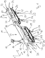
- FIG. 1 a first perspective view of the wing cutting device according to the invention is shown.
- the wing cutting device is for the processing of poultry carcasses 10, of which for reasons of clarity in the figures, only one each is shown, set up and formed.
- the poultry carcasses 10 are conveyed along a conveying path in the transport direction 11 by means of a conveying device 12.
- the conveyor 12 is indicated only schematically in the drawing.
- FIGS. 1 and 2 show the poultry carcass 10 each in a first position, while the poultry carcass 10 in the FIG. 3 is shown in a second position after the poultry carcass 10 has been further conveyed in the transport direction.
- the wing cutting device comprises a first separating device 13 and a second separating device 14.
- the separating devices 13, 14 are designed for the paired separation of wings or wing parts 15 of each one of the poultry carcasses 10.
- the first separator 13 and the second separator 14 are arranged offset along the conveying path such that the paired separation of the wings or the wing parts 15 takes place successively.
- FIG. 1 shows how the poultry carcass 10 during conveying in the transport direction along the conveying path initially passes the first separating device 13.
- the separating device 13 is set up to separate the wing or the wing parts 15 from the right side of the poultry carcass 10. Subsequently, the poultry carcass 10 passes the second separator 14.
- the separator 14 is adapted to separate the wing or wing portions 15 from the left side of the poultry carcass 10.
- the sequence shown of separating the wings or wing parts 15 is purely exemplary. Alternatively, first the left side of the poultry carcass 10 and then the right side of the poultry carcass 10 can be processed with the first separator 13.
- the poultry carcass 10 - as shown in the drawing - conveyed breast side ahead in the transport direction.
- the conveyor 12 comprises carrier elements 16 for conveying and holding poultry carcass 10.
- the conveying device 12 comprises a multiplicity of the carrier elements 16.
- the carrier elements 16 are set up and designed such that the poultry carcasses 10 are mounted transversely to the transport direction 11 or substantially transversely to the transport direction 11.
- the poultry carcass 10 is thus - as in FIG. 4 shown - with its central axis 17 against a conveying axis 18 evasive supported by means of the support elements 16 arranged thereto.
- the poultry carcass 10 is mounted transversely or substantially transversely to the transport direction 11.
- the evasive storage is set up such that the poultry carcass 10 is arranged with its central axis 17 displaceable relative to the conveying axis 18.
- the central axis 17 is a virtual axis passing centrally through the poultry carcass 10 and dividing it into two halves each.
- the conveying axis 18 denotes a centrally through one of the support members 16 vertically extending axis which is perpendicular to the transport direction 11.
- the conveyor axis 18 extends parallel to the Z-axis of in FIG. 4 represented coordinate system.
- the transport direction 11 is directed into the XZ plane.
- the inescapable storage of the poultry carcass 10 is set up such that, with its central axis 17, it can dodge transversely to the transport direction 11, ie at least with a subcomponent in a transverse direction.
- the transverse direction denotes the X direction in the drawing. This leads to the displacement described above between the central axis 17 and the conveying axis 18.
- the conveying axis 18 can be displaced both translationally, ie by displacement in the X direction, as well as by a pivoting movement.
- a combined pivoting / sliding movement leads to an inclination of the central axis 17 relative to the conveying axis 18.
- the alternative storage optionally allows the poultry carcass 10 to be rotated about the Z-axis, ie about the conveying axis 18.
- the conveyor 12 is designed as a hanging conveyor to receive the poultry carcasses 10 by means of the support members 16 to the legs 19 hanging.
- the support elements 16 are more preferably configured in the form of a shoelace and are set up to receive the ankles of the poultry carcass 10.
- the first separating device 13 and the second separating device 14 each comprise guide devices 20.
- Each of the guide devices 20 has a guide gap 21 extending parallel to the transport direction 11.
- the guide devices 20 are set up to hold the wings or the wing parts 15 in each case in one of the guide gaps 21 and to guide them at least substantially parallel to the transport direction 11.
- the guide gaps 21 are formed in the transport direction 11 is tapered. This causes the wings or wing members 15 to be guided to an optimum cutting position.
- the tapered guide gaps 21 the wings or wing parts 15 are aligned in the guide slots 21 so that in particular the joint areas of the wings or the wing parts are accurately positioned in the guide slots 21.
- the guide means 20 each upstream of a threading device 22.
- the threading devices 22 are for threading the wing or the Wing member 15 in the guide gap 21 or in the respective guide gaps 21 set up.
- the threading device 22 - as shown in the drawing - designed as a baffle.
- the threading devices 22 may alternatively also be formed from one or more guide rods or the like.
- the guide means 20 are each a cutting means 23 downstream.
- each of the wing or the wing parts 15 are separated from the poultry carcass 10.
- the cutting means 23 are arranged stationary.
- each of the cutting means 23 comprises two cutting edges 25 forming a cutting gap 24, which are arranged to separate the wing or the wing part 15.
- the guide means 20, the cutting means 23 and the cutting edges 25 are integrally formed.
- a cutting plane formed by the cutting edges 25 and the cutting gap 24 is arranged inclined relative to the horizontal.
- the cutting plane is inclined relative to the X or Z axis.
- the cutting plane is inclined by an angular amount which corresponds to the anatomical conditions of the wing parts 15 of the poultry carcasses 10 to be separated.
- the cutting plane is aligned parallel or substantially parallel to the natural position of the upper wing part 26 of the poultry carcasses 10, so that the middle wing part 27 is separated from the upper wing part 26 by means of the cutting means 23.
- angle specification of the inclination angle of the cutting plane can be separated from the poultry carcass 10 in this way, for example, the wingtips 28 of the poultry carcasses 10 of the middle wing part 27 and / or the upper wing part 26.
- a further preferred embodiment of the invention comprises a number of revolving sliding elements 29.
- the sliding element 29 are each arranged in alignment with one of the carrier elements 16 in the transport direction 11. Further, the sliding elements 29 are arranged to engage respectively with the wing or with the wing members 15. The sliding elements 29 are consequently designed to guide the wings or wing parts 15 to be separated.
- the sliding elements 29 are further configured to engage the respective poultry carcass 10 in a shoulder region 30.
- the sliding elements 29 support in this way both the poultry carcass 10 in the shoulder region 30 and the respective wings or wing parts 15 to be separated.
- the sliding elements 29 are preferably each formed u-shaped profile and each have a Schulter Schlsschiebeteil 31 and a diegel Schlobeteil 32 with an intermediate Sliding part recess 33 include.
- the sliding elements 29 are arranged transversely to the transport direction 11 such that at least one of the guide means 20 are each at least partially disposed in the SchiebeteilausEnglishung 33.
- at least one of the guide device 20 is arranged such that the respective one of the sliding elements 29 at least partially surrounds them.
- the sliding elements 29 are driven by means of at least one - in the drawing only schematically indicated - drive unit 34 for moving the sliding elements 29 in the transport direction 11.
- the drive unit 34 is designed, for example, as a motor-driven, revolving endless conveyor.
- the present invention is not limited solely to the type of drive of the sliding elements 29 described above by way of example only.
- the drive speed of the drive unit 34 is variably set adjustable such that each of the sliding elements 29 is at least temporarily arranged leading or trailing relative to the associated support member 16.
- the drive speed of the drive unit 34 is set up so variable that one of the sliding elements 29 leads or lags relative to the respective associated carrier element 16. This lead or lag is either static, i. during the processing operation set up constant adjustable, or set as a drive speed course assignable, so that the drive speed is varied during the processing operation.
- a casserole 35 is disposed along the conveyor line and adapted to support the poultry carcasses 10 at the neck.
Landscapes
- Life Sciences & Earth Sciences (AREA)
- Engineering & Computer Science (AREA)
- Wood Science & Technology (AREA)
- Zoology (AREA)
- Food Science & Technology (AREA)
- Processing Of Meat And Fish (AREA)
Priority Applications (9)
| Application Number | Priority Date | Filing Date | Title |
|---|---|---|---|
| PL16155538T PL3205213T3 (pl) | 2016-02-12 | 2016-02-12 | Urządzenie do odcinania skrzydeł i sposób oddzielania skrzydeł lub części skrzydeł |
| ES16155538T ES2732731T3 (es) | 2016-02-12 | 2016-02-12 | Dispositivo de corte de alas y procedimiento para separar alas o partes de ala |
| DK16155538.8T DK3205213T3 (da) | 2016-02-12 | 2016-02-12 | Vingeskæreindretning og fremgangsmåde til afskæring af vinger eller vingedele |
| EP16155538.8A EP3205213B1 (de) | 2016-02-12 | 2016-02-12 | Flügelschneidvorrichtung und verfahren zum abtrennen von flügeln oder flügelteilen |
| BR112018009667-9A BR112018009667B1 (pt) | 2016-02-12 | 2017-02-08 | Aparelho de corte de asas e método para separar as asas ou partes das asas das carcaças de aves de corte |
| PCT/EP2017/052727 WO2017137426A1 (de) | 2016-02-12 | 2017-02-08 | Flügelschneidvorrichtung und verfahren zum abtrennen von flügeln oder flügelteilen |
| US15/776,010 US10485243B2 (en) | 2016-02-12 | 2017-02-08 | Wing-cutting apparatus and method for severing wings or wing parts |
| CN201780004021.2A CN108347950B (zh) | 2016-02-12 | 2017-02-08 | 用于分离翅膀或翅膀部分的切翅设备和方法 |
| CA3005148A CA3005148C (en) | 2016-02-12 | 2017-02-08 | Wing-cutting apparatus and method for severing wings or wing parts |
Applications Claiming Priority (1)
| Application Number | Priority Date | Filing Date | Title |
|---|---|---|---|
| EP16155538.8A EP3205213B1 (de) | 2016-02-12 | 2016-02-12 | Flügelschneidvorrichtung und verfahren zum abtrennen von flügeln oder flügelteilen |
Publications (2)
| Publication Number | Publication Date |
|---|---|
| EP3205213A1 EP3205213A1 (de) | 2017-08-16 |
| EP3205213B1 true EP3205213B1 (de) | 2019-04-03 |
Family
ID=55361373
Family Applications (1)
| Application Number | Title | Priority Date | Filing Date |
|---|---|---|---|
| EP16155538.8A Active EP3205213B1 (de) | 2016-02-12 | 2016-02-12 | Flügelschneidvorrichtung und verfahren zum abtrennen von flügeln oder flügelteilen |
Country Status (9)
| Country | Link |
|---|---|
| US (1) | US10485243B2 (zh) |
| EP (1) | EP3205213B1 (zh) |
| CN (1) | CN108347950B (zh) |
| BR (1) | BR112018009667B1 (zh) |
| CA (1) | CA3005148C (zh) |
| DK (1) | DK3205213T3 (zh) |
| ES (1) | ES2732731T3 (zh) |
| PL (1) | PL3205213T3 (zh) |
| WO (1) | WO2017137426A1 (zh) |
Families Citing this family (6)
| Publication number | Priority date | Publication date | Assignee | Title |
|---|---|---|---|---|
| NL2017244B1 (en) * | 2016-07-27 | 2018-02-01 | Meyn Food Processing Tech Bv | Filleting device |
| DK3772969T5 (da) | 2018-06-20 | 2022-04-04 | Linco Food Systems As | Indretning, fremgangsmåde og anordning til afskæring af vingespidserne fra fjerkræslagtekroppe |
| NL2022680B1 (en) | 2019-03-06 | 2020-09-17 | Marel Poultry B V | A poultry transfer mechanism |
| CN111248249B (zh) * | 2020-03-03 | 2021-06-25 | 山东新希望六和集团有限公司 | 一种全自动腰背划线兼掰腿装置 |
| CN112741141B (zh) * | 2021-01-20 | 2022-04-22 | 山东新希望六和集团有限公司 | 一种家禽分割用自动开膛装置 |
| CN114714419B (zh) * | 2022-04-18 | 2023-03-17 | 青岛锐智智能装备科技有限公司 | 一种鸡中翅切割装置及其切割方法 |
Family Cites Families (18)
| Publication number | Priority date | Publication date | Assignee | Title |
|---|---|---|---|---|
| US4715092A (en) * | 1985-01-04 | 1987-12-29 | Automatic Packaging Systems, Inc. | Apparatus and method for cutting slaughtered poultry into separate pieces |
| US4669148A (en) * | 1985-01-23 | 1987-06-02 | Simon-Johnson, Inc. | Machine for cutting up poultry into a number of pieces |
| DE3735849A1 (de) * | 1987-10-23 | 1989-05-03 | Nordischer Maschinenbau | Verfahren zum entfernen der fluegel von gefluegelkoerpern und einrichtung zur durchfuehrung des verfahrens |
| DK166598B1 (da) | 1990-10-30 | 1993-06-21 | Lindholst & Co As | Fremgangsmaade og apparat til afskaering af vingerne fra kroppen af slagtet fjerkrae. |
| US5188560A (en) * | 1992-01-22 | 1993-02-23 | Hazenbroek Jacobus E | Wing tip cutter |
| NL9401198A (nl) * | 1994-07-21 | 1996-03-01 | Stork Pmt | Werkwijze en inrichting voor het fileren van de romp van geslacht gevogelte. |
| US5429549A (en) * | 1994-10-05 | 1995-07-04 | Systemate Holland, B.V. | Sequential wing remover |
| DE19500014A1 (de) * | 1995-01-03 | 1996-07-04 | Nordischer Maschinenbau | Einrichtung zum Zerlegen der Flügel von Geflügelkörper |
| EP1266574B1 (en) * | 1996-06-21 | 2008-01-16 | Mayekawa Manufacturing Co., Ltd. | System of automatically loading parts of poultry carcasses to a plurality of apparatus |
| EP0784932B1 (en) * | 1996-08-12 | 2002-06-26 | Systemate Holland B.V. | Wing Remover |
| GB9712015D0 (en) * | 1997-06-11 | 1997-08-06 | Filar Limited | Procedure and apparatus for deboning poultry |
| US5954574A (en) * | 1997-08-12 | 1999-09-21 | Verrijp; Bastiaan | Wing remover |
| US6322438B1 (en) * | 1999-07-15 | 2001-11-27 | Systemate Group, B.V. | Poultry leg and thigh processor |
| US6638156B2 (en) * | 2001-03-14 | 2003-10-28 | Tyson Foods, Inc. | Secondary halving apparatus for poultry |
| US7335095B2 (en) * | 2004-03-31 | 2008-02-26 | Mayekawa Mfg. Co., Ltd. | Apparatus and method for separating wings from breast meat of poultry |
| EP1956919B1 (en) * | 2005-12-09 | 2015-10-21 | Marel Stork Poultry Processing B.V. | Method and device for processing a carcass part of slaughtered poultry |
| US7341505B1 (en) * | 2006-11-29 | 2008-03-11 | Remington Holdings Llc | Bird wing cutting machine |
| NL2006312C2 (en) * | 2011-02-28 | 2012-08-29 | Meyn Food Proc Technology Bv | Method and apparatus for processing a wing of a poultry carcass while the wing is attached to said poultry carcass. |
-
2016
- 2016-02-12 PL PL16155538T patent/PL3205213T3/pl unknown
- 2016-02-12 EP EP16155538.8A patent/EP3205213B1/de active Active
- 2016-02-12 DK DK16155538.8T patent/DK3205213T3/da active
- 2016-02-12 ES ES16155538T patent/ES2732731T3/es active Active
-
2017
- 2017-02-08 US US15/776,010 patent/US10485243B2/en active Active
- 2017-02-08 CN CN201780004021.2A patent/CN108347950B/zh active Active
- 2017-02-08 WO PCT/EP2017/052727 patent/WO2017137426A1/de active Application Filing
- 2017-02-08 CA CA3005148A patent/CA3005148C/en active Active
- 2017-02-08 BR BR112018009667-9A patent/BR112018009667B1/pt active IP Right Grant
Non-Patent Citations (1)
| Title |
|---|
| None * |
Also Published As
| Publication number | Publication date |
|---|---|
| US20180325130A1 (en) | 2018-11-15 |
| CN108347950A (zh) | 2018-07-31 |
| CN108347950B (zh) | 2020-11-10 |
| CA3005148A1 (en) | 2017-08-17 |
| EP3205213A1 (de) | 2017-08-16 |
| WO2017137426A1 (de) | 2017-08-17 |
| ES2732731T3 (es) | 2019-11-25 |
| BR112018009667B1 (pt) | 2023-04-25 |
| DK3205213T3 (da) | 2019-07-01 |
| CA3005148C (en) | 2020-05-12 |
| US10485243B2 (en) | 2019-11-26 |
| BR112018009667A2 (pt) | 2018-12-18 |
| PL3205213T3 (pl) | 2019-09-30 |
Similar Documents
| Publication | Publication Date | Title |
|---|---|---|
| EP3205213B1 (de) | Flügelschneidvorrichtung und verfahren zum abtrennen von flügeln oder flügelteilen | |
| EP2159173B1 (de) | Transportvorrichtung und Verfahren zum geordneten Transport von Artikeln | |
| EP3172020B1 (de) | Aufschneidevorrichtung | |
| EP2671829B1 (de) | Spreizeinrichtung | |
| EP3378616B1 (de) | Verarbeitung von lebensmittelprodukten | |
| EP3372538A1 (de) | Transportabschnitt, verfahren zum einstellen und/oder verstellen mindestens einer transportbahn innerhalb eines transportabschnitts und verpackungsanlage | |
| EP2420364B1 (de) | Portionskomplettierung beim mehrspurigen Aufschneiden | |
| EP3069836A1 (de) | Überlappungsvorrichtung | |
| EP3095566B1 (de) | Zuführvorrichtung | |
| EP2420344A1 (de) | Verfahren und Vorrichtung zum Herstellen eines Konturschnitts in einem Blechband | |
| WO2016202760A1 (de) | Aufschneidevorrichtung | |
| EP2543452A1 (de) | Biegevorrichtung für stabförmige Werkstücke | |
| WO2003028963A1 (de) | Vorrichtung zum aufschneiden von lebensmittelprodukten | |
| EP4335296A2 (de) | Anordnung und verfahren zur geflügelförderung | |
| EP3785543B1 (de) | Schneidvorrichtung | |
| EP2478782A2 (de) | Fördervorrichtung für stabförmige Produkte der Tabak verarbeitenden Industrie | |
| EP2566744B1 (de) | Verfahren zum betrieb einer aufschneidmaschine mit mehrspuriger zufuhr | |
| EP2522472B1 (de) | Perforationseinheit einer Verpackungsmaschine | |
| DE102018124212A1 (de) | Förderstrecke für einen Transport einer Vielzahl von Artikeln und Verfahren zum Anpassen und/oder Betreiben einer Förderstrecke | |
| EP3268174B1 (de) | Verfahren und vorrichtung zur vermeidung von leerpackungen | |
| EP4001187A1 (de) | Verfahren zum quer-positionieren eines zu transportierenden artikels | |
| EP2982622B1 (de) | Vorrichtung zum verteilen eines stroms von produkten | |
| EP4032669A1 (de) | Mehrspurige aufschneide-maschine mit unabhängig ansteuerbaren greifern | |
| DE102019123999A1 (de) | Schneidvorrichtung | |
| DE202016105590U1 (de) | Vorrichtung zum Sortieren mit Stückgütern mit Dosiereinrichtung |
Legal Events
| Date | Code | Title | Description |
|---|---|---|---|
| PUAI | Public reference made under article 153(3) epc to a published international application that has entered the european phase |
Free format text: ORIGINAL CODE: 0009012 |
|
| STAA | Information on the status of an ep patent application or granted ep patent |
Free format text: STATUS: THE APPLICATION HAS BEEN PUBLISHED |
|
| AK | Designated contracting states |
Kind code of ref document: A1 Designated state(s): AL AT BE BG CH CY CZ DE DK EE ES FI FR GB GR HR HU IE IS IT LI LT LU LV MC MK MT NL NO PL PT RO RS SE SI SK SM TR |
|
| AX | Request for extension of the european patent |
Extension state: BA ME |
|
| RAP1 | Party data changed (applicant data changed or rights of an application transferred) |
Owner name: LINCO FOOD SYSTEMS A/S |
|
| STAA | Information on the status of an ep patent application or granted ep patent |
Free format text: STATUS: REQUEST FOR EXAMINATION WAS MADE |
|
| 17P | Request for examination filed |
Effective date: 20171201 |
|
| RBV | Designated contracting states (corrected) |
Designated state(s): AL AT BE BG CH CY CZ DE DK EE ES FI FR GB GR HR HU IE IS IT LI LT LU LV MC MK MT NL NO PL PT RO RS SE SI SK SM TR |
|
| GRAP | Despatch of communication of intention to grant a patent |
Free format text: ORIGINAL CODE: EPIDOSNIGR1 |
|
| STAA | Information on the status of an ep patent application or granted ep patent |
Free format text: STATUS: GRANT OF PATENT IS INTENDED |
|
| INTG | Intention to grant announced |
Effective date: 20181004 |
|
| GRAJ | Information related to disapproval of communication of intention to grant by the applicant or resumption of examination proceedings by the epo deleted |
Free format text: ORIGINAL CODE: EPIDOSDIGR1 |
|
| STAA | Information on the status of an ep patent application or granted ep patent |
Free format text: STATUS: REQUEST FOR EXAMINATION WAS MADE |
|
| GRAR | Information related to intention to grant a patent recorded |
Free format text: ORIGINAL CODE: EPIDOSNIGR71 |
|
| GRAS | Grant fee paid |
Free format text: ORIGINAL CODE: EPIDOSNIGR3 |
|
| STAA | Information on the status of an ep patent application or granted ep patent |
Free format text: STATUS: GRANT OF PATENT IS INTENDED |
|
| GRAA | (expected) grant |
Free format text: ORIGINAL CODE: 0009210 |
|
| STAA | Information on the status of an ep patent application or granted ep patent |
Free format text: STATUS: THE PATENT HAS BEEN GRANTED |
|
| INTC | Intention to grant announced (deleted) | ||
| RIN1 | Information on inventor provided before grant (corrected) |
Inventor name: VEEN, TIM ANDRIES Inventor name: GERRITSEN, JOHANNES CORNELIS Inventor name: POLMAN, RUDI THEODORUS MARIA |
|
| INTG | Intention to grant announced |
Effective date: 20190208 |
|
| AK | Designated contracting states |
Kind code of ref document: B1 Designated state(s): AL AT BE BG CH CY CZ DE DK EE ES FI FR GB GR HR HU IE IS IT LI LT LU LV MC MK MT NL NO PL PT RO RS SE SI SK SM TR |
|
| REG | Reference to a national code |
Ref country code: GB Ref legal event code: FG4D Free format text: NOT ENGLISH |
|
| REG | Reference to a national code |
Ref country code: CH Ref legal event code: EP Ref country code: AT Ref legal event code: REF Ref document number: 1114621 Country of ref document: AT Kind code of ref document: T Effective date: 20190415 |
|
| REG | Reference to a national code |
Ref country code: DE Ref legal event code: R096 Ref document number: 502016003955 Country of ref document: DE |
|
| REG | Reference to a national code |
Ref country code: IE Ref legal event code: FG4D Free format text: LANGUAGE OF EP DOCUMENT: GERMAN |
|
| REG | Reference to a national code |
Ref country code: DK Ref legal event code: T3 Effective date: 20190628 |
|
| REG | Reference to a national code |
Ref country code: NL Ref legal event code: FP |
|
| REG | Reference to a national code |
Ref country code: LT Ref legal event code: MG4D |
|
| PG25 | Lapsed in a contracting state [announced via postgrant information from national office to epo] |
Ref country code: CZ Free format text: LAPSE BECAUSE OF FAILURE TO SUBMIT A TRANSLATION OF THE DESCRIPTION OR TO PAY THE FEE WITHIN THE PRESCRIBED TIME-LIMIT Effective date: 20190403 Ref country code: AL Free format text: LAPSE BECAUSE OF FAILURE TO SUBMIT A TRANSLATION OF THE DESCRIPTION OR TO PAY THE FEE WITHIN THE PRESCRIBED TIME-LIMIT Effective date: 20190403 Ref country code: PT Free format text: LAPSE BECAUSE OF FAILURE TO SUBMIT A TRANSLATION OF THE DESCRIPTION OR TO PAY THE FEE WITHIN THE PRESCRIBED TIME-LIMIT Effective date: 20190803 Ref country code: LT Free format text: LAPSE BECAUSE OF FAILURE TO SUBMIT A TRANSLATION OF THE DESCRIPTION OR TO PAY THE FEE WITHIN THE PRESCRIBED TIME-LIMIT Effective date: 20190403 Ref country code: HR Free format text: LAPSE BECAUSE OF FAILURE TO SUBMIT A TRANSLATION OF THE DESCRIPTION OR TO PAY THE FEE WITHIN THE PRESCRIBED TIME-LIMIT Effective date: 20190403 Ref country code: SE Free format text: LAPSE BECAUSE OF FAILURE TO SUBMIT A TRANSLATION OF THE DESCRIPTION OR TO PAY THE FEE WITHIN THE PRESCRIBED TIME-LIMIT Effective date: 20190403 Ref country code: NO Free format text: LAPSE BECAUSE OF FAILURE TO SUBMIT A TRANSLATION OF THE DESCRIPTION OR TO PAY THE FEE WITHIN THE PRESCRIBED TIME-LIMIT Effective date: 20190703 Ref country code: FI Free format text: LAPSE BECAUSE OF FAILURE TO SUBMIT A TRANSLATION OF THE DESCRIPTION OR TO PAY THE FEE WITHIN THE PRESCRIBED TIME-LIMIT Effective date: 20190403 |
|
| REG | Reference to a national code |
Ref country code: ES Ref legal event code: FG2A Ref document number: 2732731 Country of ref document: ES Kind code of ref document: T3 Effective date: 20191125 |
|
| PG25 | Lapsed in a contracting state [announced via postgrant information from national office to epo] |
Ref country code: LV Free format text: LAPSE BECAUSE OF FAILURE TO SUBMIT A TRANSLATION OF THE DESCRIPTION OR TO PAY THE FEE WITHIN THE PRESCRIBED TIME-LIMIT Effective date: 20190403 Ref country code: RS Free format text: LAPSE BECAUSE OF FAILURE TO SUBMIT A TRANSLATION OF THE DESCRIPTION OR TO PAY THE FEE WITHIN THE PRESCRIBED TIME-LIMIT Effective date: 20190403 Ref country code: GR Free format text: LAPSE BECAUSE OF FAILURE TO SUBMIT A TRANSLATION OF THE DESCRIPTION OR TO PAY THE FEE WITHIN THE PRESCRIBED TIME-LIMIT Effective date: 20190704 Ref country code: BG Free format text: LAPSE BECAUSE OF FAILURE TO SUBMIT A TRANSLATION OF THE DESCRIPTION OR TO PAY THE FEE WITHIN THE PRESCRIBED TIME-LIMIT Effective date: 20190703 |
|
| REG | Reference to a national code |
Ref country code: DE Ref legal event code: R097 Ref document number: 502016003955 Country of ref document: DE |
|
| PG25 | Lapsed in a contracting state [announced via postgrant information from national office to epo] |
Ref country code: SK Free format text: LAPSE BECAUSE OF FAILURE TO SUBMIT A TRANSLATION OF THE DESCRIPTION OR TO PAY THE FEE WITHIN THE PRESCRIBED TIME-LIMIT Effective date: 20190403 Ref country code: RO Free format text: LAPSE BECAUSE OF FAILURE TO SUBMIT A TRANSLATION OF THE DESCRIPTION OR TO PAY THE FEE WITHIN THE PRESCRIBED TIME-LIMIT Effective date: 20190403 Ref country code: EE Free format text: LAPSE BECAUSE OF FAILURE TO SUBMIT A TRANSLATION OF THE DESCRIPTION OR TO PAY THE FEE WITHIN THE PRESCRIBED TIME-LIMIT Effective date: 20190403 |
|
| PLBE | No opposition filed within time limit |
Free format text: ORIGINAL CODE: 0009261 |
|
| STAA | Information on the status of an ep patent application or granted ep patent |
Free format text: STATUS: NO OPPOSITION FILED WITHIN TIME LIMIT |
|
| PG25 | Lapsed in a contracting state [announced via postgrant information from national office to epo] |
Ref country code: SM Free format text: LAPSE BECAUSE OF FAILURE TO SUBMIT A TRANSLATION OF THE DESCRIPTION OR TO PAY THE FEE WITHIN THE PRESCRIBED TIME-LIMIT Effective date: 20190403 Ref country code: IT Free format text: LAPSE BECAUSE OF FAILURE TO SUBMIT A TRANSLATION OF THE DESCRIPTION OR TO PAY THE FEE WITHIN THE PRESCRIBED TIME-LIMIT Effective date: 20190403 |
|
| 26N | No opposition filed |
Effective date: 20200106 |
|
| PG25 | Lapsed in a contracting state [announced via postgrant information from national office to epo] |
Ref country code: TR Free format text: LAPSE BECAUSE OF FAILURE TO SUBMIT A TRANSLATION OF THE DESCRIPTION OR TO PAY THE FEE WITHIN THE PRESCRIBED TIME-LIMIT Effective date: 20190403 |
|
| PG25 | Lapsed in a contracting state [announced via postgrant information from national office to epo] |
Ref country code: SI Free format text: LAPSE BECAUSE OF FAILURE TO SUBMIT A TRANSLATION OF THE DESCRIPTION OR TO PAY THE FEE WITHIN THE PRESCRIBED TIME-LIMIT Effective date: 20190403 |
|
| REG | Reference to a national code |
Ref country code: CH Ref legal event code: PL |
|
| REG | Reference to a national code |
Ref country code: BE Ref legal event code: MM Effective date: 20200229 |
|
| PG25 | Lapsed in a contracting state [announced via postgrant information from national office to epo] |
Ref country code: LU Free format text: LAPSE BECAUSE OF NON-PAYMENT OF DUE FEES Effective date: 20200212 Ref country code: MC Free format text: LAPSE BECAUSE OF FAILURE TO SUBMIT A TRANSLATION OF THE DESCRIPTION OR TO PAY THE FEE WITHIN THE PRESCRIBED TIME-LIMIT Effective date: 20190403 |
|
| PG25 | Lapsed in a contracting state [announced via postgrant information from national office to epo] |
Ref country code: LI Free format text: LAPSE BECAUSE OF NON-PAYMENT OF DUE FEES Effective date: 20200229 Ref country code: CH Free format text: LAPSE BECAUSE OF NON-PAYMENT OF DUE FEES Effective date: 20200229 |
|
| PG25 | Lapsed in a contracting state [announced via postgrant information from national office to epo] |
Ref country code: IE Free format text: LAPSE BECAUSE OF NON-PAYMENT OF DUE FEES Effective date: 20200212 |
|
| PG25 | Lapsed in a contracting state [announced via postgrant information from national office to epo] |
Ref country code: BE Free format text: LAPSE BECAUSE OF NON-PAYMENT OF DUE FEES Effective date: 20200229 |
|
| REG | Reference to a national code |
Ref country code: AT Ref legal event code: MM01 Ref document number: 1114621 Country of ref document: AT Kind code of ref document: T Effective date: 20210212 |
|
| PG25 | Lapsed in a contracting state [announced via postgrant information from national office to epo] |
Ref country code: AT Free format text: LAPSE BECAUSE OF NON-PAYMENT OF DUE FEES Effective date: 20210212 |
|
| REG | Reference to a national code |
Ref country code: DE Ref legal event code: R081 Ref document number: 502016003955 Country of ref document: DE Owner name: BAADER FOOD SYSTEMS DENMARK A/S, DK Free format text: FORMER OWNER: LINCO FOOD SYSTEMS A/S, TRIGE, DK |
|
| PG25 | Lapsed in a contracting state [announced via postgrant information from national office to epo] |
Ref country code: MT Free format text: LAPSE BECAUSE OF FAILURE TO SUBMIT A TRANSLATION OF THE DESCRIPTION OR TO PAY THE FEE WITHIN THE PRESCRIBED TIME-LIMIT Effective date: 20190403 Ref country code: CY Free format text: LAPSE BECAUSE OF FAILURE TO SUBMIT A TRANSLATION OF THE DESCRIPTION OR TO PAY THE FEE WITHIN THE PRESCRIBED TIME-LIMIT Effective date: 20190403 |
|
| PG25 | Lapsed in a contracting state [announced via postgrant information from national office to epo] |
Ref country code: MK Free format text: LAPSE BECAUSE OF FAILURE TO SUBMIT A TRANSLATION OF THE DESCRIPTION OR TO PAY THE FEE WITHIN THE PRESCRIBED TIME-LIMIT Effective date: 20190403 |
|
| REG | Reference to a national code |
Ref country code: NL Ref legal event code: HC Owner name: BAADER FOOD SYSTEMS DENMARK A/S; DK Free format text: DETAILS ASSIGNMENT: CHANGE OF OWNER(S), CHANGE OF OWNER(S) NAME; FORMER OWNER NAME: LINCO FOOD SYSTEMS A/S Effective date: 20230308 |
|
| P01 | Opt-out of the competence of the unified patent court (upc) registered |
Effective date: 20230516 |
|
| PGFP | Annual fee paid to national office [announced via postgrant information from national office to epo] |
Ref country code: IS Payment date: 20240117 Year of fee payment: 9 |
|
| PGFP | Annual fee paid to national office [announced via postgrant information from national office to epo] |
Ref country code: NL Payment date: 20240220 Year of fee payment: 9 Ref country code: ES Payment date: 20240319 Year of fee payment: 9 |
|
| PGFP | Annual fee paid to national office [announced via postgrant information from national office to epo] |
Ref country code: DE Payment date: 20240216 Year of fee payment: 9 Ref country code: GB Payment date: 20240222 Year of fee payment: 9 |
|
| PGFP | Annual fee paid to national office [announced via postgrant information from national office to epo] |
Ref country code: PL Payment date: 20240105 Year of fee payment: 9 Ref country code: FR Payment date: 20240221 Year of fee payment: 9 Ref country code: DK Payment date: 20240221 Year of fee payment: 9 |