EP3204105B1 - Implantierbare elektrodenanordnung - Google Patents
Implantierbare elektrodenanordnung Download PDFInfo
- Publication number
- EP3204105B1 EP3204105B1 EP15774937.5A EP15774937A EP3204105B1 EP 3204105 B1 EP3204105 B1 EP 3204105B1 EP 15774937 A EP15774937 A EP 15774937A EP 3204105 B1 EP3204105 B1 EP 3204105B1
- Authority
- EP
- European Patent Office
- Prior art keywords
- electrode
- carrier substrate
- electrode device
- strips
- extension
- Prior art date
- Legal status (The legal status is an assumption and is not a legal conclusion. Google has not performed a legal analysis and makes no representation as to the accuracy of the status listed.)
- Active
Links
Images

Classifications
-
- A—HUMAN NECESSITIES
- A61—MEDICAL OR VETERINARY SCIENCE; HYGIENE
- A61N—ELECTROTHERAPY; MAGNETOTHERAPY; RADIATION THERAPY; ULTRASOUND THERAPY
- A61N1/00—Electrotherapy; Circuits therefor
- A61N1/02—Details
- A61N1/04—Electrodes
- A61N1/05—Electrodes for implantation or insertion into the body, e.g. heart electrode
- A61N1/0551—Spinal or peripheral nerve electrodes
- A61N1/0556—Cuff electrodes
-
- A—HUMAN NECESSITIES
- A61—MEDICAL OR VETERINARY SCIENCE; HYGIENE
- A61B—DIAGNOSIS; SURGERY; IDENTIFICATION
- A61B5/00—Measuring for diagnostic purposes; Identification of persons
- A61B5/24—Detecting, measuring or recording bioelectric or biomagnetic signals of the body or parts thereof
-
- A—HUMAN NECESSITIES
- A61—MEDICAL OR VETERINARY SCIENCE; HYGIENE
- A61B—DIAGNOSIS; SURGERY; IDENTIFICATION
- A61B5/00—Measuring for diagnostic purposes; Identification of persons
- A61B5/24—Detecting, measuring or recording bioelectric or biomagnetic signals of the body or parts thereof
- A61B5/316—Modalities, i.e. specific diagnostic methods
- A61B5/388—Nerve conduction study, e.g. detecting action potential of peripheral nerves
-
- A—HUMAN NECESSITIES
- A61—MEDICAL OR VETERINARY SCIENCE; HYGIENE
- A61N—ELECTROTHERAPY; MAGNETOTHERAPY; RADIATION THERAPY; ULTRASOUND THERAPY
- A61N1/00—Electrotherapy; Circuits therefor
- A61N1/18—Applying electric currents by contact electrodes
- A61N1/32—Applying electric currents by contact electrodes alternating or intermittent currents
- A61N1/36—Applying electric currents by contact electrodes alternating or intermittent currents for stimulation
- A61N1/3605—Implantable neurostimulators for stimulating central or peripheral nerve system
- A61N1/3606—Implantable neurostimulators for stimulating central or peripheral nerve system adapted for a particular treatment
- A61N1/36114—Cardiac control, e.g. by vagal stimulation
- A61N1/36117—Cardiac control, e.g. by vagal stimulation for treating hypertension
-
- A—HUMAN NECESSITIES
- A61—MEDICAL OR VETERINARY SCIENCE; HYGIENE
- A61N—ELECTROTHERAPY; MAGNETOTHERAPY; RADIATION THERAPY; ULTRASOUND THERAPY
- A61N1/00—Electrotherapy; Circuits therefor
- A61N1/18—Applying electric currents by contact electrodes
- A61N1/32—Applying electric currents by contact electrodes alternating or intermittent currents
- A61N1/36—Applying electric currents by contact electrodes alternating or intermittent currents for stimulation
- A61N1/3605—Implantable neurostimulators for stimulating central or peripheral nerve system
- A61N1/36128—Control systems
-
- A—HUMAN NECESSITIES
- A61—MEDICAL OR VETERINARY SCIENCE; HYGIENE
- A61B—DIAGNOSIS; SURGERY; IDENTIFICATION
- A61B2562/00—Details of sensors; Constructional details of sensor housings or probes; Accessories for sensors
- A61B2562/06—Arrangements of multiple sensors of different types
- A61B2562/066—Arrangements of multiple sensors of different types in a matrix array
-
- A—HUMAN NECESSITIES
- A61—MEDICAL OR VETERINARY SCIENCE; HYGIENE
- A61B—DIAGNOSIS; SURGERY; IDENTIFICATION
- A61B2562/00—Details of sensors; Constructional details of sensor housings or probes; Accessories for sensors
- A61B2562/16—Details of sensor housings or probes; Details of structural supports for sensors
- A61B2562/164—Details of sensor housings or probes; Details of structural supports for sensors the sensor is mounted in or on a conformable substrate or carrier
Definitions
- the invention relates to an implantable electrode arrangement for the location-selective detection of neuronal electrical signals which propagate along at least one nerve fiber contained in a nerve fiber bundle and for the selective electrical stimulation of the at least one selected nerve fiber, with a biocompatible carrier substrate having at least one carrier substrate region around the nerve fiber bundle is cuff-like applied and a in the implanted state the nerve fiber bundle facing oriented, straight cylindrical carrier substrate surface having an axial and a circumferentially oriented extent and to which a first electrode assembly is mounted.
- the first electrode arrangement comprises, in axial sequence, at least three first electrode structures spaced apart from one another, each having at least two first electrode surfaces distributed in the circumferential direction, and at least two axially relative to one another spaced, circumferentially extending and each receiving a ring shape, first electrode strips which enclose the at least three electrode structures axially on both sides.
- the first electrode arrangement can be connected to a signal detector and generator, ie the electrode arrangement is connected via a separable electrical interface, for example in the form of a plug unit to the signal detector and generator, or directly, ie inseparably connected.
- vagus nerve stimulation is based on the experience of many years of established and established neuromodulatory therapy of severe forms of epilepsy, in which the vagus nerve is electrically stimulated with the help of an implanted electrode assembly to at least their extent in terms of strength in developing epileptic seizures and to mitigate their duration, see F. Sidiqui, et al., "Cumulative Effect of Vagic Nerve Stimulators on Intractable Seizures Observed over a Period of 3 Years," Epilepsy and Behavior, 18 (3), pp. 299-302, 2010 such as T. Stieglitz, "Neuroprosthetics and Neuromodulation - Research Approaches and Clinical Practice in Therapy and Rehabilitation", Bundes Rheinsblatt - Health Research - Health Protection, 53 (8), pp. 783 - 790, 2010 ,
- the blood pressure-relevant fibers first have to be localized in order to then selectively selectively stimulate them electrically.
- the vagus nerve As much as possible by the implantation of the application of an electrode assembly and not to irritate the epineurium of the vagus nerve as possible, is in the cited article by Dennis T. T. Plachta et al. proposed the use of a so-called. Cuff electrode which is extraneurally attachable to the vagus nerve. This has the advantage of a relatively easy positioning of the cuff electrode along the vagus nerve and also allows a slightly invasive and therefore gentle and easy to perform surgical intervention on the patient.
- Baroreflex For the natural blood pressure control is the Baroreflex, which represents a homeostatic, self-regulating mechanism and at a increased blood pressure reflexively activates different effectors. Among other things, the heart rate is lowered, but also the arterial vessels are widened in order to lower the blood pressure. In the case of low blood pressure, the baroreflex is suppressed, increasing heart rate and narrowing blood vessels to increase blood pressure.
- the sensory inputs for the baroreflex represent so-called baroreceptors, which are located, inter alia, in the walls of the aortic arch. From there, the blood pressure information draw monosynaptically along the blood pressure-relevant nerve fibers, hereinafter referred to as baroreceptive fibers, in the brainstem.
- FIG. 2a shows the known sleeve electrode CE in a planar plan view in a planar unfolded state.
- FIG. 2b Fig. 11 shows the cuff electrode CE in the implanted state, in which regions B1, B2 of the cuff electrode CE are folded on each other for a space-saving shape, and moreover, a carrier substrate region 1B of the cuff electrode CE provided with an electrode assembly 2 cuffedly comprises a portion of a nerve fiber bundle NFB.
- the cuff electrode CE consists of a flexible, biocompatible carrier substrate 1, which in the realized embodiment is an approximately 11 ⁇ m thick polyimide film, on whose plane of the drawing in FIG FIG. 2a facing carrier substrate top for purposes of spatially resolved detection of neuronal electrical signals as well as for the selective electrical stimulation of individual in Nerve fiber bundle NFB extending nerve fibers NF one composed of a plurality of individual electrodes electrode assembly 2 is applied.
- the individual electrodes of the electrode assembly 2 come into direct surface contact with the epineurium E of the nerve fiber bundle NFB, since the carrier substrate 1 in the carrier substrate area 1B by means of corresponding impression of a mechanical foil prestressing self-curling to form a straight cylindrical carrier substrate surface 1 'facing the nerve fiber bundle NFB, as in FIG. 2b is apparent.
- the individual electrodes of the electrode assembly 2 take on an annular space shape bent in the circumferential direction U around the nerve fiber bundle NFB.
- Both for location-selective detection of neuronal electrical signals as well as for the selective electrical stimulation of at least one nerve fiber NF serve three axially equally spaced from each other arranged first electrode structures 3, in the circumferential direction U at least two, in the illustrated embodiment according to FIG. 2a, b each eight first electrode surfaces 4 include.
- the respective eight first electrode surfaces 4 belonging to a first electrode structure 3 are equally distributed in the circumferential direction U, ie arranged at 45 ° angular intervals. This allows an eightfold, in the circumferential direction divided site selectivity for the location-selective detection of neuronal electrical signals from the nerve fiber bundle to be examined NFB.
- the first electrode strips 5 which are arranged axially on both sides next to the three first electrode structures 3 and which completely surround the nerve fiber bundle NFB, serve as ground potential in the case of the locally selective detection of neuronal electrical signals; If, on the other hand, it is intended to electrically stimulate selectively selected nerve fibers NF within the nerve fiber bundle NFB, these first electrode strips 5 each serve as anode or as opposite polarity.
- first electrode structures 3 and first each taking a ring shape accepting electrode strips 5, all of which at the in FIG.
- Reference surfaces 12 located on the carrier substrate 1 are located on the back side of the carrier substrate 1, which serve for detecting the intracorporeal electrical background mass signal or noise level, which is used as a basis for the signal evaluation.
- the electrode assembly which can be implanted as a sleeve electrode CE can be connected via the electrical connection structures V to a hermetically sealed signal detector and generator 6, which is likewise designed as an implant.
- baroreceptive signals blood pressure correlated, neuronal electrical time signals, hereinafter referred to as baroreceptive signals, can be detected moreover, with respect to their circumferentially dependent signal levels to locate the baroreceptive nerve fibers.
- the stimulation was tripolar in each case with that electrode surface 4 or those electrode surfaces 4 of the centrally arranged first electrode structure 3 of the tripole arrangement, was detected by the detection of the respective largest signal level among the barorezeptiven signals.
- bradycardia pulse reduction below 60 beats per Minute
- bradypnea reduction in breathing under 20 breaths per minute
- electrical stimulation signals with a stimulation frequency in each case between 30 to 50 Hz, a stimulation time of 0.1 to 0.5 msec and a stimulation amplitude of 0.4 to 1.5 mA to each selected electrode surfaces 4 of centrally applied electrode structure applied.
- the electrical stimulation along the baroreceptive nerve fibers was isotropic, d. H. without specifying a fixed signal propagation direction, so that the electrical stimulation signals could spread along both afferent and efferent nerve fibers. The latter can exert a direct, uncontrolled influence on cardiac activity, which can lead to undesirable side effects, especially in larger animals compared to rats.
- the invention has for its object an implantable electrode assembly of the type described above for the location-selective detection of neuronal electrical signals that extend along at least one contained in a nerve fiber bundle nerve fibers, as well as for selective electrical stimulation of at least one nerve fiber with the features of the preamble of claim 1 , so that provision should be made to exclude possible side effects as possible due to uncontrolled signal propagation effects of longitudinally in baroreceptive nerve fibers selectively coupled, electrical stimulation signals as completely as possible. In particular, provision should be made to prevent propagation of electrical stimulation signals along efferent nerve fibers without exerting a significantly lasting influence on non-baroceptive, afferent and efferent nerve fibers within the nerve fiber bundle.
- the implantable electrode arrangement according to the invention in accordance with the features of the preamble of claim 1 is characterized in that at least one second electrode arrangement is arranged axially next to the first electrode arrangement in axial sequence on the straight-cylindrical carrier substrate surface facing the nerve fiber bundle, which has at least two axially spaced-apart, circumferentially extending ones and in each case a ring shape-accepting second electrode strips and axially between the at least two second electrode strips at least one each at least two circumferentially equally distributed second electrode surfaces comprising second electrode structure, wherein the second electrode assembly is at least connected to the signal generator or another signal generator.
- the second electrode arrangement likewise applied to the same, integrally connected carrier substrate on the same carrier substrate surface as the first electrode arrangement is spatially fixed to the first electrode arrangement, in particular to the first electrode surfaces of the at least three first electrode structures, with the aid of which baroreceptive nerve fibers within the Nerve fiber bundles are detected site selective and beyond selectively electrically stimulated.
- the second electrode assembly may be longitudinally efferent for purposes of selectively inhibiting the baroreceptive nerve fibers to suppress transmission of electrical stimulation signals. ie use to the heart of leading nerve fibers. At least two, preferably four or more, second electrode surfaces of at least one second electrode structure are used for this purpose.
- first electrode surfaces of one of the at least three first electrode structures are equally distributed in the circumferential direction of the carrier layer surface facing the nerve fiber bundle.
- at least one of the second electrode surfaces of the second electrode structure is electrically activated, thereby providing selective, timed, selective inhibition of the respective efferent nerve fiber.
- an electric polarization field enters the nerve fiber bundle from the respectively at least one activated, second electrode surface and interacts primarily with the nerve fiber to be inhibited.
- second electrode strips are provided axially on both sides of the second electrode structure and represent ring electrodes completely enclosing the nerve fiber bundle in the implanted state of the cuff electrode.
- the implantable electrode arrangement designed in accordance with the invention is to be applied to the nerve fiber bundle such that the second electrode arrangement provided according to the invention faces the heart or the baroreceptive receptors, i. caudally, and the first electrode arrangement, which makes selective detection of neuronal electrical signals, as well as the electrical stimulation of localized nerve fibers, to the brain, i. rostral, oriented along the nerve fiber bundle.
- the inhibition can be realized either by means of a so-called anodal block or by application of sinusoidal signals of frequencies in the kilohertz range.
- the anodal block at least one of the second electrode surfaces is anodically polarized, thereby producing a voltage potential prevailing at the location of the efferent nerve fiber, by which an activating stimulation of the corresponding nerve fiber is suppressed.
- an inhibition can be achieved by means of a high-frequency signal application in which a high-frequency electrical inhibition signal is applied to at least one selected second electrode surface, whereby the electrical signal transmission mechanisms come to a halt briefly along the efferent nerve fibers.
- the solution provided according to the second electrode arrangement acts due to their spatial axial limitation, which is given by the axial distance of the two second electrode strips, despite their proximity to the first electrode structure, after all, the implantable electrode assembly should not exceed an axial length of 4 cm, axially spaced bounded along the efferent nerve fibers to be inhibited, so that the first electrode arrangement arranged on the brain side along the nerve fiber bundle can couple in the respectively localized afferent nerve fibers to the brain leading electrical stimulation signals uninfluenced by the inhibition mechanism. In this way, any side effects due to possible direct stimulations towards the heart, i. efferent nerve fibers are excluded.
- the second electrode surfaces of the second electrode structure are equally distributed along a virtual circular line in order to selectively and effectively inhibit localized efferent nerve fibers relative to the peripheral edge of a nerve fiber bundle.
- the second electrode surfaces are identical in shape and size with each other, their axial extensions are each selected identically, as the axial extensions of the first electrode surfaces of the first three electrode structures.
- the circumferentially oriented extension of the respectively second electrode surfaces is chosen larger than the circumferentially oriented extension of the first Electrode surfaces.
- the second electrode surfaces preferably have a larger areal dimension than the first electrode surfaces, whereby the spatial selectivity with which the second electrode surfaces are able to electrically polarize certain efferent nerve fibers is less than the spatial selectivity with which the first electrode surfaces are able to electrically stimulate localized nerve fibers.
- the second electrode surfaces can also be designed as circular surfaces. This has the advantage that no local, caused by edges or corners electric potential field peaks form.
- the second electrode arrangement is preferably designed in the form of a tripolar electrode arrangement, i. H. the second electrode structure is delimited axially on both sides by a respective annular second electrode strip, wherein the axial distance between the two second electrode strips along the carrier substrate is preferably selected between 0.5 cm and 3 cm, in particular between 0.75 cm and 1.25 cm.
- the ring-shaped second electrode strips preferably have an axial extent of between 1 ⁇ m and 5 mm, preferably between 100 ⁇ m and 4000 ⁇ m.
- the second electrode surfaces of the second electrode structure are arranged axially centrally between the two second electrode strips and have an axial extension, so that the respective axial distance to the second electrode strips is greater than their own axial extension.
- a second electrode structure comprises four second electrode surfaces whose electrode surface dimension is in each case selected to be smaller than a quarter of the surface size of a respective second electrode strip. Since the first and second electrode strips provided in both the first and in the second electrode arrangement serve as ground poles or counter poles for polarizing the respectively first and second electrode structure, the surface sizes of the first and second electrode strips are each selected to be identical for reasons of charge-symmetrical relationships , However, an individually independent area size selection in the design of the first and second electrode strips is also conceivable.
- the electrodes of the second electrode arrangement i. the second electrode surfaces and second electrode strips to be made of an electrically conductive material having a lower charge transfer capacity, as the electrode material, of which consist of the first electrode surfaces of the first electrode assembly.
- the electrode material of which consist of the first electrode surfaces of the first electrode assembly.
- a particularly suitable material with a particularly high charge transfer capacity iridium oxide is used to form the respective first electrode surfaces of the first electrode assembly, whereas the material of the second electrode surfaces and second electrode strips consists of platinum or of an electrically conductive polymer.
- All the electrode surfaces of both the first and second electrode arrangements are preferably arranged flush with the carrier substrate surface or offset therefrom, so that they do not protrude beyond the carrier substrate surface in order to produce as gentle as possible surface contact with the epineurium of the nerve fiber bundle.
- Noninvasive surface contact may cause the implantable electrode assembly Operatively easily applied and positioned along the nerve fiber bundle, the epineurium is minimally or not irritated.
- a further measure for reducing mechanical irritation of the nerve fiber bundle which may arise from the surface contact with the sleeve-like sleeve electrode, relates to a rounding of axial boundary edges of the carrier substrate surrounding the nerve fiber bundle such that the biocompatible carrier substrate in the region of the straight-cylindrical carrier substrate surface oriented axially facing the nerve fiber bundle has opposite edge regions, on which the carrier substrate has a greater substrate thickness than in the remaining carrier substrate region, wherein the edge regions have rounded edges.
- a further preferred embodiment provides at least one, preferably a plurality of optical waveguide openings or apertures, via which light can be applied or coupled through the epineurium of the nerve fiber bundle.
- the optical waveguide openings are preferably arranged axially adjacent to the two second electrode strips and reproduced in shape, size and distribution corresponding to the second electrode surfaces of the second electrode structure.
- the implantable electrode arrangement formed in accordance with the solution is applied along the nerve fiber bundle in such a way that the second electrode arrangement comes to rest along the nerve fiber bundle in the direction of the heart. In this way, it is ensured that efferent nerve fibers can be inhibited, whereas the first electrode arrangement oriented towards the brain along the nerve fiber bundle, for purposes of selective stimulation, localizes afferent, i. H. can be used to brain leading nerve fibers. Should there be a need to selectively inhibit afferent nerve fibers, the implantable electrode assembly formed in accordance with the invention may be implanted in the reverse orientation along the nerve fiber bundle.
- a further possible embodiment provides a second inhibiting second electrode arrangement, which is mounted axially next to the first electrode arrangement, opposite the second electrode arrangement.
- At least one signal detector and generator is provided for controlling and electrical signal and energy supply of all electrode surfaces and electrode strips applied to the carrier substrate, which is hermetically enclosed together with an electrical power supply unit separately from the carrier substrate within a capsule-like housing or is provided as an integral component of the carrier substrate.
- the signal detector and detector can be connected via a corresponding electrical and optionally optical interface to the implantable electrode arrangement designed in accordance with the invention.
- the intracorporeal implantation of the nerve fiber bundle cuff-like surrounding electrode assembly is also with the fundamental problem that the electrode strips and electrode surfaces applied to the polyimide carrier substrate are exposed to a continuous moist environment, whereby degradation phenomena can occur, in particular, at the planar connections between the electrode surfaces and the polyimide carrier substrate, which lead to local detachment and, associated therewith, at least to contact degradations, which ultimately affects the electrical efficiency of the electrode assembly.
- At least the first and second electrode strips each have at least one local opening, the first and second electrode strips being connected in a planar manner to the carrier substrate or the carrier substrate surface in order to counteract this environment-related detachment phenomena between the metallic electrode surfaces and the polyimide carrier substrate are such that the polymer or polyimide, which consists of the carrier substrate, at least partially penetrates the at least one opening. This creates an improved mechanical anchoring of the respective electrode strips to the carrier substrate.
- the first and second electrode strips each have a metallic base plate with a flat top and bottom, with at least one, preferably a plurality of the top of the base plate orthogonal locally superior structural elements, which are preferably formed columnar, ribbed, sleeves or web-like ,
- the metallic base plate is completely enclosed by the biocompatible polymer of the carrier substrate, with the exception of a first surface region of the at least one structural element which is oriented towards the carrier substrate surface and does not project beyond it.
- the electrode contact surface freely accessible on the carrier substrate surface is reduced, but due to the hermetic enclosure, the Base plate and the integrally connected structural elements with the exception of the carrier substrate surface facing oriented surface areas completely enclosed by the biocompatible polymer of the carrier substrate.
- An intrusion of environment-conditioned liquid or moisture between the electrode strips and the biocompatible polymer of the carrier substrate is considerably more difficult, so that degradation phenomena can be largely excluded.
- an adhesion promoter layer or an adhesion promoter layer arrangement is preferably introduced between the underside of the metallic base plate and the biocompatible polymer of the carrier substrate, which counteracts possible moisture-related detachment phenomena.
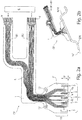
- FIG. 1 shows a schematic plan view of a solution designed according to implantable cuff electrode CE, on its preferably consisting of polyimide carrier substrate 1, in addition to the location-selective detection of neuronal electrical signals and for selective electrical stimulation of individual nerve fibers provided first electrode assembly 2 serving for inhibiting at least one selected nerve fiber second electrode arrangement 7 is applied.
- the second electrode arrangement 7, which extends along the efferent, here to the heart H, leading to signal propagation, comprises two axially spaced second electrode strips 8, between which a second electrode structure 13 is centrally provided which consists of four second electrode surfaces 9 arranged separately from one another.
- All of the electrodes 8, 13 of the second electrode arrangement 2 are connected or connectable to a signal generator 6 'via electrical interconnects L applied to the carrier substrate 1 or integrated therein, which together with the signal detector and generator 6 and with a power source in a separately encapsulated , implantable unit is integrated.
- the electrical interconnects L may optionally have a separable connection structure V.
- the second electrode arrangement 2 comprises optical waveguide arrangements 10, each of which distributes four in the circumferential direction U. arranged, separate optical waveguide openings 11 include.
- the optical waveguides LI to the individual optical waveguide openings or apertures 11 extend within the carrier substrate 1 and can be combined on the proximal side with a uniform light source LQ or with separate light sources LQ different light wavelengths to optogenetically selectively activated stimuli and / or optically activated and selective inhibition along certain To cause nerve fibers.
- the geometric shape and size of the individual electrodes ie, the first and second electrode strips 5, 8 and the first and second electrode surfaces 4, 9 can basically be made individually matched and are particularly based on the diameter of the nerve fiber bundle around which the implantable cuff electrode CF can be applied.
- the extension of the first and second electrode structures and electrode strips oriented in the circumferential direction U and, if appropriate, of the optical waveguide arrangements 10 preferably corresponds to the peripheral edge of the nerve fiber bundle to be wrapped with the cuff electrode CE.
- the axial distance of the tripolar electrode arrangement should preferably be adapted to the diameter and the resulting distance of the so-called Ranvier Schnürringe in myelinated nerve fibers of the nerve fibers to be excited.
- the electrodes are shown as rectangular electrode surfaces. In an advantageous manner, in particular for the purpose of avoiding field line densifications occurring at electrode rectangular edges, it is advisable to form the electrode surfaces at least with rounded corners.
- Electrode strip 5 in about the same length as the axial distance of the rings or slightly larger to choose to reach with sufficiently high statistical probability and the Ranvierschen rings very large fibers. The same applies preferably also to the axial spacing of the second electrode strips 8.
- the total axial extension of the entire cuff electrode CE should be matched to the intracorporeal size ratios of the respective nerve fiber bundles, and typically should not exceed 4 cm.
- the carrier substrate 1 has at least one, preferably two or three openings 14 reinforced by metal ring structures, which serve for fastening the implanted electrode arrangement CF to the nerve fiber bundle.
- the attachment takes place with the aid of a surgical thread which is threaded at least once through the openings 14 and in which the tissue surrounding the nerve fiber bundle is sutured.
- the carrier substrate 1 adjoining the carrier substrate area 1B is in Style of a flat flag laterally from the nerve fiber bundle and protrudes into the surrounding tissue.
- the metal ring structures 14 are intended to help mechanically secure the fastening forces acting along the surgical thread and to prevent drastic damage to the support substrate.
- the second electrode arrangement 7 is placed on the side H leading to the heart along the Nerve fiber bundle to arrange.
- the second, the selective detection and selective stimulation of localized nerve fibers serving electrode assembly 2 is attached along the nerve fiber bundle brain side G.
- the first and second electrode strips 5, 8 and the first and second electrode surfaces 4, 9 are vapor-deposited or sputtered onto the carrier substrate, galvanic amplification is conceivable. Laser structuring of thin metal foils is also possible as a technology.
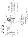
- the electrode strips For permanent joining, in particular of the first and second electrode strips 5, 8 to the carrier substrate 1, the electrode strips have local openings 15, see FIG. 3a through which at least partially the polymer material of the carrier substrate 1 passes or protrudes.
- the electrode surface 16 of each of the first and second electrode strips 5, 8 are otherwise arranged flush with the carrier substrate upper side 1 'and contact the surface of the nerve fiber bundle directly.
- the electrode strips 5, 8 each have a metallic base plate 17, which provides an upper side 18 and a lower side 19. Integrally with the upper side 18 of the base plate 17, orthogonally elevated structural elements 20 are provided over the upper side 18, preferably distributed over the entire upper side, preferably in the form of columnar, ribbed, web or sleeve-like extensions which extend over one of the carrier substrate surface 1 '. facing surface region 21, which can come in direct contact with the epineurium of the nerve fiber bundle.
- an adhesion promoter layer 22 is advantageously provided at least between the underside 19 and the polymer material of the carrier substrate 1 surrounding the base plate 17.
- the adhesion promoter layer 22 can also be applied on the upper side 18.
- Particularly suitable primer layers consist of silicon carbide (SiC) and diamond like Carbon (DLC).
- the electrode strips 5, 8 are made of iridium oxide, which is one of the materials with one of the highest charge transfer capacities.
- FIG Figure 3c shows the longitudinal section through a structural element 20 having an orthogonal to the top 18 of the metallic base plate 17 oriented longitudinal extent LA, along which the structural element 20 at least a second surface portion 23 provides, which is oriented parallel to the top 18 of the metallic base plate 17 and on which Adhesive layer 22 or a bonding agent layer assembly 22 'is applied.
- the second surface region 23 is spaced from the first surface region 18 and completely surrounded by the biocompatible polymer separated by the adhesion promoter layer (22) and the adhesion promoter layer arrangement (22 ').
- the second surface area is as from the Figure 3c can be seen, the upper side 18 of the base plate 17 facing oriented.
- the number and arrangement of the individual structural elements 20 can be chosen arbitrarily, but are preferably geometrically ordered constellations KO, such as. Square, pentagonal, hexagonal or higher order arrangement pattern, as is known from FIG. 3b can be seen.
- geometrically ordered constellations KO such as. Square, pentagonal, hexagonal or higher order arrangement pattern, as is known from FIG. 3b can be seen.
- the base plate 17 is located centrally within the carrier substrate 1, ie the thickness of the biocompatible polymer layer adjacent to the underside 19 of the base plate 17 should be approximately the thickness of the upper surface 18 of the base plate 17 adjacent polymer layer correspond.
- Base plate 17 is associated with the experimentally demonstrable advantage that compensate for the material inherent stresses acting on the base plate 17, which form during an annealing process. The annealing process is required to impress a bias of material into the carrier substrate, through which the implantable sleeve electrode is able to independently wind around the nerve fiber bundle.
- a cuff M which partially encloses the carrier substrate 1 of the implantable cuff electrode CE is shown, which comprises that region of the carrier substrate 1 both on its lower and upper side which adjoins directly to the carrier substrate region 1B and, unlike the carrier substrate region 1B, does not extend in the way of a material-inherent mechanical bias voltage is deformed straight cylindrical shape and brought in this way flush with the epineurium of the nerve fiber bundle in the implanted state in conditioning.
- the sleeve M serves primarily for improved handling of the implantable sleeve electrode CE, which requires particularly careful handling by the surgeon on account of its very low carrier substrate thickness and the filigree electrode arrangements applied to the carrier substrate surface.
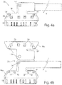
- the sleeve M is preferably formed in one piece and has a sleeve lower part Mu and a sleeve upper part Mo, both of which are hingedly connected via a living hinge hinge 25, see FIGS. 4b and 4c ,
- the sleeve bottom part Mu has a recess 26 embedding the carrier substrate 1 into which the carrier substrate 1 can be inserted.
- the lower sleeve part Mu comprises the carrier substrate 1 in the FIG. 4b removable, framing manner, that is, the lower sleeve part MU protrudes laterally below the carrier substrate 1.
- the sleeve upper part Mo which is connected in one piece to the lower sleeve part Mu via the hinge joint 25, is adapted in shape and size to the lower sleeve part Mu and also has the same shape as the one Cuff bottom part Mu on a the carrier substrate 1 embedding recess 27, so that in the closed state of the sleeve M, the carrier substrate 1 in the in FIG. 4a hermetically, wherein only the carrier substrate region 1B protrudes from the sleeve M.
- the cuff M also serves in particular for improved fixation of the cuff electrode CE relative to the nerve fiber bundle.
- the sleeve upper and lower sides Mo, Mu each provide attachment openings 14 ', see Fig. 4a, b . d , which are congruent with the introduced within the support substrate 1 mounting holes 14 in the collapsed state of the sleeve M are. In this way it is possible to guide a surgical suture 28 through the apertures 14, 14 'of the cuff electrode CE encompassed by the cuff M. In this way, the metal ring encased mounting opening 14 of the sleeve electrode CE can be relieved by the introduced within the sleeve M mounting opening 14 '.
- the sleeve M is made of a stable plastic material, for example of parylene.
- the Mo and Mu can also consist of a polymer hybrid (eg, parylene (inside) and silicone rubber outside). This hybrid has the advantage that the stability of the parylene is combined with the tear strength of the silicone.
- the attachment openings 14 'inside the sleeve M are made reinforced by appropriate material thickening.
- opening windows 29 are introduced, which ensure free access to the reference electrode surfaces 12.
- a cross-section through this is represented by the carrier substrate 1 encompassed by the sleeve M, on the upper side of which reference electrode surfaces 12 are introduced, which remain freely accessible through the opening windows 29 introduced inside the sleeve upper part Mo.
- the opening windows 29 include the reference electrode surfaces 12 with a sloping boundary edge 29 ', so that it is ensured that the Reference electrode surfaces 29 can come into body contact with the surrounding tissue over the entire surface.
- interlocking structures V are arranged between the cuff top and bottom parts Mo, Mu, which consist, for example, of a pin 30 and a recess 31 arranged opposite one another, see FIGS. 4c and f.
- the pins 30 are subjected to force in the corresponding recess 31, in which the pin 31 is held by friction, permanently.
- FIG. 4f the closed state of a locking structure V is illustrated.
- the pin 30 mounted on the sleeve top Mo protrudes through a corresponding opening introduced in the carrier substrate 1 and terminates at the end within the recess 31 of the sleeve base Mu.
- alternative embodiments for the locking structures are conceivable, for example in the form of suitably designed locking mechanisms.
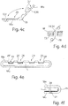
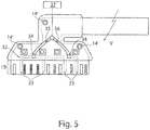
- FIG. 5 another embodiment is illustrated, which facilitates facilitated implantation of the solution formed according to the sleeve electrode CE.
- a fluid channel system 32 is incorporated, which is completely covered by the carrier substrate 1.
- the fluid channel system 32 extends substantially in the region of the carrier substrate region 1B, which assumes the shape of a graduated cylinder due to a material-inherent bias without external force by means of an autonomous self-winding. If, on the other hand, the fluid channel system 32 is filled with a fluid, preferably water, then the water pressure forming along the fluid channel system 32 can just clamp the carrier substrate region 1b against the material-inherent winding forces.
- the fluid channel system 32 has in the circumferential direction of the lateral surface of the self-forming graduated cylinder extending fluid channel branches 33, which force the required extension of the carrier substrate area 1B in the filled state.
- At least two channel openings 34 are provided within the carrier substrate 1, whose size and arrangement are dimensioned such that they fluid-tight at inlet and outlet openings of extending within the sleeve M Fluidzu- or discharges 35, 36 open.
- the inlet and outlet lines 35, 36 running inside the cuff M are fluidically connected to a fluid control system 37, which can be actuated by an operator.
- the fluid channel system 32 is filled with a fluid, whereby the carrier substrate region 1B is stretched.
- the surgeon places the cuff electrode CE exactly at a predetermined position along the nerve bundle.
- the emptying of the fluid channel system 32 is performed by the surgeon, whereby the carrier substrate area 1B automatically wraps around the nerve fiber bundle.
- the cuff electrode CE is fixed to the surrounding tissue with a suture thread through the attachment holes 14 'provided in the cuff.
- the channel openings 34 are provided with metallized contacts, via which an electrical voltage along the leads 35, 36 for deployment of the implantable electrode assembly CE via a correspondingly modified controller 37 can be applied until the electrode is finally placed.
Landscapes
- Health & Medical Sciences (AREA)
- Life Sciences & Earth Sciences (AREA)
- General Health & Medical Sciences (AREA)
- Public Health (AREA)
- Animal Behavior & Ethology (AREA)
- Engineering & Computer Science (AREA)
- Biomedical Technology (AREA)
- Veterinary Medicine (AREA)
- Heart & Thoracic Surgery (AREA)
- Neurology (AREA)
- Neurosurgery (AREA)
- Radiology & Medical Imaging (AREA)
- Nuclear Medicine, Radiotherapy & Molecular Imaging (AREA)
- Cardiology (AREA)
- Orthopedic Medicine & Surgery (AREA)
- Biophysics (AREA)
- Surgery (AREA)
- Molecular Biology (AREA)
- Medical Informatics (AREA)
- Pathology (AREA)
- Physics & Mathematics (AREA)
- Electrotherapy Devices (AREA)
Priority Applications (2)
| Application Number | Priority Date | Filing Date | Title |
|---|---|---|---|
| PL15774937T PL3204105T3 (pl) | 2014-10-07 | 2015-10-07 | Wszczepialny układ elektrodowy |
| HRP20181487TT HRP20181487T1 (hr) | 2014-10-07 | 2015-10-07 | Implantabilna elektrodna naprava |
Applications Claiming Priority (2)
| Application Number | Priority Date | Filing Date | Title |
|---|---|---|---|
| DE102014014927.7A DE102014014927A1 (de) | 2014-10-07 | 2014-10-07 | Implantierbare Elektrodenanordnung |
| PCT/EP2015/073129 WO2016055512A1 (de) | 2014-10-07 | 2015-10-07 | Implantierbare elektrodenanordnung |
Publications (2)
| Publication Number | Publication Date |
|---|---|
| EP3204105A1 EP3204105A1 (de) | 2017-08-16 |
| EP3204105B1 true EP3204105B1 (de) | 2018-08-01 |
Family
ID=54251527
Family Applications (1)
| Application Number | Title | Priority Date | Filing Date |
|---|---|---|---|
| EP15774937.5A Active EP3204105B1 (de) | 2014-10-07 | 2015-10-07 | Implantierbare elektrodenanordnung |
Country Status (14)
| Country | Link |
|---|---|
| US (2) | US11850419B2 (enExample) |
| EP (1) | EP3204105B1 (enExample) |
| JP (1) | JP6644062B2 (enExample) |
| KR (2) | KR102302857B1 (enExample) |
| CN (1) | CN107106062B (enExample) |
| AU (1) | AU2015330072B2 (enExample) |
| CA (1) | CA2962338C (enExample) |
| DE (1) | DE102014014927A1 (enExample) |
| DK (1) | DK3204105T3 (enExample) |
| ES (1) | ES2702881T3 (enExample) |
| HR (1) | HRP20181487T1 (enExample) |
| HU (1) | HUE040315T2 (enExample) |
| PL (1) | PL3204105T3 (enExample) |
| WO (1) | WO2016055512A1 (enExample) |
Cited By (12)
| Publication number | Priority date | Publication date | Assignee | Title |
|---|---|---|---|---|
| DE102019206388A1 (de) * | 2019-05-03 | 2020-11-05 | Neuroloop GmbH | Implantierbare elektrische Kontaktanordnung |
| DE102020117142A1 (de) | 2020-06-30 | 2021-12-30 | Neuroloop GmbH | Medizinisches Handhabungsset |
| DE102022122699B3 (de) | 2022-09-07 | 2024-01-11 | Neuroloop GmbH | Medizinisches Implantat in Form einer Wickelmanschette |
| DE102022133134A1 (de) | 2022-12-13 | 2024-06-13 | Neuroloop GmbH | Medizinisches elektronisches Implantat |
| DE102023104119A1 (de) | 2023-02-20 | 2024-08-22 | Neuroloop GmbH | Elektrische Schaltungsanordnung für eine biomedizinische Schnittstelle |
| DE102023104126A1 (de) | 2023-02-20 | 2024-08-22 | Neuroloop GmbH | Elektrische Schaltungsanordnung zur Erzeugung von stromgesteuerten elektrischen Signalen |
| WO2024223377A1 (de) | 2023-04-27 | 2024-10-31 | Neuroloop GmbH | Mobiles, an eine person anlegbares, elektrisches ladesystem für ein implantat mit einem elektrischen energiespeicher |
| DE102023126302A1 (de) | 2023-09-27 | 2025-03-27 | Neuroloop GmbH | Medizinische implantierbare Anordnung |
| DE102023126618A1 (de) * | 2023-09-29 | 2025-04-03 | Neuroloop GmbH | Manschettenförmiges medizinisches Implantat |
| DE102023126630A1 (de) * | 2023-09-29 | 2025-04-03 | Neuroloop GmbH | Medizinisches Implantat |
| DE102023126781A1 (de) * | 2023-10-02 | 2025-04-03 | Neuroloop GmbH | Manschettenförmiges medizinisches Implantat |
| DE102024107942A1 (de) * | 2024-03-20 | 2025-09-25 | Neuroloop GmbH | Anordnung zur Signal- und Energieversorgung eines medizinischen aktiven Implantats |
Families Citing this family (20)
| Publication number | Priority date | Publication date | Assignee | Title |
|---|---|---|---|---|
| DE102014014927A1 (de) | 2014-10-07 | 2016-04-07 | Neuroloop GmbH | Implantierbare Elektrodenanordnung |
| DE102016222712A1 (de) * | 2016-11-18 | 2018-05-24 | Neuroloop GmbH | Implantierbare elektrische, multipolige Verbindungsstruktur |
| DE102017209773A1 (de) * | 2017-06-09 | 2018-12-13 | Neuroloop GmbH | Implantierbare elektrische Verbindungsstruktur |
| GB2563651A (en) * | 2017-06-22 | 2018-12-26 | Galvani Bioelectronics Ltd | Nerve stimulation and monitoring device |
| EP3691742B1 (en) | 2017-10-02 | 2023-03-29 | Case Western Reserve University | Modified nerve cuff electrode design for stable recording and/or stimulation |
| DE102017222362B4 (de) | 2017-12-11 | 2021-03-04 | Neuroloop GmbH | Vorrichtung zur extravasalen oder extraneuronalen Befestigung eines Implantats |
| US11745010B2 (en) | 2017-12-21 | 2023-09-05 | Galvani Bioelectronics Limited | Nerve stimulation device for current steering |
| EP3727563A1 (en) | 2017-12-21 | 2020-10-28 | Galvani Bioelectronics Limited | Nerve stimulation device for unidirectional stimulation and current steering |
| DE102018204036B4 (de) | 2018-03-16 | 2025-05-08 | Neuroloop GmbH | Implantat in Art einer Wickelmanschetten-Elektrodenanordnung |
| DE102018207709A1 (de) * | 2018-05-17 | 2019-11-21 | Neuroloop GmbH | Vorrichtung zur extravasalen oder extraneuronalen Befestigung eines medizinischen Implantats in Art einer Wickelmanschette |
| DE102018213119A1 (de) * | 2018-08-06 | 2020-02-06 | Neuroloop GmbH | Medizinisches Implantat mit einer als Wickelmanschette ausgebildeten Elektrodenanordnung |
| DE102018213120A1 (de) | 2018-08-06 | 2020-02-06 | Neuroloop GmbH | Medizinisches Implantat in Art einer Wickelmanschetten-Elektrodenanordnung |
| WO2020060881A1 (en) | 2018-09-18 | 2020-03-26 | Verily Life Sciences Llc | Monolithic lead assembly and methods of microfabricating a monolithic lead assembly |
| EP3852864B1 (en) | 2018-09-18 | 2024-12-18 | Verily Life Sciences LLC | Stimulation system with monolithic-lead component connected to skull mount package |
| CN113015552B (zh) | 2018-11-16 | 2025-07-22 | 威里利生命科学有限责任公司 | 用于高密度神经接口的分支近端连接器 |
| AU2021336294A1 (en) | 2020-09-02 | 2023-03-30 | The Alfred E. Mann Foundation For Scientific Research | Electrode leads having multi-application nerve cuffs and associated systems and methods |
| WO2022211946A1 (en) | 2021-03-30 | 2022-10-06 | The Alfred E. Mann Foundation For Scientific Research | Electrode leads having nerve cuffs and associated systems |
| WO2023149911A1 (en) | 2022-02-01 | 2023-08-10 | The Alfred E. Mann Foundation For Scientific Research | Electrode leads having nerve contact elements with coil contacts and associated systems and methods |
| AU2023350980A1 (en) * | 2022-09-29 | 2025-04-03 | The Alfred E. Mann Foundation For Scientific Research | Electrode leads having nerve cuffs and associated systems and methods |
| AU2024262360A1 (en) * | 2023-04-26 | 2025-11-06 | Heather DAWES | Fully implantable speech neuroprosthesis device, system and methods for using same |
Family Cites Families (34)
| Publication number | Priority date | Publication date | Assignee | Title |
|---|---|---|---|---|
| US4969468A (en) * | 1986-06-17 | 1990-11-13 | Alfred E. Mann Foundation For Scientific Research | Electrode array for use in connection with a living body and method of manufacture |
| US5324322A (en) * | 1992-04-20 | 1994-06-28 | Case Western Reserve University | Thin film implantable electrode and method of manufacture |
| US5501703A (en) * | 1994-01-24 | 1996-03-26 | Medtronic, Inc. | Multichannel apparatus for epidural spinal cord stimulator |
| DE4433111A1 (de) | 1994-09-16 | 1996-03-21 | Fraunhofer Ges Forschung | Cuff-Elektrode |
| US6052608A (en) * | 1998-03-30 | 2000-04-18 | Johnson & Johnson Professional, Inc. | Implantable medical electrode contacts |
| DE10020846A1 (de) | 2000-04-28 | 2001-12-06 | Intelligent Implants Gmbh | Mikrokontaktstruktur für Neuroprothesen zur Implantation an Nervengewebe und Verfahren hierzu |
| WO2002030508A2 (en) * | 2000-10-11 | 2002-04-18 | Riso Ronald R | Nerve cuff electrode |
| FR2821275B1 (fr) | 2001-02-28 | 2004-01-30 | Univ Joseph Fourier | Structure d'electrodes implantable |
| US6907293B2 (en) * | 2001-03-30 | 2005-06-14 | Case Western Reserve University | Systems and methods for selectively stimulating components in, on, or near the pudendal nerve or its branches to achieve selective physiologic responses |
| US6600956B2 (en) * | 2001-08-21 | 2003-07-29 | Cyberonics, Inc. | Circumneural electrode assembly |
| US7734355B2 (en) * | 2001-08-31 | 2010-06-08 | Bio Control Medical (B.C.M.) Ltd. | Treatment of disorders by unidirectional nerve stimulation |
| US20140046407A1 (en) * | 2001-08-31 | 2014-02-13 | Bio Control Medical (B.C.M.) Ltd. | Nerve stimulation techniques |
| US7778703B2 (en) | 2001-08-31 | 2010-08-17 | Bio Control Medical (B.C.M.) Ltd. | Selective nerve fiber stimulation for treating heart conditions |
| US20060111626A1 (en) * | 2003-03-27 | 2006-05-25 | Cvrx, Inc. | Electrode structures having anti-inflammatory properties and methods of use |
| US8718791B2 (en) | 2003-05-23 | 2014-05-06 | Bio Control Medical (B.C.M.) Ltd. | Electrode cuffs |
| US6999820B2 (en) * | 2003-05-29 | 2006-02-14 | Advanced Neuromodulation Systems, Inc. | Winged electrode body for spinal cord stimulation |
| US7480532B2 (en) * | 2003-10-22 | 2009-01-20 | Cvrx, Inc. | Baroreflex activation for pain control, sedation and sleep |
| DE10355652A1 (de) * | 2003-11-28 | 2005-06-30 | Forschungszentrum Jülich GmbH | Verfahren und Vorrichtung zur Desynchronisation neuronaler Hirnaktivität |
| US20060004417A1 (en) * | 2004-06-30 | 2006-01-05 | Cvrx, Inc. | Baroreflex activation for arrhythmia treatment |
| US7640057B2 (en) * | 2005-04-25 | 2009-12-29 | Cardiac Pacemakers, Inc. | Methods of providing neural markers for sensed autonomic nervous system activity |
| WO2007010441A2 (en) * | 2005-07-21 | 2007-01-25 | Koninklijke Philips Electronics N.V. | Apparatus and method for coupling implanted electrodes to nervous tissue |
| WO2007149465A2 (en) * | 2006-06-19 | 2007-12-27 | Second Sight Medical Products, Inc. | Electrode with increased stability and method of manufacturing the same |
| DE202007019439U1 (de) * | 2006-10-13 | 2012-09-12 | Apnex Medical, Inc. | Geräte, Systeme und Methoden zur Behandlung von obstruktiver Schalfapnoe |
| WO2009046764A1 (en) | 2007-10-10 | 2009-04-16 | Neurotech S.A. | Neurostimulator and method for regulting the same |
| EP3002034A1 (en) * | 2008-09-26 | 2016-04-06 | Pixium Vision SA | Electrode array and method of manufacturing same |
| US8870857B2 (en) * | 2009-11-05 | 2014-10-28 | Greatbatch Ltd. | Waveguide neural interface device |
| EP2477467B1 (en) * | 2011-01-14 | 2017-07-26 | Second Sight Medical Products, Inc. | Method of manufacturing a flexible circuit electrode array |
| CN104053473B (zh) * | 2011-09-30 | 2016-04-27 | 尼科索亚股份有限公司 | 配置用于植入的调节器装置 |
| US20130172973A1 (en) * | 2012-01-04 | 2013-07-04 | Bruce A. Tockman | Neural stimulation device with insulating sheath |
| CN104582787A (zh) * | 2012-04-02 | 2015-04-29 | 生物控制医疗(Bcm)有限公司 | 电极环带 |
| WO2013188871A1 (en) * | 2012-06-15 | 2013-12-19 | Case Western Reserve University | Implantable cuff and method for functional electrical stimulation and monitoring |
| TWI498101B (zh) * | 2012-08-30 | 2015-09-01 | Univ Nat Chiao Tung | 神經纖維分佈之分析方法及標準化誘發復合動作電位之量測方法 |
| KR101450859B1 (ko) * | 2012-10-10 | 2014-10-15 | 한국과학기술연구원 | 염증 억제용 약물을 구비한 신경 전극 및 그 제조 방법 |
| DE102014014927A1 (de) | 2014-10-07 | 2016-04-07 | Neuroloop GmbH | Implantierbare Elektrodenanordnung |
-
2014
- 2014-10-07 DE DE102014014927.7A patent/DE102014014927A1/de not_active Withdrawn
-
2015
- 2015-10-07 JP JP2017519231A patent/JP6644062B2/ja active Active
- 2015-10-07 HR HRP20181487TT patent/HRP20181487T1/hr unknown
- 2015-10-07 KR KR1020187004241A patent/KR102302857B1/ko active Active
- 2015-10-07 US US15/517,903 patent/US11850419B2/en active Active
- 2015-10-07 ES ES15774937T patent/ES2702881T3/es active Active
- 2015-10-07 CN CN201580054335.4A patent/CN107106062B/zh active Active
- 2015-10-07 HU HUE15774937A patent/HUE040315T2/hu unknown
- 2015-10-07 DK DK15774937.5T patent/DK3204105T3/en active
- 2015-10-07 EP EP15774937.5A patent/EP3204105B1/de active Active
- 2015-10-07 PL PL15774937T patent/PL3204105T3/pl unknown
- 2015-10-07 WO PCT/EP2015/073129 patent/WO2016055512A1/de not_active Ceased
- 2015-10-07 KR KR1020177009385A patent/KR101831116B1/ko active Active
- 2015-10-07 CA CA2962338A patent/CA2962338C/en active Active
- 2015-10-07 AU AU2015330072A patent/AU2015330072B2/en active Active
-
2023
- 2023-11-08 US US18/504,281 patent/US12343523B2/en active Active
Cited By (24)
| Publication number | Priority date | Publication date | Assignee | Title |
|---|---|---|---|---|
| WO2020225090A1 (de) | 2019-05-03 | 2020-11-12 | Neuroloop GmbH | Implantierbare elektrische kontaktanordnung |
| US12324911B2 (en) | 2019-05-03 | 2025-06-10 | Neuroloop GmbH | Implantable electrical contact arrangement |
| DE102019206388A1 (de) * | 2019-05-03 | 2020-11-05 | Neuroloop GmbH | Implantierbare elektrische Kontaktanordnung |
| US12485289B2 (en) | 2020-06-30 | 2025-12-02 | Neuroloop GmbH | Medical handling set |
| DE102020117142A1 (de) | 2020-06-30 | 2021-12-30 | Neuroloop GmbH | Medizinisches Handhabungsset |
| WO2022002543A1 (de) | 2020-06-30 | 2022-01-06 | Neuroloop GmbH | Medizinisches handhabungsset |
| DE102022122699B3 (de) | 2022-09-07 | 2024-01-11 | Neuroloop GmbH | Medizinisches Implantat in Form einer Wickelmanschette |
| WO2024052274A1 (de) | 2022-09-07 | 2024-03-14 | Neuroloop GmbH | Medizinisches implantat in form einer wickelmanschette |
| DE102022133134A1 (de) | 2022-12-13 | 2024-06-13 | Neuroloop GmbH | Medizinisches elektronisches Implantat |
| WO2024175496A1 (de) | 2023-02-20 | 2024-08-29 | Neuroloop GmbH | Elektrische schaltungsanordnung zur erzeugung von stromgesteuerten elektrischen signalen |
| WO2024175272A1 (de) | 2023-02-20 | 2024-08-29 | Neuroloop GmbH | Elektrische schaltungsanordnung für eine biomedizinische schnittstelle |
| DE102023104126A1 (de) | 2023-02-20 | 2024-08-22 | Neuroloop GmbH | Elektrische Schaltungsanordnung zur Erzeugung von stromgesteuerten elektrischen Signalen |
| DE102023104119A1 (de) | 2023-02-20 | 2024-08-22 | Neuroloop GmbH | Elektrische Schaltungsanordnung für eine biomedizinische Schnittstelle |
| DE102023110861A1 (de) | 2023-04-27 | 2024-10-31 | Neuroloop GmbH | Mobiles, an eine Person anlegbares, elektrisches Ladesystem für ein Implantat mit einem elektrischen Energiespeicher |
| WO2024223377A1 (de) | 2023-04-27 | 2024-10-31 | Neuroloop GmbH | Mobiles, an eine person anlegbares, elektrisches ladesystem für ein implantat mit einem elektrischen energiespeicher |
| WO2025068275A1 (de) | 2023-09-27 | 2025-04-03 | Neuroloop GmbH | Medizinische implantierbare anordnung in art einer wickelmanschette |
| DE102023126302A1 (de) | 2023-09-27 | 2025-03-27 | Neuroloop GmbH | Medizinische implantierbare Anordnung |
| DE102023126618A1 (de) * | 2023-09-29 | 2025-04-03 | Neuroloop GmbH | Manschettenförmiges medizinisches Implantat |
| WO2025068270A1 (de) | 2023-09-29 | 2025-04-03 | Neuroloop GmbH | Manschettenförmiges medizinisches implantat |
| DE102023126630A1 (de) * | 2023-09-29 | 2025-04-03 | Neuroloop GmbH | Medizinisches Implantat |
| WO2025068277A1 (de) | 2023-09-29 | 2025-04-03 | Neuroloop GmbH | Medizinisches implantat |
| DE102023126781A1 (de) * | 2023-10-02 | 2025-04-03 | Neuroloop GmbH | Manschettenförmiges medizinisches Implantat |
| WO2025073552A1 (de) | 2023-10-02 | 2025-04-10 | Neuroloop GmbH | Manschettenförmiges medizinisches implantat |
| DE102024107942A1 (de) * | 2024-03-20 | 2025-09-25 | Neuroloop GmbH | Anordnung zur Signal- und Energieversorgung eines medizinischen aktiven Implantats |
Also Published As
| Publication number | Publication date |
|---|---|
| HRP20181487T1 (hr) | 2018-11-16 |
| CN107106062A (zh) | 2017-08-29 |
| CA2962338C (en) | 2022-10-25 |
| US20170319846A1 (en) | 2017-11-09 |
| ES2702881T3 (es) | 2019-03-06 |
| AU2015330072A1 (en) | 2017-04-20 |
| KR102302857B1 (ko) | 2021-09-15 |
| HUE040315T2 (hu) | 2019-02-28 |
| US12343523B2 (en) | 2025-07-01 |
| PL3204105T3 (pl) | 2019-01-31 |
| US20240075281A1 (en) | 2024-03-07 |
| JP2017530806A (ja) | 2017-10-19 |
| CN107106062B (zh) | 2020-08-11 |
| KR20180019757A (ko) | 2018-02-26 |
| KR101831116B1 (ko) | 2018-04-04 |
| WO2016055512A1 (de) | 2016-04-14 |
| EP3204105A1 (de) | 2017-08-16 |
| DK3204105T3 (en) | 2018-11-19 |
| DE102014014927A1 (de) | 2016-04-07 |
| JP6644062B2 (ja) | 2020-02-12 |
| US11850419B2 (en) | 2023-12-26 |
| KR20170042808A (ko) | 2017-04-19 |
| AU2015330072B2 (en) | 2020-02-13 |
| CA2962338A1 (en) | 2016-04-14 |
Similar Documents
| Publication | Publication Date | Title |
|---|---|---|
| EP3204105B1 (de) | Implantierbare elektrodenanordnung | |
| EP3204111B1 (de) | Implantierbare anordnung | |
| DE60124948T2 (de) | Leitungen für die gerichtete Hirnstimulation und-aufzeichnung | |
| DE60207216T2 (de) | Leitung mit zwischen elektroden einstellbaren winkel- und raumpositionen | |
| DE69727221T2 (de) | Technik zur epilepsiebehandlung durch hirnzellenanregung und medikamenteninfusion | |
| DE69737402T2 (de) | Vorrichtung zur Behandlung von neurodegenerativen Störungen | |
| Linderoth et al. | Peripheral vasodilatation after spinal cord stimulation: animal studies of putative effector mechanisms | |
| DE60116551T2 (de) | Elektrodenleitungen zur Rückenmarkstimulation | |
| DE60126689T2 (de) | Stimulationskatheter mit Elektrode und Faseroptik | |
| McCreery et al. | Stimulus parameters affecting tissue injury during microstimulation in the cochlear nucleus of the cat | |
| EP0784992B1 (de) | Vorrichtung zum Behandeln von malignen Gewebsveränderungen | |
| EP3145581B1 (de) | Therapeutisch anwendbare mehrkanal- gleichstromabgabevorrichtung | |
| DE10151650A1 (de) | Elektrodenanordnung zur elektrischen Stimulation von biologischem Material sowie Multielektrodenarray zur Verwendung in einer solchen | |
| CA2826036A1 (en) | Leads with spirally arranged segmented electrodes and methods of making and using the leads | |
| DE3518317C2 (enExample) | ||
| US20210101010A1 (en) | Transdural electrode device for stimulation of the spinal cord | |
| WO2010112023A2 (de) | Stimulationselektrode | |
| CH384730A (de) | Vorrichtung für elektrische Therapie | |
| DE10033400A1 (de) | System zum Bereitstellen von elektrischen Stimulationen für medizinische Zwecke | |
| Slopsema et al. | Advancing directional deep brain stimulation array technology | |
| DE10113988A1 (de) | Medizinisches Gerät mit einer elektrischen Ladung zur Verbesserung des Anhaftens von Gewebe | |
| DE102004002379A1 (de) | Neurologisches Werkzeug | |
| DE20003952U1 (de) | Gerät zum Zerstören von Zellgewebe |
Legal Events
| Date | Code | Title | Description |
|---|---|---|---|
| PUAI | Public reference made under article 153(3) epc to a published international application that has entered the european phase |
Free format text: ORIGINAL CODE: 0009012 |
|
| 17P | Request for examination filed |
Effective date: 20170425 |
|
| AK | Designated contracting states |
Kind code of ref document: A1 Designated state(s): AL AT BE BG CH CY CZ DE DK EE ES FI FR GB GR HR HU IE IS IT LI LT LU LV MC MK MT NL NO PL PT RO RS SE SI SK SM TR |
|
| AX | Request for extension of the european patent |
Extension state: BA ME |
|
| DAV | Request for validation of the european patent (deleted) | ||
| DAX | Request for extension of the european patent (deleted) | ||
| GRAP | Despatch of communication of intention to grant a patent |
Free format text: ORIGINAL CODE: EPIDOSNIGR1 |
|
| INTG | Intention to grant announced |
Effective date: 20180314 |
|
| GRAS | Grant fee paid |
Free format text: ORIGINAL CODE: EPIDOSNIGR3 |
|
| GRAA | (expected) grant |
Free format text: ORIGINAL CODE: 0009210 |
|
| AK | Designated contracting states |
Kind code of ref document: B1 Designated state(s): AL AT BE BG CH CY CZ DE DK EE ES FI FR GB GR HR HU IE IS IT LI LT LU LV MC MK MT NL NO PL PT RO RS SE SI SK SM TR |
|
| REG | Reference to a national code |
Ref country code: GB Ref legal event code: FG4D Free format text: NOT ENGLISH |
|
| REG | Reference to a national code |
Ref country code: CH Ref legal event code: EP Ref country code: AT Ref legal event code: REF Ref document number: 1023602 Country of ref document: AT Kind code of ref document: T Effective date: 20180815 |
|
| REG | Reference to a national code |
Ref country code: IE Ref legal event code: FG4D Free format text: LANGUAGE OF EP DOCUMENT: GERMAN |
|
| REG | Reference to a national code |
Ref country code: DE Ref legal event code: R096 Ref document number: 502015005323 Country of ref document: DE |
|
| REG | Reference to a national code |
Ref country code: CH Ref legal event code: NV Representative=s name: BOLIS AND ASSOCIATES LLC INTELLECTUAL PROPERTY, CH |
|
| REG | Reference to a national code |
Ref country code: HR Ref legal event code: TUEP Ref document number: P20181487 Country of ref document: HR |
|
| REG | Reference to a national code |
Ref country code: FR Ref legal event code: PLFP Year of fee payment: 4 |
|
| REG | Reference to a national code |
Ref country code: NL Ref legal event code: FP |
|
| REG | Reference to a national code |
Ref country code: HR Ref legal event code: T1PR Ref document number: P20181487 Country of ref document: HR |
|
| REG | Reference to a national code |
Ref country code: DK Ref legal event code: T3 Effective date: 20181114 |
|
| REG | Reference to a national code |
Ref country code: SE Ref legal event code: TRGR |
|
| REG | Reference to a national code |
Ref country code: NO Ref legal event code: T2 Effective date: 20180801 |
|
| REG | Reference to a national code |
Ref country code: LT Ref legal event code: MG4D |
|
| PG25 | Lapsed in a contracting state [announced via postgrant information from national office to epo] |
Ref country code: GR Free format text: LAPSE BECAUSE OF FAILURE TO SUBMIT A TRANSLATION OF THE DESCRIPTION OR TO PAY THE FEE WITHIN THE PRESCRIBED TIME-LIMIT Effective date: 20181102 Ref country code: PT Free format text: LAPSE BECAUSE OF FAILURE TO SUBMIT A TRANSLATION OF THE DESCRIPTION OR TO PAY THE FEE WITHIN THE PRESCRIBED TIME-LIMIT Effective date: 20181203 Ref country code: IS Free format text: LAPSE BECAUSE OF FAILURE TO SUBMIT A TRANSLATION OF THE DESCRIPTION OR TO PAY THE FEE WITHIN THE PRESCRIBED TIME-LIMIT Effective date: 20181201 Ref country code: RS Free format text: LAPSE BECAUSE OF FAILURE TO SUBMIT A TRANSLATION OF THE DESCRIPTION OR TO PAY THE FEE WITHIN THE PRESCRIBED TIME-LIMIT Effective date: 20180801 Ref country code: LT Free format text: LAPSE BECAUSE OF FAILURE TO SUBMIT A TRANSLATION OF THE DESCRIPTION OR TO PAY THE FEE WITHIN THE PRESCRIBED TIME-LIMIT Effective date: 20180801 Ref country code: BG Free format text: LAPSE BECAUSE OF FAILURE TO SUBMIT A TRANSLATION OF THE DESCRIPTION OR TO PAY THE FEE WITHIN THE PRESCRIBED TIME-LIMIT Effective date: 20181101 |
|
| PG25 | Lapsed in a contracting state [announced via postgrant information from national office to epo] |
Ref country code: LV Free format text: LAPSE BECAUSE OF FAILURE TO SUBMIT A TRANSLATION OF THE DESCRIPTION OR TO PAY THE FEE WITHIN THE PRESCRIBED TIME-LIMIT Effective date: 20180801 Ref country code: AL Free format text: LAPSE BECAUSE OF FAILURE TO SUBMIT A TRANSLATION OF THE DESCRIPTION OR TO PAY THE FEE WITHIN THE PRESCRIBED TIME-LIMIT Effective date: 20180801 |
|
| REG | Reference to a national code |
Ref country code: HU Ref legal event code: AG4A Ref document number: E040315 Country of ref document: HU |
|
| REG | Reference to a national code |
Ref country code: ES Ref legal event code: FG2A Ref document number: 2702881 Country of ref document: ES Kind code of ref document: T3 Effective date: 20190306 |
|
| PG25 | Lapsed in a contracting state [announced via postgrant information from national office to epo] |
Ref country code: EE Free format text: LAPSE BECAUSE OF FAILURE TO SUBMIT A TRANSLATION OF THE DESCRIPTION OR TO PAY THE FEE WITHIN THE PRESCRIBED TIME-LIMIT Effective date: 20180801 Ref country code: RO Free format text: LAPSE BECAUSE OF FAILURE TO SUBMIT A TRANSLATION OF THE DESCRIPTION OR TO PAY THE FEE WITHIN THE PRESCRIBED TIME-LIMIT Effective date: 20180801 Ref country code: CZ Free format text: LAPSE BECAUSE OF FAILURE TO SUBMIT A TRANSLATION OF THE DESCRIPTION OR TO PAY THE FEE WITHIN THE PRESCRIBED TIME-LIMIT Effective date: 20180801 |
|
| REG | Reference to a national code |
Ref country code: DE Ref legal event code: R097 Ref document number: 502015005323 Country of ref document: DE |
|
| PG25 | Lapsed in a contracting state [announced via postgrant information from national office to epo] |
Ref country code: SK Free format text: LAPSE BECAUSE OF FAILURE TO SUBMIT A TRANSLATION OF THE DESCRIPTION OR TO PAY THE FEE WITHIN THE PRESCRIBED TIME-LIMIT Effective date: 20180801 Ref country code: SM Free format text: LAPSE BECAUSE OF FAILURE TO SUBMIT A TRANSLATION OF THE DESCRIPTION OR TO PAY THE FEE WITHIN THE PRESCRIBED TIME-LIMIT Effective date: 20180801 |
|
| PLBE | No opposition filed within time limit |
Free format text: ORIGINAL CODE: 0009261 |
|
| STAA | Information on the status of an ep patent application or granted ep patent |
Free format text: STATUS: NO OPPOSITION FILED WITHIN TIME LIMIT |
|
| PG25 | Lapsed in a contracting state [announced via postgrant information from national office to epo] |
Ref country code: LU Free format text: LAPSE BECAUSE OF NON-PAYMENT OF DUE FEES Effective date: 20181007 Ref country code: MC Free format text: LAPSE BECAUSE OF FAILURE TO SUBMIT A TRANSLATION OF THE DESCRIPTION OR TO PAY THE FEE WITHIN THE PRESCRIBED TIME-LIMIT Effective date: 20180801 |
|
| 26N | No opposition filed |
Effective date: 20190503 |
|
| PG25 | Lapsed in a contracting state [announced via postgrant information from national office to epo] |
Ref country code: SI Free format text: LAPSE BECAUSE OF FAILURE TO SUBMIT A TRANSLATION OF THE DESCRIPTION OR TO PAY THE FEE WITHIN THE PRESCRIBED TIME-LIMIT Effective date: 20180801 |
|
| REG | Reference to a national code |
Ref country code: HR Ref legal event code: ODRP Ref document number: P20181487 Country of ref document: HR Payment date: 20190926 Year of fee payment: 5 |
|
| PG25 | Lapsed in a contracting state [announced via postgrant information from national office to epo] |
Ref country code: MT Free format text: LAPSE BECAUSE OF FAILURE TO SUBMIT A TRANSLATION OF THE DESCRIPTION OR TO PAY THE FEE WITHIN THE PRESCRIBED TIME-LIMIT Effective date: 20180801 |
|
| PG25 | Lapsed in a contracting state [announced via postgrant information from national office to epo] |
Ref country code: TR Free format text: LAPSE BECAUSE OF FAILURE TO SUBMIT A TRANSLATION OF THE DESCRIPTION OR TO PAY THE FEE WITHIN THE PRESCRIBED TIME-LIMIT Effective date: 20180801 |
|
| PG25 | Lapsed in a contracting state [announced via postgrant information from national office to epo] |
Ref country code: CY Free format text: LAPSE BECAUSE OF FAILURE TO SUBMIT A TRANSLATION OF THE DESCRIPTION OR TO PAY THE FEE WITHIN THE PRESCRIBED TIME-LIMIT Effective date: 20180801 Ref country code: MK Free format text: LAPSE BECAUSE OF NON-PAYMENT OF DUE FEES Effective date: 20180801 |
|
| REG | Reference to a national code |
Ref country code: HR Ref legal event code: ODRP Ref document number: P20181487 Country of ref document: HR Payment date: 20200929 Year of fee payment: 6 |
|
| REG | Reference to a national code |
Ref country code: HR Ref legal event code: ODRP Ref document number: P20181487 Country of ref document: HR Payment date: 20210929 Year of fee payment: 7 |
|
| REG | Reference to a national code |
Ref country code: HR Ref legal event code: ODRP Ref document number: P20181487 Country of ref document: HR Payment date: 20220930 Year of fee payment: 8 |
|
| REG | Reference to a national code |
Ref country code: HR Ref legal event code: ODRP Ref document number: P20181487 Country of ref document: HR Payment date: 20230928 Year of fee payment: 9 |
|
| P01 | Opt-out of the competence of the unified patent court (upc) registered |
Effective date: 20231012 |
|
| REG | Reference to a national code |
Ref country code: HR Ref legal event code: ODRP Ref document number: P20181487 Country of ref document: HR Payment date: 20241003 Year of fee payment: 10 |
|
| PGFP | Annual fee paid to national office [announced via postgrant information from national office to epo] |
Ref country code: PL Payment date: 20240925 Year of fee payment: 10 |
|
| PGFP | Annual fee paid to national office [announced via postgrant information from national office to epo] |
Ref country code: NO Payment date: 20241022 Year of fee payment: 10 |
|
| PGFP | Annual fee paid to national office [announced via postgrant information from national office to epo] |
Ref country code: DK Payment date: 20241023 Year of fee payment: 10 |
|
| PGFP | Annual fee paid to national office [announced via postgrant information from national office to epo] |
Ref country code: BE Payment date: 20241022 Year of fee payment: 10 Ref country code: FI Payment date: 20241022 Year of fee payment: 10 |
|
| PGFP | Annual fee paid to national office [announced via postgrant information from national office to epo] |
Ref country code: GB Payment date: 20241024 Year of fee payment: 10 |
|
| PGFP | Annual fee paid to national office [announced via postgrant information from national office to epo] |
Ref country code: FR Payment date: 20241024 Year of fee payment: 10 Ref country code: AT Payment date: 20241021 Year of fee payment: 10 |
|
| PGFP | Annual fee paid to national office [announced via postgrant information from national office to epo] |
Ref country code: HR Payment date: 20241003 Year of fee payment: 10 Ref country code: IE Payment date: 20241018 Year of fee payment: 10 |
|
| PGFP | Annual fee paid to national office [announced via postgrant information from national office to epo] |
Ref country code: IT Payment date: 20241031 Year of fee payment: 10 Ref country code: ES Payment date: 20241118 Year of fee payment: 10 |
|
| PGFP | Annual fee paid to national office [announced via postgrant information from national office to epo] |
Ref country code: SE Payment date: 20241023 Year of fee payment: 10 |
|
| PGFP | Annual fee paid to national office [announced via postgrant information from national office to epo] |
Ref country code: CH Payment date: 20241101 Year of fee payment: 10 |
|
| REG | Reference to a national code |
Ref country code: HR Ref legal event code: ODRP Ref document number: P20181487 Country of ref document: HR Payment date: 20250930 Year of fee payment: 11 |
|
| REG | Reference to a national code |
Ref country code: CH Ref legal event code: U11 Free format text: ST27 STATUS EVENT CODE: U-0-0-U10-U11 (AS PROVIDED BY THE NATIONAL OFFICE) Effective date: 20251101 |
|
| PGFP | Annual fee paid to national office [announced via postgrant information from national office to epo] |
Ref country code: HU Payment date: 20250930 Year of fee payment: 11 |
|
| PGFP | Annual fee paid to national office [announced via postgrant information from national office to epo] |
Ref country code: NL Payment date: 20251023 Year of fee payment: 11 |
|
| PGFP | Annual fee paid to national office [announced via postgrant information from national office to epo] |
Ref country code: DE Payment date: 20251020 Year of fee payment: 11 |