EP3204105B1 - Implantable electrode arrangement - Google Patents
Implantable electrode arrangement Download PDFInfo
- Publication number
- EP3204105B1 EP3204105B1 EP15774937.5A EP15774937A EP3204105B1 EP 3204105 B1 EP3204105 B1 EP 3204105B1 EP 15774937 A EP15774937 A EP 15774937A EP 3204105 B1 EP3204105 B1 EP 3204105B1
- Authority
- EP
- European Patent Office
- Prior art keywords
- electrode
- carrier substrate
- electrode device
- strips
- extension
- Prior art date
- Legal status (The legal status is an assumption and is not a legal conclusion. Google has not performed a legal analysis and makes no representation as to the accuracy of the status listed.)
- Active
Links
- 239000000758 substrate Substances 0.000 claims description 128
- 230000000638 stimulation Effects 0.000 claims description 28
- 230000001537 neural effect Effects 0.000 claims description 15
- 239000000835 fiber Substances 0.000 claims description 14
- 230000003287 optical effect Effects 0.000 claims description 14
- 229920000249 biocompatible polymer Polymers 0.000 claims description 12
- 210000005036 nerve Anatomy 0.000 claims description 11
- 239000000463 material Substances 0.000 claims description 9
- 239000007767 bonding agent Substances 0.000 claims description 5
- BASFCYQUMIYNBI-UHFFFAOYSA-N platinum Chemical compound [Pt] BASFCYQUMIYNBI-UHFFFAOYSA-N 0.000 claims description 4
- 229920000642 polymer Polymers 0.000 claims description 4
- 238000012546 transfer Methods 0.000 claims description 4
- 238000013461 design Methods 0.000 claims description 3
- HTXDPTMKBJXEOW-UHFFFAOYSA-N dioxoiridium Chemical compound O=[Ir]=O HTXDPTMKBJXEOW-UHFFFAOYSA-N 0.000 claims description 3
- 229910000457 iridium oxide Inorganic materials 0.000 claims description 3
- 206010061218 Inflammation Diseases 0.000 claims description 2
- 229920001940 conductive polymer Polymers 0.000 claims description 2
- 230000004054 inflammatory process Effects 0.000 claims description 2
- 229910052697 platinum Inorganic materials 0.000 claims description 2
- 239000007769 metal material Substances 0.000 claims 4
- 239000013543 active substance Substances 0.000 claims 1
- 210000004126 nerve fiber Anatomy 0.000 description 112
- 239000012530 fluid Substances 0.000 description 16
- 239000010410 layer Substances 0.000 description 15
- 230000036772 blood pressure Effects 0.000 description 13
- 238000001514 detection method Methods 0.000 description 11
- 230000005764 inhibitory process Effects 0.000 description 10
- 239000002318 adhesion promoter Substances 0.000 description 8
- 210000000578 peripheral nerve Anatomy 0.000 description 8
- 210000001186 vagus nerve Anatomy 0.000 description 8
- 210000004556 brain Anatomy 0.000 description 7
- 230000000875 corresponding effect Effects 0.000 description 7
- 230000002401 inhibitory effect Effects 0.000 description 7
- 229920001721 polyimide Polymers 0.000 description 7
- 239000004642 Polyimide Substances 0.000 description 6
- 230000000694 effects Effects 0.000 description 6
- 230000035581 baroreflex Effects 0.000 description 5
- 230000007246 mechanism Effects 0.000 description 5
- 229910052751 metal Inorganic materials 0.000 description 5
- 239000002184 metal Substances 0.000 description 5
- 206010020772 Hypertension Diseases 0.000 description 4
- 230000008901 benefit Effects 0.000 description 4
- 238000002513 implantation Methods 0.000 description 4
- 241001465754 Metazoa Species 0.000 description 3
- 241000700159 Rattus Species 0.000 description 3
- 239000008280 blood Substances 0.000 description 3
- 210000004369 blood Anatomy 0.000 description 3
- 210000000133 brain stem Anatomy 0.000 description 3
- 230000015556 catabolic process Effects 0.000 description 3
- 238000006731 degradation reaction Methods 0.000 description 3
- 230000036541 health Effects 0.000 description 3
- 229920000052 poly(p-xylylene) Polymers 0.000 description 3
- 239000002861 polymer material Substances 0.000 description 3
- 230000009467 reduction Effects 0.000 description 3
- 206010010904 Convulsion Diseases 0.000 description 2
- 230000003213 activating effect Effects 0.000 description 2
- 230000003321 amplification Effects 0.000 description 2
- 238000000137 annealing Methods 0.000 description 2
- 239000002220 antihypertensive agent Substances 0.000 description 2
- 229940127088 antihypertensive drug Drugs 0.000 description 2
- 238000013459 approach Methods 0.000 description 2
- 230000036471 bradycardia Effects 0.000 description 2
- 208000006218 bradycardia Diseases 0.000 description 2
- 238000006243 chemical reaction Methods 0.000 description 2
- 239000004020 conductor Substances 0.000 description 2
- 230000001419 dependent effect Effects 0.000 description 2
- 206010015037 epilepsy Diseases 0.000 description 2
- 238000002474 experimental method Methods 0.000 description 2
- 239000011888 foil Substances 0.000 description 2
- 239000007943 implant Substances 0.000 description 2
- 230000007794 irritation Effects 0.000 description 2
- 238000000034 method Methods 0.000 description 2
- 230000007383 nerve stimulation Effects 0.000 description 2
- 238000003199 nucleic acid amplification method Methods 0.000 description 2
- 239000013307 optical fiber Substances 0.000 description 2
- 230000002093 peripheral effect Effects 0.000 description 2
- 230000010287 polarization Effects 0.000 description 2
- 230000008569 process Effects 0.000 description 2
- 238000011160 research Methods 0.000 description 2
- 230000008054 signal transmission Effects 0.000 description 2
- 230000001225 therapeutic effect Effects 0.000 description 2
- 238000002560 therapeutic procedure Methods 0.000 description 2
- XLYOFNOQVPJJNP-UHFFFAOYSA-N water Substances O XLYOFNOQVPJJNP-UHFFFAOYSA-N 0.000 description 2
- 238000004804 winding Methods 0.000 description 2
- SGTNSNPWRIOYBX-UHFFFAOYSA-N 2-(3,4-dimethoxyphenyl)-5-{[2-(3,4-dimethoxyphenyl)ethyl](methyl)amino}-2-(propan-2-yl)pentanenitrile Chemical compound C1=C(OC)C(OC)=CC=C1CCN(C)CCCC(C#N)(C(C)C)C1=CC=C(OC)C(OC)=C1 SGTNSNPWRIOYBX-UHFFFAOYSA-N 0.000 description 1
- 239000005541 ACE inhibitor Substances 0.000 description 1
- 206010006102 Bradypnoea Diseases 0.000 description 1
- OKTJSMMVPCPJKN-UHFFFAOYSA-N Carbon Chemical compound [C] OKTJSMMVPCPJKN-UHFFFAOYSA-N 0.000 description 1
- 206010019280 Heart failures Diseases 0.000 description 1
- 208000001953 Hypotension Diseases 0.000 description 1
- 230000004913 activation Effects 0.000 description 1
- 239000012790 adhesive layer Substances 0.000 description 1
- 238000004873 anchoring Methods 0.000 description 1
- 229940044094 angiotensin-converting-enzyme inhibitor Drugs 0.000 description 1
- 230000003276 anti-hypertensive effect Effects 0.000 description 1
- 210000002376 aorta thoracic Anatomy 0.000 description 1
- 208000037849 arterial hypertension Diseases 0.000 description 1
- 208000006673 asthma Diseases 0.000 description 1
- 230000004323 axial length Effects 0.000 description 1
- 108091008698 baroreceptors Proteins 0.000 description 1
- 230000006399 behavior Effects 0.000 description 1
- 239000002876 beta blocker Substances 0.000 description 1
- 229940097320 beta blocking agent Drugs 0.000 description 1
- 230000005540 biological transmission Effects 0.000 description 1
- 230000015572 biosynthetic process Effects 0.000 description 1
- 210000004204 blood vessel Anatomy 0.000 description 1
- 208000024336 bradypnea Diseases 0.000 description 1
- 229910052799 carbon Inorganic materials 0.000 description 1
- 230000000747 cardiac effect Effects 0.000 description 1
- 239000003795 chemical substances by application Substances 0.000 description 1
- 230000001684 chronic effect Effects 0.000 description 1
- 230000003750 conditioning effect Effects 0.000 description 1
- 230000001276 controlling effect Effects 0.000 description 1
- 230000002596 correlated effect Effects 0.000 description 1
- 230000001186 cumulative effect Effects 0.000 description 1
- 238000000280 densification Methods 0.000 description 1
- 230000002999 depolarising effect Effects 0.000 description 1
- 238000011161 development Methods 0.000 description 1
- 230000018109 developmental process Effects 0.000 description 1
- 229910003460 diamond Inorganic materials 0.000 description 1
- 239000010432 diamond Substances 0.000 description 1
- 201000010099 disease Diseases 0.000 description 1
- 208000037265 diseases, disorders, signs and symptoms Diseases 0.000 description 1
- 239000003814 drug Substances 0.000 description 1
- 229940079593 drug Drugs 0.000 description 1
- 230000002526 effect on cardiovascular system Effects 0.000 description 1
- 239000012636 effector Substances 0.000 description 1
- 239000007772 electrode material Substances 0.000 description 1
- 238000005516 engineering process Methods 0.000 description 1
- 238000011156 evaluation Methods 0.000 description 1
- 238000009432 framing Methods 0.000 description 1
- 230000003284 homeostatic effect Effects 0.000 description 1
- 230000001631 hypertensive effect Effects 0.000 description 1
- 230000028709 inflammatory response Effects 0.000 description 1
- 230000010354 integration Effects 0.000 description 1
- 238000011835 investigation Methods 0.000 description 1
- 230000002045 lasting effect Effects 0.000 description 1
- 239000007788 liquid Substances 0.000 description 1
- 208000012866 low blood pressure Diseases 0.000 description 1
- 210000003666 myelinated nerve fiber Anatomy 0.000 description 1
- 230000004751 neurological system process Effects 0.000 description 1
- 230000003227 neuromodulating effect Effects 0.000 description 1
- 230000004007 neuromodulation Effects 0.000 description 1
- 230000008555 neuronal activation Effects 0.000 description 1
- 239000004033 plastic Substances 0.000 description 1
- 229920001296 polysiloxane Polymers 0.000 description 1
- 210000001774 pressoreceptor Anatomy 0.000 description 1
- 230000001902 propagating effect Effects 0.000 description 1
- 108020003175 receptors Proteins 0.000 description 1
- 230000003014 reinforcing effect Effects 0.000 description 1
- 230000029058 respiratory gaseous exchange Effects 0.000 description 1
- 230000002441 reversible effect Effects 0.000 description 1
- 230000001953 sensory effect Effects 0.000 description 1
- 229920000431 shape-memory polymer Polymers 0.000 description 1
- HBMJWWWQQXIZIP-UHFFFAOYSA-N silicon carbide Chemical compound [Si+]#[C-] HBMJWWWQQXIZIP-UHFFFAOYSA-N 0.000 description 1
- 229920002379 silicone rubber Polymers 0.000 description 1
- 239000004945 silicone rubber Substances 0.000 description 1
- 238000011477 surgical intervention Methods 0.000 description 1
- 230000002889 sympathetic effect Effects 0.000 description 1
- 230000008719 thickening Effects 0.000 description 1
- 229960001722 verapamil Drugs 0.000 description 1
Images

Classifications
-
- A—HUMAN NECESSITIES
- A61—MEDICAL OR VETERINARY SCIENCE; HYGIENE
- A61N—ELECTROTHERAPY; MAGNETOTHERAPY; RADIATION THERAPY; ULTRASOUND THERAPY
- A61N1/00—Electrotherapy; Circuits therefor
- A61N1/02—Details
- A61N1/04—Electrodes
- A61N1/05—Electrodes for implantation or insertion into the body, e.g. heart electrode
- A61N1/0551—Spinal or peripheral nerve electrodes
- A61N1/0556—Cuff electrodes
-
- A—HUMAN NECESSITIES
- A61—MEDICAL OR VETERINARY SCIENCE; HYGIENE
- A61B—DIAGNOSIS; SURGERY; IDENTIFICATION
- A61B5/00—Measuring for diagnostic purposes; Identification of persons
- A61B5/24—Detecting, measuring or recording bioelectric or biomagnetic signals of the body or parts thereof
-
- A—HUMAN NECESSITIES
- A61—MEDICAL OR VETERINARY SCIENCE; HYGIENE
- A61N—ELECTROTHERAPY; MAGNETOTHERAPY; RADIATION THERAPY; ULTRASOUND THERAPY
- A61N1/00—Electrotherapy; Circuits therefor
- A61N1/18—Applying electric currents by contact electrodes
- A61N1/32—Applying electric currents by contact electrodes alternating or intermittent currents
- A61N1/36—Applying electric currents by contact electrodes alternating or intermittent currents for stimulation
- A61N1/3605—Implantable neurostimulators for stimulating central or peripheral nerve system
- A61N1/3606—Implantable neurostimulators for stimulating central or peripheral nerve system adapted for a particular treatment
- A61N1/36114—Cardiac control, e.g. by vagal stimulation
- A61N1/36117—Cardiac control, e.g. by vagal stimulation for treating hypertension
-
- A—HUMAN NECESSITIES
- A61—MEDICAL OR VETERINARY SCIENCE; HYGIENE
- A61N—ELECTROTHERAPY; MAGNETOTHERAPY; RADIATION THERAPY; ULTRASOUND THERAPY
- A61N1/00—Electrotherapy; Circuits therefor
- A61N1/18—Applying electric currents by contact electrodes
- A61N1/32—Applying electric currents by contact electrodes alternating or intermittent currents
- A61N1/36—Applying electric currents by contact electrodes alternating or intermittent currents for stimulation
- A61N1/3605—Implantable neurostimulators for stimulating central or peripheral nerve system
- A61N1/36128—Control systems
-
- A—HUMAN NECESSITIES
- A61—MEDICAL OR VETERINARY SCIENCE; HYGIENE
- A61B—DIAGNOSIS; SURGERY; IDENTIFICATION
- A61B2562/00—Details of sensors; Constructional details of sensor housings or probes; Accessories for sensors
- A61B2562/06—Arrangements of multiple sensors of different types
- A61B2562/066—Arrangements of multiple sensors of different types in a matrix array
-
- A—HUMAN NECESSITIES
- A61—MEDICAL OR VETERINARY SCIENCE; HYGIENE
- A61B—DIAGNOSIS; SURGERY; IDENTIFICATION
- A61B2562/00—Details of sensors; Constructional details of sensor housings or probes; Accessories for sensors
- A61B2562/16—Details of sensor housings or probes; Details of structural supports for sensors
- A61B2562/164—Details of sensor housings or probes; Details of structural supports for sensors the sensor is mounted in or on a conformable substrate or carrier
Definitions
- the invention relates to an implantable electrode arrangement for the location-selective detection of neuronal electrical signals which propagate along at least one nerve fiber contained in a nerve fiber bundle and for the selective electrical stimulation of the at least one selected nerve fiber, with a biocompatible carrier substrate having at least one carrier substrate region around the nerve fiber bundle is cuff-like applied and a in the implanted state the nerve fiber bundle facing oriented, straight cylindrical carrier substrate surface having an axial and a circumferentially oriented extent and to which a first electrode assembly is mounted.
- the first electrode arrangement comprises, in axial sequence, at least three first electrode structures spaced apart from one another, each having at least two first electrode surfaces distributed in the circumferential direction, and at least two axially relative to one another spaced, circumferentially extending and each receiving a ring shape, first electrode strips which enclose the at least three electrode structures axially on both sides.
- the first electrode arrangement can be connected to a signal detector and generator, ie the electrode arrangement is connected via a separable electrical interface, for example in the form of a plug unit to the signal detector and generator, or directly, ie inseparably connected.
- vagus nerve stimulation is based on the experience of many years of established and established neuromodulatory therapy of severe forms of epilepsy, in which the vagus nerve is electrically stimulated with the help of an implanted electrode assembly to at least their extent in terms of strength in developing epileptic seizures and to mitigate their duration, see F. Sidiqui, et al., "Cumulative Effect of Vagic Nerve Stimulators on Intractable Seizures Observed over a Period of 3 Years," Epilepsy and Behavior, 18 (3), pp. 299-302, 2010 such as T. Stieglitz, "Neuroprosthetics and Neuromodulation - Research Approaches and Clinical Practice in Therapy and Rehabilitation", Bundes Rheinsblatt - Health Research - Health Protection, 53 (8), pp. 783 - 790, 2010 ,
- the blood pressure-relevant fibers first have to be localized in order to then selectively selectively stimulate them electrically.
- the vagus nerve As much as possible by the implantation of the application of an electrode assembly and not to irritate the epineurium of the vagus nerve as possible, is in the cited article by Dennis T. T. Plachta et al. proposed the use of a so-called. Cuff electrode which is extraneurally attachable to the vagus nerve. This has the advantage of a relatively easy positioning of the cuff electrode along the vagus nerve and also allows a slightly invasive and therefore gentle and easy to perform surgical intervention on the patient.
- Baroreflex For the natural blood pressure control is the Baroreflex, which represents a homeostatic, self-regulating mechanism and at a increased blood pressure reflexively activates different effectors. Among other things, the heart rate is lowered, but also the arterial vessels are widened in order to lower the blood pressure. In the case of low blood pressure, the baroreflex is suppressed, increasing heart rate and narrowing blood vessels to increase blood pressure.
- the sensory inputs for the baroreflex represent so-called baroreceptors, which are located, inter alia, in the walls of the aortic arch. From there, the blood pressure information draw monosynaptically along the blood pressure-relevant nerve fibers, hereinafter referred to as baroreceptive fibers, in the brainstem.
- FIG. 2a shows the known sleeve electrode CE in a planar plan view in a planar unfolded state.
- FIG. 2b Fig. 11 shows the cuff electrode CE in the implanted state, in which regions B1, B2 of the cuff electrode CE are folded on each other for a space-saving shape, and moreover, a carrier substrate region 1B of the cuff electrode CE provided with an electrode assembly 2 cuffedly comprises a portion of a nerve fiber bundle NFB.
- the cuff electrode CE consists of a flexible, biocompatible carrier substrate 1, which in the realized embodiment is an approximately 11 ⁇ m thick polyimide film, on whose plane of the drawing in FIG FIG. 2a facing carrier substrate top for purposes of spatially resolved detection of neuronal electrical signals as well as for the selective electrical stimulation of individual in Nerve fiber bundle NFB extending nerve fibers NF one composed of a plurality of individual electrodes electrode assembly 2 is applied.
- the individual electrodes of the electrode assembly 2 come into direct surface contact with the epineurium E of the nerve fiber bundle NFB, since the carrier substrate 1 in the carrier substrate area 1B by means of corresponding impression of a mechanical foil prestressing self-curling to form a straight cylindrical carrier substrate surface 1 'facing the nerve fiber bundle NFB, as in FIG. 2b is apparent.
- the individual electrodes of the electrode assembly 2 take on an annular space shape bent in the circumferential direction U around the nerve fiber bundle NFB.
- Both for location-selective detection of neuronal electrical signals as well as for the selective electrical stimulation of at least one nerve fiber NF serve three axially equally spaced from each other arranged first electrode structures 3, in the circumferential direction U at least two, in the illustrated embodiment according to FIG. 2a, b each eight first electrode surfaces 4 include.
- the respective eight first electrode surfaces 4 belonging to a first electrode structure 3 are equally distributed in the circumferential direction U, ie arranged at 45 ° angular intervals. This allows an eightfold, in the circumferential direction divided site selectivity for the location-selective detection of neuronal electrical signals from the nerve fiber bundle to be examined NFB.
- the first electrode strips 5 which are arranged axially on both sides next to the three first electrode structures 3 and which completely surround the nerve fiber bundle NFB, serve as ground potential in the case of the locally selective detection of neuronal electrical signals; If, on the other hand, it is intended to electrically stimulate selectively selected nerve fibers NF within the nerve fiber bundle NFB, these first electrode strips 5 each serve as anode or as opposite polarity.
- first electrode structures 3 and first each taking a ring shape accepting electrode strips 5, all of which at the in FIG.
- Reference surfaces 12 located on the carrier substrate 1 are located on the back side of the carrier substrate 1, which serve for detecting the intracorporeal electrical background mass signal or noise level, which is used as a basis for the signal evaluation.
- the electrode assembly which can be implanted as a sleeve electrode CE can be connected via the electrical connection structures V to a hermetically sealed signal detector and generator 6, which is likewise designed as an implant.
- baroreceptive signals blood pressure correlated, neuronal electrical time signals, hereinafter referred to as baroreceptive signals, can be detected moreover, with respect to their circumferentially dependent signal levels to locate the baroreceptive nerve fibers.
- the stimulation was tripolar in each case with that electrode surface 4 or those electrode surfaces 4 of the centrally arranged first electrode structure 3 of the tripole arrangement, was detected by the detection of the respective largest signal level among the barorezeptiven signals.
- bradycardia pulse reduction below 60 beats per Minute
- bradypnea reduction in breathing under 20 breaths per minute
- electrical stimulation signals with a stimulation frequency in each case between 30 to 50 Hz, a stimulation time of 0.1 to 0.5 msec and a stimulation amplitude of 0.4 to 1.5 mA to each selected electrode surfaces 4 of centrally applied electrode structure applied.
- the electrical stimulation along the baroreceptive nerve fibers was isotropic, d. H. without specifying a fixed signal propagation direction, so that the electrical stimulation signals could spread along both afferent and efferent nerve fibers. The latter can exert a direct, uncontrolled influence on cardiac activity, which can lead to undesirable side effects, especially in larger animals compared to rats.
- the invention has for its object an implantable electrode assembly of the type described above for the location-selective detection of neuronal electrical signals that extend along at least one contained in a nerve fiber bundle nerve fibers, as well as for selective electrical stimulation of at least one nerve fiber with the features of the preamble of claim 1 , so that provision should be made to exclude possible side effects as possible due to uncontrolled signal propagation effects of longitudinally in baroreceptive nerve fibers selectively coupled, electrical stimulation signals as completely as possible. In particular, provision should be made to prevent propagation of electrical stimulation signals along efferent nerve fibers without exerting a significantly lasting influence on non-baroceptive, afferent and efferent nerve fibers within the nerve fiber bundle.
- the implantable electrode arrangement according to the invention in accordance with the features of the preamble of claim 1 is characterized in that at least one second electrode arrangement is arranged axially next to the first electrode arrangement in axial sequence on the straight-cylindrical carrier substrate surface facing the nerve fiber bundle, which has at least two axially spaced-apart, circumferentially extending ones and in each case a ring shape-accepting second electrode strips and axially between the at least two second electrode strips at least one each at least two circumferentially equally distributed second electrode surfaces comprising second electrode structure, wherein the second electrode assembly is at least connected to the signal generator or another signal generator.
- the second electrode arrangement likewise applied to the same, integrally connected carrier substrate on the same carrier substrate surface as the first electrode arrangement is spatially fixed to the first electrode arrangement, in particular to the first electrode surfaces of the at least three first electrode structures, with the aid of which baroreceptive nerve fibers within the Nerve fiber bundles are detected site selective and beyond selectively electrically stimulated.
- the second electrode assembly may be longitudinally efferent for purposes of selectively inhibiting the baroreceptive nerve fibers to suppress transmission of electrical stimulation signals. ie use to the heart of leading nerve fibers. At least two, preferably four or more, second electrode surfaces of at least one second electrode structure are used for this purpose.
- first electrode surfaces of one of the at least three first electrode structures are equally distributed in the circumferential direction of the carrier layer surface facing the nerve fiber bundle.
- at least one of the second electrode surfaces of the second electrode structure is electrically activated, thereby providing selective, timed, selective inhibition of the respective efferent nerve fiber.
- an electric polarization field enters the nerve fiber bundle from the respectively at least one activated, second electrode surface and interacts primarily with the nerve fiber to be inhibited.
- second electrode strips are provided axially on both sides of the second electrode structure and represent ring electrodes completely enclosing the nerve fiber bundle in the implanted state of the cuff electrode.
- the implantable electrode arrangement designed in accordance with the invention is to be applied to the nerve fiber bundle such that the second electrode arrangement provided according to the invention faces the heart or the baroreceptive receptors, i. caudally, and the first electrode arrangement, which makes selective detection of neuronal electrical signals, as well as the electrical stimulation of localized nerve fibers, to the brain, i. rostral, oriented along the nerve fiber bundle.
- the inhibition can be realized either by means of a so-called anodal block or by application of sinusoidal signals of frequencies in the kilohertz range.
- the anodal block at least one of the second electrode surfaces is anodically polarized, thereby producing a voltage potential prevailing at the location of the efferent nerve fiber, by which an activating stimulation of the corresponding nerve fiber is suppressed.
- an inhibition can be achieved by means of a high-frequency signal application in which a high-frequency electrical inhibition signal is applied to at least one selected second electrode surface, whereby the electrical signal transmission mechanisms come to a halt briefly along the efferent nerve fibers.
- the solution provided according to the second electrode arrangement acts due to their spatial axial limitation, which is given by the axial distance of the two second electrode strips, despite their proximity to the first electrode structure, after all, the implantable electrode assembly should not exceed an axial length of 4 cm, axially spaced bounded along the efferent nerve fibers to be inhibited, so that the first electrode arrangement arranged on the brain side along the nerve fiber bundle can couple in the respectively localized afferent nerve fibers to the brain leading electrical stimulation signals uninfluenced by the inhibition mechanism. In this way, any side effects due to possible direct stimulations towards the heart, i. efferent nerve fibers are excluded.
- the second electrode surfaces of the second electrode structure are equally distributed along a virtual circular line in order to selectively and effectively inhibit localized efferent nerve fibers relative to the peripheral edge of a nerve fiber bundle.
- the second electrode surfaces are identical in shape and size with each other, their axial extensions are each selected identically, as the axial extensions of the first electrode surfaces of the first three electrode structures.
- the circumferentially oriented extension of the respectively second electrode surfaces is chosen larger than the circumferentially oriented extension of the first Electrode surfaces.
- the second electrode surfaces preferably have a larger areal dimension than the first electrode surfaces, whereby the spatial selectivity with which the second electrode surfaces are able to electrically polarize certain efferent nerve fibers is less than the spatial selectivity with which the first electrode surfaces are able to electrically stimulate localized nerve fibers.
- the second electrode surfaces can also be designed as circular surfaces. This has the advantage that no local, caused by edges or corners electric potential field peaks form.
- the second electrode arrangement is preferably designed in the form of a tripolar electrode arrangement, i. H. the second electrode structure is delimited axially on both sides by a respective annular second electrode strip, wherein the axial distance between the two second electrode strips along the carrier substrate is preferably selected between 0.5 cm and 3 cm, in particular between 0.75 cm and 1.25 cm.
- the ring-shaped second electrode strips preferably have an axial extent of between 1 ⁇ m and 5 mm, preferably between 100 ⁇ m and 4000 ⁇ m.
- the second electrode surfaces of the second electrode structure are arranged axially centrally between the two second electrode strips and have an axial extension, so that the respective axial distance to the second electrode strips is greater than their own axial extension.
- a second electrode structure comprises four second electrode surfaces whose electrode surface dimension is in each case selected to be smaller than a quarter of the surface size of a respective second electrode strip. Since the first and second electrode strips provided in both the first and in the second electrode arrangement serve as ground poles or counter poles for polarizing the respectively first and second electrode structure, the surface sizes of the first and second electrode strips are each selected to be identical for reasons of charge-symmetrical relationships , However, an individually independent area size selection in the design of the first and second electrode strips is also conceivable.
- the electrodes of the second electrode arrangement i. the second electrode surfaces and second electrode strips to be made of an electrically conductive material having a lower charge transfer capacity, as the electrode material, of which consist of the first electrode surfaces of the first electrode assembly.
- the electrode material of which consist of the first electrode surfaces of the first electrode assembly.
- a particularly suitable material with a particularly high charge transfer capacity iridium oxide is used to form the respective first electrode surfaces of the first electrode assembly, whereas the material of the second electrode surfaces and second electrode strips consists of platinum or of an electrically conductive polymer.
- All the electrode surfaces of both the first and second electrode arrangements are preferably arranged flush with the carrier substrate surface or offset therefrom, so that they do not protrude beyond the carrier substrate surface in order to produce as gentle as possible surface contact with the epineurium of the nerve fiber bundle.
- Noninvasive surface contact may cause the implantable electrode assembly Operatively easily applied and positioned along the nerve fiber bundle, the epineurium is minimally or not irritated.
- a further measure for reducing mechanical irritation of the nerve fiber bundle which may arise from the surface contact with the sleeve-like sleeve electrode, relates to a rounding of axial boundary edges of the carrier substrate surrounding the nerve fiber bundle such that the biocompatible carrier substrate in the region of the straight-cylindrical carrier substrate surface oriented axially facing the nerve fiber bundle has opposite edge regions, on which the carrier substrate has a greater substrate thickness than in the remaining carrier substrate region, wherein the edge regions have rounded edges.
- a further preferred embodiment provides at least one, preferably a plurality of optical waveguide openings or apertures, via which light can be applied or coupled through the epineurium of the nerve fiber bundle.
- the optical waveguide openings are preferably arranged axially adjacent to the two second electrode strips and reproduced in shape, size and distribution corresponding to the second electrode surfaces of the second electrode structure.
- the implantable electrode arrangement formed in accordance with the solution is applied along the nerve fiber bundle in such a way that the second electrode arrangement comes to rest along the nerve fiber bundle in the direction of the heart. In this way, it is ensured that efferent nerve fibers can be inhibited, whereas the first electrode arrangement oriented towards the brain along the nerve fiber bundle, for purposes of selective stimulation, localizes afferent, i. H. can be used to brain leading nerve fibers. Should there be a need to selectively inhibit afferent nerve fibers, the implantable electrode assembly formed in accordance with the invention may be implanted in the reverse orientation along the nerve fiber bundle.
- a further possible embodiment provides a second inhibiting second electrode arrangement, which is mounted axially next to the first electrode arrangement, opposite the second electrode arrangement.
- At least one signal detector and generator is provided for controlling and electrical signal and energy supply of all electrode surfaces and electrode strips applied to the carrier substrate, which is hermetically enclosed together with an electrical power supply unit separately from the carrier substrate within a capsule-like housing or is provided as an integral component of the carrier substrate.
- the signal detector and detector can be connected via a corresponding electrical and optionally optical interface to the implantable electrode arrangement designed in accordance with the invention.
- the intracorporeal implantation of the nerve fiber bundle cuff-like surrounding electrode assembly is also with the fundamental problem that the electrode strips and electrode surfaces applied to the polyimide carrier substrate are exposed to a continuous moist environment, whereby degradation phenomena can occur, in particular, at the planar connections between the electrode surfaces and the polyimide carrier substrate, which lead to local detachment and, associated therewith, at least to contact degradations, which ultimately affects the electrical efficiency of the electrode assembly.
- At least the first and second electrode strips each have at least one local opening, the first and second electrode strips being connected in a planar manner to the carrier substrate or the carrier substrate surface in order to counteract this environment-related detachment phenomena between the metallic electrode surfaces and the polyimide carrier substrate are such that the polymer or polyimide, which consists of the carrier substrate, at least partially penetrates the at least one opening. This creates an improved mechanical anchoring of the respective electrode strips to the carrier substrate.
- the first and second electrode strips each have a metallic base plate with a flat top and bottom, with at least one, preferably a plurality of the top of the base plate orthogonal locally superior structural elements, which are preferably formed columnar, ribbed, sleeves or web-like ,
- the metallic base plate is completely enclosed by the biocompatible polymer of the carrier substrate, with the exception of a first surface region of the at least one structural element which is oriented towards the carrier substrate surface and does not project beyond it.
- the electrode contact surface freely accessible on the carrier substrate surface is reduced, but due to the hermetic enclosure, the Base plate and the integrally connected structural elements with the exception of the carrier substrate surface facing oriented surface areas completely enclosed by the biocompatible polymer of the carrier substrate.
- An intrusion of environment-conditioned liquid or moisture between the electrode strips and the biocompatible polymer of the carrier substrate is considerably more difficult, so that degradation phenomena can be largely excluded.
- an adhesion promoter layer or an adhesion promoter layer arrangement is preferably introduced between the underside of the metallic base plate and the biocompatible polymer of the carrier substrate, which counteracts possible moisture-related detachment phenomena.
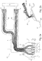
- FIG. 1 shows a schematic plan view of a solution designed according to implantable cuff electrode CE, on its preferably consisting of polyimide carrier substrate 1, in addition to the location-selective detection of neuronal electrical signals and for selective electrical stimulation of individual nerve fibers provided first electrode assembly 2 serving for inhibiting at least one selected nerve fiber second electrode arrangement 7 is applied.
- the second electrode arrangement 7, which extends along the efferent, here to the heart H, leading to signal propagation, comprises two axially spaced second electrode strips 8, between which a second electrode structure 13 is centrally provided which consists of four second electrode surfaces 9 arranged separately from one another.
- All of the electrodes 8, 13 of the second electrode arrangement 2 are connected or connectable to a signal generator 6 'via electrical interconnects L applied to the carrier substrate 1 or integrated therein, which together with the signal detector and generator 6 and with a power source in a separately encapsulated , implantable unit is integrated.
- the electrical interconnects L may optionally have a separable connection structure V.
- the second electrode arrangement 2 comprises optical waveguide arrangements 10, each of which distributes four in the circumferential direction U. arranged, separate optical waveguide openings 11 include.
- the optical waveguides LI to the individual optical waveguide openings or apertures 11 extend within the carrier substrate 1 and can be combined on the proximal side with a uniform light source LQ or with separate light sources LQ different light wavelengths to optogenetically selectively activated stimuli and / or optically activated and selective inhibition along certain To cause nerve fibers.
- the geometric shape and size of the individual electrodes ie, the first and second electrode strips 5, 8 and the first and second electrode surfaces 4, 9 can basically be made individually matched and are particularly based on the diameter of the nerve fiber bundle around which the implantable cuff electrode CF can be applied.
- the extension of the first and second electrode structures and electrode strips oriented in the circumferential direction U and, if appropriate, of the optical waveguide arrangements 10 preferably corresponds to the peripheral edge of the nerve fiber bundle to be wrapped with the cuff electrode CE.
- the axial distance of the tripolar electrode arrangement should preferably be adapted to the diameter and the resulting distance of the so-called Ranvier Schnürringe in myelinated nerve fibers of the nerve fibers to be excited.
- the electrodes are shown as rectangular electrode surfaces. In an advantageous manner, in particular for the purpose of avoiding field line densifications occurring at electrode rectangular edges, it is advisable to form the electrode surfaces at least with rounded corners.
- Electrode strip 5 in about the same length as the axial distance of the rings or slightly larger to choose to reach with sufficiently high statistical probability and the Ranvierschen rings very large fibers. The same applies preferably also to the axial spacing of the second electrode strips 8.
- the total axial extension of the entire cuff electrode CE should be matched to the intracorporeal size ratios of the respective nerve fiber bundles, and typically should not exceed 4 cm.
- the carrier substrate 1 has at least one, preferably two or three openings 14 reinforced by metal ring structures, which serve for fastening the implanted electrode arrangement CF to the nerve fiber bundle.
- the attachment takes place with the aid of a surgical thread which is threaded at least once through the openings 14 and in which the tissue surrounding the nerve fiber bundle is sutured.
- the carrier substrate 1 adjoining the carrier substrate area 1B is in Style of a flat flag laterally from the nerve fiber bundle and protrudes into the surrounding tissue.
- the metal ring structures 14 are intended to help mechanically secure the fastening forces acting along the surgical thread and to prevent drastic damage to the support substrate.
- the second electrode arrangement 7 is placed on the side H leading to the heart along the Nerve fiber bundle to arrange.
- the second, the selective detection and selective stimulation of localized nerve fibers serving electrode assembly 2 is attached along the nerve fiber bundle brain side G.
- the first and second electrode strips 5, 8 and the first and second electrode surfaces 4, 9 are vapor-deposited or sputtered onto the carrier substrate, galvanic amplification is conceivable. Laser structuring of thin metal foils is also possible as a technology.
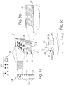
- the electrode strips For permanent joining, in particular of the first and second electrode strips 5, 8 to the carrier substrate 1, the electrode strips have local openings 15, see FIG. 3a through which at least partially the polymer material of the carrier substrate 1 passes or protrudes.
- the electrode surface 16 of each of the first and second electrode strips 5, 8 are otherwise arranged flush with the carrier substrate upper side 1 'and contact the surface of the nerve fiber bundle directly.
- the electrode strips 5, 8 each have a metallic base plate 17, which provides an upper side 18 and a lower side 19. Integrally with the upper side 18 of the base plate 17, orthogonally elevated structural elements 20 are provided over the upper side 18, preferably distributed over the entire upper side, preferably in the form of columnar, ribbed, web or sleeve-like extensions which extend over one of the carrier substrate surface 1 '. facing surface region 21, which can come in direct contact with the epineurium of the nerve fiber bundle.
- an adhesion promoter layer 22 is advantageously provided at least between the underside 19 and the polymer material of the carrier substrate 1 surrounding the base plate 17.
- the adhesion promoter layer 22 can also be applied on the upper side 18.
- Particularly suitable primer layers consist of silicon carbide (SiC) and diamond like Carbon (DLC).
- the electrode strips 5, 8 are made of iridium oxide, which is one of the materials with one of the highest charge transfer capacities.
- FIG Figure 3c shows the longitudinal section through a structural element 20 having an orthogonal to the top 18 of the metallic base plate 17 oriented longitudinal extent LA, along which the structural element 20 at least a second surface portion 23 provides, which is oriented parallel to the top 18 of the metallic base plate 17 and on which Adhesive layer 22 or a bonding agent layer assembly 22 'is applied.
- the second surface region 23 is spaced from the first surface region 18 and completely surrounded by the biocompatible polymer separated by the adhesion promoter layer (22) and the adhesion promoter layer arrangement (22 ').
- the second surface area is as from the Figure 3c can be seen, the upper side 18 of the base plate 17 facing oriented.
- the number and arrangement of the individual structural elements 20 can be chosen arbitrarily, but are preferably geometrically ordered constellations KO, such as. Square, pentagonal, hexagonal or higher order arrangement pattern, as is known from FIG. 3b can be seen.
- geometrically ordered constellations KO such as. Square, pentagonal, hexagonal or higher order arrangement pattern, as is known from FIG. 3b can be seen.
- the base plate 17 is located centrally within the carrier substrate 1, ie the thickness of the biocompatible polymer layer adjacent to the underside 19 of the base plate 17 should be approximately the thickness of the upper surface 18 of the base plate 17 adjacent polymer layer correspond.
- Base plate 17 is associated with the experimentally demonstrable advantage that compensate for the material inherent stresses acting on the base plate 17, which form during an annealing process. The annealing process is required to impress a bias of material into the carrier substrate, through which the implantable sleeve electrode is able to independently wind around the nerve fiber bundle.
- a cuff M which partially encloses the carrier substrate 1 of the implantable cuff electrode CE is shown, which comprises that region of the carrier substrate 1 both on its lower and upper side which adjoins directly to the carrier substrate region 1B and, unlike the carrier substrate region 1B, does not extend in the way of a material-inherent mechanical bias voltage is deformed straight cylindrical shape and brought in this way flush with the epineurium of the nerve fiber bundle in the implanted state in conditioning.
- the sleeve M serves primarily for improved handling of the implantable sleeve electrode CE, which requires particularly careful handling by the surgeon on account of its very low carrier substrate thickness and the filigree electrode arrangements applied to the carrier substrate surface.
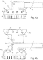
- the sleeve M is preferably formed in one piece and has a sleeve lower part Mu and a sleeve upper part Mo, both of which are hingedly connected via a living hinge hinge 25, see FIGS. 4b and 4c ,
- the sleeve bottom part Mu has a recess 26 embedding the carrier substrate 1 into which the carrier substrate 1 can be inserted.
- the lower sleeve part Mu comprises the carrier substrate 1 in the FIG. 4b removable, framing manner, that is, the lower sleeve part MU protrudes laterally below the carrier substrate 1.
- the sleeve upper part Mo which is connected in one piece to the lower sleeve part Mu via the hinge joint 25, is adapted in shape and size to the lower sleeve part Mu and also has the same shape as the one Cuff bottom part Mu on a the carrier substrate 1 embedding recess 27, so that in the closed state of the sleeve M, the carrier substrate 1 in the in FIG. 4a hermetically, wherein only the carrier substrate region 1B protrudes from the sleeve M.
- the cuff M also serves in particular for improved fixation of the cuff electrode CE relative to the nerve fiber bundle.
- the sleeve upper and lower sides Mo, Mu each provide attachment openings 14 ', see Fig. 4a, b . d , which are congruent with the introduced within the support substrate 1 mounting holes 14 in the collapsed state of the sleeve M are. In this way it is possible to guide a surgical suture 28 through the apertures 14, 14 'of the cuff electrode CE encompassed by the cuff M. In this way, the metal ring encased mounting opening 14 of the sleeve electrode CE can be relieved by the introduced within the sleeve M mounting opening 14 '.
- the sleeve M is made of a stable plastic material, for example of parylene.
- the Mo and Mu can also consist of a polymer hybrid (eg, parylene (inside) and silicone rubber outside). This hybrid has the advantage that the stability of the parylene is combined with the tear strength of the silicone.
- the attachment openings 14 'inside the sleeve M are made reinforced by appropriate material thickening.
- opening windows 29 are introduced, which ensure free access to the reference electrode surfaces 12.
- a cross-section through this is represented by the carrier substrate 1 encompassed by the sleeve M, on the upper side of which reference electrode surfaces 12 are introduced, which remain freely accessible through the opening windows 29 introduced inside the sleeve upper part Mo.
- the opening windows 29 include the reference electrode surfaces 12 with a sloping boundary edge 29 ', so that it is ensured that the Reference electrode surfaces 29 can come into body contact with the surrounding tissue over the entire surface.
- interlocking structures V are arranged between the cuff top and bottom parts Mo, Mu, which consist, for example, of a pin 30 and a recess 31 arranged opposite one another, see FIGS. 4c and f.
- the pins 30 are subjected to force in the corresponding recess 31, in which the pin 31 is held by friction, permanently.
- FIG. 4f the closed state of a locking structure V is illustrated.
- the pin 30 mounted on the sleeve top Mo protrudes through a corresponding opening introduced in the carrier substrate 1 and terminates at the end within the recess 31 of the sleeve base Mu.
- alternative embodiments for the locking structures are conceivable, for example in the form of suitably designed locking mechanisms.
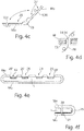
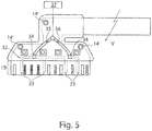
- FIG. 5 another embodiment is illustrated, which facilitates facilitated implantation of the solution formed according to the sleeve electrode CE.
- a fluid channel system 32 is incorporated, which is completely covered by the carrier substrate 1.
- the fluid channel system 32 extends substantially in the region of the carrier substrate region 1B, which assumes the shape of a graduated cylinder due to a material-inherent bias without external force by means of an autonomous self-winding. If, on the other hand, the fluid channel system 32 is filled with a fluid, preferably water, then the water pressure forming along the fluid channel system 32 can just clamp the carrier substrate region 1b against the material-inherent winding forces.
- the fluid channel system 32 has in the circumferential direction of the lateral surface of the self-forming graduated cylinder extending fluid channel branches 33, which force the required extension of the carrier substrate area 1B in the filled state.
- At least two channel openings 34 are provided within the carrier substrate 1, whose size and arrangement are dimensioned such that they fluid-tight at inlet and outlet openings of extending within the sleeve M Fluidzu- or discharges 35, 36 open.
- the inlet and outlet lines 35, 36 running inside the cuff M are fluidically connected to a fluid control system 37, which can be actuated by an operator.
- the fluid channel system 32 is filled with a fluid, whereby the carrier substrate region 1B is stretched.
- the surgeon places the cuff electrode CE exactly at a predetermined position along the nerve bundle.
- the emptying of the fluid channel system 32 is performed by the surgeon, whereby the carrier substrate area 1B automatically wraps around the nerve fiber bundle.
- the cuff electrode CE is fixed to the surrounding tissue with a suture thread through the attachment holes 14 'provided in the cuff.
- the channel openings 34 are provided with metallized contacts, via which an electrical voltage along the leads 35, 36 for deployment of the implantable electrode assembly CE via a correspondingly modified controller 37 can be applied until the electrode is finally placed.
Landscapes
- Health & Medical Sciences (AREA)
- Life Sciences & Earth Sciences (AREA)
- Veterinary Medicine (AREA)
- Public Health (AREA)
- General Health & Medical Sciences (AREA)
- Animal Behavior & Ethology (AREA)
- Engineering & Computer Science (AREA)
- Biomedical Technology (AREA)
- Heart & Thoracic Surgery (AREA)
- Neurology (AREA)
- Radiology & Medical Imaging (AREA)
- Nuclear Medicine, Radiotherapy & Molecular Imaging (AREA)
- Neurosurgery (AREA)
- Cardiology (AREA)
- Orthopedic Medicine & Surgery (AREA)
- Physics & Mathematics (AREA)
- Biophysics (AREA)
- Pathology (AREA)
- Medical Informatics (AREA)
- Molecular Biology (AREA)
- Surgery (AREA)
- Electrotherapy Devices (AREA)
Description
Die Erfindung bezieht sich auf eine implantierbare Elektrodenanordnung zur ortsselektiven Erfassung neuronaler elektrischer Signale, die sich längs wenigstens einer in einem Nervenfaserbündel enthaltenden Nervenfaser ausbreiten, sowie zur selektiven elektrischen Stimulation der wenigstens einen selektierten Nervenfaser, mit einem biokompatiblen Trägersubstrat, das zumindest einen Trägersubstratbereich aufweist, der um das Nervenfaserbündel manschettenartig anlegbar ist und eine im implantierten Zustand dem Nervenfaserbündel zugewandt orientierte, geradzylinderförmige Trägersubstratoberfläche aufweist, die eine axiale sowie eine in Umfangsrichtung orientierte Erstreckung besitzt und an der eine erste Elektrodenanordnung angebracht ist. Die erste Elektrodenanordnung umfasst in axialer Abfolge jeweils voneinander beabstandet wenigstens drei erste Elektrodenstrukturen mit jeweils wenigstens zwei in Umfangsrichtung verteilt angeordneten ersten Elektrodenflächen, sowie wenigstens zwei axial zueinander beabstandete, sich in Umfangsrichtung erstreckende und jeweils eine Ringform annehmende, erste Elektrodenstreifen, die die wenigstens drei Elektrodenstrukturen axial beidseitig einschließen. Die erste Elektrodenanordnung ist mit einem Signaldetektor und -generator verbindbar, d.h. die Elektrodenanordnung ist über eine trennbare elektrische Schnittstelle, bspw. in Form einer Steckereinheit mit dem Signaldetektor und -generator verbunden, oder direkt, d.h. untrennbar verbunden.The invention relates to an implantable electrode arrangement for the location-selective detection of neuronal electrical signals which propagate along at least one nerve fiber contained in a nerve fiber bundle and for the selective electrical stimulation of the at least one selected nerve fiber, with a biocompatible carrier substrate having at least one carrier substrate region around the nerve fiber bundle is cuff-like applied and a in the implanted state the nerve fiber bundle facing oriented, straight cylindrical carrier substrate surface having an axial and a circumferentially oriented extent and to which a first electrode assembly is mounted. The first electrode arrangement comprises, in axial sequence, at least three first electrode structures spaced apart from one another, each having at least two first electrode surfaces distributed in the circumferential direction, and at least two axially relative to one another spaced, circumferentially extending and each receiving a ring shape, first electrode strips which enclose the at least three electrode structures axially on both sides. The first electrode arrangement can be connected to a signal detector and generator, ie the electrode arrangement is connected via a separable electrical interface, for example in the form of a plug unit to the signal detector and generator, or directly, ie inseparably connected.
Die arterielle Hypertonie ist eine weltweit verbreitete, typische Zivilisationskrankheit, die das Leben von Millionen Patienten bedroht und gleichzeitig im hohen Maße die Gesundheitssysteme belastet. Bisher bekannte therapeutische Maßnahmen gründen auf der Verabreichung blutdrucksenkender Arzneimittel, wie bspw. ACE-Hemmer, Betablocker etc., diese weisen jedoch neben der erwünschten blutdrucksenkenden Wirkung beachtliche Nebenwirkungen auf, wie bspw. Bradykardie, Herzinsuffizienz, Asthmaanfälle etc. auf. Hinzukommt, dass trotz der Entwicklung neuer blutdrucksenkender Medikamente bei bis zu 30% aller Patienten bei entsprechender Medikation kein adäquater Zielblutdruck erreicht werden kann, siehe Beitrag von
Einen anderen therapeutischen Ansatz zur Begegnung von Bluthochdruck verfolgt eine Studie seitens der Anmelderin, die in dem Artikel von
Das Konzept der selektiven Vagusnervstimulation stützt sich auf Erfahrungen der seit vielen Jahren angewandten und etablierten neuromodulatorischen Therapie schwerer Formen der Epilepsie, bei der der Vagusnerv mit Hilfe einer implantierten Elektrodenanordnung gesamtheitlich elektrisch stimuliert wird, um bei sich anbahnenden epileptischen Anfällen zumindest deren Ausmaß in Hinblick auf Stärke und zeitliche Dauer abzumildern, siehe hierzu
Im Gegensatz dazu gilt es zur chronischen Behandlung von Hypertonie die blutdruckrelevanten Fasern messtechnisch zunächst zu lokalisieren um sie anschließend in geeigneter Weise selektiv elektrisch zu stimulieren. Um den Vagusnerv durch die implantive Maßnahme der Applikation einer Elektrodenanordnung möglichst zu schonen und das Epineurium des Vagusnervs möglichst nicht zu irritieren, wird in dem zitierten Beitrag von Dennis T. T. Plachta et al. der Einsatz einer sog. Cuff-Elektrode vorgeschlagen, die extraneural am Vagusnerv anbringbar ist. Dies hat den Vorteil einer relativ leichten Positionierung der Cuff-Elektrode längs des Vagusnerves und ermöglicht darüber hinaus einen geringfügig invasiv und daher schonend und schnell durchzuführenden chirurgischen Eingriff am Patienten.In contrast, for the chronic treatment of hypertension, the blood pressure-relevant fibers first have to be localized in order to then selectively selectively stimulate them electrically. In order to protect the vagus nerve as much as possible by the implantation of the application of an electrode assembly and not to irritate the epineurium of the vagus nerve as possible, is in the cited article by Dennis T. T. Plachta et al. proposed the use of a so-called. Cuff electrode which is extraneurally attachable to the vagus nerve. This has the advantage of a relatively easy positioning of the cuff electrode along the vagus nerve and also allows a slightly invasive and therefore gentle and easy to perform surgical intervention on the patient.
Für die natürliche Blutdruckregelung dient der Baroreflex, der einen homöostatischen, selbstregulierenden Mechanismus darstellt und bei einem erhöhten Blutdruck reflektorisch unterschiedliche Effektoren aktiviert. U.a. wird hierbei die Herzfrequenz abgesenkt, aber auch die arteriellen Gefäße werden geweitet, um damit den Blutdruck zu senken. Im Falle eines niedrigen Blutdruckes wird der Baroreflex unterdrückt, wodurch die Herzfrequenz steigt und Blutgefäße verengt werden damit der Blutdruck wieder steigt. Die sensorischen Eingänge für den Baroreflex stellen sog. Barorezeptoren dar, die sich unter anderem in den Wänden des Aortenbogens befinden. Von dort ziehen die Blutdruckinformationen monosynaptisch längs der blutdruckrelevanten Nervenfasern, im Folgenden als barorezeptive Fasern bezeichnet, in den Hirnstamm. Beim Überschreiten eines Schwellenwertes für den Blutdruck löst der Baroreflex eine Inhibition sympathischer Nervenfasern aus, was zu einer unmittelbaren Absenkung des Blutdruckes führt. Mit Hilfe der unter Bezugnahme auf
Die Manschettenelektrode CE besteht aus einem flexiblen, biokompatiblen Trägersubstrat 1, das in der realisierten Ausführungsform eine ca. 11 µm dicke Polyimid-Folie ist, an deren der Zeichenebene in
Sowohl zur ortsselektiven Erfassung neuronaler elektrischer Signale als auch zur selektiven elektrischen Stimulation wenigstens einer Nervenfaser NF dienen drei axial jeweils gleich zueinander beabstandet angeordnete, erste Elektrodenstrukturen 3, die in Umfangsrichtung U wenigstens zwei, im illustrierten Ausführungsbeispiel gemäß
Die Dreifach- bzw. Tripol-Anordnung der jeweils ersten Elektrodenstrukturen 3, über deren jeweils erste Elektrodenflächen 4 monopolar neuronale elektrische Signale erfasst bzw. elektrische Signale zu Zwecken der ortsselektiven Stimulation abgegeben werden können, ermöglicht es Impedanzänderungen aufgrund von Gewebewachstum an den metallischen Elektrodenflächen 4 festzustellen und auswertetechnisch zu eliminieren, zum anderen können blutdruckrelevante neuronale Signale, die mit einem leichten zeitlichen Versatz durch die Tripolanordnung axial längs einer entsprechenden Nervenfaser NF laufen, mittels geeigneter tripolarer Verstärkung detektiert werden. Neben den vorstehend bezeichneten ersten Elektrodenstrukturen 3 sowie ersten, jeweils eine Ringform annehmenden Elektrodenstreifen 5, die allesamt an der in
Mit der bekannten implantierbaren Elektrodenanordnung konnte im Rahmen von Tierversuchen an Ratten gezeigt werden, dass mit Hilfe der gleichverteilt um das Nervenfaserbündel NFB tripolar angeordneten, insgesamt 24 ersten Elektrodenflächen Blutdruck korrelierte, neuronale elektrische Zeitsignale, im Folgenden als barorezeptive Signale bezeichnet, erfasst werden können, die darüber hinaus hinsichtlich ihrer in Umfangsrichtung abhängigen Signalpegel zur Ortung der barorezeptiven Nervenfasern dienen. Die Stimulation erfolgte tripolar jeweils mit jener Elektrodenfläche 4 oder jenen Elektrodenflächen 4 der mittig angeordneten ersten Elektrodenstruktur 3 der Tripol-Anordnung, über die bei der Detektion der jeweils größte Signalpegel unter den barorezeptiven Signalen erfasst wurde. Es konnte gezeigt werden, dass durch selektive Stimulation barorezeptiver Nervenfasern der Blutdruck zuverlässig deutlich gesenkt werden kann, wobei sich lediglich eine sehr schwache Bradykardie (Pulsreduzierung unter 60 Schläge pro Minute) sowie eine kaum nennenswerte Bradypnoe (Reduzierung der Atmung unter 20 Atemzüge pro Minute) einstellten.With the known implantable electrode arrangement could be shown in animal experiments on rats that with the help of equally distributed around the nerve fiber bundle NFB tripolar arranged a total of 24 first electrode surfaces blood pressure correlated, neuronal electrical time signals, hereinafter referred to as baroreceptive signals, can be detected moreover, with respect to their circumferentially dependent signal levels to locate the baroreceptive nerve fibers. The stimulation was tripolar in each case with that
Zur selektiven elektrischen Stimulation der barorezeptiven Nervenfasern wurden elektrische Stimulationssignale mit einer Stimulationsfrequenz jeweils zwischen 30 bis 50 Hz, einer Stimulationsdauer von 0,1 bis 0,5 msec sowie einer Stimulationsamplitude von 0,4 bis 1,5 mA an die jeweils selektierten Elektrodenflächen 4 der mittig angeordneten Elektrodenstruktur appliziert. Hierbei erfolgte die elektrische Stimulation längs der barorezeptiven Nervenfasern isotrop, d. h. ohne Vorgabe einer festgelegten Signalausbreitungsrichtung, so dass sich die elektrischen Stimulationssignale sowohl längs afferenter sowie auch efferenter Nervenfasern ausbreiten konnten. Letztere können einen direkten, unkontrollierten Einfluss auf die Herzaktivität ausüben, was zu unerwünschten Nebenwirkungen führen kann, insbesondere bei im Vergleich zu Ratten größeren Lebewesen.For selective electrical stimulation of the baroreceptive nerve fibers electrical stimulation signals with a stimulation frequency in each case between 30 to 50 Hz, a stimulation time of 0.1 to 0.5 msec and a stimulation amplitude of 0.4 to 1.5 mA to each selected
Der Erfindung liegt die Aufgabe zugrunde eine implantierbare Elektrodenanordnung der vorstehend bezeichneten Art zur ortsselektiven Erfassung neuronaler elektrischer Signale, die sich längs wenigstens einer in einem Nervenfaserbündel enthaltenen Nervenfasern ausweiten, sowie zur selektiven elektrischen Stimulation wenigstens einer Nervenfaser mit den Merkmalen des Oberbegriffes des Anspruches 1 derart weiterzubilden, so dass Vorkehrungen getroffen werden sollen, mögliche Nebenwirkungen bedingt durch unkontrollierte Signalausbreitungseffekte der längs in barorezeptiven Nervenfasern selektiv eingekoppelten, elektrischen Stimulationssignale möglichst vollständig auszuschließen. Insbesondere gilt es Vorkehrungen zu treffen eine Ausbreitung von elektrischen Stimulationssignalen längs efferenter Nervenfasern zu unterbinden ohne dabei einen signifikant nachhaltigen Einfluss auf nicht barorezeptive, afferente sowie efferente Nervenfasern innerhalb des Nervenfaserbündels auszuüben.The invention has for its object an implantable electrode assembly of the type described above for the location-selective detection of neuronal electrical signals that extend along at least one contained in a nerve fiber bundle nerve fibers, as well as for selective electrical stimulation of at least one nerve fiber with the features of the preamble of
Die Lösung der der Erfindung zugrunde liegenden Aufgabe ist im Anspruch 1 angegeben. Den Lösungsgedanken in vorteilhafter Weiser weiterbildende Merkmale sind Gegenstand der Unteransprüche sowie der weiteren Beschreibung unter Bezugnahme auf die Ausführungsbeispiele zu entnehmen.The solution of the problem underlying the invention is specified in
Die lösungsgemäße implantierbare Elektrodenanordnung gemäß den Merkmalen des Oberbegriffes Anspruches 1 zeichnet sich dadurch aus, dass in axialer Abfolge auf der dem Nervenfaserbündel zugewandten geradzylinderförmigen Trägersubstratoberfläche axial neben der ersten Elektrodenanordnung wenigstens eine zweite Elektrodenanordnung angeordnet ist, die wenigstens zwei axial voneinander beabstandete, sich in Umfangsrichtung erstreckende und jeweils eine Ringform annehmende zweite Elektrodenstreifen sowie axial zwischen den wenigstens zwei zweiten Elektrodenstreifen wenigstens eine jeweils wenigstens zwei in Umfangsrichtung gleich verteilt angeordnete zweite Elektrodenflächen umfassende zweite Elektrodenstruktur umfasst, wobei die zweite Elektrodenanordnung zumindest mit dem Signalgenerator oder einem weiteren Signalgenerator verbunden ist.The implantable electrode arrangement according to the invention in accordance with the features of the preamble of
Die eingangs erläuterte als Manschettenelektrode ausgebildete, implantierbare Elektrodenanordnung, wie sie unter Bezugnahme auf die
Die ebenso auf dem gleichen, einstückig zusammenhängend ausgebildeten Trägersubstrat an der gleichen Trägersubstratoberfläche, wie die erste Elektrodenanordnung aufgebrachte zweite Elektrodenanordnung steht in einer räumlich festen Zuordnung zur ersten Elektrodenanordnung, insbesondere zu den ersten Elektrodenflächen der wenigstens drei ersten Elektrodenstrukturen, mit deren Hilfe barorezeptive Nervenfasern innerhalb des Nervenfaserbündels ortsselektiv erfasst und darüber hinaus selektiv elektrisch stimulierbar sind. In Kenntnis der lokalisierten barorezeptiven Nervenfasern lässt sich die zweite Elektrodenanordnung zu Zwecken einer selektiven Inhibition der barorezeptiven Nervenfasern zur Unterdrückung einer Weiterleitung elektrischer Stimulationssignale längs efferenter, d.h. zum Herzen führender Nervenfasern nutzen. Hierzu dienen wenigstens zwei, vorzugsweise vier oder mehr zweite Elektrodenflächen wenigstens einer zweiten Elektrodenstruktur, die gleichfalls wie die ersten Elektrodenflächen einer der wenigstens drei ersten Elektrodenstrukturen in Umfangsrichtung der dem Nervenfaserbündel zugewandt orientierten, sich geradzylinderförmig ausbildenden Trägersubstratoberfläche gleich verteilt angeordnet sind. Zu Zwecken der Inhibition lokalisierter efferenter barorezeptiver Nervenfasern wird wenigstens eine der zweiten Elektrodenflächen der zweiten Elektrodenstruktur elektrisch aktiviert, wodurch es zu einer gezielt, zeitlich begrenzten, selektiven Inhibition der betreffenden efferenten Nervenfaser kommt. Hierbei tritt von der jeweils wenigstens einen aktivierten, zweiten Elektrodenfläche ein elektrisches Polarisationsfeld in das Nervenfaserbündel ein und wechselwirkt vornehmlich mit der zu inhibieren Nervenfaser. Um das sich während der Inhibition in das Nervenfaserbündel ausbreitende elektrische Polarisationsfeld axial zu begrenzen, dienen jeweils zur zweiten Elektrodenstruktur axial beidseitig angebrachte zweite Elektrodenstreifen, die im implantierten Zustand der Manschettenelektrode das Nervenfaserbündel vollständig umschließende Ringelektroden darstellen.The second electrode arrangement likewise applied to the same, integrally connected carrier substrate on the same carrier substrate surface as the first electrode arrangement is spatially fixed to the first electrode arrangement, in particular to the first electrode surfaces of the at least three first electrode structures, with the aid of which baroreceptive nerve fibers within the Nerve fiber bundles are detected site selective and beyond selectively electrically stimulated. Knowing the localized baroreceptive nerve fibers, the second electrode assembly may be longitudinally efferent for purposes of selectively inhibiting the baroreceptive nerve fibers to suppress transmission of electrical stimulation signals. ie use to the heart of leading nerve fibers. At least two, preferably four or more, second electrode surfaces of at least one second electrode structure are used for this purpose. Like the first electrode surfaces of one of the at least three first electrode structures, they are equally distributed in the circumferential direction of the carrier layer surface facing the nerve fiber bundle. For purposes of inhibiting localized efferent baroceptive nerve fibers, at least one of the second electrode surfaces of the second electrode structure is electrically activated, thereby providing selective, timed, selective inhibition of the respective efferent nerve fiber. In this case, an electric polarization field enters the nerve fiber bundle from the respectively at least one activated, second electrode surface and interacts primarily with the nerve fiber to be inhibited. In order to axially delimit the electric polarization field propagating into the nerve fiber bundle during the inhibition, second electrode strips are provided axially on both sides of the second electrode structure and represent ring electrodes completely enclosing the nerve fiber bundle in the implanted state of the cuff electrode.
Zu Zwecken der Inhibition ausgewählt efferenter Nervenfasern ist die lösungsgemäß ausgebildete, implantierbare Elektrodenanordnung derart an das Nervenfaserbündel zu applizieren, so dass die lösungsgemäß vorgesehene zweite Elektrodenanordnung dem Herzen, bzw. den barorezeptiven Rezeptoren zugewandt, d.h. caudal, und die erste Elektrodenanordnung, mit der die selektive Erfassung neuronaler elektrischer Signale sowie auch die elektrische Stimulation lokalisierter Nervenfasern vorgenommen wird, dem Gehirn, d.h. rostral, längs des Nervenfaserbündels zugewandt orientiert sind.For the purpose of inhibiting selected efferent nerve fibers, the implantable electrode arrangement designed in accordance with the invention is to be applied to the nerve fiber bundle such that the second electrode arrangement provided according to the invention faces the heart or the baroreceptive receptors, i. caudally, and the first electrode arrangement, which makes selective detection of neuronal electrical signals, as well as the electrical stimulation of localized nerve fibers, to the brain, i. rostral, oriented along the nerve fiber bundle.
Mit Hilfe der zweiten Elektrodenanordnung lässt sich die Inhibition entweder im Wege eines sog. anodalen Blockes oder durch Applikation von sinusförmigen Signalen von Frequenzen im Kilohertzbereich realisieren. Im Falle des anodalen Blocks wird wenigstens eine der zweiten Elektrodenflächen anodisch polarisiert, wodurch ein am Ort der efferenten Nervenfaser vorherrschendes Spannungspotential erzeugt wird, durch das eine aktivierende Stimulation der entsprechenden Nervenfaser unterdrückt wird. Ebenso kann eine Inhibition im Wege einer Hochfrequenzsignalapplikation erzielt werden, bei der an wenigstens einer ausgewählten zweiten Elektrodenfläche ein hochfrequentes elektrisches Inhibitionssignal angelegt wird, wodurch die elektrischen Signalübertragungsmechanismen längs der efferenten Nervenfasern kurzzeitig zum Erliegen kommen.With the aid of the second electrode arrangement, the inhibition can be realized either by means of a so-called anodal block or by application of sinusoidal signals of frequencies in the kilohertz range. In the case of the anodal block, at least one of the second electrode surfaces is anodically polarized, thereby producing a voltage potential prevailing at the location of the efferent nerve fiber, by which an activating stimulation of the corresponding nerve fiber is suppressed. Likewise, an inhibition can be achieved by means of a high-frequency signal application in which a high-frequency electrical inhibition signal is applied to at least one selected second electrode surface, whereby the electrical signal transmission mechanisms come to a halt briefly along the efferent nerve fibers.
In beiden Fällen wirkt die lösungsgemäß vorgesehene zweite Elektrodenanordnung aufgrund ihrer räumlich axialen Begrenztheit, die durch den axialen Abstand beider zweiten Elektrodenstreifen gegeben ist, trotz ihrer räumlichen Nähe zur ersten Elektrodenstruktur, immerhin sollte die implantierbare Elektrodenanordnung eine axiale Länge von 4 cm nicht überschreiten, axial räumlich begrenzt längs der zu inhibierenden efferenten Nervenfasern, so dass die gehirnseitig längs des Nervenfaserbündels angeordnete erste Elektrodenanordnung in den jeweils lokalisierten afferenten Nervenfasern zum Gehirn führende elektrische Stimulationssignale unbeeinflusst von dem Inhibitionsmechanismus einkoppeln kann. Auf diese Weise können jegliche Nebenwirkungen, bedingt durch mögliche direkte Stimulationen in Richtung der zum Herz führenden, d.h. efferenten Nervenfasern ausgeschlossen werden.In both cases, the solution provided according to the second electrode arrangement acts due to their spatial axial limitation, which is given by the axial distance of the two second electrode strips, despite their proximity to the first electrode structure, after all, the implantable electrode assembly should not exceed an axial length of 4 cm, axially spaced bounded along the efferent nerve fibers to be inhibited, so that the first electrode arrangement arranged on the brain side along the nerve fiber bundle can couple in the respectively localized afferent nerve fibers to the brain leading electrical stimulation signals uninfluenced by the inhibition mechanism. In this way, any side effects due to possible direct stimulations towards the heart, i. efferent nerve fibers are excluded.
In vorteilhafter Weise sind die zweiten Elektrodenflächen der zweiten Elektrodenstruktur im implantierten Zustand der Manschettenelektrode längs einer virtuellen Kreislinie gleich verteilt angeordnet, um auf diese Weise relativ zum Umfangsrand eines Nervenfaserbündels lokalisierte efferente Nervenfasern selektiv und effektiv zu inhibieren.Advantageously, in the implanted state of the cuff electrode, the second electrode surfaces of the second electrode structure are equally distributed along a virtual circular line in order to selectively and effectively inhibit localized efferent nerve fibers relative to the peripheral edge of a nerve fiber bundle.
Nicht notwendigerweise jedoch in vorteilhafter Form sind die zweiten Elektrodenflächen in Form und Größe identisch untereinander ausgebildet, wobei ihre axialen Erstreckungen jeweils identisch gewählt sind, gleichsam den axialen Erstreckungen der ersten Elektrodenflächen der ersten drei Elektrodenstrukturen. Die in Umfangsrichtung orientierte Erstreckung der jeweils zweiten Elektrodenflächen ist größer gewählt als die in Umfangsrichtung orientierte Erstreckung der ersten Elektrodenflächen. Somit weisen die zweiten Elektrodenflächen gegenüber den ersten Elektrodenflächen vorzugsweise ein größeres Flächenmaß auf, wodurch die Ortsselektivität, mit der die zweiten Elektrodenflächen bestimmte efferente Nervenfasern elektrisch zu polarisieren vermögen geringer ist als die Ortsselektivität, mit der die ersten Elektrodenflächen lokalisierte Nervenfasern elektrisch zu stimulieren vermögen. Alternativ können die zweiten Elektrodenflächen anstelle einer Rechtecksform auch als Kreisflächen ausgebildet sein. Dies hat den Vorteil, dass sich keine lokalen, durch Kanten oder Ecken bedingten elektrische Potenzialfeldspitzen ausbilden.Not necessarily, however, in an advantageous form, the second electrode surfaces are identical in shape and size with each other, their axial extensions are each selected identically, as the axial extensions of the first electrode surfaces of the first three electrode structures. The circumferentially oriented extension of the respectively second electrode surfaces is chosen larger than the circumferentially oriented extension of the first Electrode surfaces. Thus, the second electrode surfaces preferably have a larger areal dimension than the first electrode surfaces, whereby the spatial selectivity with which the second electrode surfaces are able to electrically polarize certain efferent nerve fibers is less than the spatial selectivity with which the first electrode surfaces are able to electrically stimulate localized nerve fibers. Alternatively, instead of a rectangular shape, the second electrode surfaces can also be designed as circular surfaces. This has the advantage that no local, caused by edges or corners electric potential field peaks form.
Die zweite Elektrodenanordnung ist vorzugsweise in Form einer Tripolar-Elektrodenanordnung ausgebildet, d. h. die zweite Elektrodenstruktur ist axial beidseitig von jeweils einem ringförmig ausgebildeten zweiten Elektrodenstreifen begrenzt, wobei der axiale Abstand zwischen beiden zweiten Elektrodenstreifen längs des Trägersubstrates vorzugsweise zwischen 0,5 cm und 3 cm, insbesondere zwischen 0,75 cm und 1,25 cm gewählt ist. Die ringförmig ausgebildeten zweiten Elektrodenstreifen besitzen vorzugsweise eine axiale Erstreckung zwischen 1µm und 5 mm, vorzugsweise zwischen 100 µm und 4000 µm.The second electrode arrangement is preferably designed in the form of a tripolar electrode arrangement, i. H. the second electrode structure is delimited axially on both sides by a respective annular second electrode strip, wherein the axial distance between the two second electrode strips along the carrier substrate is preferably selected between 0.5 cm and 3 cm, in particular between 0.75 cm and 1.25 cm. The ring-shaped second electrode strips preferably have an axial extent of between 1 μm and 5 mm, preferably between 100 μm and 4000 μm.
Die zweiten Elektrodenflächen der zweiten Elektrodenstruktur sind axial mittig zwischen beiden zweiten Elektrodenstreifen angeordnet und verfügen über eine axiale Erstreckung, so dass der jeweils axiale Abstand zu den zweiten Elektrodenstreifen größer ist als ihre eigene axiale Erstreckung.The second electrode surfaces of the second electrode structure are arranged axially centrally between the two second electrode strips and have an axial extension, so that the respective axial distance to the second electrode strips is greater than their own axial extension.
Insbesondere im Hinblick auf die Möglichkeit der Durchführung von depolarisierenden Maßnahmen ist es denkbar, anstelle einer zweiten Elektrodenstruktur drei axial beabstandete zweite Elektrodenstrukturen zwischen den zweiten Elektrodenstreifen anzuordnen, gleichsam zur Ausbildung der jeweils ersten Elektrodenstruktur innerhalb der ersten Elektrodenanordnung. Nur der Vollständigkeit halber sei erwähnt, dass es ebenso denkbar wäre, auch mehr als drei erste und zweite Elektrodenstrukturen zwischen den jeweiligen ersten und zweiten Elektrodenstreifen anzuordnen. So könnten drei, fünf, sieben oder mehr ungeradzahlige erste und/oder zweite Elektrodenstrukturen vorgesehen werden.In particular, with regard to the possibility of carrying out depolarizing measures, it is conceivable, instead of a second electrode structure, to arrange three axially spaced second electrode structures between the second electrode strips, as it were to form the respective first electrode structure within the first electrode arrangement. Only for the sake of completeness it should be mentioned that it would also be conceivable to have more than three first and second electrode structures between the respective first and second To arrange electrode strips. Thus, three, five, seven or more odd-numbered first and / or second electrode structures could be provided.
In einem nachstehend illustrierten bevorzugten Ausführungsbeispiel umfasst eine zweite Elektrodenstruktur vier zweite Elektrodenflächen, deren Elektrodenflächenmaß jeweils kleiner als ein Viertel der Flächengröße jeweils eines zweiten Elektrodenstreifens gewählt ist. Da die sowohl in der ersten als auch in der zweiten Elektrodenanordnung vorgesehenen ersten bzw. zweiten Elektrodenstreifen jeweils als Masse- oder Gegenpole zur Polarisierung der jeweils ersten bzw. zweiten Elektrodenstruktur dienen, sind aus Gründen ladungssymmetrischer Verhältnisse die Flächengrößen der ersten und zweiten Elektrodenstreifen jeweils identisch gewählt. Vorstellbar ist jedoch auch eine individuell unabhängige Flächengrößenwahl in der Ausbildung der ersten und zweiten Elektrodenstreifen.In a preferred embodiment illustrated below, a second electrode structure comprises four second electrode surfaces whose electrode surface dimension is in each case selected to be smaller than a quarter of the surface size of a respective second electrode strip. Since the first and second electrode strips provided in both the first and in the second electrode arrangement serve as ground poles or counter poles for polarizing the respectively first and second electrode structure, the surface sizes of the first and second electrode strips are each selected to be identical for reasons of charge-symmetrical relationships , However, an individually independent area size selection in the design of the first and second electrode strips is also conceivable.
Ferner hat es sich als vorteilhaft erwiesen, sämtliche Elektroden der zweiten Elektrodenanordnung, d.h. die zweiten Elektrodenflächen und zweiten Elektrodenstreifen, aus einem elektrisch leitenden Material zu fertigen, das über eine geringere Ladungsübertragungskapazität verfügt, als das Elektrodenmaterial, aus dem die ersten Elektrodenflächen der ersten Elektrodenanordnung bestehen. Als besonders geeignetes Material mit einer besonders hohen Ladungsübertragungskapazität wird Iridium-Oxid zur Ausbildung der jeweils ersten Elektrodenflächen der ersten Elektrodenanordnung verwendet, wohingegen das Material der zweiten Elektrodenflächen und zweiten Elektrodenstreifen aus Platin oder aus einem elektrisch leitfähigen Polymer besteht.Furthermore, it has been found to be advantageous to use all the electrodes of the second electrode arrangement, i. the second electrode surfaces and second electrode strips to be made of an electrically conductive material having a lower charge transfer capacity, as the electrode material, of which consist of the first electrode surfaces of the first electrode assembly. As a particularly suitable material with a particularly high charge transfer capacity iridium oxide is used to form the respective first electrode surfaces of the first electrode assembly, whereas the material of the second electrode surfaces and second electrode strips consists of platinum or of an electrically conductive polymer.
Sämtliche Elektrodenflächen sowohl der ersten als auch zweiten Elektrodenanordnung sind vorzugsweise bündig zur Trägersubstratoberfläche des Trägersubstrats ausgebildet oder gegenüber dieser abgesetzt angeordnet, so dass sie die Trägersubstratoberfläche nicht überragen, um einen möglichst schonenden Oberflächenkontakt zum Epineurium des Nervenfaserbündels herzustellen. Durch den nichtinvasiven Oberflächenkontakt kann die implantierbare Elektrodenanordnung längs des Nervenfaserbündels operativ leicht appliziert und positioniert werden, wobei das Epineurium nur minimal bis nicht irritiert wird.All the electrode surfaces of both the first and second electrode arrangements are preferably arranged flush with the carrier substrate surface or offset therefrom, so that they do not protrude beyond the carrier substrate surface in order to produce as gentle as possible surface contact with the epineurium of the nerve fiber bundle. Noninvasive surface contact may cause the implantable electrode assembly Operatively easily applied and positioned along the nerve fiber bundle, the epineurium is minimally or not irritated.
Um ferner implantationsbedingten Gewebeirritationen entzündlichen Reaktionen entgegen zu treten, bietet es sich an, das aus einem biokompatiblen Polymer bestehende Trägersubstrat zumindest in jenen Bereichen, die mit dem Nervenfaserbündel in unmittelbaren Oberflächenkontakt treten, mit einem Inflammationsreaktionen inhibierenden Wirkstoff zu versehen.
Eine weitere Maßnahme zur Reduzierung mechanischer Reizungen des Nervenfaserbündels, die durch den Oberflächenkontakt mit der manschettenartigen Manschettenelektrode entstehen können, betrifft eine Abrundung axialer Begrenzungskanten der das Nervenfaserbündel umschließenden Trägersubstrats derart, dass das biokompatible Trägersubstrat im Bereich der dem Nervenfaserbündel zugewandt orientierten, geradzylinderförmigen Trägersubstratoberfläche jeweils axial sich gegenüberliegende Randbereiche aufweist, an denen das Trägersubstrat über eine größere Substratdicke verfügt als im übrigen Trägersubstratbereich, wobei die Randbereiche über abgerundete Randkanten verfügen.In order to further counteract inflammation-associated tissue irritation, it is desirable to provide the biocompatible polymer carrier substrate with an inflammatory response inhibiting agent at least in those areas which are in direct surface contact with the nerve fiber bundle.
A further measure for reducing mechanical irritation of the nerve fiber bundle, which may arise from the surface contact with the sleeve-like sleeve electrode, relates to a rounding of axial boundary edges of the carrier substrate surrounding the nerve fiber bundle such that the biocompatible carrier substrate in the region of the straight-cylindrical carrier substrate surface oriented axially facing the nerve fiber bundle has opposite edge regions, on which the carrier substrate has a greater substrate thickness than in the remaining carrier substrate region, wherein the edge regions have rounded edges.
Im Bereich der zweiten Elektrodenanordnung, die zur elektrischen Inhibition lokalisierter Nervenfasern dient, sieht eine weitere bevorzugte Ausführungsform wenigstens eine, vorzugsweise mehrere Lichtwellenleiteröffnungen bzw. -aperturen vor, über die Licht durch das Epineurium des Nervenfaserbündel appliziert bzw. eingekoppelt werden kann. Die Lichtwellenleiteröffnungen sind vorzugsweise axial zu beiden zweiten Elektrodenstreifen benachbart angeordnet und in Form, Größe und Verteilung entsprechend den zweiten Elektrodenflächen der zweiten Elektrodenstruktur nachgebildet. Durch Vorsehen mehrerer, räumlich separierter Lichtwellenleiter, die an der Trägersubstratoberfläche dem Nervenfaserbündel zugewandt münden, können dem Nervenfaserbündel einheitliche oder unterschiedliche optische Signale mit unterschiedlichen Wellenlängen zu Zwecken einer optischen Aktivierung neuronaler optogenetischer Reaktionen innerhalb des Nervenfaserbündels appliziert werden. So lassen sich durch eine Vielzahl geeignet angeordneter Lichtwellenaustrittsöffnungen bzw. -aperturen innerhalb des Nervenfaserbündels neuronale Aktivierungs- oder Inhibitionsreaktionen ortsselektiv auslösen, die alternativ oder in Ergänzung zu den über die Elektrodenflächen hervorgerufenen neuronalen Prozessen vorgenommen werden können.In the region of the second electrode arrangement, which serves to electrically inhibit localized nerve fibers, a further preferred embodiment provides at least one, preferably a plurality of optical waveguide openings or apertures, via which light can be applied or coupled through the epineurium of the nerve fiber bundle. The optical waveguide openings are preferably arranged axially adjacent to the two second electrode strips and reproduced in shape, size and distribution corresponding to the second electrode surfaces of the second electrode structure. By providing a plurality of spatially separated optical waveguides which open on the carrier substrate surface facing the nerve fiber bundle, uniform or different optical signals having different wavelengths can be applied to the nerve fiber bundle for purposes of optically activating neuronal optogenetic reactions within the nerve fiber bundle. So can be suitable by a variety arranged light wave exit openings or apertures within the nerve fiber bundle trigger site-selective neuronal activation or inhibition reactions that can be made alternatively or in addition to the neural processes caused by the electrode surfaces.
Wie bereits erwähnt, gilt es die lösungsgemäß ausgebildete implantierbare Elektrodenanordnung derart längs des Nervenfaserbündels zu applizieren, so dass die zweite Elektrodenanordnung längs des Nervenfaserbündels in Richtung zum Herzen zugewandt zu liegen kommt. Auf diese Weise ist sichergestellt, dass efferente Nervenfasern inhibiert werden können, wohingegen die dem Gehirn längs des Nervenfaserbündels zugewandt orientierte erste Elektrodenanordnung zu Zwecken der selektiven Stimulation lokalisierter afferenter, d. h. zum Hirn führenden Nervenfasern eingesetzt werden kann. Sollte es einen Bedarf geben, afferente Nervenfasern selektiv zu inhibieren, so kann die lösungsgemäß ausgebildete implantierbare Elektrodenanordnung mit umgekehrter Orientierung längs des Nervenfaserbündels implantiert werden. Eine weitere mögliche Ausführungsform sieht eine zweite inhibierende zweite Elektrodenanordnung vor, die axial neben der ersten Elektrodenanordnung, der zweiten Elektrodenanordnung gegenüberliegend angebracht ist.As already mentioned, the implantable electrode arrangement formed in accordance with the solution is applied along the nerve fiber bundle in such a way that the second electrode arrangement comes to rest along the nerve fiber bundle in the direction of the heart. In this way, it is ensured that efferent nerve fibers can be inhibited, whereas the first electrode arrangement oriented towards the brain along the nerve fiber bundle, for purposes of selective stimulation, localizes afferent, i. H. can be used to brain leading nerve fibers. Should there be a need to selectively inhibit afferent nerve fibers, the implantable electrode assembly formed in accordance with the invention may be implanted in the reverse orientation along the nerve fiber bundle. A further possible embodiment provides a second inhibiting second electrode arrangement, which is mounted axially next to the first electrode arrangement, opposite the second electrode arrangement.
Zur Ansteuerung und elektrischen Signal- und Energieversorgung sämtlicher auf dem Trägersubstrat aufgebrachten Elektrodenflächen und Elektrodenstreifen ist wenigstens ein Signaldetektor und -generator vorgesehen, der gemeinsam mit einer elektrischen Energieversorgungseinheit separat zum Trägersubstrat innerhalb einer kapselartigen Einhausung hermetisch eingefasst ist oder als integraler Bestandteil des Trägersubstrates vorgesehen ist. Im Falle einer separaten Ausbildung des Signaldetektors und -generators ist dieser über eine entsprechende elektrische und gegebenenfalls optische Schnittstelle mit der lösungsgemäß ausgebildeten implantierbaren Elektrodenanordnung verbindbar.At least one signal detector and generator is provided for controlling and electrical signal and energy supply of all electrode surfaces and electrode strips applied to the carrier substrate, which is hermetically enclosed together with an electrical power supply unit separately from the carrier substrate within a capsule-like housing or is provided as an integral component of the carrier substrate. In the case of a separate embodiment of the signal detector and detector, the latter can be connected via a corresponding electrical and optionally optical interface to the implantable electrode arrangement designed in accordance with the invention.
Die intrakorporale Implantation der das Nervenfaserbündel manschettenartig umgebenden Elektrodenanordnung ist zudem mit dem grundsätzlichen Problem konfrontiert, dass die auf dem Polyimid-Trägersubstrat aufgebrachten Elektrodenstreifen und Elektrodenflächen einem andauernden feuchten Milieu ausgesetzt sind, wodurch Degradationserscheinungen insbesondere an den flächigen Verbindungen zwischen den Elektrodenflächen und dem Polyimid-Trägersubstrat auftreten können, die zu lokalen Ablösungen und damit verbunden zumindest zu Kontaktdegradierungen führen, durch die letztlich die elektrische Effizienz der Elektrodenanordnung beeinträchtigt wird. Um diesen Milieu bedingten Ablösungserscheinungen zwischen metallischen Elektrodenflächen und dem Polyimid-Trägersubstrat zu begegnen, verfügen in einer bevorzugten Ausführungsform zumindest die ersten und zweiten Elektrodenstreifen jeweils über wenigstens eine lokale Öffnung, wobei die ersten und zweiten Elektrodenstreifen derart mit dem Trägersubstrat bzw. der Trägersubstratoberfläche flächig verbunden sind, so dass das Polymer bzw. Polyimid, aus dem das Trägersubstrat besteht, die wenigstens eine Öffnung wenigstens teilweise durchdringt. Hierdurch ist eine verbesserte mechanische Verankerung der jeweiligen Elektrodenstreifen mit dem Trägersubstrat geschaffen.The intracorporeal implantation of the nerve fiber bundle cuff-like surrounding electrode assembly is also with the fundamental problem that the electrode strips and electrode surfaces applied to the polyimide carrier substrate are exposed to a continuous moist environment, whereby degradation phenomena can occur, in particular, at the planar connections between the electrode surfaces and the polyimide carrier substrate, which lead to local detachment and, associated therewith, at least to contact degradations, which ultimately affects the electrical efficiency of the electrode assembly. In a preferred embodiment, at least the first and second electrode strips each have at least one local opening, the first and second electrode strips being connected in a planar manner to the carrier substrate or the carrier substrate surface in order to counteract this environment-related detachment phenomena between the metallic electrode surfaces and the polyimide carrier substrate are such that the polymer or polyimide, which consists of the carrier substrate, at least partially penetrates the at least one opening. This creates an improved mechanical anchoring of the respective electrode strips to the carrier substrate.
Eine weitere Möglichkeit für eine dauerstabile Verbindung zwischen den Elektrodenflächen bzw. Elektrodenstreifen und dem biokompatiblen Polyimid bzw. Polymermaterial des Trägersubstrats spiegelt sich in einer speziellen Ausbildungsform der Elektrodenflächen bzw. Elektrodenstreifen wider, sowie einer dadurch möglichen speziellen Integration der Elektroden in das Trägersubstrat. Hierzu weisen insbesondere die ersten und zweiten Elektrodenstreifen jeweils eine metallische Basisplatte mit einer ebenen Ober- und Unterseite auf, mit wenigstens einem, vorzugsweise eine Vielzahl die Oberseite der Basisplatte orthogonal lokal überragenden Strukturelementen, die vorzugsweise säulen-, rippen-, hülsen oder stegartig ausgebildet sind. Die metallische Basisplatte ist vollständig von dem biokompatiblen Polymer des Trägersubstrats umschlossen, mit Ausnahme eines ersten Oberflächenbereiches des wenigstens einen Strukturelementes, der der Trägersubstratoberfläche zugewandt orientiert ist und diese nicht überragt. Somit reduziert sich die frei an der Trägersubstratoberfläche zugängliche Elektrodenkontaktfläche, jedoch ist aufgrund der hermetischen Umschließung der Basisplatte sowie der einstückig daran verbundenen Strukturelemente mit Ausnahme der der Trägersubstratoberfläche zugewandt orientierten Oberflächenbereiche vollständig vom biokompatiblen Polymer des Trägersubstrates umschlossen. Ein Eindringen von milieubedingter Flüssigkeit bzw. Feuchtigkeit zwischen den Elektrodenstreifen und dem biokompatiblen Polymer des Trägersubstrates wird erheblich erschwert, so dass Degradationserscheinungen weitgehend ausgeschlossen werden können. In einer weiteren bevorzugten Ausführungsform ist vorzugsweise zwischen der Unterseite der metallischen Basisplatte und dem biokompatiblen Polymer des Trägersubstrates eine Haftvermittlerschicht oder eine Haftvermittlerschichtanordnung eingebracht, die mögliche feuchtigkeitsbedingten Ablöseerscheinungen entgegen tritt.Another possibility for a permanently stable connection between the electrode surfaces or electrode strips and the biocompatible polyimide or polymer material of the carrier substrate is reflected in a specific embodiment of the electrode surfaces or electrode strips, as well as a possible special integration of the electrodes into the carrier substrate. For this purpose, in particular, the first and second electrode strips each have a metallic base plate with a flat top and bottom, with at least one, preferably a plurality of the top of the base plate orthogonal locally superior structural elements, which are preferably formed columnar, ribbed, sleeves or web-like , The metallic base plate is completely enclosed by the biocompatible polymer of the carrier substrate, with the exception of a first surface region of the at least one structural element which is oriented towards the carrier substrate surface and does not project beyond it. Thus, the electrode contact surface freely accessible on the carrier substrate surface is reduced, but due to the hermetic enclosure, the Base plate and the integrally connected structural elements with the exception of the carrier substrate surface facing oriented surface areas completely enclosed by the biocompatible polymer of the carrier substrate. An intrusion of environment-conditioned liquid or moisture between the electrode strips and the biocompatible polymer of the carrier substrate is considerably more difficult, so that degradation phenomena can be largely excluded. In a further preferred embodiment, an adhesion promoter layer or an adhesion promoter layer arrangement is preferably introduced between the underside of the metallic base plate and the biocompatible polymer of the carrier substrate, which counteracts possible moisture-related detachment phenomena.
Auf weitere bevorzugte Ausführungsformen in Bezug auf die mögliche Ausgestaltung der Elektrodenstreifen wird in Verbindung mit den nachfolgenden Figuren erläutert.Further preferred embodiments with regard to the possible configuration of the electrode strips will be explained in conjunction with the following figures.
Die Erfindung wird nachstehend ohne Beschränkung des allgemeinen Erfindungsgedankens anhand von Ausführungsbeispielen unter Bezugnahme auf die Zeichnungen exemplarisch beschrieben. Es zeigen:
- Fig. 1
- Draufsicht einer schematisierten implantierbaren Elektrodenanordnung mit einer zweiten Elektrodenanordnung zu Inhibition selektiver Nervenfasern,
- Fig. 2a, b
- Darstellungen einer an sich bekannten implantierbaren Elektrodenanordnung zur ortsselektiven Erfassung neuronaler elektrischer Signale sowie selektiver elektrischer Stimulation einzelner Nervenfasern,
- Fig. 3a
- Darstellung eines Elektrodenstreifens mit Öffnung,
- Fig. 3b
- detaillierte Darstellung eines in das Trägersubstrat integrierten Elektrodenstreifens,
- Fig. 3c
- Alternative Ausbildung eines Strukturelementes,
- Fig. 4a-f
- Darstellungen einer die implantierbare Elektrodenanordnung zusätzlich verstärkende Manschette, und
- Fig. 5
- Hydraulische Applikationsstrukturen der implantierbaren Elektrodenanordnung.
- Fig. 1
- Top view of a schematized implantable electrode arrangement with a second electrode arrangement for inhibiting selective nerve fibers,
- Fig. 2a, b
- Representations of a per se known implantable electrode arrangement for the location-selective detection of neuronal electrical signals and selective electrical stimulation of individual nerve fibers,
- Fig. 3a
- Representation of an electrode strip with opening,
- Fig. 3b
- detailed representation of an electrode strip integrated in the carrier substrate,
- Fig. 3c
- Alternative design of a structural element,
- Fig. 4a-f
- Representations of an implantable electrode assembly additionally reinforcing cuff, and
- Fig. 5
- Hydraulic application structures of the implantable electrode arrangement.
Die zur Signalausbreitung längs efferenter, hier zum Herzen H, führende Nervenfasern inhibierende zweite Elektrodenanordnung 7 umfasst zwei axial beabstandete zweite Elektrodenstreifen 8, zwischen denen mittig eine zweite Elektrodenstruktur 13 vorgesehen ist, die aus vier separat zueinander angeordneten zweiten Elektrodenflächen 9 besteht. Sämtliche Elektroden 8, 13 der zweiten Elektrodenanordnung 2 sind über auf dem Trägersubstrat 1 aufgebrachte oder in dieses intergierte elektrische Leiterbahnen L mit einem Signalgenerator 6' verbunden bzw. verbindbar, der gemeinsam mit dem Signaldetektor und -generator 6 sowie mit einer Energiequelle in einer separat gekapselten, implantierbaren Einheit integriert ist. Die elektrische Leiterbahnen L können optional eine trennbare Verbindungsstruktur V aufweisen.
The second electrode arrangement 7, which extends along the efferent, here to the heart H, leading to signal propagation, comprises two axially spaced second electrode strips 8, between which a
Optional umfasst die zweite Elektrodenanordnung 2 optische Lichtwellenleiteranordnungen 10, die jeweils vier in Umfangsrichtung U verteilt angeordnete, separate Lichtwellenleiteröffnungen 11 umfassen. Die Lichtwellenleiter LI zu den einzelnen Lichtwellenleiteröffnungen bzw. -aperturen 11 verlaufen innerhalb des Trägersubstrats 1 und können proximalseitig mit einer einheitlichen Lichtquelle LQ oder mit separaten Lichtquellen LQ unterschiedlicher Lichtwellenlängen kombiniert werden, um optogenetisch selektiv aktivierte Stimulierungen und/oder optisch aktivierte und selektive Inhibitionen längs bestimmter Nervenfasern hervorzurufen.Optionally, the
Die geometrische Form- und Größenwahl der einzelnen Elektroden, d. h. der ersten und zweiten Elektrodenstreifen 5, 8 sowie der ersten und zweiten Elektrodenflächen 4, 9 können grundsätzlich individuell aufeinander abgestimmt vorgenommen werden und richten sich insbesondere nach dem Durchmesser des Nervenfaserbündels, um das die implantierbare Manschettenelektrode CF anlegbar ist. So entspricht die in Umfangsrichtung U orientierte Erstreckung der ersten und zweiten Elektrodenstrukturen und Elektrodenstreifen sowie gegebenenfalls der optischen Lichtwellenleiteranordnungen 10 vorzugsweise dem Umfangsrand des mit der Manschettenelektrode CE zu umwickelnden Nervenfaserbündels. Der axiale Abstand der tripolaren Elektrodenanordnung sollte vorzugweise auf den Durchmesser und den damit resultierenden Abstand der sogenannten Ranvierschen Schnürringe bei myelinisierten Nervenfasern der zu erregende Nervenfasern angepasst werden. In dem in
So gilt es beim Menschen bestimmte, große und myelinisierte Fasern zu inhibitieren oder zu aktivieren. Dies ist nur an den Stellen längs der Nervenfaser möglich, an denen diese Fasern nicht myelinisiert sind, d.h. an den sogenannten Ranvierschen Ringen. Mit zunehmendem Durchmesser der Nervenfaser sind die Intervalle, d.h. die axialen Abstände zwischen den Ranvierschen Ringen größer, dementsprechend gilt es den axialen Abstand zwischen beiden axial beabstandeten ersten Elektrodenstreifen 5 in etwa gleich lang wie der axiale Abstand der Ringe oder etwas größer zu wählen, um mit hinreichend großer statistischer Wahrscheinlichkeit auch die Ranvierschen Ringe sehr großer Fasern zu erreichen. Entsprechendes gilt vorzugsweise auch für die axiale Beabstandung der zweiten Elektrodenstreifen 8.In humans, it is important to inhibit or activate certain large and myelinated fibers. This is possible only at those points along the nerve fiber where these fibers are not myelinated, ie at the so-called Ranvier rings. As the diameter of the nerve fiber increases, the intervals, that is, the axial distances between the Ranvier rings are greater, and accordingly, the axial distance between the two axially spaced first ones applies
Die axiale Gesamterstreckung der gesamten Manschettenelektrode CE sollte an die intrakorporalen Größenverhältnisse des jeweiligen Nervenfaserbündels angepasst sein und typischer Weise 4 cm nicht überschreiten.The total axial extension of the entire cuff electrode CE should be matched to the intracorporeal size ratios of the respective nerve fiber bundles, and typically should not exceed 4 cm.
Die rückseitig an dem Trägersubstrat 1 angebrachten zusätzlichen Referenzelektrodenflächen 12 dienen der Erfassung des intrakorporal erfassbaren Rauschpegels somit bedarfsweise von EKG-Signalen.The additional reference electrode surfaces 12, which are attached to the back of the
Zusätzlich verfügt das Trägersubstrat 1 über wenigstens einen, vorzugsweise zwei oder drei durch Metallringstrukturen verstärkte Öffnungen 14, die zur Befestigung der implantierten Elektrodenanordnung CF am Nervenfaserbündel dienen. Die Befestigung erfolgt mit Hilfe eines chirurgischen Fadens, der jeweils wenigstens einmal durch die Öffnungen 14 gefädelt und in dem das Nervenfaserbündel umgebenden Gewebe vernäht wird. Im Unterschied zu dem zu einem Geradzylinder aufgerollten Bereich 1B des Trägersubstrats, auf dem die ersten und zweiten Elektrodenanordnungen 2 und 7 aufgebracht sind, so dass sie das Epineurium des Nervenfaserbündels im implantierten Zustand oberflächig berühren, steht das sich an den Trägersubstratbereich 1B anschließende Trägersubstrat 1 in Art einer ebenen Fahne seitlich vom Nervenfaserbündel ab und ragt in das umliegende Gewebe hinein. Die Metallringstrukturen 14 sollen helfen die längs des chirurgischen Fadens wirkenden Befestigungskräfte mechanisch sicher aufzunehmen und einschneidende Schädigungen am Trägersubstrat zu verhindern.In addition, the
Zur manschettenartigen Umwicklung der implantierbaren -Elektrodenanordnung CF um ein nicht weiter dargestelltes Nervenfaserbündel ist die zweite Elektrodenanordnung 7 auf die zum Herzen führenden Seite H längs des Nervenfaserbündels anzuordnen. Die zweite, der selektiven Detektion sowie auch selektiven Stimulation lokalisierter Nervenfasern dienende Elektrodenanordnung 2 ist längs des Nervenfaserbündels gehirnseitig G angebracht.For cuff-like wrapping of the implantable electrode assembly CF around a nerve fiber bundle (not further shown), the second electrode arrangement 7 is placed on the side H leading to the heart along the Nerve fiber bundle to arrange. The second, the selective detection and selective stimulation of localized nerve fibers serving
Vorzugsweise sind die ersten und zweiten Elektrodenstreifen 5, 8 sowie die ersten und zweiten Elektrodenflächen 4, 9 auf das Trägersubstrat aufgedampft oder aufgesputtert, eine galvanische Verstärkung ist denkbar. Auch Laserstrukturierung von dünnen Metallfolien ist als Technologie möglich. Für eine dauerhafte Fügung insbesondere der ersten und zweiten Elektrodenstreifen 5, 8 an das Trägersubstrat 1 weisen die Elektrodenstreifen lokale Öffnungen 15 auf, siehe
Um die Fügung der Elektrodenstreifen 5, 8 dauerhaft zu verbessern, wird in einem bevorzugten Ausführungsbeispiel vorgeschlagen, die Elektrodenstreifen in der folgenden Weise weitgehend in das Trägersubstrat zu integrieren, siehe hierzu
Die Elektrodenstreifen 5, 8 weisen jeweils eine metallische Basisplatte 17 auf, die eine Oberseite 18 und eine Unterseite 19 vorsieht. Einstückig mit der Oberseite 18 der Basisplatte 17 sind über die Oberseite 18, vorzugsweise über die gesamte Oberseite flächig verteilt, orthogonal erhabene Strukturelemente 20 vorgesehen, vorzugsweise in Form säulen-, rippen-, steg- oder hülsenartiger Fortsätze, die über einen der Trägersubstratoberfläche 1' zugewandten Oberflächenbereich 21 verfügen, der in unmittelbarer Anlage mit dem Epineurium des Nervenfaserbündels gelangen kann. Zusätzlich ist in vorteilhafter Weise eine Haftvermittlerschicht 22 zumindest zwischen der Unterseite 19 und dem die Basisplatte 17 umgebenden Polymermaterial des Trägersubstrats 1 vorgesehen. Die Haftvermittlerschicht 22 kann zudem auch auf der Oberseite 18 aufgebracht sein. Besonders geeignete Haftvermittlerschichten bestehen aus Siliziumcarbid (SiC) sowie Diamond like Carbon (DLC). Vorzugsweise werden die Elektrodenstreifen 5, 8 aus Iridiumoxid gefertigt, das zu jenen Materialien mit einer der höchsten Ladungsübertragungskapazitäten zu zählen ist.In order to permanently improve the joining of the electrode strips 5, 8, it is proposed in a preferred exemplary embodiment to integrate the electrode strips largely into the carrier substrate in the following manner, see
The electrode strips 5, 8 each have a
Eine weitere verbesserte Variante zur Ausbildung der Strukturelemente 20, die verteilt auf der Oberseite der Basisplatte 17 aufgebracht sind, ist in
Die Anzahl sowie auch Anordnung der einzelnen Strukturelemente 20 kann beliebig gewählt werden, vorzugsweise eignen sich jedoch geometrisch geordnete Konstellationen KO, wie bspw. quadratische, pentagonale, hexagonale oder höherwertige Anordnungsmuster, wie dies aus der
In einer bevorzugten Anordnung der Basisplatte 3 innerhalb des Trägersubstrats 1 befindet sich die Basisplatte 17 mittig innerhalb des Trägersubstrats 1, d.h. die Dicke der sich an die Unterseite 19 der Basisplatte 17 angrenzenden biokompatiblen Polymerschicht sollte in etwa der Dicke der sich an die Oberseite 18 der Basisplatte 17 angrenzenden Polymerschicht entsprechen. Mit einer derartigen Anordnung der Basisplatte 17 ist der experimentell nachweisbare Vorteil verbunden, dass sich die auf die Basisplatte 17 einwirkenden, materialinhärenten Spannungen kompensieren, die sich während eines Temperprozesses ausbilden. Der Temperprozess ist erforderlich, um eine Materialvorspannung in das Trägersubstrat einzuprägen, durch die sich die implantierbar Manschettenelektrode selbstständig um das Nervenfaserbündel zu wickeln vermag.In a preferred arrangement of the
In den
Die Manschette M dient in erster Linie einem verbesserten Handling der implantierbaren Manschettenelektrode CE, die aufgrund ihrer sehr geringen Trägersubstratdicke sowie der auf die Trägersubstratoberfläche aufgebrachten filigranen Elektrodenanordnungen vom Operateur eine besonders sorgfältige Handhabung abverlangt. Die Manschette M ist vorzugsweise einteilig ausgebildet und verfügt über ein Manschettenunterteil Mu sowie ein Manschettenoberteil Mo, die beide über ein Filmscharniergelenk 25 gelenkig verbunden sind, siehe hierzu
Das einstückig mit dem Manschettenunterteil Mu über das Scharniergelenk 25 verbundene Manschettenoberteil Mo ist in Form und Größe an das Manschettenunterteil Mu angepasst und verfügt gleichfalls wie das Manschettenunterteil Mu über eine das Trägersubstrat 1 einbettende Vertiefung 27, so dass im geschlossenem Zustand der Manschette M das Trägersubstrat 1 in der in
Neben einem verbesserten Handling dient die Manschette M insbesondere auch einer verbesserten Fixierung der Manschettenelektrode CE relativ zum Nervenfaserbündel. Hierzu sehen die Manschettenober- und -unterseiten Mo, Mu jeweils Befestigungsöffnungen 14' vor, siehe
In Manschettenoberteil Mo sind Öffnungsfenster 29 eingebracht, die einen freien Zugang zu den Referenzelektrodenflächen 12 gewährleisten. In
Um sicherzustellen, dass die Manschette M in einem geschlossenen Zustand verbleibt, sind zwischen dem Manschettenober- und -unterteil Mo, Mu Verriegelungsstrukturen V angeordnet, die beispielsweise aus einem Pin 30 und einer gegenliegend angeordneten Vertiefung 31 bestehen, siehe
In
Zur Befüllung des Fluidkanalsystems 32 sind wenigstens zwei Kanalöffnungen 34 innerhalb des Trägersubstrats 1 vorgesehen, deren Größe und Anordnung derart bemessen sind, dass sie fluiddicht an Ein- und Austrittsöffnungen von innerhalb der Manschette M verlaufenden Fluidzu- bzw. -ableitungen 35, 36 münden. Die innerhalb der Manschette M verlaufenden Zu- bzw. Ableitungen 35, 36 sind fluidisch mit einem Fluidsteuersystem 37 verbunden, das von einem Operateur betätigbar ist.For filling the
Im Falle einer Implantation ist das Fluidkanalsystem 32 mit einem Fluid befüllt, wodurch der Trägersubstratbereich 1B gestreckt ist. In diesem Zustand platziert der Operateur die Manschettenelektrode CE exakt an einer vorgegebenen Stelle längs des Nervenbündels. Anschließend erfolgt die Entleerung des Fluidkanalsystems 32 durch den Operateur, wodurch sich der Trägersubstratbereich 1B selbsttätig um das Nervenfaserbündel wickelt. Als letzter Schritt wird die Manschettenelektrode CE mit einem chirurgischen Faden durch die in der Manschette vorgesehenen Befestigungsöffnungen 14' am umliegenden Gewebe fixiert.In the case of implantation, the
In einer vorteilhaften Ausgestaltung des vorstehenden Fluidkanalsystems 32 ist es denkbar dieses mit einem Formgedächtnismetall- Formgedächtnispolymer zu füllen. Zu Zwecken der Aktivierung sind die Kanalöffnungen 34 mit metallisierten Kontakten versehen, über die eine elektrische Spannung längs der Zuleitungen 35, 36 zur Entfaltung der implantierbaren Elektrodenanordnung CE über ein entsprechend modifiziertes Steuergerät 37 anlegbar ist, bis die Elektrode letztlich platziert ist.In an advantageous embodiment of the above
- 11
- Trägersubstratcarrier substrate
- 1'1'
- TrägersubstratoberflächeCarrier substrate surface
- 1B1B
- TrägersubstratbereichCarrier substrate region
- 22
- erste Elektrodenanordnungfirst electrode arrangement
- 33
- erste Elektrodenstrukturenfirst electrode structures
- 44
- erste Elektrodenflächenfirst electrode surfaces
- 4a4a
- axiale Erstreckung der ersten Elektrodenflächenaxial extension of the first electrode surfaces
- 4U4U
- in Umfangsrichtung orientierte Erstreckung der ersten Elektrodenflächenin the circumferential direction oriented extension of the first electrode surfaces
- 55
- erste Elektrodenstreifenfirst electrode strips
- 6, 6'6, 6 '
- Signaldetektor und -generatorSignal detector and generator
- 77
- zweite Elektrodenanordnungsecond electrode arrangement
- 88th
- zweite Elektrodenstreifensecond electrode strips
- 99
- zweite Elektrodenflächensecond electrode surfaces
- 9a9a
- axiale Erstreckung der zweiten Elektrodenflächenaxial extension of the second electrode surfaces
- 9U9U
- in Umfangsrichtung orientierte Erstreckung der zweiten Elektrodenflächenin the circumferential direction oriented extension of the second electrode surfaces
- 1010
- LichtwellenleiteranordnungOptical fiber array
- 1111
- LichtwellenleiteröffnungenFiber optic ports
- 1212
- Referenzelektrodenflächen, EKG-ElektrodenflächenReference electrode surfaces, ECG electrode surfaces
- 1313
- zweite Elektrodenstruktursecond electrode structure
- 1414
- Befestigungsöffnungenmounting holes
- 14'14 '
- Befestigungsöffnungfastening opening
- 1515
- Öffnungopening
- 1616
- ElektrodenstreifenoberflächeElectrode strip surface
- 1717
- Basisplattebaseplate
- 1818
- Oberseitetop
- 1919
- Unterseitebottom
- 2020
- Strukturelementstructural element
- 2121
- Oberflächenbereichsurface area
- 22,22
- HaftvermittlerschichtBonding layer
- 22'22 '
- HaftvermittlerschichtanordnungBonding layer arrangement
- 2323
- Zweiter OberflächenbereichSecond surface area
- 2424
- dritter Oberflächenbereichthird surface area
- 2525
- FilmscharniergelenkFilm hinge
- 2626
- Vertiefungdeepening
- 2727
- Vertiefungdeepening
- 2828
- Chirurgischer FadenSurgical thread
- 2929
- Öffnungsfensteropening windows
- 29'29 '
- Begrenzungsflankedefining edge
- 3030
- PinPin code
- 3131
- Vertiefungdeepening
- 3232
- FluidkanalsystemFluid channel system
- 3333
- FluidkanalästeFluid channel branches
- 3434
- Kanalöffnungchannel opening
- 3535
- Zuleitung, innerhalb der ManschetteSupply line, inside the cuff
- 3636
- Ableitung, innerhalb der ManschetteDerivative, within the cuff
- 3737
- FluidsteuersystemFluid control system
- CECE
- Manschettenelektrodecuff electrode
- LL
- Leiterbahnconductor path
- VV
- Verbindungsstrukturconnecting structure
- UU
- Umfangsrichtungcircumferentially
- AA
- axiale Richtungaxial direction
- MM
- Manschettecuff
- MoNot a word
- ManschettenoberteilSleeve shell
- MuMu
- ManschettenunterteilCuff base
- NFNF
- Nervenfasernerve fiber
- NFBNFB
- NervenfaserbündelNerve fiber bundles
- GG
- Gehirnbrain
- HH
- Herzheart
- LILI
- Lichtwellenleiteroptical fiber
- LQLQ
- Lichtquelle(n)Light source (s)
- LALA
- Längsachse des StrukturelementesLongitudinal axis of the structural element
- KOKO
- Geometrische KonstellationenGeometric constellations
- VV
- Verriegelungsstrukturlocking structure
Claims (30)
- Implantable electrode device for the recording at selected positions of neuronal electrical signals which spread out along a nerve fibre contained in a bundle of nerve fibres, as well as for the selective electrical stimulation of the at least one nerve fibre, with a biocompatible carrier substrate (1) which comprises at least one carrier substrate area which can be applied in a cuff-like manner around the nerve fibre bundle and a straight cylindrical carrier substrate surface (1'), which is orientated facing the nerve fibre bundle when implanted and which has an axial (a) extension as well as an extension oriented in the circumferential direction (U) and on which a first electrode device (2), is applied which- axially comprises at least three first electrode structures (3) each with at least two first electrode surfaces (4) arranged in the circumferential direction and- at least two axially spaced first electrode strips (5) extending in the circumferential direction and each taking on an annular shape, which on both sides axially encompass the at least three electrode structures and which is connectable to a signal detector and generator (6),characterised in that in axial sequence on the straight cylindrical carrier substrate surface (1') facing the nerve fibre bundle, arranged axially next to the first electrode device (2) is at least one second electrode device (7), which comprises- at least two axially spaced second electrode strips (8) extending in the circumferential direction and each taking on an annular shape as well as- axially between the two second electrode strips (8) at least one second electrode structure (13) comprising at least two second electrode surfaces (9) arranged evenly distributed in the circumferential direction (U) andwherein the second electrode device is connectable at least with the signal generator (6)
or a further signal generator (6'). - Electrode device according to claim 1
characterised in that in the implanted state the first and second electrode surfaces (4, 9) are each arranged evenly distributed along a virtual circle line in the circumferential direction (U). - Electrode device according to claim 1 or 2
characterised in that the first and second electrode surfaces (4, 9) each have an axial (4a, 9a) extension and an extension orientated in the circumferential direction (4U, 9U)
in that the extension (4a, 4U) of the first electrode surfaces (4) are each identical,
in that the extensions (9a, 9U) of the second electrode surfaces (9) are each identical
and in that the extension (9U) orientated in the circumferential direction of the second electrode surfaces (9) is larger than the extension (4U) of the first electrode surfaces (4) orientated in the circumferential direction. - Electrode device according to claim 3
characterised in that the axial extension (4a, 4U) of the first and second electrode surfaces (4, 9) are the same. - Electrode device according to any one of claims 1 to 4
characterised in that the carrier substrate surface (1'), applied on the first and second electrode device (2, 7) is designed in one piece, contiguously, i.e. without interruptions. - Electrode device according to any one of claims 1 to 5
characterised in that the axial spacing between the first electrode strips (5) is selected to be greater than or equal to the axial spacing between the second electrode strips (8), and in that the axial spacing between the second electrode strips measures between 0.5 cm and 3 cm, preferably between 0.75 cm and 1.25 cm. - Electrode device according to any one of claims 1 to 6
characterised in that the shape and size of the first and second electrode strips are identical and
in that the surface areas of the first and second electrode surfaces (4, 9) are smaller than the surface areas of the first or second electrode strips (5, 8) respectively, preferably smaller than a quarter of the surface areas of the first or second electrode strips (5, 8). - Electrode device according to any one of claims 1 to 7
characterised in that the first electrode surfaces (4) comprise a metallic material which has a greater charge transfer capacity than a material of which the second electrode surfaces (9) consists. - Electrode device according to claim 8,
characterised in that the metallic material of the first electrode surfaces (4) is iridium oxide and/or in that the material of the second electrode surfaces (9) is a metallic material, preferably platinum, or an electrically conductive polymer. - Electrode device according to any one of claims 1 to 9
characterised in that both the first and second electrode device (2, 7) can be operated as a tripolar electrode device, i.e. the first and second electrode strips (5, 8) can each be polarised to the opposite pole of the first and second electrode structure (3, 13) . - Electrode device according to any one of claims 1 to 10
characterised in that in the area of the second electrode device (7) at least one optical waveguide device (10) is provided, which comprises at least two optical waveguide openings arranged in the circumferential direction (U). - Electrode device according to claim 11
characterised in that the at least two separate optical waveguide openings (11) are arranged evenly distributed along a virtual circle line and in that the optical waveguide openings (11) each have an axial (11a) extension and an extension orientated in the circumferential direction (11U), which correspond to the extension (9a, 9U) of the second electrode surfaces (9). - Electrode device according to any one of claims 1 to 12
characterised in that the first electrode surfaces (4) as well as the first electrode strips (5) of the first electrode device (2) as well as the second electrode surfaces (9) as well as the second electrode strips (8) of the second electrode device (7) are applied to the carrier substrate surface (1') in such a way that they do not project beyond the carrier substrate surface (1'). - Electrode device according to any one of claims 1 to 13
characterised in that the carrier substrate (1) is made of at least one biocompatible polymer and at least in part on the straight cylindrical carrier substrate surface (1') facing the nerve fibre bundle comprises an active substance that inhibits inflammatory reactions. - Electrode device according to any one of claims 1 to 14
characterised in that at least the signal detector and generator (6), the optionally provided second signal detector (6') and/or an electrical energy supply unit are hermetically encompassed separate from the carrier substrate (1) within a capsule-like casing or form an integral part of the carrier substrate (1). - Electrode device according to any one of claims 1 to 15
characterised in that the carrier substrate (1) contains biocompatible polymer. - Electrode device according to claim 16
characterised in that the first and/or the second electrode strips (5, 8) each have at least one local opening and in that the first and/or second electrode strips (5, 8) are two-dimensionally connected to the carrier substrate surface (1') in such a way that the polymer at least partially penetrates the at least one opening. - Electrode device according to any one of claims 1 to 17
characterised in that on the rear side of the carrier substrate surface (1') at least two reference electrode surfaces (12) are applied to the carrier substrate (1). - Electrode device according to any one of claims 1 to 18
characterised in that the biocompatible carrier substrate (1) in the area of the straight cylindrical carrier substrate surface (1') facing the nerve fibre bundle has axially opposite marginal areas at which the carrier substrate (1) has a greater substrate thickness than in the remaining carrier substrate area and in that the marginal area have rounded margin edges. - Electrode device according to any one of claims 1 to 19
characterised in that the biocompatible carrier substrate (1), in an area of the carrier substrate which cannot be applied around the nerve fibre bundle in a cuff-like manner, comprises a fastening opening (14) which completely penetrates the carrier substrate. - Electrode device according to claim 20
characterised in that the at least one fastening opening (14) at least in parts is surrounded by a metallic material. - Electrode device according to claim 16
characterised in that the first and/or the second electrode strips (5, 8) each comprise a metallic base place (17) with a flat upper (18) and lower side (19), with a least one structural element (20) locally orthogonally, projecting beyond the upper side (18),
in that the flat upper surface (18) of the metallic base plate (17) is orientated in parallel to the carrier substrate upper surface (1') and
in that the metallic base plate (17) is completely directly and/or indirectly surrounded by the biocompatible polymer with the exception of a first upper surface area (21) of the at least one structural element (20), which is orientated facing the carrier substrate surface (1') and does not project beyond it. - Electrode device according to claim 22
characterised in that a layer of bonding agent (22) or a bonding agent layering device (22') is introduced at least between the underside (19) of the metallic base plate (17) and the biocompatible polymer of the carrier substrate (1). - Electrode device according to claim 22 or 23
characterised in that the first surface area (21) of the at least one structural element (20) or a plane (E) assigned to the first surface area (21) is oriented in parallel to the carrier substrate surface (1'), in the first surface area (21) is arranged to be freely accessible from the carrier substrate surface (1') and that at least one structural element (20) is connected in one piece to the metallic base plate (17) . - Electrode device according to any one of claims 22 to 24
characterised in that a plurality of structural elements (20) is provided which are arranged in a geometric pattern (KO) on the upper side (18) of the metallic base plate (17) and are identical in design. - Electrode device according to any one of claims 22 to 25
characterised in that the at least one structural element (20) is designed in a column, rib, sleeve or web-like manner. - Electrode device according to any one of claims 23 to 25
characterised in that the at least one structural element (20) has a longitudinal extension (LA), orientated orthogonally to the upper side of the metallic base plate (17), along which the structural element (20) envisages at least one surface area (23) which is orientated in parallel to the upper side (18) of the base plate (17) and on which the bonding agent layer or bonding agent layering device (22') is applied and in that the second surface area (23) is arranged at a distance from the first surface area (18) and is completely surrounded by the biocompatible polymer. - Electrode device according to any one of claims 1 to 27
characterised in that at least in a partial area of the carrier substrate (1) not containing the carrier substrate surface (1') the carrier substrate (1) is encompassed by a cuff (M). - Electrode device according to claim 28 and 20 or 21,
characterised in that the cuff (1) has a cuff upper side (Mo) and underside (Mu) which are connected to each other in one piece in an articulated manner
and
in that the cuff upper side (Mo) and underside (Mu) each have fastening openings (14') which are arranged congruently with the fastening openings (14) of the carrier substrate (1) in the state in which the cuff (M) encompasses the carrier substrate (1). - Electrode device according to any one of claims 16 to 29 characterised in that the carrier substrate (1) has a substrate thickness orientated orthogonally to the carrier substrate surface (1') and in that the base plate (17) is arranged centred on the substrate thickness.
Priority Applications (2)
| Application Number | Priority Date | Filing Date | Title |
|---|---|---|---|
| PL15774937T PL3204105T3 (en) | 2014-10-07 | 2015-10-07 | Implantable electrode arrangement |
| HRP20181487TT HRP20181487T1 (en) | 2014-10-07 | 2018-09-19 | Implantable electrode arrangement |
Applications Claiming Priority (2)
| Application Number | Priority Date | Filing Date | Title |
|---|---|---|---|
| DE102014014927.7A DE102014014927A1 (en) | 2014-10-07 | 2014-10-07 | Implantable electrode arrangement |
| PCT/EP2015/073129 WO2016055512A1 (en) | 2014-10-07 | 2015-10-07 | Implantable electrode arrangement |
Publications (2)
| Publication Number | Publication Date |
|---|---|
| EP3204105A1 EP3204105A1 (en) | 2017-08-16 |
| EP3204105B1 true EP3204105B1 (en) | 2018-08-01 |
Family
ID=54251527
Family Applications (1)
| Application Number | Title | Priority Date | Filing Date |
|---|---|---|---|
| EP15774937.5A Active EP3204105B1 (en) | 2014-10-07 | 2015-10-07 | Implantable electrode arrangement |
Country Status (14)
| Country | Link |
|---|---|
| US (2) | US11850419B2 (en) |
| EP (1) | EP3204105B1 (en) |
| JP (1) | JP6644062B2 (en) |
| KR (2) | KR101831116B1 (en) |
| CN (1) | CN107106062B (en) |
| AU (1) | AU2015330072B2 (en) |
| CA (1) | CA2962338C (en) |
| DE (1) | DE102014014927A1 (en) |
| DK (1) | DK3204105T3 (en) |
| ES (1) | ES2702881T3 (en) |
| HR (1) | HRP20181487T1 (en) |
| HU (1) | HUE040315T2 (en) |
| PL (1) | PL3204105T3 (en) |
| WO (1) | WO2016055512A1 (en) |
Cited By (6)
| Publication number | Priority date | Publication date | Assignee | Title |
|---|---|---|---|---|
| DE102019206388A1 (en) * | 2019-05-03 | 2020-11-05 | Neuroloop GmbH | Implantable electrical contact assembly |
| DE102020117142A1 (en) | 2020-06-30 | 2021-12-30 | Neuroloop GmbH | Medical handling set |
| DE102022122699B3 (en) | 2022-09-07 | 2024-01-11 | Neuroloop GmbH | Medical implant in the form of a wrap cuff |
| DE102022133134A1 (en) | 2022-12-13 | 2024-06-13 | Neuroloop GmbH | Medical electronic implant |
| DE102023104119A1 (en) | 2023-02-20 | 2024-08-22 | Neuroloop GmbH | Electrical circuit arrangement for a biomedical interface |
| DE102023104126A1 (en) | 2023-02-20 | 2024-08-22 | Neuroloop GmbH | Electrical circuit arrangement for generating current-controlled electrical signals |
Families Citing this family (15)
| Publication number | Priority date | Publication date | Assignee | Title |
|---|---|---|---|---|
| DE102016222712A1 (en) * | 2016-11-18 | 2018-05-24 | Neuroloop GmbH | Implantable electrical multipole connection structure |
| DE102017209773A1 (en) * | 2017-06-09 | 2018-12-13 | Neuroloop GmbH | Implantable electrical connection structure |
| GB2563651A (en) * | 2017-06-22 | 2018-12-26 | Galvani Bioelectronics Ltd | Nerve stimulation and monitoring device |
| US11957469B2 (en) | 2017-10-02 | 2024-04-16 | Case Western Reserve University | Modified nerve cuff electrode design for stable recording and/or stimulation |
| DE102017222362B4 (en) | 2017-12-11 | 2021-03-04 | Neuroloop GmbH | Device for the extravascular or extraneuronal fastening of an implant |
| US11745010B2 (en) | 2017-12-21 | 2023-09-05 | Galvani Bioelectronics Limited | Nerve stimulation device for current steering |
| US11672972B2 (en) | 2017-12-21 | 2023-06-13 | Galvani Bioelectronics Limited | Nerve stimulation device for unidirectional stimulation and current steering |
| DE102018204036A1 (en) | 2018-03-16 | 2019-09-19 | Neuroloop GmbH | Implant in the form of a winding cuff electrode assembly |
| DE102018207709A1 (en) * | 2018-05-17 | 2019-11-21 | Neuroloop GmbH | Device for extravascular or extraneuronal attachment of a medical implant in the form of a winding cuff |
| DE102018213120A1 (en) | 2018-08-06 | 2020-02-06 | Neuroloop GmbH | Medical implant in the form of a winding sleeve electrode arrangement |
| DE102018213119A1 (en) * | 2018-08-06 | 2020-02-06 | Neuroloop GmbH | Medical implant with an electrode arrangement designed as a winding sleeve |
| CN112739410B (en) | 2018-09-18 | 2024-10-11 | 威里利生命科学有限责任公司 | Stimulation system with integral lead assembly attached to skull mount package |
| WO2020060881A1 (en) | 2018-09-18 | 2020-03-26 | Verily Life Sciences Llc | Monolithic lead assembly and methods of microfabricating a monolithic lead assembly |
| CN113015552A (en) * | 2018-11-16 | 2021-06-22 | 威里利生命科学有限责任公司 | Branch proximal connector for high density neural interface |
| WO2024073257A1 (en) * | 2022-09-29 | 2024-04-04 | The Alfred E. Mann Foundation For Scientific Research | Electrode leads having nerve cuffs and associated systems and methods |
Family Cites Families (33)
| Publication number | Priority date | Publication date | Assignee | Title |
|---|---|---|---|---|
| US4969468A (en) * | 1986-06-17 | 1990-11-13 | Alfred E. Mann Foundation For Scientific Research | Electrode array for use in connection with a living body and method of manufacture |
| US5324322A (en) * | 1992-04-20 | 1994-06-28 | Case Western Reserve University | Thin film implantable electrode and method of manufacture |
| US5501703A (en) * | 1994-01-24 | 1996-03-26 | Medtronic, Inc. | Multichannel apparatus for epidural spinal cord stimulator |
| DE4433111A1 (en) | 1994-09-16 | 1996-03-21 | Fraunhofer Ges Forschung | Cuff electrode |
| US6052608A (en) * | 1998-03-30 | 2000-04-18 | Johnson & Johnson Professional, Inc. | Implantable medical electrode contacts |
| DE10020846A1 (en) * | 2000-04-28 | 2001-12-06 | Intelligent Implants Gmbh | Micro-contact structure for neuroprostheses for implantation on nerve tissue and method therefor |
| WO2002030508A2 (en) * | 2000-10-11 | 2002-04-18 | Riso Ronald R | Nerve cuff electrode |
| FR2821275B1 (en) * | 2001-02-28 | 2004-01-30 | Univ Joseph Fourier | IMPLANTABLE ELECTRODES STRUCTURE |
| CA2442412A1 (en) * | 2001-03-30 | 2002-10-10 | Case Western Reserve University | Systems and methods for selectively stimulating components in, on, or near the pudendal nerve or its branches to achieve selective physiologic responses |
| US6600956B2 (en) * | 2001-08-21 | 2003-07-29 | Cyberonics, Inc. | Circumneural electrode assembly |
| US20140046407A1 (en) * | 2001-08-31 | 2014-02-13 | Bio Control Medical (B.C.M.) Ltd. | Nerve stimulation techniques |
| US7734355B2 (en) * | 2001-08-31 | 2010-06-08 | Bio Control Medical (B.C.M.) Ltd. | Treatment of disorders by unidirectional nerve stimulation |
| US7778703B2 (en) | 2001-08-31 | 2010-08-17 | Bio Control Medical (B.C.M.) Ltd. | Selective nerve fiber stimulation for treating heart conditions |
| US20060111626A1 (en) * | 2003-03-27 | 2006-05-25 | Cvrx, Inc. | Electrode structures having anti-inflammatory properties and methods of use |
| US8718791B2 (en) * | 2003-05-23 | 2014-05-06 | Bio Control Medical (B.C.M.) Ltd. | Electrode cuffs |
| US6999820B2 (en) * | 2003-05-29 | 2006-02-14 | Advanced Neuromodulation Systems, Inc. | Winged electrode body for spinal cord stimulation |
| US7480532B2 (en) * | 2003-10-22 | 2009-01-20 | Cvrx, Inc. | Baroreflex activation for pain control, sedation and sleep |
| DE10355652A1 (en) * | 2003-11-28 | 2005-06-30 | Forschungszentrum Jülich GmbH | Method and apparatus for desynchronizing neuronal brain activity |
| US20060004417A1 (en) * | 2004-06-30 | 2006-01-05 | Cvrx, Inc. | Baroreflex activation for arrhythmia treatment |
| US7640057B2 (en) * | 2005-04-25 | 2009-12-29 | Cardiac Pacemakers, Inc. | Methods of providing neural markers for sensed autonomic nervous system activity |
| WO2007010441A2 (en) * | 2005-07-21 | 2007-01-25 | Koninklijke Philips Electronics N.V. | Apparatus and method for coupling implanted electrodes to nervous tissue |
| EP2035079B1 (en) * | 2006-06-19 | 2020-09-02 | Second Sight Medical Products, Inc. | Electrode with increased stability and method of manufacturing the same |
| EP2478931B1 (en) * | 2006-10-13 | 2015-12-30 | Cyberonics, Inc. | Obstructive sleep apnea treatment device |
| CA2702326C (en) * | 2007-10-10 | 2018-09-18 | Neurotech S.A. | Neurostimulator and method for regulating the same |
| US8918188B2 (en) * | 2008-09-26 | 2014-12-23 | Pixium Vision Sa | Electrode array and method of manufacturing same |
| CN102686147B (en) * | 2009-11-05 | 2016-01-20 | 格雷特巴奇有限公司 | waveguide neural interface device |
| EP2477467B1 (en) * | 2011-01-14 | 2017-07-26 | Second Sight Medical Products, Inc. | Method of manufacturing a flexible circuit electrode array |
| BR112014007607A2 (en) * | 2011-09-30 | 2017-04-25 | Nyxoah SA | system and method for nerve modulation using non-contact electrodes |
| US20130172973A1 (en) * | 2012-01-04 | 2013-07-04 | Bruce A. Tockman | Neural stimulation device with insulating sheath |
| CN104582787A (en) * | 2012-04-02 | 2015-04-29 | 生物控制医疗(Bcm)有限公司 | Electrode cuffs |
| AU2013273952B2 (en) * | 2012-06-15 | 2017-02-23 | Case Western Reserve University | Implantable cuff and method for functional electrical stimulation and monitoring |
| TWI498101B (en) * | 2012-08-30 | 2015-09-01 | Univ Nat Chiao Tung | Method of analyzing nerve fiber distribution and measuring standardized induced compound motion electric potential |
| KR101450859B1 (en) * | 2012-10-10 | 2014-10-15 | 한국과학기술연구원 | Nerve electrode provided with a antiinflammatory drug and method for manufacturing the same |
-
2014
- 2014-10-07 DE DE102014014927.7A patent/DE102014014927A1/en not_active Withdrawn
-
2015
- 2015-10-07 JP JP2017519231A patent/JP6644062B2/en active Active
- 2015-10-07 PL PL15774937T patent/PL3204105T3/en unknown
- 2015-10-07 EP EP15774937.5A patent/EP3204105B1/en active Active
- 2015-10-07 AU AU2015330072A patent/AU2015330072B2/en active Active
- 2015-10-07 CN CN201580054335.4A patent/CN107106062B/en active Active
- 2015-10-07 US US15/517,903 patent/US11850419B2/en active Active
- 2015-10-07 WO PCT/EP2015/073129 patent/WO2016055512A1/en active Application Filing
- 2015-10-07 ES ES15774937T patent/ES2702881T3/en active Active
- 2015-10-07 DK DK15774937.5T patent/DK3204105T3/en active
- 2015-10-07 HU HUE15774937A patent/HUE040315T2/en unknown
- 2015-10-07 CA CA2962338A patent/CA2962338C/en active Active
- 2015-10-07 KR KR1020177009385A patent/KR101831116B1/en active IP Right Grant
- 2015-10-07 KR KR1020187004241A patent/KR102302857B1/en active IP Right Grant
-
2018
- 2018-09-19 HR HRP20181487TT patent/HRP20181487T1/en unknown
-
2023
- 2023-11-08 US US18/504,281 patent/US20240075281A1/en active Pending
Cited By (11)
| Publication number | Priority date | Publication date | Assignee | Title |
|---|---|---|---|---|
| DE102019206388A1 (en) * | 2019-05-03 | 2020-11-05 | Neuroloop GmbH | Implantable electrical contact assembly |
| WO2020225090A1 (en) | 2019-05-03 | 2020-11-12 | Neuroloop GmbH | Implantable electrical contact arrangement |
| DE102020117142A1 (en) | 2020-06-30 | 2021-12-30 | Neuroloop GmbH | Medical handling set |
| WO2022002543A1 (en) | 2020-06-30 | 2022-01-06 | Neuroloop GmbH | Medical handling set |
| DE102022122699B3 (en) | 2022-09-07 | 2024-01-11 | Neuroloop GmbH | Medical implant in the form of a wrap cuff |
| WO2024052274A1 (en) | 2022-09-07 | 2024-03-14 | Neuroloop GmbH | Medical implant in the form of a wrap sleeve |
| DE102022133134A1 (en) | 2022-12-13 | 2024-06-13 | Neuroloop GmbH | Medical electronic implant |
| DE102023104119A1 (en) | 2023-02-20 | 2024-08-22 | Neuroloop GmbH | Electrical circuit arrangement for a biomedical interface |
| DE102023104126A1 (en) | 2023-02-20 | 2024-08-22 | Neuroloop GmbH | Electrical circuit arrangement for generating current-controlled electrical signals |
| WO2024175272A1 (en) | 2023-02-20 | 2024-08-29 | Neuroloop GmbH | Electric circuit arrangement for a biomedical interface |
| WO2024175496A1 (en) | 2023-02-20 | 2024-08-29 | Neuroloop GmbH | Electric switching arrangement for generating current-controlled electric signals |
Also Published As
| Publication number | Publication date |
|---|---|
| PL3204105T3 (en) | 2019-01-31 |
| US20240075281A1 (en) | 2024-03-07 |
| EP3204105A1 (en) | 2017-08-16 |
| HRP20181487T1 (en) | 2018-11-16 |
| JP6644062B2 (en) | 2020-02-12 |
| CA2962338A1 (en) | 2016-04-14 |
| CN107106062A (en) | 2017-08-29 |
| DK3204105T3 (en) | 2018-11-19 |
| KR101831116B1 (en) | 2018-04-04 |
| KR20180019757A (en) | 2018-02-26 |
| ES2702881T3 (en) | 2019-03-06 |
| HUE040315T2 (en) | 2019-02-28 |
| AU2015330072A1 (en) | 2017-04-20 |
| KR20170042808A (en) | 2017-04-19 |
| US20170319846A1 (en) | 2017-11-09 |
| JP2017530806A (en) | 2017-10-19 |
| DE102014014927A1 (en) | 2016-04-07 |
| KR102302857B1 (en) | 2021-09-15 |
| US11850419B2 (en) | 2023-12-26 |
| WO2016055512A1 (en) | 2016-04-14 |
| CA2962338C (en) | 2022-10-25 |
| CN107106062B (en) | 2020-08-11 |
| AU2015330072B2 (en) | 2020-02-13 |
Similar Documents
| Publication | Publication Date | Title |
|---|---|---|
| EP3204105B1 (en) | Implantable electrode arrangement | |
| EP3204111B1 (en) | Implantable assembly | |
| DE60207216T2 (en) | CABLE WITH ANGLE AND SPACE POSITION ADJUSTABLE BETWEEN ELECTRODES | |
| DE69727221T2 (en) | TECHNOLOGY FOR EPILEPSY TREATMENT THROUGH BRAIN CELL EXCITATION AND MEDICINE INFUSION | |
| DE60110980T2 (en) | Catheter lead for implantation in the intrathecal space | |
| DE69737402T2 (en) | Device for the treatment of neurodegenerative disorders | |
| Linderoth et al. | Peripheral vasodilatation after spinal cord stimulation: animal studies of putative effector mechanisms | |
| DE60116551T2 (en) | Electrode leads for spinal cord stimulation | |
| McCreery et al. | Stimulus parameters affecting tissue injury during microstimulation in the cochlear nucleus of the cat | |
| DE102015017269B3 (en) | Electronic stimulation system and device thereof for spinal ganglion | |
| EP0784992B1 (en) | Treatment device for malignant changes of tissue | |
| EP3145581B1 (en) | Therapeutically applicable multichannel direct current delivery device | |
| CA2826036A1 (en) | Leads with spirally arranged segmented electrodes and methods of making and using the leads | |
| DE10151650A1 (en) | Electrode arrangement for electrical stimulation of biological material and multi-electrode array for use in such | |
| DE2544884A1 (en) | MEDICAL TREATMENT DEVICE AND METHOD | |
| DE3518317C2 (en) | ||
| US11980757B2 (en) | Transdural electrode device for stimulation of the spinal cord | |
| Seemann et al. | Anesthesiological aspects of deep brain stimulation: special features of implementation and dealing with brain pacemaker carriers | |
| CH384730A (en) | Electrical therapy device | |
| DE10033400A1 (en) | Electrical stimulation system for medical therapy selectively connects near, central and far electrodes to provide anode reference terminal for cathode pulses | |
| DE10113988A1 (en) | Medicinal implant e.g. infusion catheter or electrical lead, has regions promoting adhesion to tissues through imposed electrical potential | |
| DE102004002379A1 (en) | Neurological tool | |
| DE20003952U1 (en) | Device for destroying cell tissue |
Legal Events
| Date | Code | Title | Description |
|---|---|---|---|
| PUAI | Public reference made under article 153(3) epc to a published international application that has entered the european phase |
Free format text: ORIGINAL CODE: 0009012 |
|
| 17P | Request for examination filed |
Effective date: 20170425 |
|
| AK | Designated contracting states |
Kind code of ref document: A1 Designated state(s): AL AT BE BG CH CY CZ DE DK EE ES FI FR GB GR HR HU IE IS IT LI LT LU LV MC MK MT NL NO PL PT RO RS SE SI SK SM TR |
|
| AX | Request for extension of the european patent |
Extension state: BA ME |
|
| DAV | Request for validation of the european patent (deleted) | ||
| DAX | Request for extension of the european patent (deleted) | ||
| GRAP | Despatch of communication of intention to grant a patent |
Free format text: ORIGINAL CODE: EPIDOSNIGR1 |
|
| INTG | Intention to grant announced |
Effective date: 20180314 |
|
| GRAS | Grant fee paid |
Free format text: ORIGINAL CODE: EPIDOSNIGR3 |
|
| GRAA | (expected) grant |
Free format text: ORIGINAL CODE: 0009210 |
|
| AK | Designated contracting states |
Kind code of ref document: B1 Designated state(s): AL AT BE BG CH CY CZ DE DK EE ES FI FR GB GR HR HU IE IS IT LI LT LU LV MC MK MT NL NO PL PT RO RS SE SI SK SM TR |
|
| REG | Reference to a national code |
Ref country code: GB Ref legal event code: FG4D Free format text: NOT ENGLISH |
|
| REG | Reference to a national code |
Ref country code: CH Ref legal event code: EP Ref country code: AT Ref legal event code: REF Ref document number: 1023602 Country of ref document: AT Kind code of ref document: T Effective date: 20180815 |
|
| REG | Reference to a national code |
Ref country code: IE Ref legal event code: FG4D Free format text: LANGUAGE OF EP DOCUMENT: GERMAN |
|
| REG | Reference to a national code |
Ref country code: DE Ref legal event code: R096 Ref document number: 502015005323 Country of ref document: DE |
|
| REG | Reference to a national code |
Ref country code: CH Ref legal event code: NV Representative=s name: BOLIS AND ASSOCIATES LLC INTELLECTUAL PROPERTY, CH |
|
| REG | Reference to a national code |
Ref country code: HR Ref legal event code: TUEP Ref document number: P20181487 Country of ref document: HR |
|
| REG | Reference to a national code |
Ref country code: FR Ref legal event code: PLFP Year of fee payment: 4 |
|
| REG | Reference to a national code |
Ref country code: NL Ref legal event code: FP |
|
| REG | Reference to a national code |
Ref country code: HR Ref legal event code: T1PR Ref document number: P20181487 Country of ref document: HR |
|
| REG | Reference to a national code |
Ref country code: DK Ref legal event code: T3 Effective date: 20181114 |
|
| REG | Reference to a national code |
Ref country code: SE Ref legal event code: TRGR |
|
| REG | Reference to a national code |
Ref country code: NO Ref legal event code: T2 Effective date: 20180801 |
|
| REG | Reference to a national code |
Ref country code: LT Ref legal event code: MG4D |
|
| PG25 | Lapsed in a contracting state [announced via postgrant information from national office to epo] |
Ref country code: GR Free format text: LAPSE BECAUSE OF FAILURE TO SUBMIT A TRANSLATION OF THE DESCRIPTION OR TO PAY THE FEE WITHIN THE PRESCRIBED TIME-LIMIT Effective date: 20181102 Ref country code: PT Free format text: LAPSE BECAUSE OF FAILURE TO SUBMIT A TRANSLATION OF THE DESCRIPTION OR TO PAY THE FEE WITHIN THE PRESCRIBED TIME-LIMIT Effective date: 20181203 Ref country code: IS Free format text: LAPSE BECAUSE OF FAILURE TO SUBMIT A TRANSLATION OF THE DESCRIPTION OR TO PAY THE FEE WITHIN THE PRESCRIBED TIME-LIMIT Effective date: 20181201 Ref country code: RS Free format text: LAPSE BECAUSE OF FAILURE TO SUBMIT A TRANSLATION OF THE DESCRIPTION OR TO PAY THE FEE WITHIN THE PRESCRIBED TIME-LIMIT Effective date: 20180801 Ref country code: LT Free format text: LAPSE BECAUSE OF FAILURE TO SUBMIT A TRANSLATION OF THE DESCRIPTION OR TO PAY THE FEE WITHIN THE PRESCRIBED TIME-LIMIT Effective date: 20180801 Ref country code: BG Free format text: LAPSE BECAUSE OF FAILURE TO SUBMIT A TRANSLATION OF THE DESCRIPTION OR TO PAY THE FEE WITHIN THE PRESCRIBED TIME-LIMIT Effective date: 20181101 |
|
| PG25 | Lapsed in a contracting state [announced via postgrant information from national office to epo] |
Ref country code: LV Free format text: LAPSE BECAUSE OF FAILURE TO SUBMIT A TRANSLATION OF THE DESCRIPTION OR TO PAY THE FEE WITHIN THE PRESCRIBED TIME-LIMIT Effective date: 20180801 Ref country code: AL Free format text: LAPSE BECAUSE OF FAILURE TO SUBMIT A TRANSLATION OF THE DESCRIPTION OR TO PAY THE FEE WITHIN THE PRESCRIBED TIME-LIMIT Effective date: 20180801 |
|
| REG | Reference to a national code |
Ref country code: HU Ref legal event code: AG4A Ref document number: E040315 Country of ref document: HU |
|
| REG | Reference to a national code |
Ref country code: ES Ref legal event code: FG2A Ref document number: 2702881 Country of ref document: ES Kind code of ref document: T3 Effective date: 20190306 |
|
| PG25 | Lapsed in a contracting state [announced via postgrant information from national office to epo] |
Ref country code: EE Free format text: LAPSE BECAUSE OF FAILURE TO SUBMIT A TRANSLATION OF THE DESCRIPTION OR TO PAY THE FEE WITHIN THE PRESCRIBED TIME-LIMIT Effective date: 20180801 Ref country code: RO Free format text: LAPSE BECAUSE OF FAILURE TO SUBMIT A TRANSLATION OF THE DESCRIPTION OR TO PAY THE FEE WITHIN THE PRESCRIBED TIME-LIMIT Effective date: 20180801 Ref country code: CZ Free format text: LAPSE BECAUSE OF FAILURE TO SUBMIT A TRANSLATION OF THE DESCRIPTION OR TO PAY THE FEE WITHIN THE PRESCRIBED TIME-LIMIT Effective date: 20180801 |
|
| REG | Reference to a national code |
Ref country code: DE Ref legal event code: R097 Ref document number: 502015005323 Country of ref document: DE |
|
| PG25 | Lapsed in a contracting state [announced via postgrant information from national office to epo] |
Ref country code: SK Free format text: LAPSE BECAUSE OF FAILURE TO SUBMIT A TRANSLATION OF THE DESCRIPTION OR TO PAY THE FEE WITHIN THE PRESCRIBED TIME-LIMIT Effective date: 20180801 Ref country code: SM Free format text: LAPSE BECAUSE OF FAILURE TO SUBMIT A TRANSLATION OF THE DESCRIPTION OR TO PAY THE FEE WITHIN THE PRESCRIBED TIME-LIMIT Effective date: 20180801 |
|
| PLBE | No opposition filed within time limit |
Free format text: ORIGINAL CODE: 0009261 |
|
| STAA | Information on the status of an ep patent application or granted ep patent |
Free format text: STATUS: NO OPPOSITION FILED WITHIN TIME LIMIT |
|
| PG25 | Lapsed in a contracting state [announced via postgrant information from national office to epo] |
Ref country code: LU Free format text: LAPSE BECAUSE OF NON-PAYMENT OF DUE FEES Effective date: 20181007 Ref country code: MC Free format text: LAPSE BECAUSE OF FAILURE TO SUBMIT A TRANSLATION OF THE DESCRIPTION OR TO PAY THE FEE WITHIN THE PRESCRIBED TIME-LIMIT Effective date: 20180801 |
|
| 26N | No opposition filed |
Effective date: 20190503 |
|
| PG25 | Lapsed in a contracting state [announced via postgrant information from national office to epo] |
Ref country code: SI Free format text: LAPSE BECAUSE OF FAILURE TO SUBMIT A TRANSLATION OF THE DESCRIPTION OR TO PAY THE FEE WITHIN THE PRESCRIBED TIME-LIMIT Effective date: 20180801 |
|
| REG | Reference to a national code |
Ref country code: HR Ref legal event code: ODRP Ref document number: P20181487 Country of ref document: HR Payment date: 20190926 Year of fee payment: 5 |
|
| PG25 | Lapsed in a contracting state [announced via postgrant information from national office to epo] |
Ref country code: MT Free format text: LAPSE BECAUSE OF FAILURE TO SUBMIT A TRANSLATION OF THE DESCRIPTION OR TO PAY THE FEE WITHIN THE PRESCRIBED TIME-LIMIT Effective date: 20180801 |
|
| PG25 | Lapsed in a contracting state [announced via postgrant information from national office to epo] |
Ref country code: TR Free format text: LAPSE BECAUSE OF FAILURE TO SUBMIT A TRANSLATION OF THE DESCRIPTION OR TO PAY THE FEE WITHIN THE PRESCRIBED TIME-LIMIT Effective date: 20180801 |
|
| PG25 | Lapsed in a contracting state [announced via postgrant information from national office to epo] |
Ref country code: CY Free format text: LAPSE BECAUSE OF FAILURE TO SUBMIT A TRANSLATION OF THE DESCRIPTION OR TO PAY THE FEE WITHIN THE PRESCRIBED TIME-LIMIT Effective date: 20180801 Ref country code: MK Free format text: LAPSE BECAUSE OF NON-PAYMENT OF DUE FEES Effective date: 20180801 |
|
| REG | Reference to a national code |
Ref country code: HR Ref legal event code: ODRP Ref document number: P20181487 Country of ref document: HR Payment date: 20200929 Year of fee payment: 6 |
|
| REG | Reference to a national code |
Ref country code: HR Ref legal event code: ODRP Ref document number: P20181487 Country of ref document: HR Payment date: 20210929 Year of fee payment: 7 |
|
| REG | Reference to a national code |
Ref country code: HR Ref legal event code: ODRP Ref document number: P20181487 Country of ref document: HR Payment date: 20220930 Year of fee payment: 8 |
|
| REG | Reference to a national code |
Ref country code: HR Ref legal event code: ODRP Ref document number: P20181487 Country of ref document: HR Payment date: 20230928 Year of fee payment: 9 |
|
| P01 | Opt-out of the competence of the unified patent court (upc) registered |
Effective date: 20231012 |
|
| PGFP | Annual fee paid to national office [announced via postgrant information from national office to epo] |
Ref country code: PL Payment date: 20230926 Year of fee payment: 9 Ref country code: NL Payment date: 20231023 Year of fee payment: 9 Ref country code: HR Payment date: 20230928 Year of fee payment: 9 |
|
| PGFP | Annual fee paid to national office [announced via postgrant information from national office to epo] |
Ref country code: GB Payment date: 20231025 Year of fee payment: 9 |
|
| PGFP | Annual fee paid to national office [announced via postgrant information from national office to epo] |
Ref country code: ES Payment date: 20231117 Year of fee payment: 9 |
|
| PGFP | Annual fee paid to national office [announced via postgrant information from national office to epo] |
Ref country code: SE Payment date: 20231025 Year of fee payment: 9 Ref country code: NO Payment date: 20231023 Year of fee payment: 9 Ref country code: IT Payment date: 20231031 Year of fee payment: 9 Ref country code: IE Payment date: 20231019 Year of fee payment: 9 Ref country code: HU Payment date: 20231004 Year of fee payment: 9 Ref country code: FR Payment date: 20231023 Year of fee payment: 9 Ref country code: FI Payment date: 20231023 Year of fee payment: 9 Ref country code: DK Payment date: 20231025 Year of fee payment: 9 Ref country code: DE Payment date: 20231018 Year of fee payment: 9 Ref country code: CH Payment date: 20231102 Year of fee payment: 9 Ref country code: AT Payment date: 20231019 Year of fee payment: 9 |
|
| PGFP | Annual fee paid to national office [announced via postgrant information from national office to epo] |
Ref country code: BE Payment date: 20231023 Year of fee payment: 9 |