EP3203006B2 - Dichtungsprofil für eine tür - Google Patents
Dichtungsprofil für eine tür Download PDFInfo
- Publication number
- EP3203006B2 EP3203006B2 EP16153888.9A EP16153888A EP3203006B2 EP 3203006 B2 EP3203006 B2 EP 3203006B2 EP 16153888 A EP16153888 A EP 16153888A EP 3203006 B2 EP3203006 B2 EP 3203006B2
- Authority
- EP
- European Patent Office
- Prior art keywords
- profile
- sealing
- door
- guide
- support
- Prior art date
- Legal status (The legal status is an assumption and is not a legal conclusion. Google has not performed a legal analysis and makes no representation as to the accuracy of the status listed.)
- Active
Links
Images
Classifications
-
- E—FIXED CONSTRUCTIONS
- E06—DOORS, WINDOWS, SHUTTERS, OR ROLLER BLINDS IN GENERAL; LADDERS
- E06B—FIXED OR MOVABLE CLOSURES FOR OPENINGS IN BUILDINGS, VEHICLES, FENCES OR LIKE ENCLOSURES IN GENERAL, e.g. DOORS, WINDOWS, BLINDS, GATES
- E06B7/00—Special arrangements or measures in connection with doors or windows
- E06B7/16—Sealing arrangements on wings or parts co-operating with the wings
- E06B7/18—Sealing arrangements on wings or parts co-operating with the wings by means of movable edgings, e.g. draught sealings additionally used for bolting, e.g. by spring force or with operating lever
- E06B7/20—Sealing arrangements on wings or parts co-operating with the wings by means of movable edgings, e.g. draught sealings additionally used for bolting, e.g. by spring force or with operating lever automatically withdrawn when the wing is opened, e.g. by means of magnetic attraction, a pin or an inclined surface, especially for sills
- E06B7/21—Sealing arrangements on wings or parts co-operating with the wings by means of movable edgings, e.g. draught sealings additionally used for bolting, e.g. by spring force or with operating lever automatically withdrawn when the wing is opened, e.g. by means of magnetic attraction, a pin or an inclined surface, especially for sills with sealing strip movable in plane of wing
-
- E—FIXED CONSTRUCTIONS
- E06—DOORS, WINDOWS, SHUTTERS, OR ROLLER BLINDS IN GENERAL; LADDERS
- E06B—FIXED OR MOVABLE CLOSURES FOR OPENINGS IN BUILDINGS, VEHICLES, FENCES OR LIKE ENCLOSURES IN GENERAL, e.g. DOORS, WINDOWS, BLINDS, GATES
- E06B7/00—Special arrangements or measures in connection with doors or windows
- E06B7/16—Sealing arrangements on wings or parts co-operating with the wings
- E06B7/18—Sealing arrangements on wings or parts co-operating with the wings by means of movable edgings, e.g. draught sealings additionally used for bolting, e.g. by spring force or with operating lever
- E06B7/20—Sealing arrangements on wings or parts co-operating with the wings by means of movable edgings, e.g. draught sealings additionally used for bolting, e.g. by spring force or with operating lever automatically withdrawn when the wing is opened, e.g. by means of magnetic attraction, a pin or an inclined surface, especially for sills
- E06B7/215—Sealing arrangements on wings or parts co-operating with the wings by means of movable edgings, e.g. draught sealings additionally used for bolting, e.g. by spring force or with operating lever automatically withdrawn when the wing is opened, e.g. by means of magnetic attraction, a pin or an inclined surface, especially for sills with sealing strip being moved to a retracted position by elastic means, e.g. springs
Definitions
- the present invention relates to a sealing profile for a door according to the preamble of claim 1.
- sealing profiles are known from the prior art. They comprise a guide profile and a support profile.
- the guide profile can be attached to a lower end of a door.
- a seal of the sealing profile seals the door when it is closed.
- the EP 2 949 855 A1 discloses a sealing profile for a door, in which the guide profile and the support profile end flush with each other at the main closing edge and at the secondary closing edge of the door.
- the EP 2 085 559 A2 discloses an automatically lowerable sealing device with a guide profile rail and a lowerable and raiseable sealing strip held therein.
- the sealing strip is spring-loaded and can be lowered by moving a trigger element from a basic position in a first direction.
- the sealing strip can also be lowered by moving the trigger element in a second direction.
- the sealing strip is raised when the trigger element passes through the basic position.
- the EP 2 474 698 A2 Hence a sealing device for sealing windows, doors or the like, comprising a sealing profile and a mechanism for displacing the sealing profile when the mechanism is actuated.
- the guide profile cannot be arranged over the entire length of the door. This can be the case in particular with metal doors, which are often used as entrance doors to apartment buildings.
- the present invention is based on the object of creating a sealing profile that enables better sealing of the doors mentioned in the previous section.
- a door with such a sealing profile is to be created.
- the sealing profile comprises a guide profile and a support profile.
- the support profile protrudes beyond the ends of the guide profile at both ends.
- the sealing profile comprises a seal arranged on the support profile. The seal protrudes beyond the end of the support profile at at least one end of the support profile. This is particularly advantageous for particularly good sealing of the door if the support profile cannot be arranged in this end area either.
- the support profile is partially arranged within the guide profile. This arrangement makes it particularly easy to attach a seal to the support profile.
- the guide profile can be designed for fastening to the door.
- fastening means such as one or more fastening strips can be provided.
- the seal can protrude beyond the end of the guide profile at at least one end of the guide profile. In this way, the door is sealed particularly well.
- the seal can comprise an elastomer.
- This can be, for example, a thermoplastic elastomer or silicone. It is also possible for the seal to consist of the elastomer.
- the support profile can be automatically raised and lowered relative to the guide profile.
- the device can, for example, comprise a triggering means that triggers the automatic lowering when the door is closed.
- the support profile can be U-shaped. This shape is particularly advantageous for fastening to the guide profile. It is also possible for the support profile to be T-shaped, double-T-shaped or L-shaped.
- the guide profile can be U-shaped. This shape is particularly advantageous for connection to the support profile.
- the support profile protrudes at least about 0.5 cm beyond the end of the guide profile. This allows comparatively large areas to be sealed in which the guide profile is not arranged.
- the support profile can comprise plastic, steel, stainless steel or aluminum. It is also possible that the support profile consists of one or more of these materials.
- the support profile at one end of the seal can protrude beyond the end of the seal.
- the sealing profile 1 comprises a guide profile 2, a support profile 3 and a seal 4.
- the guide profile 2 can be attached to the underside of a door and is U-shaped.
- the support profile 3 is arranged on the guide profile 2 and is also U-shaped.
- the support profile 3 can be lowered or raised relative to the guide profile.
- the seal 4, which is also profile-like, is arranged on the support profile 3.
- the guide profile 2 has an end 5 which, when attached to the door, is the end that faces one of the closing edges, i.e. the main closing edge or the secondary closing edge, of the door.
- the support profile 3 projects beyond this end 5 in the direction of the respective closing edge. This enables the seal 4 to also extend beyond the end 5.
- the sealing profile 1 can be installed, for example, on doors where, for structural reasons, the guide profile 2 cannot reach to one or both of the closing edges. In this case, too, reliable sealing can be achieved with the sealing profile 1.
Landscapes
- Engineering & Computer Science (AREA)
- Civil Engineering (AREA)
- Structural Engineering (AREA)
- Specific Sealing Or Ventilating Devices For Doors And Windows (AREA)
Description
- Die vorliegende Erfindung betrifft ein Dichtungsprofil für eine Tür gemäß dem Oberbegriff des Anspruchs 1.
- Aus dem Stand der Technik sind derartige Dichtungsprofile bekannt. Sie umfassen ein Führungsprofil und ein Tragprofil. Das Führungsprofil kann an einem unteren Ende einer Tür befestigt werden. Eine Dichtung des Dichtungsprofils dichtet die Tür im geschlossenen Zustand ab.
- Die
EP 2 949 855 A1 offenbart ein Dichtungsprofil für eine Tür, bei dem das Führungsprofil und das Tragprofil an der Hauptschließkante und an der Nebenschließkante der Tür bündig miteinander enden. - Die
EP 2 085 559 A2 offenbart eine automatisch absenkbare Dichtungsvorrichtung mit einer Führungsprofilschiene und einer darin gehaltenen absenkbaren und anhebbaren Dichtleiste. Die Dichtleiste ist federkraftbeaufschlagt und durch Verschiebung eines Auslöseelements aus einer Grundstellung in einer ersten Richtung absenkbar. Die Dichtleiste ist auch durch Verschiebung des Auslöseelements in einer zweiten Richtung absenkbar. Die Dichtleiste wird angehoben, wenn das Auslöseelement die Grundstellung durchläuft. - Die
EP 2 474 698 A2 offenbar eine Dichtungsvorrichtung zum Abdichten von Fenstern, Türen oder Ähnlichem mit einem Dichtungsprofil und einem Mechanismus zum Verschieben des Dichtungsprofils bei Betätigung des Mechanismus. - Es gibt Türen, bei denen konstruktionsbedingt das Führungsprofil nicht über die gesamte Länge der Tür angeordnet werden kann. Dies kann insbesondere bei Metalltüren der Fall sein, die häufig als Eingangstüren von Mehrfamilienhäusern eingesetzt werden. Demgegenüber liegt der vorliegenden Erfindung die Aufgabe zugrunde, ein Dichtungsprofil zu schaffen, das eine bessere Abdichtung von den im vorigen Abschnitt erwähnten Türen ermöglicht. Außerdem soll eine Tür mit einem solchen Dichtungsprofil geschaffen werden.
- Diese Aufgabe wird durch ein Dichtungsprofil gemäß Anspruch 1 und durch eine Tür gemäß Anspruch 10 gelöst. Ausführungsformen der Erfindung sind in den abhängigen Ansprüchen angegeben. Erfindungsgemäß umfasst das Dichtungsprofil ein Führungsprofil und ein Tragprofil. Dabei ragt das Tragprofil an beiden Enden des Führungsprofils über die Enden des Führungsprofils hinaus.
- Es kann sich dabei insbesondere um die beiden Enden handeln, die der Hauptschließkante und der Nebenschließkante zugewandt sind. Beide Enden können auch als Längsenden bezeichnet werden. Dies ist vorteilhaft für eine besonders gute Abdichtung, wenn das Führungsprofil in keinem der beiden Endbereiche der Türunterseite angeordnet werden kann. Dadurch wird erreicht, dass sich das Tragprofil über die gesamte Länge einer Tür erstrecken kann, auch wenn dies konstruktionsbedingt für das Führungsprofil nicht möglich ist. Da am Tragprofil eine Dichtung angeordnet ist, kann sich somit auch die Dichtung über die gesamte Länge der Tür erstrecken. Dies ist besonders vorteilhaft, um die Tür besonders gut abzudichten. Das Dichtungsprofil umfasst eine am Tragprofil angeordnete Dichtung. Die Dichtung ragt an zumindest einem Ende des Tragprofils über das Ende des Tragprofils hinaus. Dies ist insbesondere vorteilhaft für eine besonders gute Abdichtung der Tür, falls auch das Tragprofil in diesem Endbereich nicht angeordnet werden kann.
- Das Tragprofil ist teilweise innerhalb des Führungsprofils angeordnet. Diese Anordnung ermöglicht besonders gut die Befestigung einer Dichtung am Tragprofil.
- Nach einer Ausführungsform der Erfindung kann das Führungsprofil zur Befestigung an der Tür ausgebildet sein. Hierfür können beispielsweise Befestigungsmittel wie eine oder mehrere Befestigungsleisten vorgesehen sein.
- Nach einer Ausführungsform der Erfindung kann die Dichtung an zumindest einem Ende des Führungsprofils über das Ende des Führungsprofils hinaus ragen. Auf diese Weise wird die Tür besonders gut abgedichtet.
- Nach einer Ausführungsform der Erfindung kann die Dichtung ein Elastomer umfassen. Dies kann beispielsweise ein thermoplastischer Elastomer oder Silikon sein. Es ist auch möglich, dass die Dichtung aus dem Elastomer besteht.
- Nach einer Ausführungsform der Erfindung kann das Tragprofil relativ zum Führungsprofil automatisch anhebbar und absenkbar sein. Hierzu kann die Vorrichtung beispielsweise ein Auslösemittel umfassen, das die automatische Absenkung auslöst, wenn die Tür geschlossen wird. Nach einer Ausführungsform der Erfindung kann das Tragprofil U-förmig ausgebildet sein. Diese Form ist besonders vorteilhaft zur Befestigung am Führungsprofil geeignet. Es ist auch möglich, dass das Tragprofil T-, Doppel-T- oder L-förmig ausgebildet ist.
- Nach einer Ausführungsform der Erfindung kann das Führungsprofil U-förmig ausgebildet sein. Diese Form ist besonders vorteilhaft zur Verbindung mit dem Tragprofil geeignet.
- Erfindungsgemäß ragt das Tragprofil zumindest etwa 0,5cm über das Ende des Führungsprofils hinaus. Damit können vergleichsweise große Bereiche abgedichtet werden, in denen das Führungsprofil nicht angeordnet ist.
- Nach einer Ausführungsform der Erfindung kann das Tragprofil Kunststoff, Stahl, Edelstahl oder Aluminium umfassen. Es ist auch möglich, dass das Tragprofil aus einem oder mehreren dieser Materialien besteht.
- Nach einer Ausführungsform der Erfindung kann das Tragprofil an einem Ende der Dichtung über das Ende der Dichtung hinausragen.
- Weitere Merkmale und Vorteile der vorliegenden Erfindung werden deutlich anhand der nachfolgenden Beschreibung eines bevorzugten Ausführungsbeispiels unter Bezugnahme auf die beiliegende Abbildung. Es zeigt:
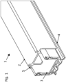
- Fig. 1
- eine schematische perspektivische Ansicht eines Ausschnitts eines Dichtungsprofils nach einer Ausführungsform der Erfindung.
- Das Dichtungsprofil 1 umfasst ein Führungsprofil 2, ein Tragprofil 3 und eine Dichtung 4. Das Führungsprofil 2 kann an der Unterseite einer Tür befestigt werden und ist U-förmig ausgebildet. Das Tragprofil 3 ist am Führungsprofil 2 angeordnet und ebenfalls U-förmig ausgebildet. Das Tragprofil 3 kann relativ zum Führungsprofil abgesenkt oder angehoben werden. Am Tragprofil 3 ist die Dichtung 4 angeordnet, die ebenfalls profilartig ausgebildet ist.
- Das Führungsprofil 2 weist ein Ende 5 auf, das im an der Tür angebrachten Zustand das Ende ist, das einer der Schließkanten, also Hauptschließkante oder Nebenschließkante, der Tür zugewandt ist. Das Tragprofil 3 ragt über dieses Ende 5 hinaus in Richtung der jeweiligen Schließkante. Dies ermöglicht, dass sich die Dichtung 4 ebenfalls über das Ende 5 hinaus erstreckt.
- Der Einbau des Dichtungsprofils 1 kann beispielsweise an Türen erfolgen, bei denen aus bautechnischen Gründen das Führungsprofil 2 nicht bis zu einer der Schließkanten oder bis zu beiden Schließkanten reichen kann. Mit dem Dichtungsprofil 1 kann auch in diesem Fall eine zuverlässige Abdichtung erreicht werden.
- In
Figur 1 ist lediglich ein Endbereich des Dichtungsprofils 1 dargestellt. Der diesem Endbereich gegenüberliegende Endbereich kann genauso oder wie aus dem Stand der Technik bekannt ausgestaltet sein. Es ist also möglich, dass im gegenüberliegenden Endbereich das Tragprofil 3 ebenfalls über das dortige Ende des Führungsprofils 2 hinaus ragt.
Claims (10)
- Dichtungsprofil (1) für eine Tür, umfassend ein Führungsprofil (2) und ein Tragprofil (3), wobei
das Tragprofil (3) an zumindest einem Ende (5) des Führungsprofils (2) über das Ende (5) des Führungsprofils (2) zumindest ca. 0,5cm hinaus ragt, wobei das Dichtungsprofil (1) eine Dichtung (4) umfasst, die am Tragprofil (3) angeordnet ist, wobei das Tragprofil (3) teilweise innerhalb des Führungsprofils (2) angeordnet ist, dadurch gekennzeichnet, dass die Dichtung (4) an zumindest einem Ende des Tragprofils (3) über das Ende des Tragprofils (3) hinausragt, und dass das Tragprofil (3) an beiden Enden des Führungsprofil (2) über die Enden des Führungsprofils (2) hinaus ragt. - Dichtungsprofil (1) nach Anspruch 1, dadurch gekennzeichnet, dass das Führungsprofil (2) zur Befestigung an der Tür ausgebildet ist.
- Dichtungsprofil (1) nach zumindest einem der vorherigen Ansprüche, dadurch gekennzeichnet, dass die Dichtung (4) an zumindest einem Ende (5) des Führungsprofils (2) über das Ende (5) des Führungsprofils (2) hinaus ragt.
- Dichtungsprofil (1) nach dem vorherigen Anspruch, dadurch gekennzeichnet, dass die Dichtung ein Elastomer umfasst.
- Dichtungsprofil (1) nach zumindest einem der vorherigen Ansprüche, dadurch gekennzeichnet, dass das Tragprofil (3) relativ zum Führungsprofil (2) automatisch anhebbar und absenkbar ist.
- Dichtungsprofil (1) nach zumindest einem der vorherigen Ansprüche, dadurch gekennzeichnet, dass das Tragprofil (3) U-förmig ausgebildet ist.
- Dichtungsprofil (1) nach zumindest einem der vorherigen Ansprüche, dadurch gekennzeichnet, dass das Führungsprofil (2) U-förmig ausgebildet ist.
- Dichtungsprofil (1) nach zumindest einem der vorherigen Ansprüche, dadurch gekennzeichnet, dass das Tragprofil (3) Kunststoff, Stahl, Edelstahl oder Aluminium umfasst.
- Dichtungsprofil (1) nach zumindest einem der vorherigen Ansprüche, dadurch gekennzeichnet, dass das Tragprofil (3) an einem Ende der Dichtung (4) über das Ende der Dichtung (4) hinausragt.
- Tür, umfassend ein Dichtungsprofil (1) nach zumindest einem der vorherigen Ansprüche.
Priority Applications (1)
| Application Number | Priority Date | Filing Date | Title |
|---|---|---|---|
| EP16153888.9A EP3203006B2 (de) | 2016-02-02 | 2016-02-02 | Dichtungsprofil für eine tür |
Applications Claiming Priority (1)
| Application Number | Priority Date | Filing Date | Title |
|---|---|---|---|
| EP16153888.9A EP3203006B2 (de) | 2016-02-02 | 2016-02-02 | Dichtungsprofil für eine tür |
Publications (3)
| Publication Number | Publication Date |
|---|---|
| EP3203006A1 EP3203006A1 (de) | 2017-08-09 |
| EP3203006B1 EP3203006B1 (de) | 2019-09-04 |
| EP3203006B2 true EP3203006B2 (de) | 2024-10-30 |
Family
ID=55299338
Family Applications (1)
| Application Number | Title | Priority Date | Filing Date |
|---|---|---|---|
| EP16153888.9A Active EP3203006B2 (de) | 2016-02-02 | 2016-02-02 | Dichtungsprofil für eine tür |
Country Status (1)
| Country | Link |
|---|---|
| EP (1) | EP3203006B2 (de) |
Families Citing this family (2)
| Publication number | Priority date | Publication date | Assignee | Title |
|---|---|---|---|---|
| EP3768930B1 (de) | 2018-03-19 | 2023-04-12 | ASSA ABLOY (Schweiz) AG | Dichtungsvorrichtung |
| DE102024109048B3 (de) * | 2024-03-28 | 2025-07-24 | Hörmann K.G. Freisen | Teilesatz für eine Bodendichtung eines Türflügels, insbesondere einer Rauchschutztür, mit Adapter |
Family Cites Families (10)
| Publication number | Priority date | Publication date | Assignee | Title |
|---|---|---|---|---|
| CH265133A (de) | 1949-01-21 | 1949-11-30 | Jaggi & Soehne W | Verschlusseinrichtung an einer schwellenlosen Türe. |
| DE1095500B (de) | 1959-02-17 | 1960-12-22 | Athmer Fa F | Tuerabdichtung |
| JP3015271B2 (ja) | 1994-12-22 | 2000-03-06 | 株式会社ニチベイ | 扉のシールジャッキ機構 |
| DE20011070U1 (de) | 2000-06-23 | 2000-09-07 | Fa. F. Athmer, 59757 Arnsberg | Dichtungsvorrichtung für einen unteren Türspalt |
| EP2085559B1 (de) | 2008-02-04 | 2016-12-14 | Planet GDZ AG | Absenkbare Dichtungsvorrichtung |
| US20110113696A1 (en) | 2009-11-19 | 2011-05-19 | Gallagher Gerald B | Draft blocker assembly for lifting a draft blocker and method |
| DE202010010057U1 (de) | 2010-07-09 | 2010-10-28 | Planet Gdz Ag | Türdichtungssystem mit Befestigungselement |
| DE202011001104U1 (de) | 2011-01-07 | 2012-04-26 | Athmer Ohg | Dichtungsvorrichtung mit einem Dichtungsprofil und einem Mechanismus zum Verschieben des Dichtungsprofils bei Betätigung des Mechanismus |
| DE202011051326U1 (de) | 2011-09-16 | 2012-12-17 | Athmer Ohg | Dichtung für Türen, Fenster oder Ähnlichem mit einer absenkbaren Dichtleiste |
| NL2012920B1 (nl) | 2014-05-30 | 2016-06-09 | Elton Bv | Deurafdichting, deur met deurafdichting en werkwijze voor het vervaardigen daarvan. |
-
2016
- 2016-02-02 EP EP16153888.9A patent/EP3203006B2/de active Active
Also Published As
| Publication number | Publication date |
|---|---|
| EP3203006B1 (de) | 2019-09-04 |
| EP3203006A1 (de) | 2017-08-09 |
Similar Documents
| Publication | Publication Date | Title |
|---|---|---|
| EP3508680A1 (de) | Dichtvorrichtung und damit versehenes sektionaltor | |
| DE102016125602A1 (de) | Isolierkörper für mehrschalige Bauelemente | |
| EP3203006B2 (de) | Dichtungsprofil für eine tür | |
| EP2639391A1 (de) | Schiebe- und Drehflügelsystem | |
| CH655869A5 (en) | Device for fastening a cover rail and for guiding an espagnolette of an espagnolette fitting cuttable to length | |
| WO2017001226A1 (de) | Absenkdichtung | |
| EP3241974A1 (de) | Anordnung für eine dichtung, insbesondere für eine auflaufdichtung oder für eine sich selbsttätig absenkende bodendichtung für türen | |
| DE1187779B (de) | Abdichtvorrichtung fuer Fenster, Tueren od. dgl. | |
| DE2517367C3 (de) | Beschlag für Kipp-Schwenkflügel von Fenstern, Türen od.dgl. | |
| CH657179A5 (de) | System zur fuehrung und fixierung von beschlaegen an tueren oder fenstern. | |
| DE202016101599U1 (de) | Dichtungsprofil für eine Tür | |
| EP4345239A1 (de) | Rahmen zum einfassen mindestens einer scheibe und vorrichtung umfassend den rahmen und eine zarge | |
| DE202019102317U1 (de) | Hebe-Schiebe-Tür oder Hebe-Schiebe-Fenster | |
| DE19814498B4 (de) | Stulpschienenbeschlag | |
| AT521543A2 (de) | Schutzvorrichtung für Roll- und Sektionaltore | |
| DE3833561C2 (de) | ||
| EP3425149A1 (de) | Hebe-schiebe-einrichtung, insbesondere hebe-schiebe-tür oder hebe-schiebe-fenster | |
| DE102019209055B3 (de) | Schiebetüranlage | |
| DE8803841U1 (de) | Flachstulpe | |
| DE2041376A1 (de) | Fensterrahmenanordnung mit zusaetzlichen Blenden | |
| DE20311828U1 (de) | Schließeinrichtung | |
| DE202015104997U1 (de) | Führungsvorrichtung für Rollläden | |
| CH655352A5 (de) | Fenster- oder tuerfluegel. | |
| EP3088639B1 (de) | Vorrichtung zum ausrichten von einander gegenüberstehend anzuordnenden beschlagteilen | |
| DE20015067U1 (de) | Fenster |
Legal Events
| Date | Code | Title | Description |
|---|---|---|---|
| PUAI | Public reference made under article 153(3) epc to a published international application that has entered the european phase |
Free format text: ORIGINAL CODE: 0009012 |
|
| STAA | Information on the status of an ep patent application or granted ep patent |
Free format text: STATUS: THE APPLICATION HAS BEEN PUBLISHED |
|
| AK | Designated contracting states |
Kind code of ref document: A1 Designated state(s): AL AT BE BG CH CY CZ DE DK EE ES FI FR GB GR HR HU IE IS IT LI LT LU LV MC MK MT NL NO PL PT RO RS SE SI SK SM TR |
|
| AX | Request for extension of the european patent |
Extension state: BA ME |
|
| STAA | Information on the status of an ep patent application or granted ep patent |
Free format text: STATUS: REQUEST FOR EXAMINATION WAS MADE |
|
| 17P | Request for examination filed |
Effective date: 20180209 |
|
| RAV | Requested validation state of the european patent: fee paid |
Extension state: MD Effective date: 20180209 Extension state: MA Effective date: 20180209 |
|
| RAX | Requested extension states of the european patent have changed |
Extension state: BA Payment date: 20180209 Extension state: ME Payment date: 20180209 |
|
| RBV | Designated contracting states (corrected) |
Designated state(s): AL AT BE BG CH CY CZ DE DK EE ES FI FR GB GR HR HU IE IS IT LI LT LU LV MC MK MT NL NO PL PT RO RS SE SI SK SM TR |
|
| RAV | Requested validation state of the european patent: fee paid |
Extension state: MD Effective date: 20180409 Extension state: MA Effective date: 20180409 |
|
| RAX | Requested extension states of the european patent have changed |
Extension state: BA Payment date: 20180409 Extension state: ME Payment date: 20180409 |
|
| GRAP | Despatch of communication of intention to grant a patent |
Free format text: ORIGINAL CODE: EPIDOSNIGR1 |
|
| STAA | Information on the status of an ep patent application or granted ep patent |
Free format text: STATUS: GRANT OF PATENT IS INTENDED |
|
| INTG | Intention to grant announced |
Effective date: 20190515 |
|
| GRAS | Grant fee paid |
Free format text: ORIGINAL CODE: EPIDOSNIGR3 |
|
| GRAA | (expected) grant |
Free format text: ORIGINAL CODE: 0009210 |
|
| STAA | Information on the status of an ep patent application or granted ep patent |
Free format text: STATUS: THE PATENT HAS BEEN GRANTED |
|
| AK | Designated contracting states |
Kind code of ref document: B1 Designated state(s): AL AT BE BG CH CY CZ DE DK EE ES FI FR GB GR HR HU IE IS IT LI LT LU LV MC MK MT NL NO PL PT RO RS SE SI SK SM TR |
|
| REG | Reference to a national code |
Ref country code: GB Ref legal event code: FG4D Free format text: NOT ENGLISH |
|
| REG | Reference to a national code |
Ref country code: CH Ref legal event code: EP |
|
| REG | Reference to a national code |
Ref country code: AT Ref legal event code: REF Ref document number: 1175577 Country of ref document: AT Kind code of ref document: T Effective date: 20190915 |
|
| REG | Reference to a national code |
Ref country code: DE Ref legal event code: R096 Ref document number: 502016006368 Country of ref document: DE Ref country code: IE Ref legal event code: FG4D Free format text: LANGUAGE OF EP DOCUMENT: GERMAN |
|
| REG | Reference to a national code |
Ref country code: NL Ref legal event code: MP Effective date: 20190904 |
|
| REG | Reference to a national code |
Ref country code: LT Ref legal event code: MG4D |
|
| PG25 | Lapsed in a contracting state [announced via postgrant information from national office to epo] |
Ref country code: SE Free format text: LAPSE BECAUSE OF FAILURE TO SUBMIT A TRANSLATION OF THE DESCRIPTION OR TO PAY THE FEE WITHIN THE PRESCRIBED TIME-LIMIT Effective date: 20190904 Ref country code: BG Free format text: LAPSE BECAUSE OF FAILURE TO SUBMIT A TRANSLATION OF THE DESCRIPTION OR TO PAY THE FEE WITHIN THE PRESCRIBED TIME-LIMIT Effective date: 20191204 Ref country code: NO Free format text: LAPSE BECAUSE OF FAILURE TO SUBMIT A TRANSLATION OF THE DESCRIPTION OR TO PAY THE FEE WITHIN THE PRESCRIBED TIME-LIMIT Effective date: 20191204 Ref country code: HR Free format text: LAPSE BECAUSE OF FAILURE TO SUBMIT A TRANSLATION OF THE DESCRIPTION OR TO PAY THE FEE WITHIN THE PRESCRIBED TIME-LIMIT Effective date: 20190904 Ref country code: FI Free format text: LAPSE BECAUSE OF FAILURE TO SUBMIT A TRANSLATION OF THE DESCRIPTION OR TO PAY THE FEE WITHIN THE PRESCRIBED TIME-LIMIT Effective date: 20190904 Ref country code: LT Free format text: LAPSE BECAUSE OF FAILURE TO SUBMIT A TRANSLATION OF THE DESCRIPTION OR TO PAY THE FEE WITHIN THE PRESCRIBED TIME-LIMIT Effective date: 20190904 |
|
| PG25 | Lapsed in a contracting state [announced via postgrant information from national office to epo] |
Ref country code: LV Free format text: LAPSE BECAUSE OF FAILURE TO SUBMIT A TRANSLATION OF THE DESCRIPTION OR TO PAY THE FEE WITHIN THE PRESCRIBED TIME-LIMIT Effective date: 20190904 Ref country code: RS Free format text: LAPSE BECAUSE OF FAILURE TO SUBMIT A TRANSLATION OF THE DESCRIPTION OR TO PAY THE FEE WITHIN THE PRESCRIBED TIME-LIMIT Effective date: 20190904 Ref country code: ES Free format text: LAPSE BECAUSE OF FAILURE TO SUBMIT A TRANSLATION OF THE DESCRIPTION OR TO PAY THE FEE WITHIN THE PRESCRIBED TIME-LIMIT Effective date: 20190904 Ref country code: GR Free format text: LAPSE BECAUSE OF FAILURE TO SUBMIT A TRANSLATION OF THE DESCRIPTION OR TO PAY THE FEE WITHIN THE PRESCRIBED TIME-LIMIT Effective date: 20191205 Ref country code: AL Free format text: LAPSE BECAUSE OF FAILURE TO SUBMIT A TRANSLATION OF THE DESCRIPTION OR TO PAY THE FEE WITHIN THE PRESCRIBED TIME-LIMIT Effective date: 20190904 |
|
| PG25 | Lapsed in a contracting state [announced via postgrant information from national office to epo] |
Ref country code: NL Free format text: LAPSE BECAUSE OF FAILURE TO SUBMIT A TRANSLATION OF THE DESCRIPTION OR TO PAY THE FEE WITHIN THE PRESCRIBED TIME-LIMIT Effective date: 20190904 Ref country code: PT Free format text: LAPSE BECAUSE OF FAILURE TO SUBMIT A TRANSLATION OF THE DESCRIPTION OR TO PAY THE FEE WITHIN THE PRESCRIBED TIME-LIMIT Effective date: 20200106 Ref country code: PL Free format text: LAPSE BECAUSE OF FAILURE TO SUBMIT A TRANSLATION OF THE DESCRIPTION OR TO PAY THE FEE WITHIN THE PRESCRIBED TIME-LIMIT Effective date: 20190904 Ref country code: RO Free format text: LAPSE BECAUSE OF FAILURE TO SUBMIT A TRANSLATION OF THE DESCRIPTION OR TO PAY THE FEE WITHIN THE PRESCRIBED TIME-LIMIT Effective date: 20190904 Ref country code: IT Free format text: LAPSE BECAUSE OF FAILURE TO SUBMIT A TRANSLATION OF THE DESCRIPTION OR TO PAY THE FEE WITHIN THE PRESCRIBED TIME-LIMIT Effective date: 20190904 Ref country code: EE Free format text: LAPSE BECAUSE OF FAILURE TO SUBMIT A TRANSLATION OF THE DESCRIPTION OR TO PAY THE FEE WITHIN THE PRESCRIBED TIME-LIMIT Effective date: 20190904 |
|
| PG25 | Lapsed in a contracting state [announced via postgrant information from national office to epo] |
Ref country code: IS Free format text: LAPSE BECAUSE OF FAILURE TO SUBMIT A TRANSLATION OF THE DESCRIPTION OR TO PAY THE FEE WITHIN THE PRESCRIBED TIME-LIMIT Effective date: 20200224 Ref country code: SM Free format text: LAPSE BECAUSE OF FAILURE TO SUBMIT A TRANSLATION OF THE DESCRIPTION OR TO PAY THE FEE WITHIN THE PRESCRIBED TIME-LIMIT Effective date: 20190904 Ref country code: CZ Free format text: LAPSE BECAUSE OF FAILURE TO SUBMIT A TRANSLATION OF THE DESCRIPTION OR TO PAY THE FEE WITHIN THE PRESCRIBED TIME-LIMIT Effective date: 20190904 Ref country code: SK Free format text: LAPSE BECAUSE OF FAILURE TO SUBMIT A TRANSLATION OF THE DESCRIPTION OR TO PAY THE FEE WITHIN THE PRESCRIBED TIME-LIMIT Effective date: 20190904 |
|
| REG | Reference to a national code |
Ref country code: DE Ref legal event code: R026 Ref document number: 502016006368 Country of ref document: DE |
|
| PLBI | Opposition filed |
Free format text: ORIGINAL CODE: 0009260 |
|
| PLAX | Notice of opposition and request to file observation + time limit sent |
Free format text: ORIGINAL CODE: EPIDOSNOBS2 |
|
| 26 | Opposition filed |
Opponent name: ASSA ABLOY (SCHWEIZ) AG Effective date: 20200602 |
|
| PG2D | Information on lapse in contracting state deleted |
Ref country code: IS |
|
| PG25 | Lapsed in a contracting state [announced via postgrant information from national office to epo] |
Ref country code: DK Free format text: LAPSE BECAUSE OF FAILURE TO SUBMIT A TRANSLATION OF THE DESCRIPTION OR TO PAY THE FEE WITHIN THE PRESCRIBED TIME-LIMIT Effective date: 20190904 Ref country code: IS Free format text: LAPSE BECAUSE OF FAILURE TO SUBMIT A TRANSLATION OF THE DESCRIPTION OR TO PAY THE FEE WITHIN THE PRESCRIBED TIME-LIMIT Effective date: 20200105 |
|
| PG25 | Lapsed in a contracting state [announced via postgrant information from national office to epo] |
Ref country code: SI Free format text: LAPSE BECAUSE OF FAILURE TO SUBMIT A TRANSLATION OF THE DESCRIPTION OR TO PAY THE FEE WITHIN THE PRESCRIBED TIME-LIMIT Effective date: 20190904 |
|
| PLBB | Reply of patent proprietor to notice(s) of opposition received |
Free format text: ORIGINAL CODE: EPIDOSNOBS3 |
|
| REG | Reference to a national code |
Ref country code: BE Ref legal event code: MM Effective date: 20200229 |
|
| PG25 | Lapsed in a contracting state [announced via postgrant information from national office to epo] |
Ref country code: LU Free format text: LAPSE BECAUSE OF NON-PAYMENT OF DUE FEES Effective date: 20200202 Ref country code: MC Free format text: LAPSE BECAUSE OF FAILURE TO SUBMIT A TRANSLATION OF THE DESCRIPTION OR TO PAY THE FEE WITHIN THE PRESCRIBED TIME-LIMIT Effective date: 20190904 |
|
| PG25 | Lapsed in a contracting state [announced via postgrant information from national office to epo] |
Ref country code: IE Free format text: LAPSE BECAUSE OF NON-PAYMENT OF DUE FEES Effective date: 20200202 Ref country code: FR Free format text: LAPSE BECAUSE OF NON-PAYMENT OF DUE FEES Effective date: 20200229 |
|
| PG25 | Lapsed in a contracting state [announced via postgrant information from national office to epo] |
Ref country code: BE Free format text: LAPSE BECAUSE OF NON-PAYMENT OF DUE FEES Effective date: 20200229 |
|
| PG25 | Lapsed in a contracting state [announced via postgrant information from national office to epo] |
Ref country code: TR Free format text: LAPSE BECAUSE OF FAILURE TO SUBMIT A TRANSLATION OF THE DESCRIPTION OR TO PAY THE FEE WITHIN THE PRESCRIBED TIME-LIMIT Effective date: 20190904 Ref country code: MT Free format text: LAPSE BECAUSE OF FAILURE TO SUBMIT A TRANSLATION OF THE DESCRIPTION OR TO PAY THE FEE WITHIN THE PRESCRIBED TIME-LIMIT Effective date: 20190904 Ref country code: CY Free format text: LAPSE BECAUSE OF FAILURE TO SUBMIT A TRANSLATION OF THE DESCRIPTION OR TO PAY THE FEE WITHIN THE PRESCRIBED TIME-LIMIT Effective date: 20190904 |
|
| PG25 | Lapsed in a contracting state [announced via postgrant information from national office to epo] |
Ref country code: MK Free format text: LAPSE BECAUSE OF FAILURE TO SUBMIT A TRANSLATION OF THE DESCRIPTION OR TO PAY THE FEE WITHIN THE PRESCRIBED TIME-LIMIT Effective date: 20190904 |
|
| APBM | Appeal reference recorded |
Free format text: ORIGINAL CODE: EPIDOSNREFNO |
|
| APBP | Date of receipt of notice of appeal recorded |
Free format text: ORIGINAL CODE: EPIDOSNNOA2O |
|
| APAH | Appeal reference modified |
Free format text: ORIGINAL CODE: EPIDOSCREFNO |
|
| APAL | Date of receipt of statement of grounds of an appeal modified |
Free format text: ORIGINAL CODE: EPIDOSCNOA3O |
|
| APBQ | Date of receipt of statement of grounds of appeal recorded |
Free format text: ORIGINAL CODE: EPIDOSNNOA3O |
|
| APAH | Appeal reference modified |
Free format text: ORIGINAL CODE: EPIDOSCREFNO |
|
| P01 | Opt-out of the competence of the unified patent court (upc) registered |
Effective date: 20230616 |
|
| APBU | Appeal procedure closed |
Free format text: ORIGINAL CODE: EPIDOSNNOA9O |
|
| PUAH | Patent maintained in amended form |
Free format text: ORIGINAL CODE: 0009272 |
|
| STAA | Information on the status of an ep patent application or granted ep patent |
Free format text: STATUS: PATENT MAINTAINED AS AMENDED |
|
| 27A | Patent maintained in amended form |
Effective date: 20241030 |
|
| AK | Designated contracting states |
Kind code of ref document: B2 Designated state(s): AL AT BE BG CH CY CZ DE DK EE ES FI FR GB GR HR HU IE IS IT LI LT LU LV MC MK MT NL NO PL PT RO RS SE SI SK SM TR |
|
| REG | Reference to a national code |
Ref country code: DE Ref legal event code: R102 Ref document number: 502016006368 Country of ref document: DE |
|
| PGFP | Annual fee paid to national office [announced via postgrant information from national office to epo] |
Ref country code: DE Payment date: 20250228 Year of fee payment: 10 |
|
| PGFP | Annual fee paid to national office [announced via postgrant information from national office to epo] |
Ref country code: AT Payment date: 20250219 Year of fee payment: 10 Ref country code: CH Payment date: 20250301 Year of fee payment: 10 |
|
| PGFP | Annual fee paid to national office [announced via postgrant information from national office to epo] |
Ref country code: GB Payment date: 20250220 Year of fee payment: 10 |
|
| REG | Reference to a national code |
Ref country code: CH Ref legal event code: U11 Free format text: ST27 STATUS EVENT CODE: U-0-0-U10-U11 (AS PROVIDED BY THE NATIONAL OFFICE) Effective date: 20260301 |