EP3202307A1 - Laryngoskop - Google Patents
Laryngoskop Download PDFInfo
- Publication number
- EP3202307A1 EP3202307A1 EP17000129.1A EP17000129A EP3202307A1 EP 3202307 A1 EP3202307 A1 EP 3202307A1 EP 17000129 A EP17000129 A EP 17000129A EP 3202307 A1 EP3202307 A1 EP 3202307A1
- Authority
- EP
- European Patent Office
- Prior art keywords
- handle
- channel
- spatula
- ribs
- laryngoscope
- Prior art date
- Legal status (The legal status is an assumption and is not a legal conclusion. Google has not performed a legal analysis and makes no representation as to the accuracy of the status listed.)
- Granted
Links
Images


Classifications
-
- A—HUMAN NECESSITIES
- A61—MEDICAL OR VETERINARY SCIENCE; HYGIENE
- A61B—DIAGNOSIS; SURGERY; IDENTIFICATION
- A61B1/00—Instruments for performing medical examinations of the interior of cavities or tubes of the body by visual or photographical inspection, e.g. endoscopes; Illuminating arrangements therefor
- A61B1/267—Instruments for performing medical examinations of the interior of cavities or tubes of the body by visual or photographical inspection, e.g. endoscopes; Illuminating arrangements therefor for the respiratory tract, e.g. laryngoscopes, bronchoscopes
-
- A—HUMAN NECESSITIES
- A61—MEDICAL OR VETERINARY SCIENCE; HYGIENE
- A61B—DIAGNOSIS; SURGERY; IDENTIFICATION
- A61B1/00—Instruments for performing medical examinations of the interior of cavities or tubes of the body by visual or photographical inspection, e.g. endoscopes; Illuminating arrangements therefor
- A61B1/00064—Constructional details of the endoscope body
- A61B1/00066—Proximal part of endoscope body, e.g. handles
-
- A—HUMAN NECESSITIES
- A61—MEDICAL OR VETERINARY SCIENCE; HYGIENE
- A61B—DIAGNOSIS; SURGERY; IDENTIFICATION
- A61B1/00—Instruments for performing medical examinations of the interior of cavities or tubes of the body by visual or photographical inspection, e.g. endoscopes; Illuminating arrangements therefor
- A61B1/00064—Constructional details of the endoscope body
- A61B1/00071—Insertion part of the endoscope body
- A61B1/0008—Insertion part of the endoscope body characterised by distal tip features
- A61B1/00101—Insertion part of the endoscope body characterised by distal tip features the distal tip features being detachable
-
- A—HUMAN NECESSITIES
- A61—MEDICAL OR VETERINARY SCIENCE; HYGIENE
- A61B—DIAGNOSIS; SURGERY; IDENTIFICATION
- A61B1/00—Instruments for performing medical examinations of the interior of cavities or tubes of the body by visual or photographical inspection, e.g. endoscopes; Illuminating arrangements therefor
- A61B1/00147—Holding or positioning arrangements
- A61B1/00154—Holding or positioning arrangements using guiding arrangements for insertion
-
- A—HUMAN NECESSITIES
- A61—MEDICAL OR VETERINARY SCIENCE; HYGIENE
- A61B—DIAGNOSIS; SURGERY; IDENTIFICATION
- A61B1/00—Instruments for performing medical examinations of the interior of cavities or tubes of the body by visual or photographical inspection, e.g. endoscopes; Illuminating arrangements therefor
- A61B1/012—Instruments for performing medical examinations of the interior of cavities or tubes of the body by visual or photographical inspection, e.g. endoscopes; Illuminating arrangements therefor characterised by internal passages or accessories therefor
-
- A—HUMAN NECESSITIES
- A61—MEDICAL OR VETERINARY SCIENCE; HYGIENE
- A61B—DIAGNOSIS; SURGERY; IDENTIFICATION
- A61B1/00—Instruments for performing medical examinations of the interior of cavities or tubes of the body by visual or photographical inspection, e.g. endoscopes; Illuminating arrangements therefor
- A61B1/012—Instruments for performing medical examinations of the interior of cavities or tubes of the body by visual or photographical inspection, e.g. endoscopes; Illuminating arrangements therefor characterised by internal passages or accessories therefor
- A61B1/0125—Endoscope within endoscope
-
- A—HUMAN NECESSITIES
- A61—MEDICAL OR VETERINARY SCIENCE; HYGIENE
- A61B—DIAGNOSIS; SURGERY; IDENTIFICATION
- A61B1/00—Instruments for performing medical examinations of the interior of cavities or tubes of the body by visual or photographical inspection, e.g. endoscopes; Illuminating arrangements therefor
- A61B1/04—Instruments for performing medical examinations of the interior of cavities or tubes of the body by visual or photographical inspection, e.g. endoscopes; Illuminating arrangements therefor combined with photographic or television appliances
-
- A—HUMAN NECESSITIES
- A61—MEDICAL OR VETERINARY SCIENCE; HYGIENE
- A61B—DIAGNOSIS; SURGERY; IDENTIFICATION
- A61B1/00—Instruments for performing medical examinations of the interior of cavities or tubes of the body by visual or photographical inspection, e.g. endoscopes; Illuminating arrangements therefor
- A61B1/04—Instruments for performing medical examinations of the interior of cavities or tubes of the body by visual or photographical inspection, e.g. endoscopes; Illuminating arrangements therefor combined with photographic or television appliances
- A61B1/05—Instruments for performing medical examinations of the interior of cavities or tubes of the body by visual or photographical inspection, e.g. endoscopes; Illuminating arrangements therefor combined with photographic or television appliances characterised by the image sensor, e.g. camera, being in the distal end portion
- A61B1/053—Instruments for performing medical examinations of the interior of cavities or tubes of the body by visual or photographical inspection, e.g. endoscopes; Illuminating arrangements therefor combined with photographic or television appliances characterised by the image sensor, e.g. camera, being in the distal end portion being detachable
Definitions
- the invention relates to a laryngoscope with a handle, at the distal end at an angle to the longitudinal axis of the handle a spatula is arranged, wherein in the handle and in the spatula a channel for receiving an image guide of a video endoscope is formed so that the channel in a Transition area from the handle to the spatula merges in a radius from the handle into the spatula.
- Laryngoscopes are used for direct examination and examination of the larynx.
- a generic laryngoscope is for example from the DE 199 55 180 B4 known.
- the image guide serves to pick up an image in the region of the distal end of the spatula and to transmit it to an image reproduction unit spatially separate from the spatula.
- the image guide is in the video laryngoscopes usually made of a cable, at the distal end of a video chip is arranged.
- spatula is arranged substantially at right angles to the longitudinal axis of the handle at the distal end of the handle, also formed in the handle and spatula channel for receiving the image conductor of a video endoscope in the transition region from the handle to the spatula on a strong bend, which in the Practice is designed as a radius.
- a generic video laryngoscope is, for example, the C-MAC® S of Karl Storz GmbH & Co. KG.
- the object of the invention is to provide a laryngoscope which, with simple handling, ensures material-gentle insertion of the image guide into the image guide channel.
- the solution to this problem is inventively characterized in that in the transition region from the handle in the spatula in the interior of the channel at least one run-on slope is formed.
- the inventive design of serving as a guide for the image guide run-in inside the channel it is possible for the first time to guide the image guide without upsetting also to tight radii.
- the run-up slope consists of a plurality of spaced-apart ribs.
- This embodiment reduces the weight, since less material must be used for the run-up slope and also provides by the mutually parallel ribs a very good guide for the introduced into the channel image guide.
- the mutually spaced ribs are aligned parallel to each other.
- the ribs viewed in the insertion direction of the image guide, are formed on the proximal side of the strongest curvature of the radius on the channel inner wall. This arrangement of the ribs in the insertion direction before the strongest bend ensures that the image guide is passed at the correct angle and without the risk of upsetting in the transition region between the handle and spatula.
- the ribs at an angle to Longitudinal axis of the handle are aligned.
- the angled orientation of the ribs is designed so that the ribs are arranged in the radius pointing into the channel inner wall.
- the positional insertion of the image guide into the channel can be further facilitated according to the invention in that the ribs also narrow the clear diameter of the channel, since they have over their axial length from proximal to distal an increasing radial thickness.
- the ribs are formed fully circumferentially over the entire circumference of the channel inner wall.
- the ribs are formed only in sections over the circumference of the channel inner wall.
- the ribs are formed only in sections, they can be divided over one or more sections over the circumference of the channel inner wall.
- the angle at which the spatula is angled relative to the longitudinal axis of the handle is preferably 70 ° to 90 °.
- the handle and the spatula are detachably connected to each other. This embodiment allows the use of differently shaped spatula while maintaining the handle.
- laryngoscopes are made in practice of a plastic material made in one piece or consist of two half-shells and are often used as disposable articles, this two-part embodiment may be useful to keep the widest possible range of laryngoscope shapes available.
- illustrated laryngoscope 1 consists of a handle 2 and a at the distal end of the handle 2 at an angle to the longitudinal axis 3 of the handle 2 arranged spatula 4th
- the spatula 4 is oriented essentially at right angles to the longitudinal axis 3 of the handle 2.
- the angle at which the spatula 4 is angled relative to the longitudinal axis 3 of the handle 2 70 ° to 90 °.
- Such used as disposable laryngoscopes 1 are usually made of a plastic material and are preferably made of two half-shells produced by injection molding.
- a channel 7 is formed in the laryngoscope 1, which merges in the transition region 8 from the handle 2 to the spatula 4 in a radius from the handle 2 in the spatula 4.
- the channel 7 extending from the handle 2 into the spatula 4 is designed to be open at the proximal end in the handle 2 for introducing the image conductor 5, while the distal end of the channel 7 located in the spatula is normally closed by a window 9.
- the component designated here as the image conductor 5 of the laryngoscope 1 is a cable 10, at the distal end of which a video chip 11 is arranged.
- the spatula 4 is angled at an angle of 70 ° to 90 ° relative to the longitudinal axis 3 of the handle 2 and thus the radius in which the channel 7 in the transition region 8 from the handle 2 in the spatula 4 is very narrow and on the other hand, the image guide 5 of the video endoscope 6 has a certain rigidity, there is the risk during insertion of the image guide 5 into the channel 7 that the image guide 5 touches in the radius of the transition region 8 and is compressed. These compressions of the image guide 5 can lead to a lasting damage to the image guide 5 and thus a deterioration of the image transmission.
- Fig. 1 and 2 illustrated laryngoscope 1, as in particular from Fig. 2 it can be seen in the transition region 8 from the handle 2 in the spatula 4 in the interior of the channel 7 at least one run-on slope 12 is formed.
- the channel 7 tapered run-on slope 12 is used in the interior of the channel 7 as a guide for the image guide 5 and thus allows the image guide 5 without upsetting also to guide tight radii.
- the run-on slope 12 consists of several parallel and spaced-apart ribs 13. This embodiment reduces the weight, since less material for the run-on slope 12 must be used and also provides by the mutually parallel ribs 13 is a very good guide for the into the channel 7 to be introduced image guide. 5
- the ribs 13 are oriented in the illustrated embodiment in the channel 7 facing at an angle ⁇ to the longitudinal axis 3 of the handle 2. This angled orientation of the ribs 13 is designed so that the ribs 13 are arranged pointing into the radius in the channel inner wall 14 of the channel 7.
- the ribs 13 forming the run-on slope 9 are, viewed in the insertion direction of the image guide 5 in the channel 7, formed on the proximal side of the strongest curvature of the radius on the channel inner wall 14. This arrangement of the ribs 13 in the insertion direction before the strongest bend ensures that the image guide 5 in correct angle and without danger of crushing in the transition region 8 between the handle 2 and spatula 4 is passed.
- the ribs 13 may additionally be formed so that they narrow in addition to the bend by the angle ⁇ to the longitudinal axis 3 of the handle 2 and the clear diameter of the channel 7, as it over its axial length from proximal to distal an increasing radial thickness exhibit.
- the arrangement of the ribs 13 on the channel inner wall 14 may be designed so that the ribs 13 are either fully formed over the entire circumference of the channel inner wall 14 or are formed only in sections over the circumference of the channel inner wall 14. In the sectional formation of the ribs 13, these can be divided over one or more sections over the circumference of the channel inner wall 14.
- a laryngoscope 1 designed as described above ensures easy insertion of the image guide 5 into the channel 7.
Landscapes
- Health & Medical Sciences (AREA)
- Life Sciences & Earth Sciences (AREA)
- Surgery (AREA)
- Radiology & Medical Imaging (AREA)
- Engineering & Computer Science (AREA)
- Veterinary Medicine (AREA)
- Biophysics (AREA)
- Nuclear Medicine, Radiotherapy & Molecular Imaging (AREA)
- Optics & Photonics (AREA)
- Pathology (AREA)
- Public Health (AREA)
- General Health & Medical Sciences (AREA)
- Physics & Mathematics (AREA)
- Biomedical Technology (AREA)
- Heart & Thoracic Surgery (AREA)
- Medical Informatics (AREA)
- Molecular Biology (AREA)
- Animal Behavior & Ethology (AREA)
- Otolaryngology (AREA)
- Physiology (AREA)
- Pulmonology (AREA)
- Endoscopes (AREA)
Abstract
Description
- Die Erfindung betrifft ein Laryngoskop mit einem Handgriff, an dessen distalem Ende in einem Winkel zur Längsachse des Handgriffs ein Spatel angeordnet ist, wobei im Handgriff und im Spatel ein Kanal zur Aufnahme eines Bildleiters eines Video-Endoskops so ausgebildet ist, dass der Kanal in einem Übergangsbereich vom Handgriff zum Spatel in einem Radius vom Handgriff in den Spatel übergeht.
- Laryngoskope dienen zur direkten Betrachtung und Untersuchung des Kehlkopfes. Ein gattungsgemäßes Laryngoskop ist beispielsweise aus der
DE 199 55 180 B4 bekannt. Bei dem bekannten, als Video-Laryngoskop ausgebildeten Laryngoskop dient der Bildleiter dazu, ein Bild im Bereich des distalen Endes des Spatels aufzunehmen und an eine vom Spatel räumlich getrennte Bildwiedergabeeinheit zu übertragen. Der Bildleiter besteht bei den Video-Laryngoskopen in der Regel aus einem Kabel, an dessen distalem Ende ein Video-Chip angeordnet ist. - Da der Spatel im Wesentlichen rechtwinklig zur Längsachse des Handgriffs am distalen Ende des Handgriffs angeordnet ist, weist auch der im Handgriff und im Spatel ausgebildete Kanal zur Aufnahme des Bildleiters eines Video-Endoskops im Übergangsbereich vom Handgriff zum Spatel eine starke Abwinklung auf, die in der Praxis als Radius ausgebildet ist.
- Ein gattungsgemäßes Video-Laryngoskop ist beispielsweise das C-MAC® S der Karl Storz GmbH & Co. KG.
- Beim Einführen des Bildleiters eines Video-Endoskops in den Kanal besteht die Gefahr, dass der Bildleiter in dem abgewinkelten Übergangsbereich vom Handgriff in den Spatel gestaucht wird, was zu einer bleibenden Schädigung des Bildleiters und somit einer Verschlechterung der Bildübertragung führen kann.
- Davon ausgehend liegt der Erfindung die Aufgabe zugrunde, ein Laryngoskop zu schaffen, das bei einfacher Handhabung ein materialschonendes Einführen des Bildleiters in den Bildleiterkanal gewährleistet.
- Die Lösung dieser Aufgabenstellung ist erfindungsgemäß dadurch gekennzeichnet, dass im Übergangsbereich vom Handgriff in den Spatel im Inneren des Kanals mindestens eine Anlaufschräge ausgebildet ist.
- Durch die erfindungsgemäße Ausbildung einer als Führung für den Bildleiter dienenden Anlaufschräge im Inneren des Kanals ist es erstmalig möglich, den Bildleiter stauchungsfrei auch um enge Radien zu führen.
- Gemäß einer praktischen Ausführungsform der Erfindung wird vorgeschlagen, dass die Anlaufschräge aus mehreren mit Abstand zueinander angeordneten Rippen besteht. Diese Ausgestaltung verringert das Gewicht, da weniger Material für die Anlaufschräge verwendet werden muss und bietet darüber hinaus durch die parallel zueinander verlaufenden Rippen eine sehr gute Führung für den in den Kanal einzuführenden Bildleiter. Vorteilhafterweise sind die mit Abstand zueinander angeordneten Rippen parallel zueinander ausgerichtet.
- Mit einer bevorzugten Ausführungsform zur Ausbildung der gerippten Anlaufschräge wird vorgeschlagen, dass die Rippen, in Einsteckrichtung des Bildleiters betrachtet, proximalseitig der stärksten Krümmung des Radius an der Kanalinnenwand ausgebildet sind. Diese Anordnung der Rippen in Einschubrichtung vor der stärksten Abwinklung stellt sicher, dass der Bildleiter im richtigen Winkel und ohne Stauchgefahr in den Übergangsbereich zwischen Handgriff und Spatel geleitet wird.
- Um das zielgerichtete Einführen des Bildleiters in den Kanal zu erleichtern, wird mit der Erfindung weiterhin vorgeschlagen, dass die Rippen in einem Winkel zur Längsachse des Handgriffs ausgerichtet sind. Die winklige Ausrichtung der Rippen ist dabei so ausgeführt, dass die Rippen in den Radius hinein weisend an der Kanalinnenwand angeordnet sind.
- Das lagegerechte Einführen des Bildleiters in den Kanal kann erfindungsgemäß weiterhin dadurch erleichtert werden, dass die Rippen auch noch den lichten Durchmesser des Kanals verengen, da sie über ihre axiale Länge von proximal nach distal eine ansteigende radiale Dicke aufweisen.
- Weiterhin wird mit der Erfindung vorgeschlagen, dass die Rippen vollumfänglich über den gesamten Umfang der Kanalinnenwand ausgebildet sind.
- Gemäß einer alternativen Ausführungsform der Erfindung wird vorgeschlagen, dass die Rippen nur abschnittsweise über den Umfang der Kanalinnenwand ausgebildet sind. Bei der nur abschnittsweisen Ausbildung der Rippen können diese auf einen oder mehrere Abschnitte über den Umfang der Kanalinnenwand aufgeteilt sein.
- Der Winkel, unter dem der Spatel gegenüber der Längsachse des Handgriffs abgewinkelt ist, beträgt vorzugsweise 70° bis 90°.
- Schließlich wird mit der Erfindung vorgeschlagen, dass der Handgriff und der Spatel lösbar miteinander verbunden sind. Diese Ausgestaltungsform ermöglicht die Verwendung verschieden geformter Spatel bei Beibehaltung des Handgriffs.
- Auch wenn Laryngoskope in der Praxis aus einem Kunststoffmaterial gefertigt einstückig oder aus zwei Halbschalen bestehend ausgebildet sind und häufig als Einwegartikel verwendet werden, kann diese zweiteilige Ausgestaltungsform sinnvoll sein, um eine möglichst große Bandbreite an Laryngoskopformen vorrätig zu halten.
- Weitere Merkmale und Vorteile der Erfindung ergeben sich anhand der zugehörigen Zeichnungen, in denen ein Ausführungsbeispiel eines erfindungsgemäßen Laryngoskops nur beispielhaft dargestellt ist, ohne die Erfindung auf dieses Ausführungsbeispiel zu beschränken. In den Zeichnungen zeigt:
- Fig. 1
- eine Seitenansicht eines erfindungsgemäßen Laryngoskops mit zugehörigem Video-Endoskop vor dem Zusammenfügen;
- Fig.2
- eine Seitenansicht gemäß
Fig. 1 , jedoch das Laryngoskop mit eingesetztem Video-Endoskop darstellend; - Fig. 3
- eine um 90° gedrehte geschnittene Seitenansicht des Laryngoskops gemäß
Fig. 1 und - Fig. 4
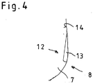
- eine schematische Seitenansicht einer Rippe.
- Das in den Abbildungen
Fig. 1 bis 3 dargestellte Laryngoskop 1 besteht aus einem Handgriff 2 sowie einem am distalen Ende des Handgriffs 2 unter einem Winkel zur Längsachse 3 des Handgriffs 2 angeordneten Spatel 4. - Wie aus den Abbildungen ersichtlich, ist der Spatel 4 im Wesentlichen rechtwinklig zur Längsachse 3 des Handgriffs 2 ausgerichtet. In der Praxis beträgt der Winkel, unter dem der Spatel 4 gegenüber der Längsachse 3 des Handgriffs 2 abgewinkelt ist, 70° bis 90°.
- Derartige als Einwegartikel verwendete Laryngoskope 1 bestehen in der Regel aus einem Kunststoffmaterial und werden vorzugsweise aus zwei im Spritzgussverfahren hergestellten Halbschalen gefertigt.
- Zum Einführen eines Bildleiters 5 eines Video-Endoskops 6 ist im Laryngoskop 1 ein Kanal 7 ausgebildet, der im Übergangsbereich 8 vom Handgriff 2 zum Spatel 4 in einem Radius vom Handgriff 2 in den Spatel 4 übergeht. Der vom Handgriff 2 bis in den Spatel 4 reichende Kanal 7 ist zum Einführen des Bildleiters 5 proximalseitig im Handgriff 2 offen ausgebildet, während das im Spatel gelegene distale Ende des Kanals 7 in der Regel durch ein Fenster 9 verschlossen ist.
- Bei dem hier als Bildleiter 5 des Laryngoskops 1 bezeichneten Bauteil handelt es sich um ein Kabel 10, an dessen distalem Ende ein Video-Chip 11 angeordnet ist.
- Da einerseits der Spatel 4 in einem Winkel von 70° bis 90° gegenüber der Längsachse 3 des Handgriffs 2 abgewinkelt ist und somit auch der Radius in dem der Kanal 7 im Übergangsbereich 8 vom Handgriff 2 in den Spatel 4 sehr eng ist und andererseits der Bildleiter 5 des Video-Endoskops 6 eine gewisse Steifigkeit aufweist, besteht beim Einführen des Bildleiters 5 in den Kanal 7 die Gefahr, dass der Bildleiter 5 im Radius des Übergangsbereichs 8 aufsetzt und gestaucht wird. Diese Stauchungen des Bildleiters 5 können zu einer bleibenden Schädigung des Bildleiters 5 und somit einer Verschlechterung der Bildübertragung führen.
- Um ein stauchungsfreies Einführen des Bildleiters 5 durch den Kanal 7 vom Handgriff 2 hinein in den Spatel 4 zu ermöglichen, ist bei dem in den Abbildungen
Fig. 1 und2 dargestellten Laryngoskop 1, wie insbesondere ausFig. 2 ersichtlich, im Übergangsbereich 8 vom Handgriff 2 in den Spatel 4 im Inneren des Kanals 7 mindestens eine Anlaufschräge 12 ausgebildet. Die den Kanal 7 verjüngende Anlaufschräge 12 dient im Inneren des Kanals 7 als Führung für den Bildleiter 5 und ermöglicht so, den Bildleiter 5 stauchungsfrei auch um enge Radien zu führen. - Bei der in
Fig. 2 dargestellten Ausführungsform besteht die Anlaufschräge 12 aus mehreren parallel und mit Abstand zueinander angeordneten Rippen 13. Diese Ausgestaltung verringert das Gewicht, da weniger Material für die Anlaufschräge 12 verwendet werden muss und bietet darüber hinaus durch die parallel zueinander verlaufenden Rippen 13 eine sehr gute Führung für den in den Kanal 7 einzuführenden Bildleiter 5. - Um das zielgerichtete Einführen des Bildleiters 5 in den Kanal 7 zu erleichtern, sind die Rippen 13 bei der dargestellten Ausführungsform in den Kanal 7 weisend in einem Winkel α zur Längsachse 3 des Handgriffs 2 ausgerichtet. Diese winklige Ausrichtung der Rippen 13 ist dabei so ausgeführt, dass die Rippen 13 in den Radius hinein weisend an der Kanalinnenwand 14 des Kanals 7 angeordnet sind.
- Die die Anlaufschräge 9 bildenden Rippen 13 sind, in Einsteckrichtung des Bildleiters 5 in den Kanal 7 betrachtet, proximalseitig der stärksten Krümmung des Radius an der Kanalinnenwand 14 ausgebildet. Diese Anordnung der Rippen 13 in Einschubrichtung vor der stärksten Abwinklung stellt sicher, dass der Bildleiter 5 im richtigen Winkel und ohne Stauchgefahr in den Übergangsbereich 8 zwischen Handgriff 2 und Spatel 4 geleitet wird.
- Wie aus
Fig. 4 ersichtlich, können die Rippen 13 zusätzlich so ausgebildet sein, dass sie zusätzlich zur Abwinklung um den Winkel α zur Längsachse 3 des Handgriffs 2 auch noch den lichten Durchmesser des Kanals 7 verengen, da sie über ihre axiale Länge von proximal nach distal eine ansteigende radiale Dicke aufweisen. - Die Anordnung der Rippen 13 an der Kanalinnenwand 14 kann so ausgeführt sein dass die Rippen 13 entweder vollumfänglich über den gesamten Umfang der Kanalinnenwand 14 ausgebildet sind oder aber nur abschnittsweise über den Umfang der Kanalinnenwand 14 ausgebildet sind. Bei der abschnittsweisen Ausbildung der Rippen 13 können diese auf einen oder mehrere Abschnitte über den Umfang der Kanalinnenwand 14 aufgeteilt sein.
- Ein wie zuvor beschrieben ausgebildetes Laryngoskop 1 gewährleistet bei einfacher Handhabung ein materialschonendes Einführen des Bildleiters 5 in den Kanal 7.
-
- 1
- Laryngoskop
- 2
- Handgriff
- 3
- Längsachse
- 4
- Spatel
- 5
- Bildleiter
- 6
- Video-Endoskop
- 7
- Kanal
- 8
- Übergangsbereich
- 9
- Fenster
- 10
- Kabel
- 11
- Video-Chip
- 12
- Anlaufschräge
- 13
- Rippe
- 14
- Kanalinnenwand
- α
- Winkel
Claims (10)
- Laryngoskop mit einem Handgriff (2), an dessen distalem Ende in einem Winkel zur Längsachse (3) des Handgriffs (2) ein Spatel (4) angeordnet ist, wobei im Handgriff (2) und im Spatel (4) ein Kanal (7) zur Aufnahme eines Bildleiters (5) eines Video-Endoskops (6) so ausgebildet ist, dass der Kanal (7) in einem Übergangsbereich (8) vom Handgriff (2) zum Spatel (4) in einem Radius vom Handgriff (2) in den Spatel (4) übergeht,
dadurch gekennzeichnet,
dass im Übergangsbereich (8) vom Handgriff (2) in den Spatel (4) im Inneren des Kanals (7) mindestens eine Anlaufschräge (12) ausgebildet ist. - Laryngoskop nach Anspruch 1, dadurch gekennzeichnet, dass die mindestens eine Anlaufschräge (12) aus mehreren mit Abstand zueinander angeordneten Rippen (13) besteht.
- Laryngoskop nach Anspruch 2, dadurch gekennzeichnet, dass die Rippen (13) parallel zueinander angeordnet sind.
- Laryngoskop nach Anspruch 2 oder 3, dadurch gekennzeichnet, dass die Rippen (13), in Einsteckrichtung des Bildleiters (5) betrachtet, proximalseitig der stärksten Krümmung des Radius an der Kanalinnenwand (14) des Kanals (7) ausgebildet sind.
- Laryngoskop nach einem der Ansprüche 2 bis 4, dadurch gekennzeichnet, dass die Rippen (13) in den Kanal (7) weisend in einem Winkel (α) zur Längsachse (3) des Handgriffs (2) ausgerichtet sind.
- Laryngoskop nach einem der Ansprüche 2 bis 5, dadurch gekennzeichnet, dass die Rippen (13) über ihre axiale Länge von proximal nach distal eine ansteigende radiale Dicke aufweisen.
- Laryngoskop nach einem der Ansprüche 2 bis 6, dadurch gekennzeichnet, dass die Rippen (13) vollumfänglich über den gesamten Umfang der Kanalinnenwand (14) ausgebildet sind.
- Laryngoskop nach einem der Ansprüche 2 bis 6, dadurch gekennzeichnet, dass die Rippen (13) nur abschnittsweise über den Umfang der Kanalinnenwand (14) ausgebildet sind.
- Laryngoskop nach einem der Ansprüche 1 bis 8, dadurch gekennzeichnet, dass der Winkel, unter dem der Spatel (4) gegenüber der Längsachse (3) des Handgriffs (2) abgewinkelt ist, 70° bis 90° beträgt.
- Laryngoskop nach einem der Ansprüche 1 bis 9, dadurch gekennzeichnet, dass der Handgriff (2) und der Spatel (4) lösbar miteinander verbunden sind.
Applications Claiming Priority (1)
| Application Number | Priority Date | Filing Date | Title |
|---|---|---|---|
| DE102016001309.5A DE102016001309B4 (de) | 2016-02-05 | 2016-02-05 | Laryngoskop |
Publications (2)
| Publication Number | Publication Date |
|---|---|
| EP3202307A1 true EP3202307A1 (de) | 2017-08-09 |
| EP3202307B1 EP3202307B1 (de) | 2018-10-24 |
Family
ID=57914669
Family Applications (1)
| Application Number | Title | Priority Date | Filing Date |
|---|---|---|---|
| EP17000129.1A Active EP3202307B1 (de) | 2016-02-05 | 2017-01-26 | Laryngoskop |
Country Status (3)
| Country | Link |
|---|---|
| US (1) | US10368730B2 (de) |
| EP (1) | EP3202307B1 (de) |
| DE (1) | DE102016001309B4 (de) |
Families Citing this family (8)
| Publication number | Priority date | Publication date | Assignee | Title |
|---|---|---|---|---|
| USD858764S1 (en) * | 2016-12-13 | 2019-09-03 | Karl Storz Se & Co. Kg | Video laryngoscope with disposable blade |
| USD877331S1 (en) * | 2017-07-27 | 2020-03-03 | Karl Storz Se & Co. Kg | Video laryngoscope |
| DE102018105538A1 (de) * | 2018-03-09 | 2019-09-12 | Karl Storz Se & Co. Kg | Laryngoskop und Spatel für ein Laryngoskop |
| WO2021041626A1 (en) | 2019-08-30 | 2021-03-04 | Vargo Bradley D | Laryngoscope |
| US12207797B2 (en) | 2019-08-30 | 2025-01-28 | Bradley J. Vargo | Laryngoscope |
| ES2950772T3 (es) * | 2020-02-25 | 2023-10-13 | Bmg British Medical Group Ltd | Dispositivo de examen médico con un cuerpo de un solo uso que comprende un mango y una hoja |
| WO2022146461A1 (en) | 2020-12-30 | 2022-07-07 | Vargo Bradley J | Laryngoscope |
| CN116473495B (zh) * | 2023-03-27 | 2025-12-16 | 珠海原妙医学科技股份有限公司 | 具有引导通道的窥视片 |
Citations (5)
| Publication number | Priority date | Publication date | Assignee | Title |
|---|---|---|---|---|
| DE19955180B4 (de) | 1999-05-21 | 2004-05-13 | Karl Storz Gmbh & Co. Kg | Laryngoskop |
| US20070106121A1 (en) * | 2005-10-24 | 2007-05-10 | Junichi Koyama | Intubation assistance apparatus and intubation assistance used in the apparatus |
| US20100261967A1 (en) * | 2009-04-14 | 2010-10-14 | Verathon Inc. | Video laryngoscope system and devices |
| US20130060089A1 (en) * | 2010-05-13 | 2013-03-07 | Aircraft Medical Limited | Laryngoscope insertion section structure |
| WO2016074894A2 (de) * | 2014-11-12 | 2016-05-19 | Universität Zürich | Intubationslaryngoskop |
Family Cites Families (17)
| Publication number | Priority date | Publication date | Assignee | Title |
|---|---|---|---|---|
| US3926196A (en) * | 1974-08-05 | 1975-12-16 | Thermo Electron Corp | Airway |
| US5499983A (en) * | 1994-02-23 | 1996-03-19 | Smith & Nephew Richards, Inc. | Variable angle spinal screw |
| US6142144A (en) * | 1997-12-01 | 2000-11-07 | Pacey; John A. | Intubation instrument |
| DE19957332B4 (de) * | 1999-11-29 | 2004-11-11 | Bernd Schäfer | Querverbinder |
| US20040122292A1 (en) * | 2001-03-14 | 2004-06-24 | Philip Dey | Laryngoscope |
| US6840903B2 (en) * | 2002-03-21 | 2005-01-11 | Nuvista Technology Corporation | Laryngoscope with image sensor |
| US8211087B2 (en) * | 2003-07-31 | 2012-07-03 | Cook Medical Technologies Llc | Distal wire stop |
| ES2449519T3 (es) * | 2006-01-24 | 2014-03-20 | Prodol Meditec, S.A. | Laringoscopio óptico luminoso |
| US20090264933A1 (en) * | 2008-04-22 | 2009-10-22 | Warsaw Orthopedic, Inc. | Anchors for securing a rod to a vertebral member |
| ES2592384T3 (es) * | 2009-10-02 | 2016-11-29 | Medtronic Xomed, Inc. | Aparato de tubo endotraqueal |
| US9445714B2 (en) * | 2010-03-29 | 2016-09-20 | Endoclear Llc | Endotracheal tube coupling adapters |
| WO2012097181A1 (en) * | 2011-01-12 | 2012-07-19 | King Systems Corporation | Visualization instrument |
| US9468468B2 (en) * | 2011-11-16 | 2016-10-18 | K2M, Inc. | Transverse connector for spinal stabilization system |
| US9107628B2 (en) * | 2012-10-12 | 2015-08-18 | Karl Storz Gmbh & Co. Kg | Video laryngoscope with disposable blade |
| WO2015031543A1 (en) * | 2013-08-27 | 2015-03-05 | King Systems Corporation | Visualization instrument |
| EP3043693A4 (de) * | 2013-09-12 | 2017-06-21 | Pecherer, Evgeny | Laryngoskop und handgriff dafür |
| CN108697317B (zh) * | 2016-01-07 | 2021-10-08 | 格伦·P·加德纳 | 气管内导管插入装置 |
-
2016
- 2016-02-05 DE DE102016001309.5A patent/DE102016001309B4/de active Active
-
2017
- 2017-01-26 EP EP17000129.1A patent/EP3202307B1/de active Active
- 2017-01-27 US US15/417,985 patent/US10368730B2/en active Active
Patent Citations (5)
| Publication number | Priority date | Publication date | Assignee | Title |
|---|---|---|---|---|
| DE19955180B4 (de) | 1999-05-21 | 2004-05-13 | Karl Storz Gmbh & Co. Kg | Laryngoskop |
| US20070106121A1 (en) * | 2005-10-24 | 2007-05-10 | Junichi Koyama | Intubation assistance apparatus and intubation assistance used in the apparatus |
| US20100261967A1 (en) * | 2009-04-14 | 2010-10-14 | Verathon Inc. | Video laryngoscope system and devices |
| US20130060089A1 (en) * | 2010-05-13 | 2013-03-07 | Aircraft Medical Limited | Laryngoscope insertion section structure |
| WO2016074894A2 (de) * | 2014-11-12 | 2016-05-19 | Universität Zürich | Intubationslaryngoskop |
Also Published As
| Publication number | Publication date |
|---|---|
| US20170258311A1 (en) | 2017-09-14 |
| US10368730B2 (en) | 2019-08-06 |
| DE102016001309A1 (de) | 2017-08-10 |
| DE102016001309B4 (de) | 2020-06-18 |
| EP3202307B1 (de) | 2018-10-24 |
Similar Documents
| Publication | Publication Date | Title |
|---|---|---|
| EP3202307B1 (de) | Laryngoskop | |
| EP1596703A1 (de) | Verfahren zum montieren eines endoskopes | |
| DE29903286U1 (de) | Katheterkupplung | |
| DE102009060377B4 (de) | Trokarhülse | |
| DE102012108809A1 (de) | Chirurgische Schutzvorrichtung für ein chirurgisches Dichtelement und chirurgisches Abdichtungssystem | |
| DE3014852A1 (de) | Starres endoskop | |
| DE3936811A1 (de) | Instrument zur endoskopischen entfernung von gallensteinen und dergleichen | |
| EP3363345B1 (de) | Endoskop, endoskopkopf sowie verfahren zum herstellen eines endoskops | |
| DE19619065C2 (de) | Trokarhülse mit einem Ventil | |
| DE202015100087U1 (de) | Flexibles Schutzrohr | |
| DE102011008105A1 (de) | Systemrohr und Verfahren zum Haltern zylindrischer Elemente als Endoskopoptik | |
| DE102010022403B4 (de) | Vorrichtung zum Einführen eines Mediums oder eines Instruments in den menschlichen Körper | |
| EP2380485A1 (de) | Starres Endoskop | |
| DE102015003560B3 (de) | Uretero-Renoskop und Verfahren zum Einführen eines Endoskops | |
| DE102011055169B3 (de) | Teleskopwelle mit Zugelement | |
| DE3824297C2 (de) | Endoskop, insbesondere Cystoskop-Urethroskop | |
| DE102012105067A1 (de) | Kabelrohrdichtungsvorrichtung | |
| DE102010026774B4 (de) | Vorrichtung zum Reinigen von Kanälen medizinischer Instrumente | |
| DE102015218958A1 (de) | Vorrichtung zum Einführen eines Mediums oder eines Instruments in den menschlichen Körper, insbesondere Port oder Trokar für das menschliche Auge | |
| CH711118A1 (de) | Rohrmuffe für Well- und Glattrohre. | |
| DE102014107430A1 (de) | Flexibles Endoskop | |
| DE102015211424A1 (de) | Chirurgisches Instrument, insbesondere Ureteroskop | |
| DE202011004085U1 (de) | Lenkvorrichtung für Inspektionskameras | |
| DE9109988U1 (de) | Diagnose-Katheter-Set für den Ureterbereich | |
| DE20003207U1 (de) | Endoskop |
Legal Events
| Date | Code | Title | Description |
|---|---|---|---|
| PUAI | Public reference made under article 153(3) epc to a published international application that has entered the european phase |
Free format text: ORIGINAL CODE: 0009012 |
|
| STAA | Information on the status of an ep patent application or granted ep patent |
Free format text: STATUS: THE APPLICATION HAS BEEN PUBLISHED |
|
| AK | Designated contracting states |
Kind code of ref document: A1 Designated state(s): AL AT BE BG CH CY CZ DE DK EE ES FI FR GB GR HR HU IE IS IT LI LT LU LV MC MK MT NL NO PL PT RO RS SE SI SK SM TR |
|
| AX | Request for extension of the european patent |
Extension state: BA ME |
|
| RAP1 | Party data changed (applicant data changed or rights of an application transferred) |
Owner name: KARL STORZ SE & CO. KG |
|
| STAA | Information on the status of an ep patent application or granted ep patent |
Free format text: STATUS: REQUEST FOR EXAMINATION WAS MADE |
|
| 17P | Request for examination filed |
Effective date: 20180112 |
|
| RBV | Designated contracting states (corrected) |
Designated state(s): AL AT BE BG CH CY CZ DE DK EE ES FI FR GB GR HR HU IE IS IT LI LT LU LV MC MK MT NL NO PL PT RO RS SE SI SK SM TR |
|
| STAA | Information on the status of an ep patent application or granted ep patent |
Free format text: STATUS: EXAMINATION IS IN PROGRESS |
|
| 17Q | First examination report despatched |
Effective date: 20180424 |
|
| GRAJ | Information related to disapproval of communication of intention to grant by the applicant or resumption of examination proceedings by the epo deleted |
Free format text: ORIGINAL CODE: EPIDOSDIGR1 |
|
| STAA | Information on the status of an ep patent application or granted ep patent |
Free format text: STATUS: GRANT OF PATENT IS INTENDED |
|
| GRAP | Despatch of communication of intention to grant a patent |
Free format text: ORIGINAL CODE: EPIDOSNIGR1 |
|
| INTG | Intention to grant announced |
Effective date: 20180620 |
|
| RIN1 | Information on inventor provided before grant (corrected) |
Inventor name: FUHR, EUGENIA Inventor name: ATTINGER, JUERG Inventor name: BREINLINGER, THOMAS Inventor name: MERZ, ULRICH |
|
| GRAS | Grant fee paid |
Free format text: ORIGINAL CODE: EPIDOSNIGR3 |
|
| GRAA | (expected) grant |
Free format text: ORIGINAL CODE: 0009210 |
|
| STAA | Information on the status of an ep patent application or granted ep patent |
Free format text: STATUS: THE PATENT HAS BEEN GRANTED |
|
| AK | Designated contracting states |
Kind code of ref document: B1 Designated state(s): AL AT BE BG CH CY CZ DE DK EE ES FI FR GB GR HR HU IE IS IT LI LT LU LV MC MK MT NL NO PL PT RO RS SE SI SK SM TR |
|
| REG | Reference to a national code |
Ref country code: CH Ref legal event code: EP |
|
| REG | Reference to a national code |
Ref country code: IE Ref legal event code: FG4D Free format text: LANGUAGE OF EP DOCUMENT: GERMAN |
|
| REG | Reference to a national code |
Ref country code: AT Ref legal event code: REF Ref document number: 1055693 Country of ref document: AT Kind code of ref document: T Effective date: 20181115 |
|
| REG | Reference to a national code |
Ref country code: DE Ref legal event code: R096 Ref document number: 502017000268 Country of ref document: DE |
|
| REG | Reference to a national code |
Ref country code: NL Ref legal event code: MP Effective date: 20181024 |
|
| REG | Reference to a national code |
Ref country code: LT Ref legal event code: MG4D |
|
| PG25 | Lapsed in a contracting state [announced via postgrant information from national office to epo] |
Ref country code: NL Free format text: LAPSE BECAUSE OF FAILURE TO SUBMIT A TRANSLATION OF THE DESCRIPTION OR TO PAY THE FEE WITHIN THE PRESCRIBED TIME-LIMIT Effective date: 20181024 |
|
| PG25 | Lapsed in a contracting state [announced via postgrant information from national office to epo] |
Ref country code: HR Free format text: LAPSE BECAUSE OF FAILURE TO SUBMIT A TRANSLATION OF THE DESCRIPTION OR TO PAY THE FEE WITHIN THE PRESCRIBED TIME-LIMIT Effective date: 20181024 Ref country code: PL Free format text: LAPSE BECAUSE OF FAILURE TO SUBMIT A TRANSLATION OF THE DESCRIPTION OR TO PAY THE FEE WITHIN THE PRESCRIBED TIME-LIMIT Effective date: 20181024 Ref country code: NO Free format text: LAPSE BECAUSE OF FAILURE TO SUBMIT A TRANSLATION OF THE DESCRIPTION OR TO PAY THE FEE WITHIN THE PRESCRIBED TIME-LIMIT Effective date: 20190124 Ref country code: LT Free format text: LAPSE BECAUSE OF FAILURE TO SUBMIT A TRANSLATION OF THE DESCRIPTION OR TO PAY THE FEE WITHIN THE PRESCRIBED TIME-LIMIT Effective date: 20181024 Ref country code: FI Free format text: LAPSE BECAUSE OF FAILURE TO SUBMIT A TRANSLATION OF THE DESCRIPTION OR TO PAY THE FEE WITHIN THE PRESCRIBED TIME-LIMIT Effective date: 20181024 Ref country code: IS Free format text: LAPSE BECAUSE OF FAILURE TO SUBMIT A TRANSLATION OF THE DESCRIPTION OR TO PAY THE FEE WITHIN THE PRESCRIBED TIME-LIMIT Effective date: 20190224 Ref country code: ES Free format text: LAPSE BECAUSE OF FAILURE TO SUBMIT A TRANSLATION OF THE DESCRIPTION OR TO PAY THE FEE WITHIN THE PRESCRIBED TIME-LIMIT Effective date: 20181024 Ref country code: BG Free format text: LAPSE BECAUSE OF FAILURE TO SUBMIT A TRANSLATION OF THE DESCRIPTION OR TO PAY THE FEE WITHIN THE PRESCRIBED TIME-LIMIT Effective date: 20190124 Ref country code: LV Free format text: LAPSE BECAUSE OF FAILURE TO SUBMIT A TRANSLATION OF THE DESCRIPTION OR TO PAY THE FEE WITHIN THE PRESCRIBED TIME-LIMIT Effective date: 20181024 |
|
| PG25 | Lapsed in a contracting state [announced via postgrant information from national office to epo] |
Ref country code: SE Free format text: LAPSE BECAUSE OF FAILURE TO SUBMIT A TRANSLATION OF THE DESCRIPTION OR TO PAY THE FEE WITHIN THE PRESCRIBED TIME-LIMIT Effective date: 20181024 Ref country code: AL Free format text: LAPSE BECAUSE OF FAILURE TO SUBMIT A TRANSLATION OF THE DESCRIPTION OR TO PAY THE FEE WITHIN THE PRESCRIBED TIME-LIMIT Effective date: 20181024 Ref country code: PT Free format text: LAPSE BECAUSE OF FAILURE TO SUBMIT A TRANSLATION OF THE DESCRIPTION OR TO PAY THE FEE WITHIN THE PRESCRIBED TIME-LIMIT Effective date: 20190224 Ref country code: RS Free format text: LAPSE BECAUSE OF FAILURE TO SUBMIT A TRANSLATION OF THE DESCRIPTION OR TO PAY THE FEE WITHIN THE PRESCRIBED TIME-LIMIT Effective date: 20181024 Ref country code: GR Free format text: LAPSE BECAUSE OF FAILURE TO SUBMIT A TRANSLATION OF THE DESCRIPTION OR TO PAY THE FEE WITHIN THE PRESCRIBED TIME-LIMIT Effective date: 20190125 |
|
| REG | Reference to a national code |
Ref country code: DE Ref legal event code: R097 Ref document number: 502017000268 Country of ref document: DE |
|
| PG25 | Lapsed in a contracting state [announced via postgrant information from national office to epo] |
Ref country code: DK Free format text: LAPSE BECAUSE OF FAILURE TO SUBMIT A TRANSLATION OF THE DESCRIPTION OR TO PAY THE FEE WITHIN THE PRESCRIBED TIME-LIMIT Effective date: 20181024 Ref country code: CZ Free format text: LAPSE BECAUSE OF FAILURE TO SUBMIT A TRANSLATION OF THE DESCRIPTION OR TO PAY THE FEE WITHIN THE PRESCRIBED TIME-LIMIT Effective date: 20181024 |
|
| PG25 | Lapsed in a contracting state [announced via postgrant information from national office to epo] |
Ref country code: RO Free format text: LAPSE BECAUSE OF FAILURE TO SUBMIT A TRANSLATION OF THE DESCRIPTION OR TO PAY THE FEE WITHIN THE PRESCRIBED TIME-LIMIT Effective date: 20181024 Ref country code: SM Free format text: LAPSE BECAUSE OF FAILURE TO SUBMIT A TRANSLATION OF THE DESCRIPTION OR TO PAY THE FEE WITHIN THE PRESCRIBED TIME-LIMIT Effective date: 20181024 Ref country code: EE Free format text: LAPSE BECAUSE OF FAILURE TO SUBMIT A TRANSLATION OF THE DESCRIPTION OR TO PAY THE FEE WITHIN THE PRESCRIBED TIME-LIMIT Effective date: 20181024 Ref country code: SK Free format text: LAPSE BECAUSE OF FAILURE TO SUBMIT A TRANSLATION OF THE DESCRIPTION OR TO PAY THE FEE WITHIN THE PRESCRIBED TIME-LIMIT Effective date: 20181024 Ref country code: MC Free format text: LAPSE BECAUSE OF FAILURE TO SUBMIT A TRANSLATION OF THE DESCRIPTION OR TO PAY THE FEE WITHIN THE PRESCRIBED TIME-LIMIT Effective date: 20181024 |
|
| PLBE | No opposition filed within time limit |
Free format text: ORIGINAL CODE: 0009261 |
|
| STAA | Information on the status of an ep patent application or granted ep patent |
Free format text: STATUS: NO OPPOSITION FILED WITHIN TIME LIMIT |
|
| PG25 | Lapsed in a contracting state [announced via postgrant information from national office to epo] |
Ref country code: LU Free format text: LAPSE BECAUSE OF NON-PAYMENT OF DUE FEES Effective date: 20190126 |
|
| 26N | No opposition filed |
Effective date: 20190725 |
|
| REG | Reference to a national code |
Ref country code: BE Ref legal event code: MM Effective date: 20190131 |
|
| REG | Reference to a national code |
Ref country code: IE Ref legal event code: MM4A |
|
| PG25 | Lapsed in a contracting state [announced via postgrant information from national office to epo] |
Ref country code: SI Free format text: LAPSE BECAUSE OF FAILURE TO SUBMIT A TRANSLATION OF THE DESCRIPTION OR TO PAY THE FEE WITHIN THE PRESCRIBED TIME-LIMIT Effective date: 20181024 |
|
| PG25 | Lapsed in a contracting state [announced via postgrant information from national office to epo] |
Ref country code: BE Free format text: LAPSE BECAUSE OF NON-PAYMENT OF DUE FEES Effective date: 20190131 |
|
| PG25 | Lapsed in a contracting state [announced via postgrant information from national office to epo] |
Ref country code: IE Free format text: LAPSE BECAUSE OF NON-PAYMENT OF DUE FEES Effective date: 20190126 |
|
| PG25 | Lapsed in a contracting state [announced via postgrant information from national office to epo] |
Ref country code: TR Free format text: LAPSE BECAUSE OF FAILURE TO SUBMIT A TRANSLATION OF THE DESCRIPTION OR TO PAY THE FEE WITHIN THE PRESCRIBED TIME-LIMIT Effective date: 20181024 |
|
| PG25 | Lapsed in a contracting state [announced via postgrant information from national office to epo] |
Ref country code: MT Free format text: LAPSE BECAUSE OF FAILURE TO SUBMIT A TRANSLATION OF THE DESCRIPTION OR TO PAY THE FEE WITHIN THE PRESCRIBED TIME-LIMIT Effective date: 20181024 |
|
| REG | Reference to a national code |
Ref country code: CH Ref legal event code: PL |
|
| PG25 | Lapsed in a contracting state [announced via postgrant information from national office to epo] |
Ref country code: LI Free format text: LAPSE BECAUSE OF NON-PAYMENT OF DUE FEES Effective date: 20200131 Ref country code: CH Free format text: LAPSE BECAUSE OF NON-PAYMENT OF DUE FEES Effective date: 20200131 |
|
| PG25 | Lapsed in a contracting state [announced via postgrant information from national office to epo] |
Ref country code: CY Free format text: LAPSE BECAUSE OF FAILURE TO SUBMIT A TRANSLATION OF THE DESCRIPTION OR TO PAY THE FEE WITHIN THE PRESCRIBED TIME-LIMIT Effective date: 20181024 |
|
| PG25 | Lapsed in a contracting state [announced via postgrant information from national office to epo] |
Ref country code: HU Free format text: LAPSE BECAUSE OF FAILURE TO SUBMIT A TRANSLATION OF THE DESCRIPTION OR TO PAY THE FEE WITHIN THE PRESCRIBED TIME-LIMIT; INVALID AB INITIO Effective date: 20170126 |
|
| PG25 | Lapsed in a contracting state [announced via postgrant information from national office to epo] |
Ref country code: MK Free format text: LAPSE BECAUSE OF FAILURE TO SUBMIT A TRANSLATION OF THE DESCRIPTION OR TO PAY THE FEE WITHIN THE PRESCRIBED TIME-LIMIT Effective date: 20181024 |
|
| REG | Reference to a national code |
Ref country code: AT Ref legal event code: MM01 Ref document number: 1055693 Country of ref document: AT Kind code of ref document: T Effective date: 20220126 |
|
| PG25 | Lapsed in a contracting state [announced via postgrant information from national office to epo] |
Ref country code: AT Free format text: LAPSE BECAUSE OF NON-PAYMENT OF DUE FEES Effective date: 20220126 |
|
| P01 | Opt-out of the competence of the unified patent court (upc) registered |
Effective date: 20230527 |
|
| PGFP | Annual fee paid to national office [announced via postgrant information from national office to epo] |
Ref country code: GB Payment date: 20260126 Year of fee payment: 10 |
|
| PGFP | Annual fee paid to national office [announced via postgrant information from national office to epo] |
Ref country code: DE Payment date: 20260127 Year of fee payment: 10 |
|
| PGFP | Annual fee paid to national office [announced via postgrant information from national office to epo] |
Ref country code: IT Payment date: 20260123 Year of fee payment: 10 |
|
| PGFP | Annual fee paid to national office [announced via postgrant information from national office to epo] |
Ref country code: FR Payment date: 20260126 Year of fee payment: 10 |