EP3201008B1 - Wheel - Google Patents
Wheel Download PDFInfo
- Publication number
- EP3201008B1 EP3201008B1 EP15747196.2A EP15747196A EP3201008B1 EP 3201008 B1 EP3201008 B1 EP 3201008B1 EP 15747196 A EP15747196 A EP 15747196A EP 3201008 B1 EP3201008 B1 EP 3201008B1
- Authority
- EP
- European Patent Office
- Prior art keywords
- disc
- rim
- locating
- connecting member
- wheel
- Prior art date
- Legal status (The legal status is an assumption and is not a legal conclusion. Google has not performed a legal analysis and makes no representation as to the accuracy of the status listed.)
- Active
Links
Images


Classifications
-
- B—PERFORMING OPERATIONS; TRANSPORTING
- B60—VEHICLES IN GENERAL
- B60B—VEHICLE WHEELS; CASTORS; AXLES FOR WHEELS OR CASTORS; INCREASING WHEEL ADHESION
- B60B23/00—Attaching rim to wheel body
- B60B23/12—Attaching rim to wheel body by devices arranged to permit variation of axial position of rim relative to wheel body for track width adjustment
-
- B—PERFORMING OPERATIONS; TRANSPORTING
- B60—VEHICLES IN GENERAL
- B60B—VEHICLE WHEELS; CASTORS; AXLES FOR WHEELS OR CASTORS; INCREASING WHEEL ADHESION
- B60B3/00—Disc wheels, i.e. wheels with load-supporting disc body
- B60B3/04—Disc wheels, i.e. wheels with load-supporting disc body with a single disc body not integral with rim, i.e. disc body and rim being manufactured independently and then permanently attached to each other in a second step, e.g. by welding
- B60B3/041—Disc wheels, i.e. wheels with load-supporting disc body with a single disc body not integral with rim, i.e. disc body and rim being manufactured independently and then permanently attached to each other in a second step, e.g. by welding characterised by the attachment of rim to wheel disc
-
- B—PERFORMING OPERATIONS; TRANSPORTING
- B60—VEHICLES IN GENERAL
- B60B—VEHICLE WHEELS; CASTORS; AXLES FOR WHEELS OR CASTORS; INCREASING WHEEL ADHESION
- B60B23/00—Attaching rim to wheel body
- B60B23/06—Attaching rim to wheel body by screws, bolts, pins, or clips
-
- B—PERFORMING OPERATIONS; TRANSPORTING
- B60—VEHICLES IN GENERAL
- B60B—VEHICLE WHEELS; CASTORS; AXLES FOR WHEELS OR CASTORS; INCREASING WHEEL ADHESION
- B60B23/00—Attaching rim to wheel body
- B60B23/06—Attaching rim to wheel body by screws, bolts, pins, or clips
- B60B23/10—Attaching rim to wheel body by screws, bolts, pins, or clips arranged axially
-
- B—PERFORMING OPERATIONS; TRANSPORTING
- B60—VEHICLES IN GENERAL
- B60B—VEHICLE WHEELS; CASTORS; AXLES FOR WHEELS OR CASTORS; INCREASING WHEEL ADHESION
- B60B3/00—Disc wheels, i.e. wheels with load-supporting disc body
- B60B3/04—Disc wheels, i.e. wheels with load-supporting disc body with a single disc body not integral with rim, i.e. disc body and rim being manufactured independently and then permanently attached to each other in a second step, e.g. by welding
- B60B3/041—Disc wheels, i.e. wheels with load-supporting disc body with a single disc body not integral with rim, i.e. disc body and rim being manufactured independently and then permanently attached to each other in a second step, e.g. by welding characterised by the attachment of rim to wheel disc
- B60B3/042—Disc wheels, i.e. wheels with load-supporting disc body with a single disc body not integral with rim, i.e. disc body and rim being manufactured independently and then permanently attached to each other in a second step, e.g. by welding characterised by the attachment of rim to wheel disc characterised by circumferential position of attachment means
-
- B—PERFORMING OPERATIONS; TRANSPORTING
- B60—VEHICLES IN GENERAL
- B60B—VEHICLE WHEELS; CASTORS; AXLES FOR WHEELS OR CASTORS; INCREASING WHEEL ADHESION
- B60B3/00—Disc wheels, i.e. wheels with load-supporting disc body
- B60B3/04—Disc wheels, i.e. wheels with load-supporting disc body with a single disc body not integral with rim, i.e. disc body and rim being manufactured independently and then permanently attached to each other in a second step, e.g. by welding
- B60B3/041—Disc wheels, i.e. wheels with load-supporting disc body with a single disc body not integral with rim, i.e. disc body and rim being manufactured independently and then permanently attached to each other in a second step, e.g. by welding characterised by the attachment of rim to wheel disc
- B60B3/044—Disc wheels, i.e. wheels with load-supporting disc body with a single disc body not integral with rim, i.e. disc body and rim being manufactured independently and then permanently attached to each other in a second step, e.g. by welding characterised by the attachment of rim to wheel disc characterised by cross-sectional details of the attachment, e.g. the profile
-
- B—PERFORMING OPERATIONS; TRANSPORTING
- B60—VEHICLES IN GENERAL
- B60B—VEHICLE WHEELS; CASTORS; AXLES FOR WHEELS OR CASTORS; INCREASING WHEEL ADHESION
- B60B3/00—Disc wheels, i.e. wheels with load-supporting disc body
- B60B3/04—Disc wheels, i.e. wheels with load-supporting disc body with a single disc body not integral with rim, i.e. disc body and rim being manufactured independently and then permanently attached to each other in a second step, e.g. by welding
- B60B3/041—Disc wheels, i.e. wheels with load-supporting disc body with a single disc body not integral with rim, i.e. disc body and rim being manufactured independently and then permanently attached to each other in a second step, e.g. by welding characterised by the attachment of rim to wheel disc
- B60B3/045—Disc wheels, i.e. wheels with load-supporting disc body with a single disc body not integral with rim, i.e. disc body and rim being manufactured independently and then permanently attached to each other in a second step, e.g. by welding characterised by the attachment of rim to wheel disc characterised by the attachment portions
Definitions
- This invention relates to a wheel of the kind having a rim and a disc releasably attached together.
- Such wheels are used for agricultural vehicles, for example tractors, so that the rim can be attached to the disc in alternative orientations, so that the distance between a pair of wheels on an axle can be varied to suit different agricultural applications.
- connecting member it is known in the art to weld to the rim, around a radially inner circumferential surface thereof, one or more connecting members, and to attach the disc to the rim by bolting through the disc and the connecting member.
- the connecting member it is known for the connecting member to be provided in the form of a ring.
- Discs are provided in either substantially circular form, or 'square' form, in which the outer perimeter of the disc includes flattened portions, which create gaps at intervals around the circumference of the connecting member. The choice of a circular or square disc is dependent on application load.
- a spacer is advantageous because it enables a longer bolt to be used than would be the case if the different positions or 'offsets' were provided by a shaped disc or ring alone. The longer the bolt that is used, the more 'stretch' that can be developed in the fixing of the disc to the rim. This additional stretch provides increased resistance of the bolt to loosening during service.
- first harmonic high spot i.e. the furthest point on the circumference from the centre of the rim
- WO2010/093236 discloses a wheel for agricultural vehicles with variable offset.
- the wheel comprises a first central wheel part and a second radial part which are connected by a releasable connecting part.
- a disadvantage of known adjustable or variable track wheels is that the high spot is marked in the factory. If a user dismantles and reassembles the assembly in the field, the disc may be rotated relative to the rim, and the overall high spot out of centre may change. Furthermore, tolerances, necessary clearances in fixing holes and gravity may also affect the position of the overall high spot. Therefore, the benefit achieved by matching the tyre to the rim may be lost when the track of the wheel is altered for the first time.
- a wheel including a rim and a disc by which the wheel is attachable to a hub of a vehicle, the disc being attachable to the rim by means of generally axially extending fasteners, each of which passes through a respective opening of the disc and is receivable in a respective generally axially extending passage provided in a connecting member of the rim, wherein the wheel also includes a spacer having an axial depth to space the disc from the connecting member of the rim, the spacer including an opening through which a fastener is receivable to connect the disc to the connecting member of the rim, and a locating member which is receivable in a corresponding locating opening in the connecting member of the rim, and wherein the locating member is receivable in a corresponding opening in the disc.
- the locating member may be a pin, for example a dowel pin or roll pin.
- the locating member may have at least one of a different cross-sectional size and shape from the fasteners which are receivable in the or each passage of the connecting member and the or each opening of the disc.
- the connecting member may include only one locating opening, such that the spacer is locatable in a single position relative to the connecting member and hence to the rim.
- the disc may include a single corresponding opening, such that the disc is locatable in a single circumferential position relative to the connecting member and hence to the rim.
- the disc may include a pair of locating openings, to permit the disc to be connected to the rim in two different orientations, but in a single rotational position relative to the connecting member and hence to the rim, with one or the other of the locating openings of the disc corresponding with the locating member of the spacer and the locating opening of the connecting member dependent upon the orientation of the disc relative to the rim.
- the connecting member may include two locating openings, such that each one of a pair of spacers is locatable in a respective position relative to the connecting member and hence to the rim.
- the two locating openings may be positioned diametrically opposite one another on the connecting member of the rim.
- the two locating openings may be spaced circumferentially by approximately 90°.
- the wheel may further include a third locating opening in the connecting member of the wheel rim, a corresponding locating opening in the disc and a respective spacer for locating the disc relative to the rim in a third position around the circumference of the rim.
- a spacer for a wheel according to the first aspect of the invention.
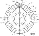
- the wheel 10 includes a rim 12 which is adapted to receive a tyre (not shown), and a disc 14 by which the wheel 10 can be attached to a hub of a vehicle.
- the wheel 10 also includes a connecting member 16 which is permanently attached to the rim 12, for example by welding, and to which the disc 14 is connectable.
- the wheel 10 has an axis of rotation A, which for the purposes of describing the wheel 10 is considered to be substantially horizontal. When used herein, the term 'axial' should be construed as substantially parallel to the axis A.
- the disc 14 shown in Figure 1 is generally 'square' with the corners of the square being truncated so as to provide a generally octagonal shape, having alternating long and short sides.
- the disc 14 may, alternatively, be substantially circular in shape.
- the disc 14 includes a plurality of substantially axially extending openings 18 through each of which a fastener 20 is receivable.
- the disc 14 includes eight openings 18, two provided at each truncated corner of the square. It will be appreciated that the disc may include more or fewer openings as appropriate.
- the openings 18 are spaced around the circumference of the disc 14, preferably with pairs of openings 18 spaced around the circumference of the disc 14, for example four pairs of openings 18 spaced at approximately 90° from one another. Again, it will be appreciated that any number of openings 18 may be provided in any appropriate arrangement.
- the disc 14 also includes a substantially axially extending locating opening 22a, which is positioned adjacent one of the openings 18, the purpose of which will be described in more detail below.
- the connecting member 16 is a substantially continuous ring which is attached around its circumference to the rim 12.
- the connecting member 16 may include a plurality of lugs which are circumferentially spaced around the circumference of the rim 12.
- the connecting member 16 includes a plurality of substantially axially extending openings or passages 24 in which a fastener 20 is receivable.
- the connecting member 16 also includes a substantially axially extending locating opening 26.
- the locating opening 26 is adjacent one of the openings 24. The distance between the centre of the locating opening 26 and the centre of the adjacent opening 24 is approximately 30mm. It will be appreciated that this distance may be altered as appropriate.
- Each fastener 20 includes a bolt 28, which is receivable through a respective opening 18 in the disc 14 and a respective opening 24 in the connecting member 16 to enable the fastener 20 to attach the disc 14 to the connecting member 16 of the rim 12.
- Each fastener 20 also includes a nut 30 and a washer 32.
- the wheel 10 also includes a spacer 40.
- the spacer 40 includes an opening 42 through which a fastener 20 is receivable.
- the opening 42 is approximately 16.5mm in diameter, but it will be appreciated that the dimensions of the opening 42 will depend upon the dimensions of the fastener 20 with which the spacer 40 is intended to co-operate.
- the spacer 40 also includes a locating member 44.
- the locating member 44 is a pin which extends through the spacer 40, so as to protrude from either side of the spacer 40.
- the locating member 44 acts as a centring pin, and in the present example takes the form of a dowel pin.
- the locating member 44 may be a different type of pin, for example a roll pin.
- the locating member 44 may be formed in an alternative way, provided the locating member 44 protrudes from both sides of the spacer 40.
- the locating member 44 has an overall length L of between approximately 23mm and approximately 27mm, and preferably approximately 25mm. It will be appreciated that other lengths L of the locating member 44 may be desirable and appropriate.
- the locating member 44 is substantially circular in cross-section and is approximately 10mm in diameter, but it will be appreciated that other shapes and sizes may be appropriate.
- the spacer 40 is substantially oval in cross-section.
- the spacer 40 has a depth D of approximately 15mm. It will be appreciated that other depths D of the spacer 40 may be desirable and appropriate.
- the centres of the opening 42 and the locating member 44 are spaced by a distance S, of approximately 30mm.
- the disc 14 is connected to the rim 12 by insertion of the bolt 24 of a fastener 20 through an opening 24 in the connecting member 16, through the opening 42 in the spacer 40 and through a corresponding opening 18 in the disc 14.
- the nut 30 and the washer 32 of the fastener 20 are attached to the bolt 24.
- the spacer 40 is thus sandwiched between the disc 14 and the connecting member 16 of the rim 12.
- the locating member 44 of the spacer 40 is received in the locating openings 22a and 26 of the disc 14 and the connecting member 16, respectively.
- spacers 50 which have only a central opening 52 for receiving a fastener 20, may be provided between the disc 14 and the connecting member 16 at other locations around the rim 12, such that the disc 14 is spaced substantially evenly from the rim 12 around the circumference of the rim 12.
- the disc 14 may be desirable to enable the disc 14 to be able to be fixed to the rim 12 in an alternative orientation, for example with the disc 14 rotated through 180° about a substantially vertical axis.
- the disc 14 is shown with a first face 14a adjacent the connecting member 16. If the disc 14 is rotated through 180° about a substantially vertical axis, into a second orientation relative to the rim 12, a second face 14b of the disc 14 will be positioned adjacent the connecting member 16.
- the locating member 44 of the spacer 40 is receivable in one of the locating openings 22a, 22b, dependent upon the orientation of the disc 14 relative to the rim 12.
- a second spacer 40 may be provided for use in connecting the disc 14 to the rim 12.
- this additional locating opening 26 is spaced approximately 90° around the connecting member 16 (or on an adjacent lug)
- Spacing the additional locating openings 22c, 22d at approximately 90° circumferentially around the disc 14 from the locating openings 22a, 22b means that it is not possible for a user to inadvertently rotate the disc 14 relative to the rim 12 during reassembly and still be able to correctly position and fix both spacers 40. Rotating the disc 14 through 90° relative to the rim 12 would mean that the locating member 44 of only one spacer 40 which was connected to the disc 14 would be positioned adjacent a locating opening 26 in the connecting member 16.
- a single locating opening 23 may be positioned substantially equidistantly between two openings 22 in the disc 14.
- the locating opening 26 in the connecting member 16 which corresponds with the locating opening 23 of the disc 14 for receiving the locating member 44 of the spacer 40 may be positioned substantially equidistantly between adjacent openings 24 in the connecting member 16 for receiving a fastener 20.
- the provision of the spacer 40 which acts as a centring device to accurately locate the disc 14 with respect to the rim 12 is advantageous in that it reduced the number of parts required to space the disc 14 from the rim 12 by an appropriate amount and to ensure appropriate rotational positioning of the disc 14 with respect to the rim 12, when reassembling the wheel 10.
- the locating spacer 40 ensures that there are only a discrete number of positions in which the disc 14 can be located 12 with respect to the rim 12, to minimise the change of the position of the maximum distance out of centre of the wheel 10 when reassembling the wheel 10. It is possible for at least eight track variations or 'offsets' to be provided by the wheel 10 including the spacer 40 as described above; i.e.
- the wheel 10 is described as having the or each spacer 40 positioned between the connecting member 16. However, if the or each spacer 40 were positioned adjacent the disc 14, but not between the disc 14 and the connecting member 16, this would provide a further eight offsets of the rim 12 relative to the hub of the vehicle.
- a further advantage of the present invention is that the locating member 44 of the spacer 40 is permanently attached to the spacer 40, thus reducing the risk of the locating member 44 being misplaced, for example during dismantling and reassembly of the wheel 10.
Landscapes
- Engineering & Computer Science (AREA)
- Mechanical Engineering (AREA)
- Tires In General (AREA)
- Connection Of Plates (AREA)
Priority Applications (1)
| Application Number | Priority Date | Filing Date | Title |
|---|---|---|---|
| PL15747196T PL3201008T3 (pl) | 2014-10-02 | 2015-07-30 | Koło |
Applications Claiming Priority (2)
| Application Number | Priority Date | Filing Date | Title |
|---|---|---|---|
| GB1417463.5A GB2531698A (en) | 2014-10-02 | 2014-10-02 | Wheel |
| PCT/GB2015/052200 WO2016051129A1 (en) | 2014-10-02 | 2015-07-30 | Wheel |
Publications (2)
| Publication Number | Publication Date |
|---|---|
| EP3201008A1 EP3201008A1 (en) | 2017-08-09 |
| EP3201008B1 true EP3201008B1 (en) | 2018-07-18 |
Family
ID=51946762
Family Applications (1)
| Application Number | Title | Priority Date | Filing Date |
|---|---|---|---|
| EP15747196.2A Active EP3201008B1 (en) | 2014-10-02 | 2015-07-30 | Wheel |
Country Status (9)
| Country | Link |
|---|---|
| US (1) | US10259261B2 (pl) |
| EP (1) | EP3201008B1 (pl) |
| CN (1) | CN107000470B (pl) |
| BR (1) | BR112017006746B8 (pl) |
| GB (1) | GB2531698A (pl) |
| PL (1) | PL3201008T3 (pl) |
| RU (1) | RU2684245C2 (pl) |
| TR (1) | TR201815409T4 (pl) |
| WO (1) | WO2016051129A1 (pl) |
Families Citing this family (1)
| Publication number | Priority date | Publication date | Assignee | Title |
|---|---|---|---|---|
| US11458759B2 (en) * | 2018-07-19 | 2022-10-04 | Gacw Incorporated | Wheel assembly including tread assemblies and related methods |
Family Cites Families (19)
| Publication number | Priority date | Publication date | Assignee | Title |
|---|---|---|---|---|
| US1639108A (en) * | 1918-02-28 | 1927-08-16 | Motor Wheel Corp | Rim fastener for vehicle wheels |
| US2228488A (en) * | 1938-09-30 | 1941-01-14 | Int Harvester Co | Rim mounting |
| US2237481A (en) * | 1940-02-13 | 1941-04-08 | Ferro Casimiro | Vehicle wheel |
| GB1390640A (en) * | 1972-12-07 | 1975-04-16 | Gkn Sankey Ltd | Variable track wheels |
| GB2058686B (en) * | 1979-09-18 | 1983-11-30 | Gkn Sankey Ltd | Variable-track wheels |
| US4643484A (en) * | 1980-09-16 | 1987-02-17 | Karl Moeller Nagbol | Manually adjustable wheels |
| JPS59124703A (ja) * | 1982-12-30 | 1984-07-18 | Alps Electric Co Ltd | コイル体のインダクタンス調整方法 |
| JPS59124703U (ja) | 1983-02-10 | 1984-08-22 | 井関農機株式会社 | トレツドの変更可能な車輪 |
| GB8430403D0 (en) * | 1984-12-01 | 1985-01-09 | Gkn Sankey Ltd | Tractor wheels |
| GB9524952D0 (en) * | 1995-12-06 | 1996-02-07 | Gkn Sankey Ltd | Wheels |
| US6027176A (en) * | 1997-10-14 | 2000-02-22 | Titan International, Inc. | Wheel |
| IT249854Y1 (it) * | 2000-07-19 | 2003-06-05 | Titan Italia S P A | Ruota a carreggiata variabile con dispositivi di posizionamentoreciproco di cerchione e disco |
| IT250370Y1 (it) * | 2000-09-06 | 2003-09-10 | Titan Italia S P A | Ruota a carreggiata variabile con sistema di centraggio a spina |
| JP4188029B2 (ja) * | 2002-08-23 | 2008-11-26 | 横浜ゴム株式会社 | タイヤ用ホイール |
| US20050102208A1 (en) * | 2003-11-10 | 2005-05-12 | Gudgeon Jerome E. | Systems and methods for tracking financial securities transactions |
| DE102004052816A1 (de) * | 2004-10-29 | 2006-05-04 | Mefro Räderwerk Ronneburg GmbH | Spurverstellrad und Verfahren zur Herstellung eines Spurverstellrads |
| NL1036570C2 (nl) * | 2009-02-13 | 2010-08-16 | Gruva Techniek B V | Wiel voor landbouwvoertuigen met variabele offset, tussenstukmodule voor een dergelijk wiel. |
| ITMI20111857A1 (it) * | 2011-10-12 | 2013-04-13 | Freni Brembo Spa | Assieme di flangia di collegamento ad un cerchio ruota e disco di frenatura |
| DK2607097T3 (en) * | 2011-12-20 | 2016-01-25 | Titan Italia S P A | Wheels with variable track |
-
2014
- 2014-10-02 GB GB1417463.5A patent/GB2531698A/en not_active Withdrawn
-
2015
- 2015-07-30 EP EP15747196.2A patent/EP3201008B1/en active Active
- 2015-07-30 BR BR112017006746A patent/BR112017006746B8/pt active IP Right Grant
- 2015-07-30 WO PCT/GB2015/052200 patent/WO2016051129A1/en not_active Ceased
- 2015-07-30 PL PL15747196T patent/PL3201008T3/pl unknown
- 2015-07-30 CN CN201580053815.9A patent/CN107000470B/zh active Active
- 2015-07-30 US US15/514,877 patent/US10259261B2/en active Active
- 2015-07-30 TR TR2018/15409T patent/TR201815409T4/tr unknown
- 2015-07-30 RU RU2017115137A patent/RU2684245C2/ru active
Also Published As
| Publication number | Publication date |
|---|---|
| GB201417463D0 (en) | 2014-11-19 |
| BR112017006746B8 (pt) | 2023-04-25 |
| TR201815409T4 (tr) | 2018-11-21 |
| GB2531698A (en) | 2016-05-04 |
| CN107000470B (zh) | 2019-09-03 |
| EP3201008A1 (en) | 2017-08-09 |
| RU2017115137A3 (pl) | 2019-01-31 |
| BR112017006746B1 (pt) | 2021-04-20 |
| CN107000470A (zh) | 2017-08-01 |
| US10259261B2 (en) | 2019-04-16 |
| RU2684245C2 (ru) | 2019-04-04 |
| RU2017115137A (ru) | 2018-11-02 |
| BR112017006746A2 (pt) | 2019-03-06 |
| PL3201008T3 (pl) | 2019-02-28 |
| WO2016051129A1 (en) | 2016-04-07 |
| US20170239983A1 (en) | 2017-08-24 |
Similar Documents
| Publication | Publication Date | Title |
|---|---|---|
| EP2868489B1 (en) | Omni-directional wheel and omni-directional vehicle including the same | |
| US9505263B2 (en) | Wheel | |
| US20130140874A1 (en) | Wheel for automobile | |
| JP2018176990A5 (pl) | ||
| EP3023658B1 (en) | Two piece annular protective cover with a sensor unit for an axle-box-bearing unit of a rail vehicle and axle-box-bearing unit with the protective cover | |
| EP4242011A3 (en) | Vehicle wheel disc, vehicle wheel including such a wheel disc | |
| JP6661304B2 (ja) | 全方向移動車両用車輪 | |
| WO2010088912A1 (en) | Set of twin wheels | |
| EP3201008B1 (en) | Wheel | |
| EP3177465B1 (en) | Wheel for industrial and commercial vehicles | |
| US5938291A (en) | Wheels | |
| JP2014218151A (ja) | ホイール取付構造 | |
| US20140339045A1 (en) | Reduced drag clutch plate | |
| US2521260A (en) | Wheel | |
| EP1174285A2 (en) | A varying-track wheel with devices for mutual-positioning of the rim and disc | |
| EP3135573A3 (en) | A wheel for straddled vehicles and a straddled vehicle | |
| CN202900948U (zh) | 一种汽车车轮螺母夹 | |
| CN110087895B (zh) | 用于形成和组装车辆车轮的方法 | |
| JP2014181786A (ja) | ディスクブレーキ | |
| US20130062929A1 (en) | Hub unit | |
| KR20170138619A (ko) | 스타일드 휠 | |
| JP2001105802A (ja) | 車輪ホイール及びそれを使用したゴム車輪 | |
| KR20110093195A (ko) | 자전거용 휠 | |
| MY156644A (en) | Dual wheels with common hub adapter | |
| KR20160087701A (ko) | 휠 허브 및 이를 포함하는 휠 베어링 조립체 |
Legal Events
| Date | Code | Title | Description |
|---|---|---|---|
| PUAI | Public reference made under article 153(3) epc to a published international application that has entered the european phase |
Free format text: ORIGINAL CODE: 0009012 |
|
| 17P | Request for examination filed |
Effective date: 20170320 |
|
| AK | Designated contracting states |
Kind code of ref document: A1 Designated state(s): AL AT BE BG CH CY CZ DE DK EE ES FI FR GB GR HR HU IE IS IT LI LT LU LV MC MK MT NL NO PL PT RO RS SE SI SK SM TR |
|
| AX | Request for extension of the european patent |
Extension state: BA ME |
|
| DAV | Request for validation of the european patent (deleted) | ||
| DAX | Request for extension of the european patent (deleted) | ||
| GRAP | Despatch of communication of intention to grant a patent |
Free format text: ORIGINAL CODE: EPIDOSNIGR1 |
|
| RIC1 | Information provided on ipc code assigned before grant |
Ipc: B60B 23/06 20060101ALI20180112BHEP Ipc: B60B 25/04 20060101ALI20180112BHEP Ipc: B60B 23/12 20060101ALI20180112BHEP Ipc: B60B 3/04 20060101AFI20180112BHEP Ipc: B60B 23/10 20060101ALI20180112BHEP |
|
| INTG | Intention to grant announced |
Effective date: 20180202 |
|
| GRAS | Grant fee paid |
Free format text: ORIGINAL CODE: EPIDOSNIGR3 |
|
| GRAA | (expected) grant |
Free format text: ORIGINAL CODE: 0009210 |
|
| AK | Designated contracting states |
Kind code of ref document: B1 Designated state(s): AL AT BE BG CH CY CZ DE DK EE ES FI FR GB GR HR HU IE IS IT LI LT LU LV MC MK MT NL NO PL PT RO RS SE SI SK SM TR |
|
| RAP1 | Party data changed (applicant data changed or rights of an application transferred) |
Owner name: GKN WHEELS LIMITED |
|
| REG | Reference to a national code |
Ref country code: GB Ref legal event code: FG4D |
|
| REG | Reference to a national code |
Ref country code: CH Ref legal event code: EP |
|
| REG | Reference to a national code |
Ref country code: IE Ref legal event code: FG4D |
|
| REG | Reference to a national code |
Ref country code: AT Ref legal event code: REF Ref document number: 1018940 Country of ref document: AT Kind code of ref document: T Effective date: 20180815 |
|
| REG | Reference to a national code |
Ref country code: DE Ref legal event code: R096 Ref document number: 602015013775 Country of ref document: DE |
|
| REG | Reference to a national code |
Ref country code: FR Ref legal event code: PLFP Year of fee payment: 4 |
|
| REG | Reference to a national code |
Ref country code: SE Ref legal event code: TRGR |
|
| REG | Reference to a national code |
Ref country code: NL Ref legal event code: MP Effective date: 20180718 |
|
| REG | Reference to a national code |
Ref country code: LT Ref legal event code: MG4D |
|
| REG | Reference to a national code |
Ref country code: AT Ref legal event code: MK05 Ref document number: 1018940 Country of ref document: AT Kind code of ref document: T Effective date: 20180718 |
|
| PG25 | Lapsed in a contracting state [announced via postgrant information from national office to epo] |
Ref country code: NL Free format text: LAPSE BECAUSE OF FAILURE TO SUBMIT A TRANSLATION OF THE DESCRIPTION OR TO PAY THE FEE WITHIN THE PRESCRIBED TIME-LIMIT Effective date: 20180718 |
|
| PG25 | Lapsed in a contracting state [announced via postgrant information from national office to epo] |
Ref country code: NO Free format text: LAPSE BECAUSE OF FAILURE TO SUBMIT A TRANSLATION OF THE DESCRIPTION OR TO PAY THE FEE WITHIN THE PRESCRIBED TIME-LIMIT Effective date: 20181018 Ref country code: BG Free format text: LAPSE BECAUSE OF FAILURE TO SUBMIT A TRANSLATION OF THE DESCRIPTION OR TO PAY THE FEE WITHIN THE PRESCRIBED TIME-LIMIT Effective date: 20181018 Ref country code: GR Free format text: LAPSE BECAUSE OF FAILURE TO SUBMIT A TRANSLATION OF THE DESCRIPTION OR TO PAY THE FEE WITHIN THE PRESCRIBED TIME-LIMIT Effective date: 20181019 Ref country code: LT Free format text: LAPSE BECAUSE OF FAILURE TO SUBMIT A TRANSLATION OF THE DESCRIPTION OR TO PAY THE FEE WITHIN THE PRESCRIBED TIME-LIMIT Effective date: 20180718 Ref country code: FI Free format text: LAPSE BECAUSE OF FAILURE TO SUBMIT A TRANSLATION OF THE DESCRIPTION OR TO PAY THE FEE WITHIN THE PRESCRIBED TIME-LIMIT Effective date: 20180718 Ref country code: RS Free format text: LAPSE BECAUSE OF FAILURE TO SUBMIT A TRANSLATION OF THE DESCRIPTION OR TO PAY THE FEE WITHIN THE PRESCRIBED TIME-LIMIT Effective date: 20180718 Ref country code: AT Free format text: LAPSE BECAUSE OF FAILURE TO SUBMIT A TRANSLATION OF THE DESCRIPTION OR TO PAY THE FEE WITHIN THE PRESCRIBED TIME-LIMIT Effective date: 20180718 Ref country code: IS Free format text: LAPSE BECAUSE OF FAILURE TO SUBMIT A TRANSLATION OF THE DESCRIPTION OR TO PAY THE FEE WITHIN THE PRESCRIBED TIME-LIMIT Effective date: 20181118 |
|
| PG25 | Lapsed in a contracting state [announced via postgrant information from national office to epo] |
Ref country code: HR Free format text: LAPSE BECAUSE OF FAILURE TO SUBMIT A TRANSLATION OF THE DESCRIPTION OR TO PAY THE FEE WITHIN THE PRESCRIBED TIME-LIMIT Effective date: 20180718 Ref country code: AL Free format text: LAPSE BECAUSE OF FAILURE TO SUBMIT A TRANSLATION OF THE DESCRIPTION OR TO PAY THE FEE WITHIN THE PRESCRIBED TIME-LIMIT Effective date: 20180718 |
|
| REG | Reference to a national code |
Ref country code: CH Ref legal event code: PL |
|
| PG25 | Lapsed in a contracting state [announced via postgrant information from national office to epo] |
Ref country code: LU Free format text: LAPSE BECAUSE OF NON-PAYMENT OF DUE FEES Effective date: 20180730 |
|
| REG | Reference to a national code |
Ref country code: BE Ref legal event code: MM Effective date: 20180731 |
|
| REG | Reference to a national code |
Ref country code: DE Ref legal event code: R097 Ref document number: 602015013775 Country of ref document: DE |
|
| PG25 | Lapsed in a contracting state [announced via postgrant information from national office to epo] |
Ref country code: CH Free format text: LAPSE BECAUSE OF NON-PAYMENT OF DUE FEES Effective date: 20180731 Ref country code: CZ Free format text: LAPSE BECAUSE OF FAILURE TO SUBMIT A TRANSLATION OF THE DESCRIPTION OR TO PAY THE FEE WITHIN THE PRESCRIBED TIME-LIMIT Effective date: 20180718 Ref country code: RO Free format text: LAPSE BECAUSE OF FAILURE TO SUBMIT A TRANSLATION OF THE DESCRIPTION OR TO PAY THE FEE WITHIN THE PRESCRIBED TIME-LIMIT Effective date: 20180718 Ref country code: EE Free format text: LAPSE BECAUSE OF FAILURE TO SUBMIT A TRANSLATION OF THE DESCRIPTION OR TO PAY THE FEE WITHIN THE PRESCRIBED TIME-LIMIT Effective date: 20180718 Ref country code: LI Free format text: LAPSE BECAUSE OF NON-PAYMENT OF DUE FEES Effective date: 20180731 Ref country code: MC Free format text: LAPSE BECAUSE OF FAILURE TO SUBMIT A TRANSLATION OF THE DESCRIPTION OR TO PAY THE FEE WITHIN THE PRESCRIBED TIME-LIMIT Effective date: 20180718 Ref country code: LV Free format text: LAPSE BECAUSE OF NON-PAYMENT OF DUE FEES Effective date: 20180730 Ref country code: ES Free format text: LAPSE BECAUSE OF FAILURE TO SUBMIT A TRANSLATION OF THE DESCRIPTION OR TO PAY THE FEE WITHIN THE PRESCRIBED TIME-LIMIT Effective date: 20180718 |
|
| REG | Reference to a national code |
Ref country code: IE Ref legal event code: MM4A |
|
| PLBE | No opposition filed within time limit |
Free format text: ORIGINAL CODE: 0009261 |
|
| STAA | Information on the status of an ep patent application or granted ep patent |
Free format text: STATUS: NO OPPOSITION FILED WITHIN TIME LIMIT |
|
| PG25 | Lapsed in a contracting state [announced via postgrant information from national office to epo] |
Ref country code: SK Free format text: LAPSE BECAUSE OF FAILURE TO SUBMIT A TRANSLATION OF THE DESCRIPTION OR TO PAY THE FEE WITHIN THE PRESCRIBED TIME-LIMIT Effective date: 20180718 Ref country code: DK Free format text: LAPSE BECAUSE OF FAILURE TO SUBMIT A TRANSLATION OF THE DESCRIPTION OR TO PAY THE FEE WITHIN THE PRESCRIBED TIME-LIMIT Effective date: 20180718 Ref country code: BE Free format text: LAPSE BECAUSE OF NON-PAYMENT OF DUE FEES Effective date: 20180731 Ref country code: SM Free format text: LAPSE BECAUSE OF FAILURE TO SUBMIT A TRANSLATION OF THE DESCRIPTION OR TO PAY THE FEE WITHIN THE PRESCRIBED TIME-LIMIT Effective date: 20180718 |
|
| 26N | No opposition filed |
Effective date: 20190423 |
|
| PG25 | Lapsed in a contracting state [announced via postgrant information from national office to epo] |
Ref country code: IE Free format text: LAPSE BECAUSE OF NON-PAYMENT OF DUE FEES Effective date: 20180730 |
|
| PG25 | Lapsed in a contracting state [announced via postgrant information from national office to epo] |
Ref country code: SI Free format text: LAPSE BECAUSE OF FAILURE TO SUBMIT A TRANSLATION OF THE DESCRIPTION OR TO PAY THE FEE WITHIN THE PRESCRIBED TIME-LIMIT Effective date: 20180718 |
|
| PG25 | Lapsed in a contracting state [announced via postgrant information from national office to epo] |
Ref country code: MT Free format text: LAPSE BECAUSE OF NON-PAYMENT OF DUE FEES Effective date: 20180730 |
|
| PG25 | Lapsed in a contracting state [announced via postgrant information from national office to epo] |
Ref country code: PT Free format text: LAPSE BECAUSE OF FAILURE TO SUBMIT A TRANSLATION OF THE DESCRIPTION OR TO PAY THE FEE WITHIN THE PRESCRIBED TIME-LIMIT Effective date: 20180718 |
|
| PG25 | Lapsed in a contracting state [announced via postgrant information from national office to epo] |
Ref country code: MK Free format text: LAPSE BECAUSE OF NON-PAYMENT OF DUE FEES Effective date: 20180718 Ref country code: HU Free format text: LAPSE BECAUSE OF FAILURE TO SUBMIT A TRANSLATION OF THE DESCRIPTION OR TO PAY THE FEE WITHIN THE PRESCRIBED TIME-LIMIT; INVALID AB INITIO Effective date: 20150730 Ref country code: CY Free format text: LAPSE BECAUSE OF FAILURE TO SUBMIT A TRANSLATION OF THE DESCRIPTION OR TO PAY THE FEE WITHIN THE PRESCRIBED TIME-LIMIT Effective date: 20180718 |
|
| REG | Reference to a national code |
Ref country code: DE Ref legal event code: R081 Ref document number: 602015013775 Country of ref document: DE Owner name: MOVEERO LTD., GB Free format text: FORMER OWNER: GKN WHEELS LIMITED, REDDITCH, WORCESTERSHIRE B98 0TL, GB |
|
| P01 | Opt-out of the competence of the unified patent court (upc) registered |
Effective date: 20230613 |
|
| PGFP | Annual fee paid to national office [announced via postgrant information from national office to epo] |
Ref country code: GB Payment date: 20250619 Year of fee payment: 11 |
|
| PGFP | Annual fee paid to national office [announced via postgrant information from national office to epo] |
Ref country code: DE Payment date: 20250722 Year of fee payment: 11 |
|
| PGFP | Annual fee paid to national office [announced via postgrant information from national office to epo] |
Ref country code: TR Payment date: 20250722 Year of fee payment: 11 Ref country code: IT Payment date: 20250721 Year of fee payment: 11 Ref country code: PL Payment date: 20250717 Year of fee payment: 11 |
|
| PGFP | Annual fee paid to national office [announced via postgrant information from national office to epo] |
Ref country code: FR Payment date: 20250725 Year of fee payment: 11 |
|
| PGFP | Annual fee paid to national office [announced via postgrant information from national office to epo] |
Ref country code: SE Payment date: 20250722 Year of fee payment: 11 |
|
| PGFP | Annual fee paid to national office [announced via postgrant information from national office to epo] |
Ref country code: LV Payment date: 20250714 Year of fee payment: 11 |