EP3200221A1 - Reinigungsvorrichtung und reinigungsverfahren - Google Patents
Reinigungsvorrichtung und reinigungsverfahren Download PDFInfo
- Publication number
- EP3200221A1 EP3200221A1 EP15845065.0A EP15845065A EP3200221A1 EP 3200221 A1 EP3200221 A1 EP 3200221A1 EP 15845065 A EP15845065 A EP 15845065A EP 3200221 A1 EP3200221 A1 EP 3200221A1
- Authority
- EP
- European Patent Office
- Prior art keywords
- purging
- containers
- container
- local vehicle
- shelf
- Prior art date
- Legal status (The legal status is an assumption and is not a legal conclusion. Google has not performed a legal analysis and makes no representation as to the accuracy of the status listed.)
- Granted
Links
Images



Classifications
-
- H—ELECTRICITY
- H10—SEMICONDUCTOR DEVICES; ELECTRIC SOLID-STATE DEVICES NOT OTHERWISE PROVIDED FOR
- H10P—GENERIC PROCESSES OR APPARATUS FOR THE MANUFACTURE OR TREATMENT OF DEVICES COVERED BY CLASS H10
- H10P72/00—Handling or holding of wafers, substrates or devices during manufacture or treatment thereof
- H10P72/30—Handling or holding of wafers, substrates or devices during manufacture or treatment thereof for conveying, e.g. between different workstations
- H10P72/34—Handling or holding of wafers, substrates or devices during manufacture or treatment thereof for conveying, e.g. between different workstations the wafers being stored in a carrier, involving loading and unloading
- H10P72/3411—Handling or holding of wafers, substrates or devices during manufacture or treatment thereof for conveying, e.g. between different workstations the wafers being stored in a carrier, involving loading and unloading involving loading and unloading of wafers
-
- B—PERFORMING OPERATIONS; TRANSPORTING
- B08—CLEANING
- B08B—CLEANING IN GENERAL; PREVENTION OF FOULING IN GENERAL
- B08B9/00—Cleaning hollow articles by methods or apparatus specially adapted thereto
- B08B9/08—Cleaning containers, e.g. tanks
-
- H—ELECTRICITY
- H10—SEMICONDUCTOR DEVICES; ELECTRIC SOLID-STATE DEVICES NOT OTHERWISE PROVIDED FOR
- H10P—GENERIC PROCESSES OR APPARATUS FOR THE MANUFACTURE OR TREATMENT OF DEVICES COVERED BY CLASS H10
- H10P72/00—Handling or holding of wafers, substrates or devices during manufacture or treatment thereof
- H10P72/10—Handling or holding of wafers, substrates or devices during manufacture or treatment thereof using carriers specially adapted therefor, e.g. front opening unified pods [FOUP]
- H10P72/19—Handling or holding of wafers, substrates or devices during manufacture or treatment thereof using carriers specially adapted therefor, e.g. front opening unified pods [FOUP] closed carriers
- H10P72/1924—Handling or holding of wafers, substrates or devices during manufacture or treatment thereof using carriers specially adapted therefor, e.g. front opening unified pods [FOUP] closed carriers characterised by atmosphere control
-
- H—ELECTRICITY
- H10—SEMICONDUCTOR DEVICES; ELECTRIC SOLID-STATE DEVICES NOT OTHERWISE PROVIDED FOR
- H10P—GENERIC PROCESSES OR APPARATUS FOR THE MANUFACTURE OR TREATMENT OF DEVICES COVERED BY CLASS H10
- H10P72/00—Handling or holding of wafers, substrates or devices during manufacture or treatment thereof
- H10P72/30—Handling or holding of wafers, substrates or devices during manufacture or treatment thereof for conveying, e.g. between different workstations
- H10P72/32—Handling or holding of wafers, substrates or devices during manufacture or treatment thereof for conveying, e.g. between different workstations between different workstations
- H10P72/3202—Mechanical details, e.g. rollers or belts
-
- H—ELECTRICITY
- H10—SEMICONDUCTOR DEVICES; ELECTRIC SOLID-STATE DEVICES NOT OTHERWISE PROVIDED FOR
- H10P—GENERIC PROCESSES OR APPARATUS FOR THE MANUFACTURE OR TREATMENT OF DEVICES COVERED BY CLASS H10
- H10P72/00—Handling or holding of wafers, substrates or devices during manufacture or treatment thereof
- H10P72/30—Handling or holding of wafers, substrates or devices during manufacture or treatment thereof for conveying, e.g. between different workstations
- H10P72/32—Handling or holding of wafers, substrates or devices during manufacture or treatment thereof for conveying, e.g. between different workstations between different workstations
- H10P72/3214—Handling or holding of wafers, substrates or devices during manufacture or treatment thereof for conveying, e.g. between different workstations between different workstations by means of a cart or a vehicle
-
- H—ELECTRICITY
- H10—SEMICONDUCTOR DEVICES; ELECTRIC SOLID-STATE DEVICES NOT OTHERWISE PROVIDED FOR
- H10P—GENERIC PROCESSES OR APPARATUS FOR THE MANUFACTURE OR TREATMENT OF DEVICES COVERED BY CLASS H10
- H10P72/00—Handling or holding of wafers, substrates or devices during manufacture or treatment thereof
- H10P72/30—Handling or holding of wafers, substrates or devices during manufacture or treatment thereof for conveying, e.g. between different workstations
- H10P72/32—Handling or holding of wafers, substrates or devices during manufacture or treatment thereof for conveying, e.g. between different workstations between different workstations
- H10P72/3218—Conveying cassettes, containers or carriers
-
- H—ELECTRICITY
- H10—SEMICONDUCTOR DEVICES; ELECTRIC SOLID-STATE DEVICES NOT OTHERWISE PROVIDED FOR
- H10P—GENERIC PROCESSES OR APPARATUS FOR THE MANUFACTURE OR TREATMENT OF DEVICES COVERED BY CLASS H10
- H10P72/00—Handling or holding of wafers, substrates or devices during manufacture or treatment thereof
- H10P72/30—Handling or holding of wafers, substrates or devices during manufacture or treatment thereof for conveying, e.g. between different workstations
- H10P72/32—Handling or holding of wafers, substrates or devices during manufacture or treatment thereof for conveying, e.g. between different workstations between different workstations
- H10P72/3221—Overhead conveying
-
- H—ELECTRICITY
- H10—SEMICONDUCTOR DEVICES; ELECTRIC SOLID-STATE DEVICES NOT OTHERWISE PROVIDED FOR
- H10P—GENERIC PROCESSES OR APPARATUS FOR THE MANUFACTURE OR TREATMENT OF DEVICES COVERED BY CLASS H10
- H10P72/00—Handling or holding of wafers, substrates or devices during manufacture or treatment thereof
- H10P72/30—Handling or holding of wafers, substrates or devices during manufacture or treatment thereof for conveying, e.g. between different workstations
- H10P72/32—Handling or holding of wafers, substrates or devices during manufacture or treatment thereof for conveying, e.g. between different workstations between different workstations
- H10P72/3222—Loading to or unloading from a conveyor
-
- H—ELECTRICITY
- H10—SEMICONDUCTOR DEVICES; ELECTRIC SOLID-STATE DEVICES NOT OTHERWISE PROVIDED FOR
- H10P—GENERIC PROCESSES OR APPARATUS FOR THE MANUFACTURE OR TREATMENT OF DEVICES COVERED BY CLASS H10
- H10P72/00—Handling or holding of wafers, substrates or devices during manufacture or treatment thereof
- H10P72/30—Handling or holding of wafers, substrates or devices during manufacture or treatment thereof for conveying, e.g. between different workstations
- H10P72/34—Handling or holding of wafers, substrates or devices during manufacture or treatment thereof for conveying, e.g. between different workstations the wafers being stored in a carrier, involving loading and unloading
- H10P72/3402—Mechanical parts of transfer devices
-
- H—ELECTRICITY
- H10—SEMICONDUCTOR DEVICES; ELECTRIC SOLID-STATE DEVICES NOT OTHERWISE PROVIDED FOR
- H10W—GENERIC PACKAGES, INTERCONNECTIONS, CONNECTORS OR OTHER CONSTRUCTIONAL DETAILS OF DEVICES COVERED BY CLASS H10
- H10W76/00—Containers; Fillings or auxiliary members therefor; Seals
- H10W76/01—Manufacture or treatment
- H10W76/05—Providing fillings in containers, e.g. gas filling
-
- G—PHYSICS
- G05—CONTROLLING; REGULATING
- G05D—SYSTEMS FOR CONTROLLING OR REGULATING NON-ELECTRIC VARIABLES
- G05D7/00—Control of flow
- G05D7/06—Control of flow characterised by the use of electric means
-
- H—ELECTRICITY
- H10—SEMICONDUCTOR DEVICES; ELECTRIC SOLID-STATE DEVICES NOT OTHERWISE PROVIDED FOR
- H10P—GENERIC PROCESSES OR APPARATUS FOR THE MANUFACTURE OR TREATMENT OF DEVICES COVERED BY CLASS H10
- H10P72/00—Handling or holding of wafers, substrates or devices during manufacture or treatment thereof
- H10P72/04—Apparatus for manufacture or treatment
- H10P72/0402—Apparatus for fluid treatment
-
- H—ELECTRICITY
- H10—SEMICONDUCTOR DEVICES; ELECTRIC SOLID-STATE DEVICES NOT OTHERWISE PROVIDED FOR
- H10P—GENERIC PROCESSES OR APPARATUS FOR THE MANUFACTURE OR TREATMENT OF DEVICES COVERED BY CLASS H10
- H10P72/00—Handling or holding of wafers, substrates or devices during manufacture or treatment thereof
- H10P72/30—Handling or holding of wafers, substrates or devices during manufacture or treatment thereof for conveying, e.g. between different workstations
- H10P72/34—Handling or holding of wafers, substrates or devices during manufacture or treatment thereof for conveying, e.g. between different workstations the wafers being stored in a carrier, involving loading and unloading
- H10P72/3404—Storage means
Definitions
- the invention relates to the purging of containers accommodating semiconductor wafers, etc.
- cassettes for accommodating semiconductor wafers are transferred by an overhead transfer system between load ports of processing equipment.
- the applicant has proposed an apparatus comprising a local vehicle, its travelling rail, and a buffer between the load ports and the travelling rail for the overhead transfer vehicles (Patent Document 1: JP5229363B ).
- the cassettes may vertically pass through a gap between a pair of travelling rails for the local vehicle, and the buffer under the travelling rails for the local vehicle allows both the overhead transfer vehicles and the local vehicle to access the cassette.
- Patent Document 1 JP5229363B
- the object of the invention is to provide an apparatus for purging containers in the vicinity of a transfer place such as a load port.
- a purging apparatus purges containers between overhead transfer vehicles and at least a container transfer place to or from which the containers are transferred, and comprises:
- a purging method uses a purging apparatus comprising: at least a local vehicle configured to travel and provided with a hoist for raising and lowering containers; at least a travelling rail for the local vehicle, provided below a travelling rail for overhead transfer vehicles and above a container transfer place to or from which containers are transferred; a purging table configured to support the containers, provided below the travelling rail for the local vehicle so as not to block a portion over the container transfer place; and a purging gas feeding device for feeding a purging gas into the containers supported on the purging table, and comprises: placing the containers temporarily on the purging table between the overhead transfer vehicles and the container transfer place, and purging the containers with the purging gas by the purging gas feeding device.
- containers waiting for transfer by the overhead transfer vehicles are purged in the vicinity of a container transfer place.
- Articles to be accommodated within the containers are semiconductor wafers, foods, medicines, and the like, and purging of containers after the processing of articles reduces problems such as contamination and oxidation of the articles during the wait time for the next processing or the like.
- the surface of the articles are made clean in advance.
- the hoist in the claims corresponds to raising and lowering devices and the like in the embodiments
- the container transfer place corresponds to load ports of processing equipment and the like in the embodiments.
- the purging table corresponds to slide shelves and fixed shelves and the like in the embodiments. In this specification, any description concerning the purging apparatus are equally applicable to the purging method.
- the purging table is provided with at least a slide shelf configured to slide between a position different from the portion over the container transfer place and the portion.
- the overhead transfer vehicles may transfer the containers between the container transfer place without travelling, and the sliding direction is for example perpendicular to the travelling direction of the local vehicle in a horizontal plane.
- the purging table is further provided with at least a fixed shelf other than the slide shelf, and the controller of the purging apparatus is configured and programmed to control the local vehicle and to select a shelf to support a container from the slide shelf and the fixed shelf in such a way that a container to be transferred to the container transfer place is preferentially purged in the slide shelf to the other containers.
- the capacity of the purging table is increased by the fixed shelf, and containers to be transferred to the container transfer place are more promptly transferred.
- the purging apparatus is provided in a ceiling space of a cleanroom and configured to receive the purging gas from a ceiling of the cleanroom. Since installed in the ceiling space, the purging apparatus does not occupy a floor space, and since pipes for the purging gas such as N2 and dry clean air are already often provided in the ceiling, supply of the purging gas is made easy.
- the containers are cassettes for accommodating semiconductor wafers, and the container transfer place is a load port of semiconductor processing equipment.
- the containers are purged before or after the containers are transferred to a load port for processing semiconductor wafers by the processing equipment.
- the purging table is provided with a fixed part at a position different from the portion over the container transfer place
- the slide shelf is configured to slide between a portion over the fixed part and the portion over the container transfer place
- the purging gas feeding device comprises at least a feeding nozzle provided on the slide shelf and for feeding the purging gas into the containers; and a pipe for feeding the purging gas to the feeding nozzle from the fixed part; the pipe is provided with a bendable portion capable of being bent; and a cable guide supporting the bendable portion bendably is provided between the slide shelf and the fixed part.
- the purging gas is easily supplied to the feeding nozzle on the slide shelf.
- the slide shelf is provided with a load sensor for detecting a load from a container
- the purging gas feeding device is configured to feed the purging gas through the feeding nozzle, when the load sensor detects a load from a container, and at least a power line and at least a signal line of the load sensor are supported by the cable guide together with the pipe.
- the purging gas is supplied when the load sensor detects the load from a container, and therefore, the purging gas is effectively supplied. Further, the cable guide supports not only the pipe but also the power line and the signal line.
- FIGS. 1-6 show the embodiment of the invention and its modifications.
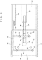
- FIGS. 1 and 2 show the purging apparatus 20 according to the embodiment, and surrounding processing equipment 2 and an overhead transfer system 8.
- the processing equipment 2 is provided with load ports 4 which are an example of transfer places of cassettes 6.
- the processing equipment 2 is not limited to processing apparatuses; it may be an inspection equipment, and the like, and it may be replaced by a storage of empty cassettes or the like.
- the cassettes 6 may accommodate semiconductor wafers for products, process control wafers, or wafers for inspection purpose and may be empty cassettes. Further, they may accommodate reticles or the like instead of the semiconductor wafers.
- the cassettes 6 are FOUPs (Front Opening Unified Pods).
- the overhead transfer system 8 is provided with travelling rail 10 and overhead transfer vehicles 12.
- the travelling rail 10 passes just over the load ports 4 and is supported from a ceiling of a cleanroom or the like.
- the overhead transfer vehicles 12 are provided with a lateral movement device and a rotation device 14, and they move a raising and lowering device 15 laterally and also rotate it.
- the raising and lowering device 15 raises and lowers an elevation platform 16 capable of chucking the cassettes 6.
- the purging apparatus 20 is provided with at least a local vehicle 22 and a travelling rail 24 for them.
- the cassettes may pass vertically through an open space 26 between a pair of rails of the travelling rail 24.
- Under the travelling rail 24 is a buffer with a purging function.
- the buffer includes slide shelves 28 just over the load ports 4 and capable of sliding them along the lateral direction in FIG. 1 (the horizontal and perpendicular direction to the longitudinal direction of the travelling rail 24) and includes further, for example, two fixed shelves 30 at positions remote from the load ports 4 in a plan view.
- Under a slide shelf 28 is a fixed part 29 that accommodates a slide mechanism of the shelf and elements for purging, and the fixed shelves have purging elements (not shown) at their bottoms.
- the purging apparatus 20 is attached by support rods 31 to the travelling rail 10 of the overhead transfer vehicles 12, however, it may be supported from the ground. Necessary gases and electricity for purging, and the like, are supplied through the support rod 31 or the like from the ceiling of the cleanroom, however, they may be supplied from the ground.
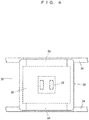
- FIG. 3 shows the slide shelf 28, and the slide shelf 28 advances and retracts along a guide 32 relative to the fixed part 29.
- the mechanism for the sliding is arbitrary, and, for example, a middle part 38 is fixed to a piston 36 engaged in a cylinder 34 which is driven by N2 gas or the like, so that the middle part 38 advances and retracts.
- double stroke mechanism (not shown) makes a top part 40 advance and retract with a double stroke of the piston 36, and a plate 33 is fixed to the top plate 40 for placing the cassettes.
- Three coupling pins 33 are provided on the plate 33 so that they form a triangle and they guide the bottom faces of the cassettes, a seating sensor 44 detects presence or absence of a cassette, and a load sensor 45 detects presence or absence of a load from a cassette.
- a seating sensor 44 detects presence or absence of a cassette
- a load sensor 45 detects presence or absence of a load from a cassette.
- On the plate 33 are for example two feeding nozzles 46, 46 and for example two exhaust nozzles 48, 48, , a pipe 50 feeds a purging gas such as N2, and a pipe 52 discharges exhaust gas from a cassette. Bellows making parts of the pipes 50, 52 are attached to a cable guide 54 and they bend together with power and signal lines of sensors 44, 45. Note that the exhaust pipe 48 and the pipe 52 may be omitted.
- the pipes 50, 52 may have other bendable portions bendable and may be supported by the cable guide 54 instead of the bellows.
- the bendable portions may comprise synthetic resin tubes that may be made of a fluoride resin rubber, or a polyester elastomer.
- the cable guide 54 comprises plural C-shaped elements that are interconnected by pins. The elements are capable of bending around the pins, and within a C-shaped groove are accommodated the pipes 50, 52, signal lines and power lines.
- the fixed shelves 30 have the same structure with the slide shelves 28 but for the slide mechanism such as the cylinder 34 and the cable guide 54.
- FIG. 4 shows the local vehicle 22; it has, for example, a pair of travelling units 56 and a raising and lowering device 58, and raises and lowers an elevation platform 60 having a chuck by the raising and lowering device 58 so as to transfer cassettes between the load ports and shelves 28, 30.
- FIG. 5 shows the control system of the purging apparatus 20; a controller 62 controls the purging apparatus 20, and a communication terminal 64 communicates with the overhead transfer vehicles 12 in order to prevent interferences between the local vehicle 22 and the overhead transfer vehicles 12.
- a communication terminal 66 communicates with a host controller (not shown) and receives instructions regarding transfers within the purging apparatus 20 and regarding the necessity or unnecessity of purging for each cassette.
- the purge controller 68 opens a solenoid valve 70 provided in a pipe from the ceiling for N2 gas (purging gas) and feeds the purging gas to the feeding nozzles. Further, according to the instructions from the controller 62, the local vehicle 22 and the cylinder 34 operate.
- Cassettes 6 are transferred from the overhead transfer vehicles 12 or from the load ports 4 on the shelves 28, 30 and they are purged with N2 gas or the like in their internal spaces.
- the load sensor 45 detects that a cassette is placed at a correct position, the feeding nozzles 46 feed the purging gas, and the exhaust nozzles 48 discharge.
- the atmosphere in the cassette is substituted by the purging gas, and oxidation and contamination of semiconductor wafers are prevented.
- the purging is made after processing in the processing equipment 2, if a long period is elapsed before arriving at the next processing equipment or the like, the production quality of semiconductors is far less affected.
- the surface of the semiconductor wafers are made clean in advance to the introduction into the processing equipment 2, and the amount of atmosphere introduced into the processing equipment 2 is made smaller. Further, regarding empty cassettes, the inside of the cassettes 6 may be cleaned by the purging. Note that the cassettes 6 have valves which are not shown, and the valves open by the pressure from the nozzles 46, 48 and close if the pressure is lost so that the cassettes become airtight.
- the slide shelves 28 are provided so that they may advance just over the load ports 4, and therefore, loading to the load ports 4 may be done promptly. Further, they may be provided at positions abutting the load ports 4, the number of shelves per unit length of the travelling rail 24 is increased. Loading from a fixed shelf 30 needs both the travelling of the local vehicle 22 and the loading operation, however, loading from a slide shelf 28 does not need the travelling of the local vehicle 22. Namely, when the local vehicle 22 chucks a cassette 6, the slide shelf 28 retracts sideways promptly, and the local vehicle 22 may start the loading without travelling from the spot. Therefore, if cassettes to be loaded to the load ports 4 are stored on the slide shelves 28, the loading of the cassettes 6 to the load ports 4 is more promptly performed.
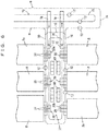
- FIG. 6 shows a second embodiment; the same symbols with FIGS. 1-5 represent the same elements, and it is similar to the first embodiment shown in FIGS. 1-5 but for the subsequently indicated points.
- another overhead transfer system 72 for transferring cassettes having special attributes in production control such as a hot-lot is provided.
- Respective travelling rails 74, 75 for the overhead transfer systems 8, 72 are arranged in parallel in an interbay route. If the overhead transfer vehicles 12 may directly enter into a bay 77 from the travelling rail 75 of the overhead transfer system 72, then, complex diverging and merging are necessary in the travelling rails.
- conveyors 78, 79 are provided so that they pass below travelling rails 74, 75, 10, the conveyor 78 is used to transport into the bay 77, and the conveyor 79 is used to transport to the overhead transfer system 72 out of the bay 77.
- a loop-like travelling rail 76 that passes over slide shelves 28 of for example plural purging apparatuses 20 is provided so that transfer vehicles such as the overhead transfer vehicles 12 may travel along it, and the slide shelves 28, the conveyors 78, 79, and the overhead transfer system 72 are mutually connected.
- buffers 80 are provided, and the overhead transfer vehicles 12 travelling along the travelling rail 76 transfer cassettes between the buffers 80 by the lateral movement device 13 in FIG. 1 .
- the buffers 80 may be provided with the purge function with the usage of N2 gas or not.
- the overhead transfer vehicles 12 travelling along the travelling rail 76 and the overhead transfer system 72 transfer cassettes such as those accommodating hot-lot wafers for emergent or priority transfer, empty cassettes, and cassettes accommodating process control wafers or wafers for inspection purpose. These cassettes are called cassettes having special attributes in production control.
- the conveyors 78, 79 connect the overhead transfer system 72 in the interbay route and overhead transfer vehicles travelling the travelling rail 76 in the bay 77. Further, a system comprising the travelling rail 76 and the overhead transfer vehicles 12 may be replaced by an arbitrary system for transferring cassettes in the ceiling space.
- a gantry crane which two-dimensionally travels in the bay 77, transfer vehicles which travel on a grid-like rail over the bay 77, or autonomously guided vehicles which do not block the clean air flow in the bay 77, etc. may be used. Note that these systems should be provided at an area higher than the purging apparatus 20.
- the embodiment in FIG. 6 makes various purging operations possible, for example, when transferring a cassette from first processing equipment 2a to second processing equipment 2b, the cassette is transferred to a purging apparatus 20b near to the second processing equipment 2b after purging at a purging apparatus 20a near to the first processing equipment 2a and further purged at the purging apparatus 20b, before being processed at the second processing equipment 2b.
- the buffers increase the storage capacity in the bay.
- the overhead transfer system 72, the conveyors 78, 79, and travelling rail 76, or the like compensate the transfer delay due to purging.
- Containers to be purged are not limited to the cassettes and are arbitrary, and articles to be accommodated may be medicines, foods, or the like, in addition to the semiconductor wafers.
Landscapes
- Engineering & Computer Science (AREA)
- Mechanical Engineering (AREA)
- Container, Conveyance, Adherence, Positioning, Of Wafer (AREA)
- Robotics (AREA)
- Warehouses Or Storage Devices (AREA)
- Carriers, Traveling Bodies, And Overhead Traveling Cranes (AREA)
Applications Claiming Priority (2)
| Application Number | Priority Date | Filing Date | Title |
|---|---|---|---|
| JP2014195152 | 2014-09-25 | ||
| PCT/JP2015/071011 WO2016047260A1 (ja) | 2014-09-25 | 2015-07-23 | パージ装置及びパージ方法 |
Publications (3)
| Publication Number | Publication Date |
|---|---|
| EP3200221A1 true EP3200221A1 (de) | 2017-08-02 |
| EP3200221A4 EP3200221A4 (de) | 2018-05-16 |
| EP3200221B1 EP3200221B1 (de) | 2021-05-05 |
Family
ID=55580794
Family Applications (1)
| Application Number | Title | Priority Date | Filing Date |
|---|---|---|---|
| EP15845065.0A Active EP3200221B1 (de) | 2014-09-25 | 2015-07-23 | Reinigungsvorrichtung und reinigungsverfahren |
Country Status (9)
| Country | Link |
|---|---|
| US (1) | US10325797B2 (de) |
| EP (1) | EP3200221B1 (de) |
| JP (1) | JP6241693B2 (de) |
| KR (2) | KR101942394B1 (de) |
| CN (1) | CN106796908B (de) |
| IL (1) | IL250119A (de) |
| SG (1) | SG11201700643UA (de) |
| TW (1) | TWI667437B (de) |
| WO (1) | WO2016047260A1 (de) |
Families Citing this family (15)
| Publication number | Priority date | Publication date | Assignee | Title |
|---|---|---|---|---|
| CN106796908B (zh) * | 2014-09-25 | 2019-11-26 | 村田机械株式会社 | 清洗装置以及清洗方法 |
| SG11201801076VA (en) * | 2015-08-14 | 2018-03-28 | Murata Machinery Ltd | Conveyance system |
| SG11201804593PA (en) * | 2015-12-08 | 2018-06-28 | Murata Machinery Ltd | Conveyance system and conveyance method |
| KR101852323B1 (ko) | 2016-07-05 | 2018-04-26 | 로체 시스템즈(주) | 퍼지 모듈 지그 및 이를 포함한 퍼지 모듈 |
| FR3080949B1 (fr) * | 2018-05-04 | 2021-05-28 | St Microelectronics Rousset | Dispositif de memoire non volatile du type a piegeage de charges et procede de fabrication |
| SG11202012260RA (en) | 2018-06-15 | 2021-01-28 | Murata Machinery Ltd | Storage shelf |
| JP7067621B2 (ja) * | 2018-07-20 | 2022-05-16 | 村田機械株式会社 | 保管棚及び保管棚の設置方法 |
| KR102530860B1 (ko) * | 2018-12-26 | 2023-05-10 | 무라다기카이가부시끼가이샤 | 보관 시스템 |
| JP7211439B2 (ja) * | 2019-01-25 | 2023-01-24 | 村田機械株式会社 | 搬送システム |
| JP7224725B2 (ja) * | 2019-03-26 | 2023-02-20 | 株式会社ディスコ | 搬送システム |
| KR102627684B1 (ko) * | 2019-11-05 | 2024-01-23 | 무라다기카이가부시끼가이샤 | 반송차 시스템 |
| CN116529180A (zh) * | 2020-11-12 | 2023-08-01 | 村田机械株式会社 | 保管架 |
| JP7327425B2 (ja) * | 2021-02-19 | 2023-08-16 | 株式会社ダイフク | 搬送設備 |
| KR102593950B1 (ko) * | 2021-12-29 | 2023-10-24 | 세메스 주식회사 | 유량공급장치 및 공급방법 |
| JP2025009152A (ja) * | 2023-07-07 | 2025-01-20 | 株式会社ディスコ | 搬送車 |
Family Cites Families (12)
| Publication number | Priority date | Publication date | Assignee | Title |
|---|---|---|---|---|
| US20080240892A1 (en) * | 2007-03-28 | 2008-10-02 | International Business Machines Corporation | Storage buffer device for automated material handling systems |
| KR101077566B1 (ko) | 2008-08-20 | 2011-10-28 | 세메스 주식회사 | 기판 처리장치 및 이의 기판 이송 방법 |
| JP4807424B2 (ja) * | 2009-03-17 | 2011-11-02 | 村田機械株式会社 | 天井搬送システムと物品の移載方法 |
| WO2010135205A2 (en) * | 2009-05-18 | 2010-11-25 | Crossing Automation, Inc. | Integrated systems for interfacing with substrate container storage systems |
| US8882433B2 (en) * | 2009-05-18 | 2014-11-11 | Brooks Automation, Inc. | Integrated systems for interfacing with substrate container storage systems |
| JP5429570B2 (ja) * | 2010-03-08 | 2014-02-26 | 株式会社ダイフク | 物品搬送設備 |
| JP5382470B2 (ja) * | 2010-11-04 | 2014-01-08 | 村田機械株式会社 | 搬送システム及び搬送方法 |
| JP5229363B2 (ja) | 2010-11-04 | 2013-07-03 | 村田機械株式会社 | 搬送システム及び搬送方法 |
| KR101495629B1 (ko) * | 2011-05-25 | 2015-02-25 | 무라다기카이가부시끼가이샤 | 로드 포트 장치, 반송 시스템 및 컨테이너 반출 방법 |
| KR101418812B1 (ko) * | 2012-10-31 | 2014-07-16 | 크린팩토메이션 주식회사 | 웨이퍼 퍼지 가능한 천장 보관 장치 |
| WO2014104895A1 (en) * | 2012-12-31 | 2014-07-03 | Asm Ip Holding B.V. | Semiconductor processing assembly and facility |
| CN106796908B (zh) * | 2014-09-25 | 2019-11-26 | 村田机械株式会社 | 清洗装置以及清洗方法 |
-
2015
- 2015-07-23 CN CN201580047207.7A patent/CN106796908B/zh active Active
- 2015-07-23 JP JP2016550006A patent/JP6241693B2/ja active Active
- 2015-07-23 EP EP15845065.0A patent/EP3200221B1/de active Active
- 2015-07-23 US US15/508,503 patent/US10325797B2/en active Active
- 2015-07-23 SG SG11201700643UA patent/SG11201700643UA/en unknown
- 2015-07-23 IL IL250119A patent/IL250119A/en active IP Right Grant
- 2015-07-23 KR KR1020187035642A patent/KR101942394B1/ko active Active
- 2015-07-23 WO PCT/JP2015/071011 patent/WO2016047260A1/ja not_active Ceased
- 2015-07-23 KR KR1020177010018A patent/KR20170058393A/ko not_active Ceased
- 2015-09-23 TW TW104131471A patent/TWI667437B/zh active
Also Published As
| Publication number | Publication date |
|---|---|
| KR101942394B1 (ko) | 2019-01-25 |
| CN106796908B (zh) | 2019-11-26 |
| WO2016047260A1 (ja) | 2016-03-31 |
| TWI667437B (zh) | 2019-08-01 |
| TW201612472A (en) | 2016-04-01 |
| IL250119A (en) | 2017-05-29 |
| SG11201700643UA (en) | 2017-04-27 |
| JP6241693B2 (ja) | 2017-12-06 |
| JPWO2016047260A1 (ja) | 2017-06-15 |
| EP3200221A4 (de) | 2018-05-16 |
| KR20170058393A (ko) | 2017-05-26 |
| US20170278736A1 (en) | 2017-09-28 |
| KR20180135090A (ko) | 2018-12-19 |
| CN106796908A (zh) | 2017-05-31 |
| IL250119A0 (en) | 2017-03-30 |
| EP3200221B1 (de) | 2021-05-05 |
| US10325797B2 (en) | 2019-06-18 |
Similar Documents
| Publication | Publication Date | Title |
|---|---|---|
| EP3200221B1 (de) | Reinigungsvorrichtung und reinigungsverfahren | |
| US9548230B2 (en) | Temporary storage device, transport system, and temporary storage method | |
| US9701431B2 (en) | Load port device, transport system, and container carrying out method | |
| CN109415163B (zh) | 输送系统 | |
| KR101463473B1 (ko) | 이송 장치 | |
| TWI644266B (zh) | 頂棚保管系統及在頂棚空間的貨物之保管方法 | |
| US10153189B2 (en) | Carrier buffering device and buffering method | |
| CN107534004B (zh) | 清洗堆料机以及清洗方法 | |
| TW201351551A (zh) | 用於半導體製程區之晶圓處理系統以及在半導體設備間輸送晶圓之裝置及方法 | |
| EP3680930B1 (de) | Speichersystem und reinigungsverfahren in einem speichersystem | |
| US20090022575A1 (en) | Article storing apparatus | |
| KR20170051641A (ko) | 기판 이송 용기 저장 장치 | |
| KR20170057848A (ko) | 용기 반송 설비 | |
| US20200264506A1 (en) | Article Storage Facility | |
| US11508596B2 (en) | Apparatus and methods for automatically handling die carriers | |
| TW202233505A (zh) | 搬送設備 | |
| KR20240096121A (ko) | 물류 반송 설비 및 물류 반송 방법 | |
| CN121359627A (zh) | 保管系统 |
Legal Events
| Date | Code | Title | Description |
|---|---|---|---|
| STAA | Information on the status of an ep patent application or granted ep patent |
Free format text: STATUS: THE INTERNATIONAL PUBLICATION HAS BEEN MADE |
|
| PUAI | Public reference made under article 153(3) epc to a published international application that has entered the european phase |
Free format text: ORIGINAL CODE: 0009012 |
|
| STAA | Information on the status of an ep patent application or granted ep patent |
Free format text: STATUS: REQUEST FOR EXAMINATION WAS MADE |
|
| 17P | Request for examination filed |
Effective date: 20170321 |
|
| AK | Designated contracting states |
Kind code of ref document: A1 Designated state(s): AL AT BE BG CH CY CZ DE DK EE ES FI FR GB GR HR HU IE IS IT LI LT LU LV MC MK MT NL NO PL PT RO RS SE SI SK SM TR |
|
| AX | Request for extension of the european patent |
Extension state: BA ME |
|
| DAV | Request for validation of the european patent (deleted) | ||
| DAX | Request for extension of the european patent (deleted) | ||
| A4 | Supplementary search report drawn up and despatched |
Effective date: 20180417 |
|
| RIC1 | Information provided on ipc code assigned before grant |
Ipc: H01L 21/673 20060101ALI20180411BHEP Ipc: H01L 21/54 20060101ALI20180411BHEP Ipc: G05D 7/06 20060101ALI20180411BHEP Ipc: H01L 21/677 20060101AFI20180411BHEP |
|
| GRAP | Despatch of communication of intention to grant a patent |
Free format text: ORIGINAL CODE: EPIDOSNIGR1 |
|
| STAA | Information on the status of an ep patent application or granted ep patent |
Free format text: STATUS: GRANT OF PATENT IS INTENDED |
|
| INTG | Intention to grant announced |
Effective date: 20201125 |
|
| RIN1 | Information on inventor provided before grant (corrected) |
Inventor name: IWASAKI, JUNJI |
|
| GRAS | Grant fee paid |
Free format text: ORIGINAL CODE: EPIDOSNIGR3 |
|
| GRAA | (expected) grant |
Free format text: ORIGINAL CODE: 0009210 |
|
| STAA | Information on the status of an ep patent application or granted ep patent |
Free format text: STATUS: THE PATENT HAS BEEN GRANTED |
|
| AK | Designated contracting states |
Kind code of ref document: B1 Designated state(s): AL AT BE BG CH CY CZ DE DK EE ES FI FR GB GR HR HU IE IS IT LI LT LU LV MC MK MT NL NO PL PT RO RS SE SI SK SM TR |
|
| REG | Reference to a national code |
Ref country code: GB Ref legal event code: FG4D |
|
| REG | Reference to a national code |
Ref country code: CH Ref legal event code: EP |
|
| REG | Reference to a national code |
Ref country code: AT Ref legal event code: REF Ref document number: 1390873 Country of ref document: AT Kind code of ref document: T Effective date: 20210515 |
|
| REG | Reference to a national code |
Ref country code: DE Ref legal event code: R096 Ref document number: 602015069098 Country of ref document: DE |
|
| REG | Reference to a national code |
Ref country code: IE Ref legal event code: FG4D |
|
| REG | Reference to a national code |
Ref country code: LT Ref legal event code: MG9D |
|
| REG | Reference to a national code |
Ref country code: AT Ref legal event code: MK05 Ref document number: 1390873 Country of ref document: AT Kind code of ref document: T Effective date: 20210505 |
|
| PG25 | Lapsed in a contracting state [announced via postgrant information from national office to epo] |
Ref country code: LT Free format text: LAPSE BECAUSE OF FAILURE TO SUBMIT A TRANSLATION OF THE DESCRIPTION OR TO PAY THE FEE WITHIN THE PRESCRIBED TIME-LIMIT Effective date: 20210505 Ref country code: FI Free format text: LAPSE BECAUSE OF FAILURE TO SUBMIT A TRANSLATION OF THE DESCRIPTION OR TO PAY THE FEE WITHIN THE PRESCRIBED TIME-LIMIT Effective date: 20210505 Ref country code: HR Free format text: LAPSE BECAUSE OF FAILURE TO SUBMIT A TRANSLATION OF THE DESCRIPTION OR TO PAY THE FEE WITHIN THE PRESCRIBED TIME-LIMIT Effective date: 20210505 Ref country code: AT Free format text: LAPSE BECAUSE OF FAILURE TO SUBMIT A TRANSLATION OF THE DESCRIPTION OR TO PAY THE FEE WITHIN THE PRESCRIBED TIME-LIMIT Effective date: 20210505 Ref country code: BG Free format text: LAPSE BECAUSE OF FAILURE TO SUBMIT A TRANSLATION OF THE DESCRIPTION OR TO PAY THE FEE WITHIN THE PRESCRIBED TIME-LIMIT Effective date: 20210805 |
|
| PG25 | Lapsed in a contracting state [announced via postgrant information from national office to epo] |
Ref country code: LV Free format text: LAPSE BECAUSE OF FAILURE TO SUBMIT A TRANSLATION OF THE DESCRIPTION OR TO PAY THE FEE WITHIN THE PRESCRIBED TIME-LIMIT Effective date: 20210505 Ref country code: IS Free format text: LAPSE BECAUSE OF FAILURE TO SUBMIT A TRANSLATION OF THE DESCRIPTION OR TO PAY THE FEE WITHIN THE PRESCRIBED TIME-LIMIT Effective date: 20210905 Ref country code: GR Free format text: LAPSE BECAUSE OF FAILURE TO SUBMIT A TRANSLATION OF THE DESCRIPTION OR TO PAY THE FEE WITHIN THE PRESCRIBED TIME-LIMIT Effective date: 20210806 Ref country code: PL Free format text: LAPSE BECAUSE OF FAILURE TO SUBMIT A TRANSLATION OF THE DESCRIPTION OR TO PAY THE FEE WITHIN THE PRESCRIBED TIME-LIMIT Effective date: 20210505 Ref country code: PT Free format text: LAPSE BECAUSE OF FAILURE TO SUBMIT A TRANSLATION OF THE DESCRIPTION OR TO PAY THE FEE WITHIN THE PRESCRIBED TIME-LIMIT Effective date: 20210906 Ref country code: NO Free format text: LAPSE BECAUSE OF FAILURE TO SUBMIT A TRANSLATION OF THE DESCRIPTION OR TO PAY THE FEE WITHIN THE PRESCRIBED TIME-LIMIT Effective date: 20210805 Ref country code: SE Free format text: LAPSE BECAUSE OF FAILURE TO SUBMIT A TRANSLATION OF THE DESCRIPTION OR TO PAY THE FEE WITHIN THE PRESCRIBED TIME-LIMIT Effective date: 20210505 Ref country code: RS Free format text: LAPSE BECAUSE OF FAILURE TO SUBMIT A TRANSLATION OF THE DESCRIPTION OR TO PAY THE FEE WITHIN THE PRESCRIBED TIME-LIMIT Effective date: 20210505 |
|
| REG | Reference to a national code |
Ref country code: NL Ref legal event code: MP Effective date: 20210505 |
|
| PG25 | Lapsed in a contracting state [announced via postgrant information from national office to epo] |
Ref country code: NL Free format text: LAPSE BECAUSE OF FAILURE TO SUBMIT A TRANSLATION OF THE DESCRIPTION OR TO PAY THE FEE WITHIN THE PRESCRIBED TIME-LIMIT Effective date: 20210505 |
|
| PG25 | Lapsed in a contracting state [announced via postgrant information from national office to epo] |
Ref country code: DK Free format text: LAPSE BECAUSE OF FAILURE TO SUBMIT A TRANSLATION OF THE DESCRIPTION OR TO PAY THE FEE WITHIN THE PRESCRIBED TIME-LIMIT Effective date: 20210505 Ref country code: CZ Free format text: LAPSE BECAUSE OF FAILURE TO SUBMIT A TRANSLATION OF THE DESCRIPTION OR TO PAY THE FEE WITHIN THE PRESCRIBED TIME-LIMIT Effective date: 20210505 Ref country code: EE Free format text: LAPSE BECAUSE OF FAILURE TO SUBMIT A TRANSLATION OF THE DESCRIPTION OR TO PAY THE FEE WITHIN THE PRESCRIBED TIME-LIMIT Effective date: 20210505 Ref country code: SK Free format text: LAPSE BECAUSE OF FAILURE TO SUBMIT A TRANSLATION OF THE DESCRIPTION OR TO PAY THE FEE WITHIN THE PRESCRIBED TIME-LIMIT Effective date: 20210505 Ref country code: SM Free format text: LAPSE BECAUSE OF FAILURE TO SUBMIT A TRANSLATION OF THE DESCRIPTION OR TO PAY THE FEE WITHIN THE PRESCRIBED TIME-LIMIT Effective date: 20210505 Ref country code: RO Free format text: LAPSE BECAUSE OF FAILURE TO SUBMIT A TRANSLATION OF THE DESCRIPTION OR TO PAY THE FEE WITHIN THE PRESCRIBED TIME-LIMIT Effective date: 20210505 Ref country code: ES Free format text: LAPSE BECAUSE OF FAILURE TO SUBMIT A TRANSLATION OF THE DESCRIPTION OR TO PAY THE FEE WITHIN THE PRESCRIBED TIME-LIMIT Effective date: 20210505 |
|
| REG | Reference to a national code |
Ref country code: DE Ref legal event code: R097 Ref document number: 602015069098 Country of ref document: DE |
|
| REG | Reference to a national code |
Ref country code: CH Ref legal event code: PL |
|
| PLBE | No opposition filed within time limit |
Free format text: ORIGINAL CODE: 0009261 |
|
| STAA | Information on the status of an ep patent application or granted ep patent |
Free format text: STATUS: NO OPPOSITION FILED WITHIN TIME LIMIT |
|
| PG25 | Lapsed in a contracting state [announced via postgrant information from national office to epo] |
Ref country code: MC Free format text: LAPSE BECAUSE OF FAILURE TO SUBMIT A TRANSLATION OF THE DESCRIPTION OR TO PAY THE FEE WITHIN THE PRESCRIBED TIME-LIMIT Effective date: 20210505 |
|
| REG | Reference to a national code |
Ref country code: BE Ref legal event code: MM Effective date: 20210731 |
|
| 26N | No opposition filed |
Effective date: 20220208 |
|
| GBPC | Gb: european patent ceased through non-payment of renewal fee |
Effective date: 20210805 |
|
| PG25 | Lapsed in a contracting state [announced via postgrant information from national office to epo] |
Ref country code: LI Free format text: LAPSE BECAUSE OF NON-PAYMENT OF DUE FEES Effective date: 20210731 Ref country code: CH Free format text: LAPSE BECAUSE OF NON-PAYMENT OF DUE FEES Effective date: 20210731 |
|
| PG25 | Lapsed in a contracting state [announced via postgrant information from national office to epo] |
Ref country code: IS Free format text: LAPSE BECAUSE OF FAILURE TO SUBMIT A TRANSLATION OF THE DESCRIPTION OR TO PAY THE FEE WITHIN THE PRESCRIBED TIME-LIMIT Effective date: 20210905 Ref country code: LU Free format text: LAPSE BECAUSE OF NON-PAYMENT OF DUE FEES Effective date: 20210723 Ref country code: FR Free format text: LAPSE BECAUSE OF NON-PAYMENT OF DUE FEES Effective date: 20210731 Ref country code: AL Free format text: LAPSE BECAUSE OF FAILURE TO SUBMIT A TRANSLATION OF THE DESCRIPTION OR TO PAY THE FEE WITHIN THE PRESCRIBED TIME-LIMIT Effective date: 20210505 |
|
| PG25 | Lapsed in a contracting state [announced via postgrant information from national office to epo] |
Ref country code: IT Free format text: LAPSE BECAUSE OF FAILURE TO SUBMIT A TRANSLATION OF THE DESCRIPTION OR TO PAY THE FEE WITHIN THE PRESCRIBED TIME-LIMIT Effective date: 20210505 Ref country code: GB Free format text: LAPSE BECAUSE OF NON-PAYMENT OF DUE FEES Effective date: 20210805 Ref country code: BE Free format text: LAPSE BECAUSE OF NON-PAYMENT OF DUE FEES Effective date: 20210731 |
|
| PG25 | Lapsed in a contracting state [announced via postgrant information from national office to epo] |
Ref country code: HU Free format text: LAPSE BECAUSE OF FAILURE TO SUBMIT A TRANSLATION OF THE DESCRIPTION OR TO PAY THE FEE WITHIN THE PRESCRIBED TIME-LIMIT; INVALID AB INITIO Effective date: 20150723 |
|
| PG25 | Lapsed in a contracting state [announced via postgrant information from national office to epo] |
Ref country code: CY Free format text: LAPSE BECAUSE OF FAILURE TO SUBMIT A TRANSLATION OF THE DESCRIPTION OR TO PAY THE FEE WITHIN THE PRESCRIBED TIME-LIMIT Effective date: 20210505 |
|
| PG25 | Lapsed in a contracting state [announced via postgrant information from national office to epo] |
Ref country code: MK Free format text: LAPSE BECAUSE OF FAILURE TO SUBMIT A TRANSLATION OF THE DESCRIPTION OR TO PAY THE FEE WITHIN THE PRESCRIBED TIME-LIMIT Effective date: 20210505 |
|
| PG25 | Lapsed in a contracting state [announced via postgrant information from national office to epo] |
Ref country code: MT Free format text: LAPSE BECAUSE OF FAILURE TO SUBMIT A TRANSLATION OF THE DESCRIPTION OR TO PAY THE FEE WITHIN THE PRESCRIBED TIME-LIMIT Effective date: 20210505 |
|
| PGFP | Annual fee paid to national office [announced via postgrant information from national office to epo] |
Ref country code: IE Payment date: 20250623 Year of fee payment: 11 |
|
| PGFP | Annual fee paid to national office [announced via postgrant information from national office to epo] |
Ref country code: DE Payment date: 20250620 Year of fee payment: 11 |
|
| REG | Reference to a national code |
Ref country code: DE Ref legal event code: R079 Ref document number: 602015069098 Country of ref document: DE Free format text: PREVIOUS MAIN CLASS: H01L0021677000 Ipc: H10P0072300000 |
|
| PG25 | Lapsed in a contracting state [announced via postgrant information from national office to epo] |
Ref country code: TR Free format text: LAPSE BECAUSE OF FAILURE TO SUBMIT A TRANSLATION OF THE DESCRIPTION OR TO PAY THE FEE WITHIN THE PRESCRIBED TIME-LIMIT Effective date: 20210505 |