EP3199413A1 - Dispositif d'actionneur - Google Patents
Dispositif d'actionneur Download PDFInfo
- Publication number
- EP3199413A1 EP3199413A1 EP16152954.0A EP16152954A EP3199413A1 EP 3199413 A1 EP3199413 A1 EP 3199413A1 EP 16152954 A EP16152954 A EP 16152954A EP 3199413 A1 EP3199413 A1 EP 3199413A1
- Authority
- EP
- European Patent Office
- Prior art keywords
- flywheel
- actuator device
- actuator
- transmission element
- blocking
- Prior art date
- Legal status (The legal status is an assumption and is not a legal conclusion. Google has not performed a legal analysis and makes no representation as to the accuracy of the status listed.)
- Withdrawn
Links
Images


Classifications
-
- G—PHYSICS
- G05—CONTROLLING; REGULATING
- G05G—CONTROL DEVICES OR SYSTEMS INSOFAR AS CHARACTERISED BY MECHANICAL FEATURES ONLY
- G05G1/00—Controlling members, e.g. knobs or handles; Assemblies or arrangements thereof; Indicating position of controlling members
- G05G1/54—Controlling members specially adapted for actuation by auxiliary operating members or extensions; Operating members or extensions therefor (pedal extensions)
-
- B—PERFORMING OPERATIONS; TRANSPORTING
- B60—VEHICLES IN GENERAL
- B60T—VEHICLE BRAKE CONTROL SYSTEMS OR PARTS THEREOF; BRAKE CONTROL SYSTEMS OR PARTS THEREOF, IN GENERAL; ARRANGEMENT OF BRAKING ELEMENTS ON VEHICLES IN GENERAL; PORTABLE DEVICES FOR PREVENTING UNWANTED MOVEMENT OF VEHICLES; VEHICLE MODIFICATIONS TO FACILITATE COOLING OF BRAKES
- B60T7/00—Brake-action initiating means
- B60T7/02—Brake-action initiating means for personal initiation
- B60T7/04—Brake-action initiating means for personal initiation foot actuated
- B60T7/045—Brake-action initiating means for personal initiation foot actuated with locking and release means, e.g. providing parking brake application
-
- B—PERFORMING OPERATIONS; TRANSPORTING
- B60—VEHICLES IN GENERAL
- B60T—VEHICLE BRAKE CONTROL SYSTEMS OR PARTS THEREOF; BRAKE CONTROL SYSTEMS OR PARTS THEREOF, IN GENERAL; ARRANGEMENT OF BRAKING ELEMENTS ON VEHICLES IN GENERAL; PORTABLE DEVICES FOR PREVENTING UNWANTED MOVEMENT OF VEHICLES; VEHICLE MODIFICATIONS TO FACILITATE COOLING OF BRAKES
- B60T7/00—Brake-action initiating means
- B60T7/12—Brake-action initiating means for automatic initiation; for initiation not subject to will of driver or passenger
-
- F—MECHANICAL ENGINEERING; LIGHTING; HEATING; WEAPONS; BLASTING
- F16—ENGINEERING ELEMENTS AND UNITS; GENERAL MEASURES FOR PRODUCING AND MAINTAINING EFFECTIVE FUNCTIONING OF MACHINES OR INSTALLATIONS; THERMAL INSULATION IN GENERAL
- F16D—COUPLINGS FOR TRANSMITTING ROTATION; CLUTCHES; BRAKES
- F16D41/00—Freewheels or freewheel clutches
- F16D41/06—Freewheels or freewheel clutches with intermediate wedging coupling members between an inner and an outer surface
- F16D41/064—Freewheels or freewheel clutches with intermediate wedging coupling members between an inner and an outer surface the intermediate members wedging by rolling and having a circular cross-section, e.g. balls
- F16D41/066—Freewheels or freewheel clutches with intermediate wedging coupling members between an inner and an outer surface the intermediate members wedging by rolling and having a circular cross-section, e.g. balls all members having the same size and only one of the two surfaces being cylindrical
-
- F—MECHANICAL ENGINEERING; LIGHTING; HEATING; WEAPONS; BLASTING
- F16—ENGINEERING ELEMENTS AND UNITS; GENERAL MEASURES FOR PRODUCING AND MAINTAINING EFFECTIVE FUNCTIONING OF MACHINES OR INSTALLATIONS; THERMAL INSULATION IN GENERAL
- F16F—SPRINGS; SHOCK-ABSORBERS; MEANS FOR DAMPING VIBRATION
- F16F15/00—Suppression of vibrations in systems; Means or arrangements for avoiding or reducing out-of-balance forces, e.g. due to motion
- F16F15/30—Flywheels
-
- F—MECHANICAL ENGINEERING; LIGHTING; HEATING; WEAPONS; BLASTING
- F16—ENGINEERING ELEMENTS AND UNITS; GENERAL MEASURES FOR PRODUCING AND MAINTAINING EFFECTIVE FUNCTIONING OF MACHINES OR INSTALLATIONS; THERMAL INSULATION IN GENERAL
- F16H—GEARING
- F16H1/00—Toothed gearings for conveying rotary motion
- F16H1/28—Toothed gearings for conveying rotary motion with gears having orbital motion
-
- B—PERFORMING OPERATIONS; TRANSPORTING
- B60—VEHICLES IN GENERAL
- B60K—ARRANGEMENT OR MOUNTING OF PROPULSION UNITS OR OF TRANSMISSIONS IN VEHICLES; ARRANGEMENT OR MOUNTING OF PLURAL DIVERSE PRIME-MOVERS IN VEHICLES; AUXILIARY DRIVES FOR VEHICLES; INSTRUMENTATION OR DASHBOARDS FOR VEHICLES; ARRANGEMENTS IN CONNECTION WITH COOLING, AIR INTAKE, GAS EXHAUST OR FUEL SUPPLY OF PROPULSION UNITS IN VEHICLES
- B60K26/00—Arrangements or mounting of propulsion unit control devices in vehicles
- B60K26/04—Arrangements or mounting of propulsion unit control devices in vehicles of means connecting initiating means or elements to propulsion unit
- B60K2026/043—Arrangements or mounting of propulsion unit control devices in vehicles of means connecting initiating means or elements to propulsion unit with mechanical gearings
-
- B—PERFORMING OPERATIONS; TRANSPORTING
- B60—VEHICLES IN GENERAL
- B60K—ARRANGEMENT OR MOUNTING OF PROPULSION UNITS OR OF TRANSMISSIONS IN VEHICLES; ARRANGEMENT OR MOUNTING OF PLURAL DIVERSE PRIME-MOVERS IN VEHICLES; AUXILIARY DRIVES FOR VEHICLES; INSTRUMENTATION OR DASHBOARDS FOR VEHICLES; ARRANGEMENTS IN CONNECTION WITH COOLING, AIR INTAKE, GAS EXHAUST OR FUEL SUPPLY OF PROPULSION UNITS IN VEHICLES
- B60K23/00—Arrangement or mounting of control devices for vehicle transmissions, or parts thereof, not otherwise provided for
- B60K23/02—Arrangement or mounting of control devices for vehicle transmissions, or parts thereof, not otherwise provided for for main transmission clutches
-
- B—PERFORMING OPERATIONS; TRANSPORTING
- B60—VEHICLES IN GENERAL
- B60K—ARRANGEMENT OR MOUNTING OF PROPULSION UNITS OR OF TRANSMISSIONS IN VEHICLES; ARRANGEMENT OR MOUNTING OF PLURAL DIVERSE PRIME-MOVERS IN VEHICLES; AUXILIARY DRIVES FOR VEHICLES; INSTRUMENTATION OR DASHBOARDS FOR VEHICLES; ARRANGEMENTS IN CONNECTION WITH COOLING, AIR INTAKE, GAS EXHAUST OR FUEL SUPPLY OF PROPULSION UNITS IN VEHICLES
- B60K26/00—Arrangements or mounting of propulsion unit control devices in vehicles
- B60K26/04—Arrangements or mounting of propulsion unit control devices in vehicles of means connecting initiating means or elements to propulsion unit
-
- B—PERFORMING OPERATIONS; TRANSPORTING
- B60—VEHICLES IN GENERAL
- B60T—VEHICLE BRAKE CONTROL SYSTEMS OR PARTS THEREOF; BRAKE CONTROL SYSTEMS OR PARTS THEREOF, IN GENERAL; ARRANGEMENT OF BRAKING ELEMENTS ON VEHICLES IN GENERAL; PORTABLE DEVICES FOR PREVENTING UNWANTED MOVEMENT OF VEHICLES; VEHICLE MODIFICATIONS TO FACILITATE COOLING OF BRAKES
- B60T7/00—Brake-action initiating means
- B60T7/02—Brake-action initiating means for personal initiation
- B60T7/04—Brake-action initiating means for personal initiation foot actuated
-
- G—PHYSICS
- G01—MEASURING; TESTING
- G01L—MEASURING FORCE, STRESS, TORQUE, WORK, MECHANICAL POWER, MECHANICAL EFFICIENCY, OR FLUID PRESSURE
- G01L5/00—Apparatus for, or methods of, measuring force, work, mechanical power, or torque, specially adapted for specific purposes
- G01L5/22—Apparatus for, or methods of, measuring force, work, mechanical power, or torque, specially adapted for specific purposes for measuring the force applied to control members, e.g. control members of vehicles, triggers
- G01L5/225—Apparatus for, or methods of, measuring force, work, mechanical power, or torque, specially adapted for specific purposes for measuring the force applied to control members, e.g. control members of vehicles, triggers to foot actuated controls, e.g. brake pedals
Definitions
- the invention relates to an actuator device for actuating at least one foot pedal of a motor vehicle, such as a brake, gas or clutch pedal, according to the preamble of claim 1.
- the actuator device comprises at least one actuating element, which by means of an actuating mechanism between a Beaufschlagungswolf in which the relevant Foot pedal is pressed, and a release position is displaced, in which the relevant foot pedal is released and thus assumes a starting position.
- an actuator device which has an actuating element for acting on a foot pedal. Furthermore, an emergency device is provided by means of the foot pedal can be spent in an emergency exhibition. For this purpose, the Notausvorides on a gas spring, by means of which the actuating element in the direction of emergency exhibition can be acted upon with a force.
- the actuator can be spent, for example, in the emergency exhibition, when a supply energy of the actuator device drops or completely fails.
- the emergency exhibition can be formed by the release position, as in the case of a brake or clutch pedal by the respective admission position, or as in the case of an accelerator pedal.
- the gas spring In order to be able to ensure a safe displacement of the foot pedal in the respective emergency exhibition, the gas spring must be dimensioned sufficiently large in any case, whereby a total of a relatively large space must be provided for the Notausvorraum and the actuator.
- the object of the invention is to enable a more compact actuator design in a generic actuator device.
- an actuator device having the features of claim 1.
- the adjusting mechanism can be acted upon by a flywheel with a force in order to drive this and to shift the actuator.
- the actuating element by means of the flywheel, which acts either alone as a regular drive or in addition to a conventional drive as Notstellantrieb be moved between the Beaufschlagungswolf and the release position. In this way, a relatively compact construction of the actuator device overall is possible even when providing an emergency stop function.
- the flywheel is formed by a flywheel, which can be driven around an axis.
- the flywheel forms or has a rotor which can be driven by an internal stator.
- a simple permanent drive of the flywheel during operation of the actuator device is possible, for which only a minimum amount of electrical energy must be provided.
- the flywheel can be coupled via a gear transmission with a transmission element, via which the kinetic energy of the flywheel can be impulsively transmitted to the actuating mechanism.
- a very direct force or torque transmission from the flywheel to the transmission element and from this via the adjusting mechanism on the actuating element allows.
- the gear transmission is formed by a planetary gear with multiple planetary gears, which mesh with the inside of the flywheel and the outside with the transmission element.
- the planet gears are held on a rotatable planet carrier, which can be blocked by a blocking device along a direction of rotation.
- a blocking device along a direction of rotation.
- a freewheel device by means of which the transmission element can be blocked against a direction of impingement along which the pulse-like power transmission takes place from the flywheel.
- the transmission element, as well as on this and the actuating mechanism and the actuator can be kept after the pulse-like application of force by the flywheel by means of the Freüauf coupled in the respective pulse-like position, as in particular in the case of a brake or clutch pedal in the Beaufschlagungswolf or Trap of an accelerator pedal in the release position.
- the blocking device can in this case be actuated together with the freewheel device in order to be able to ensure a fixation of the actuating element immediately after it has been acted upon.
- the freewheel device on a ball which can be unrolled in a blocking position of the blocking device in a first direction along a circumferential guide groove of the transmission element. In a direction opposite to the first direction second direction, however, the ball is braked or clamped to the blocking device.
- the flywheel is formed as part of a redundant Notstellantriebes, by means of which the adjusting mechanism can be driven in addition to a standard drive.
- the actuator device can be activated in normal operation, for example via a servomotor, to reposition the actuator back and forth between the loading position and the release position.
- the flywheel is permanently driven.
- the kinetic energy of the flywheel can then be used to spend the adjusting mechanism or the actuator in a predetermined position, which corresponds in particular to an emergency exhibition.
- the flywheel itself may be formed as part of a regular drive through which the normal operation of the actuator device takes place.
- a usual standard drive for example in the form of a servomotor, can be dispensed with.
- a particularly compact design of the actuator device is possible.
- the operating costs of the actuator device can be significantly reduced because the time required to maintain the required rotational speed of the flywheel energy is only a fraction of the energy required in the case of a direct drive with a conventional servomotor.
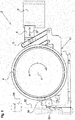
- Fig. 1 shows an actuator 2 with an actuating element 8, which can be acted upon via an adjusting mechanism 10 with a force SF.
- the actuating element 8 can be displaced between a loading position and a release position, in which a foot pedal P of a motor vehicle is acted upon or released.
- the adjusting mechanism 10 has a substantially Radförmiges transmission element 4 rotatable about an axis A, which is coupled in a manner not shown via a linkage 6 with the actuating element 8.
- the adjusting mechanism 10 in the normal operation of the actuator device are actuated by a motor 12.
- This is rotatably connected via a shaft 14 with an axle 16 of the transmission element 4.
- an annular flywheel 18 is provided, which forms a flywheel, which is also rotatable about the axis A around.
- the flywheel 18 is exemplarily formed integrally with a rotor 20 which can be driven by an internal stator 22.
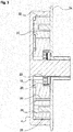
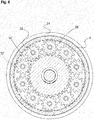
- the flywheel 18 forms together with a plurality of planetary gears 26 held on a planetary carrier 24 and with the transmission element 4 a planetary gear 28, as can be seen in particular from FIGS Figures 3 and 4 can be seen.
- the flywheel 18 has for this purpose on its outer side an outer toothing 30, which meshes with the planet gears 26.
- the transmission element 4 on its inner side an internal toothing 32, which also meshes with the planet gears 26.
- the planet gears 26 themselves are in turn held freely rotatable on the planet carrier 24.
- the actuator 2 has a blocking device 34, by means of which a rotational movement of the planet carrier 24 can be blocked about the axis A.
- the blocking device 34 is held pivotably relative to the planet carrier 24 and has a clamping receptacle 36, which in one in the FIGS. 5 and 6 shown blocking position can be clamped to an outer edge of the planet carrier 24.
- a freewheel device 37 is provided on the blocking device 34, by means of which the transmission element 4 along a direction of rotation D, which is directed against a loading direction BR, can be blocked.
- the freewheel device 36 has a on a housing 38 of the blocking device 34 rotatably held ball 40 which abuts in the blocking position of the blocking device 34 on a recessed into an outer surface 44 of the transmission element 4 guide groove 42. In this position, the ball 40 can roll in the blocking position along the guide groove 42, as long as the transmission element 4 is rotated along the direction of application BR.
- the direction of rotation D of the transmission element 4 conversely reverses, a rotation of the ball 40 is blocked by the housing 38 and thus also a rotation of the transmission element 4 against the biasing direction BR.
- the motor 12 serves as a standard drive 46 of the actuating mechanism 10, by means of which the foot pedal P can be repeatedly shifted by acting on the actuating element 8 with the actuating force SF between the Beauftschungswolf and the release position.
- the motor 12 is rotated in the respective desired direction, wherein the torque generated in this case is transmitted to the transmission element 4 via the shaft 14 and the axle element 16. From this then takes place the power transmission via the linkage 6 to the actuating element 8, which is thereby displaced from the deflection position to the release position or vice versa.
- a remote controlled or automated operation of the actuator 2 such as during a driving test or on a test stand possible.
- the flywheel 18 driven by the rotor 20 acts together with the remaining planetary gear 28 as an additional redundant emergency actuator 48.
- the rotor 20 of the flywheel 18 is permanently driven independently of the motor 12 via the stator 22 or kept in motion.
- the meshing with the external teeth 30 planet gears 26 roll while rotating the planet carrier 24 about the axis A around on the internal teeth 32 of the transmission element 4 from.
- the energy of the rotating flywheel 18 can be used to act on the actuating mechanism 10.
- the blocking device 34 from the in FIG. 1 illustrated release position by means of an activation device 50, which is connected for example via a line 52 or via radio with a triggering device 54 and can be triggered via this, displaced or pivoted in the blocking position shown with dash-dotted lines, the emergency exhibition equivalent.
- the triggering device 54 may be formed, for example, as shown by an emergency release.
- the Freüauf worn 37 also allows in the blocking position of the blocking device 34 is a continuous rotational movement of the transmission element 4 in Beauftschungscardi BR. However, as soon as an opposing rotational movement on the transmission element 4 is generated by restoring forces of the foot pedal P or the adjusting mechanism 10, the ball 40 of the freewheel device 37 is clamped to the housing 38 and the transmission element 4 held together with the adjusting mechanism 10 and the actuator 8 in position to maintain the emergency exhibition.
- the flywheel 18 in conjunction with the remaining planetary gear 28 as a regular drive for normal operation of the actuator device 2 to use.
- Such a use is suitable, for example, for test benches in which the service life of foot pedals P is checked by their repeated application of a predefined test load. These are for the Build up the required rotational energy several seconds available, while the force call must be made only for fractions of a second.
- the power requirement of serving as a standard drive in this case flywheel 18 in conjunction with the planetary gear 28 is only a fraction of the energy requirements of a conventional drive, such as a conventional servomotor. In this way, the operating costs of the actuator 2 can be significantly reduced.
- the actuator 2 can be made very compact in this way, since on the standard drive 46 formed by the motor 12 in accordance with Fig. 2 can be completely dispensed with.
Landscapes
- Engineering & Computer Science (AREA)
- General Engineering & Computer Science (AREA)
- Mechanical Engineering (AREA)
- Transportation (AREA)
- Physics & Mathematics (AREA)
- Acoustics & Sound (AREA)
- Aviation & Aerospace Engineering (AREA)
- General Physics & Mathematics (AREA)
- Automation & Control Theory (AREA)
- Connection Of Motors, Electrical Generators, Mechanical Devices, And The Like (AREA)
Priority Applications (2)
| Application Number | Priority Date | Filing Date | Title |
|---|---|---|---|
| EP16152954.0A EP3199413A1 (fr) | 2016-01-27 | 2016-01-27 | Dispositif d'actionneur |
| US15/416,999 US10401894B2 (en) | 2016-01-27 | 2017-01-26 | Actuator device |
Applications Claiming Priority (1)
| Application Number | Priority Date | Filing Date | Title |
|---|---|---|---|
| EP16152954.0A EP3199413A1 (fr) | 2016-01-27 | 2016-01-27 | Dispositif d'actionneur |
Publications (1)
| Publication Number | Publication Date |
|---|---|
| EP3199413A1 true EP3199413A1 (fr) | 2017-08-02 |
Family
ID=55237576
Family Applications (1)
| Application Number | Title | Priority Date | Filing Date |
|---|---|---|---|
| EP16152954.0A Withdrawn EP3199413A1 (fr) | 2016-01-27 | 2016-01-27 | Dispositif d'actionneur |
Country Status (2)
| Country | Link |
|---|---|
| US (1) | US10401894B2 (fr) |
| EP (1) | EP3199413A1 (fr) |
Cited By (1)
| Publication number | Priority date | Publication date | Assignee | Title |
|---|---|---|---|---|
| CN111204213A (zh) * | 2020-03-19 | 2020-05-29 | 吉林大学 | 一种共享汽车离合器踏板机构调节装置及其控制方法 |
Families Citing this family (1)
| Publication number | Priority date | Publication date | Assignee | Title |
|---|---|---|---|---|
| US11820356B2 (en) | 2019-12-20 | 2023-11-21 | Humanetics Austria Gmbh | System and method for force compensation in a robotic driving system |
Citations (2)
| Publication number | Priority date | Publication date | Assignee | Title |
|---|---|---|---|---|
| EP0236518A1 (fr) * | 1986-03-08 | 1987-09-16 | Carl Schenck Ag | Procédé et dispositif pour la commande automatique des dispositifs commande d'un véhicule automobile |
| EP2431241A1 (fr) | 2010-09-17 | 2012-03-21 | Kurt Stähle | Dispositif d'actionneur doté d'une fonction d'arrêt d'urgence |
Family Cites Families (8)
| Publication number | Priority date | Publication date | Assignee | Title |
|---|---|---|---|---|
| US2036700A (en) * | 1933-05-29 | 1936-04-07 | Wagner Electric Corp | Vehicle control mechanism |
| US3662593A (en) * | 1970-11-23 | 1972-05-16 | Gen Motors Corp | Test apparatus for depressing vehicle brake and accelerator pedals |
| DE3663198D1 (en) | 1986-03-04 | 1989-06-08 | Schenck Ag Carl | Reference platform for an arrestable alignment |
| US5954164A (en) * | 1997-12-23 | 1999-09-21 | Latham; Buddy L. | Brake system for towed vehicles |
| US6959793B2 (en) * | 2002-08-31 | 2005-11-01 | Paul Cinquemani | Inertial brake actuator for towed vehicle |
| JP2010195203A (ja) | 2009-02-25 | 2010-09-09 | Toyota Motor Corp | マスタシリンダの操作機構 |
| CN202676350U (zh) | 2012-06-21 | 2013-01-16 | 江苏省特种设备安全监督检验研究院无锡分院 | 制动器静态制动力矩试验装置 |
| CN103423362B (zh) | 2013-08-12 | 2015-08-05 | 江苏大学 | 一种阻尼可调的节能减振器 |
-
2016
- 2016-01-27 EP EP16152954.0A patent/EP3199413A1/fr not_active Withdrawn
-
2017
- 2017-01-26 US US15/416,999 patent/US10401894B2/en not_active Expired - Fee Related
Patent Citations (2)
| Publication number | Priority date | Publication date | Assignee | Title |
|---|---|---|---|---|
| EP0236518A1 (fr) * | 1986-03-08 | 1987-09-16 | Carl Schenck Ag | Procédé et dispositif pour la commande automatique des dispositifs commande d'un véhicule automobile |
| EP2431241A1 (fr) | 2010-09-17 | 2012-03-21 | Kurt Stähle | Dispositif d'actionneur doté d'une fonction d'arrêt d'urgence |
Cited By (2)
| Publication number | Priority date | Publication date | Assignee | Title |
|---|---|---|---|---|
| CN111204213A (zh) * | 2020-03-19 | 2020-05-29 | 吉林大学 | 一种共享汽车离合器踏板机构调节装置及其控制方法 |
| CN111204213B (zh) * | 2020-03-19 | 2023-05-26 | 吉林大学 | 一种共享汽车离合器踏板机构调节装置及其控制方法 |
Also Published As
| Publication number | Publication date |
|---|---|
| US20170212547A1 (en) | 2017-07-27 |
| US10401894B2 (en) | 2019-09-03 |
Similar Documents
| Publication | Publication Date | Title |
|---|---|---|
| DE102012025096B4 (de) | Antriebseinheit mit Energiespeichereinrichtung | |
| DE102018207671A1 (de) | Verschiebevorrichtung | |
| EP3333463A1 (fr) | Actuateur pour un barrage en garrent pour une voiture | |
| DE102007032779B4 (de) | Verriegelungssystem und Verfahren zum Betreiben eines Verriegelungssystems | |
| DE2253475A1 (de) | Antriebsvorrichtung fuer leitspindeln | |
| EP3419796B1 (fr) | Articulation motorisée pour un automate de déplacement programmable | |
| DE102018203453B4 (de) | Baugruppensystem für den Antrieb eines Kraftfahrzeugs mit elektrischer Antriebsmaschine | |
| DE102009028568A1 (de) | Vorrichtung zur Blockierung eines linearen Stellantriebs | |
| DE102015206156A1 (de) | Parksperrenanordnung | |
| EP3199413A1 (fr) | Dispositif d'actionneur | |
| DE112020005457T5 (de) | Aktuator für eine Feststellbremse | |
| WO2012037916A1 (fr) | Dispositif de frein à enroulement pour engrenage planétaire et engrenage planétaire équipé dudit dispositif de frein à enroulement | |
| EP2467611B1 (fr) | Dispositif d'arrêt de rotation à effet radial | |
| DE10042191B4 (de) | Kraftfahrzeug-Türschloß mit gesteuertem Stellelement | |
| DE10356614A1 (de) | Motorisierter Sitz zum Drehen der Lehne und Verfahren | |
| DE102005058176A1 (de) | Verriegelungseinrichtung für eine Überlagerungsvorrichtung und Überlagerungsvorrichtung für ein Lenksystem | |
| WO2013020541A1 (fr) | Frein de stationnement | |
| DE102019106582A1 (de) | Bremsvorrichtung für eine Antriebseinrichtung eines Roboters | |
| DE102015120818A1 (de) | Getriebe für ein elektrisch antreibbares Kraftfahrzeug | |
| DE102018210339A1 (de) | Parksperranordnung | |
| WO2017186849A1 (fr) | Articulation motorisée pour un robot manipulateur programmable | |
| WO2020169294A1 (fr) | Système de frein de stationnement pour véhicule à moteur | |
| DE102008061201A1 (de) | Mechanische, radial wirkende Rotationsarretierung | |
| EP4071007B1 (fr) | Actuateur de blocage, organe de frein doté d'un tel actuateur de blocage et frein de service et/ou de stationnement | |
| DE102010035555A1 (de) | Elektromotorischer Schwenkantrieb, insbesondere für Klappen, beispielsweise an Möbeln |
Legal Events
| Date | Code | Title | Description |
|---|---|---|---|
| PUAI | Public reference made under article 153(3) epc to a published international application that has entered the european phase |
Free format text: ORIGINAL CODE: 0009012 |
|
| AK | Designated contracting states |
Kind code of ref document: A1 Designated state(s): AL AT BE BG CH CY CZ DE DK EE ES FI FR GB GR HR HU IE IS IT LI LT LU LV MC MK MT NL NO PL PT RO RS SE SI SK SM TR |
|
| AX | Request for extension of the european patent |
Extension state: BA ME |
|
| 17P | Request for examination filed |
Effective date: 20180202 |
|
| RBV | Designated contracting states (corrected) |
Designated state(s): AL AT BE BG CH CY CZ DE DK EE ES FI FR GB GR HR HU IE IS IT LI LT LU LV MC MK MT NL NO PL PT RO RS SE SI SK SM TR |
|
| 17Q | First examination report despatched |
Effective date: 20180625 |
|
| GRAP | Despatch of communication of intention to grant a patent |
Free format text: ORIGINAL CODE: EPIDOSNIGR1 |
|
| INTG | Intention to grant announced |
Effective date: 20190919 |
|
| STAA | Information on the status of an ep patent application or granted ep patent |
Free format text: STATUS: THE APPLICATION IS DEEMED TO BE WITHDRAWN |
|
| 18D | Application deemed to be withdrawn |
Effective date: 20200130 |