EP3192944B1 - Verfahren und vorrichtung zur aufbringung eines pastösen produkts - Google Patents
Verfahren und vorrichtung zur aufbringung eines pastösen produkts Download PDFInfo
- Publication number
- EP3192944B1 EP3192944B1 EP17000034.3A EP17000034A EP3192944B1 EP 3192944 B1 EP3192944 B1 EP 3192944B1 EP 17000034 A EP17000034 A EP 17000034A EP 3192944 B1 EP3192944 B1 EP 3192944B1
- Authority
- EP
- European Patent Office
- Prior art keywords
- opening
- scraper
- face
- container
- recipient
- Prior art date
- Legal status (The legal status is an assumption and is not a legal conclusion. Google has not performed a legal analysis and makes no representation as to the accuracy of the status listed.)
- Active
Links
Images


Classifications
-
- E—FIXED CONSTRUCTIONS
- E04—BUILDING
- E04G—SCAFFOLDING; FORMS; SHUTTERING; BUILDING IMPLEMENTS OR AIDS, OR THEIR USE; HANDLING BUILDING MATERIALS ON THE SITE; REPAIRING, BREAKING-UP OR OTHER WORK ON EXISTING BUILDINGS
- E04G21/00—Preparing, conveying, or working-up building materials or building elements in situ; Other devices or measures for constructional work
- E04G21/14—Conveying or assembling building elements
- E04G21/16—Tools or apparatus
- E04G21/20—Tools or apparatus for applying mortar
- E04G21/204—Mortar sledges
-
- E—FIXED CONSTRUCTIONS
- E04—BUILDING
- E04F—FINISHING WORK ON BUILDINGS, e.g. STAIRS, FLOORS
- E04F21/00—Implements for finishing work on buildings
- E04F21/02—Implements for finishing work on buildings for applying plasticised masses to surfaces, e.g. plastering walls
- E04F21/023—Implements for finishing work on buildings for applying plasticised masses to surfaces, e.g. plastering walls for applying adhesive, e.g. glue or mortar, on the covering elements, in particular tiles
-
- E—FIXED CONSTRUCTIONS
- E04—BUILDING
- E04F—FINISHING WORK ON BUILDINGS, e.g. STAIRS, FLOORS
- E04F21/00—Implements for finishing work on buildings
- E04F21/02—Implements for finishing work on buildings for applying plasticised masses to surfaces, e.g. plastering walls
- E04F21/16—Implements for after-treatment of plaster or the like before it has hardened or dried, e.g. smoothing-tools, profile trowels
- E04F21/161—Trowels
- E04F21/162—Trowels with a blade having a notched or toothed edge
-
- E—FIXED CONSTRUCTIONS
- E04—BUILDING
- E04G—SCAFFOLDING; FORMS; SHUTTERING; BUILDING IMPLEMENTS OR AIDS, OR THEIR USE; HANDLING BUILDING MATERIALS ON THE SITE; REPAIRING, BREAKING-UP OR OTHER WORK ON EXISTING BUILDINGS
- E04G21/00—Preparing, conveying, or working-up building materials or building elements in situ; Other devices or measures for constructional work
- E04G21/14—Conveying or assembling building elements
- E04G21/16—Tools or apparatus
- E04G21/20—Tools or apparatus for applying mortar
- E04G21/201—Trowels
-
- E—FIXED CONSTRUCTIONS
- E04—BUILDING
- E04G—SCAFFOLDING; FORMS; SHUTTERING; BUILDING IMPLEMENTS OR AIDS, OR THEIR USE; HANDLING BUILDING MATERIALS ON THE SITE; REPAIRING, BREAKING-UP OR OTHER WORK ON EXISTING BUILDINGS
- E04G21/00—Preparing, conveying, or working-up building materials or building elements in situ; Other devices or measures for constructional work
- E04G21/14—Conveying or assembling building elements
- E04G21/16—Tools or apparatus
- E04G21/20—Tools or apparatus for applying mortar
- E04G2021/208—Tools or apparatus for applying mortar on a vertical joint
Definitions
- the present invention relates to a method for applying at least one strip of a pasty product, in particular a binder, to a support, in particular a wall in construction, according to which a pasty product is supplied with a container comprising an open face and a face.
- the open face being opposite to the implementation face, said implementation face being provided with at least a first opening which extends over a first portion of the length of this face of implementation work, said pasty product being spread on the support by passing through the first opening (s) and then scraped with a scraper which is introduced by the open face inside the container, which scraper comprises a profiled side so as to be provided with at least a second opening, the second opening (s) extends (ent) each time on a fraction of said profiled side, and is imposed on the scraper a movement of e translation that extends over at least the said first part while keeping the container in place on the support.
- the invention also relates to a device comprising a container and a scraper, which container comprises an open face and an implementation face, the open face being opposite to the implementation face, said implementation face being provided with at least a first opening which extends over at least a first portion of the length of this implementation face.
- the invention allows to deposit on the support, for example the top of a wall in construction, at least one strip of pasty product, for example binder such as for example mortar or glue. Said at least one strip will thus be of predetermined shape and size and positioned at a predetermined distance from at least one edge of the support.
- a method and such a device are known from the French patent application no. 2,560,912 .
- the pasty product is introduced into the container by its open face and spread on the wall and over the entire length of the container. Then the product is roughly leveled inside the container. After that the scraper is moved, which is applied to the edges of the container, pulling it on these edges to level the product and calibrate the thickness of the applied bands.
- a disadvantage of the known method and device is that it is difficult to properly calibrate the thickness of the applied bands.
- this is a real problem for the masons and does not allow them a speed of construction.
- a surplus of product will accumulate at the back of the scraper and will be driven towards the internal edges of the container.
- This surplus of product will dirty the threaded rods that guide the scraper and overflow the container to fall on the ground. This leads to a waste of the product.
- the surplus of pasty product will also accumulate along the internal edges and thus negatively affect in this place the accuracy of the bands to be applied.
- FR 2560912 discloses a method with the features of the preamble of claim 1, and a device with the features of the preamble of claim 5.
- the object of the invention is to provide a method and a device for apply at least one band of a pasty product allowing a high accuracy when applying the tape while having a rapid application of the band, ease of application and low maintenance of the device after use.
- the invention proposes a method according to claim 1, in which the container is supplied with pasty product by depositing the pasty product on a second part of the implementation face, which second part is shifted in the direction of said length relative to the first part, in which the pasty product is spread on the support from this second part using the scraper which is configured so that the second opening (s) ) are arranged so as to correspond each time with one of the first openings when the profiled side of the scraper is facing the implementation face in a position ready to spread the pasty product, and in which the position is positioned.
- scraper on the implementation face inside the container so that for the band or bands to apply one or the second openings correspond to one or more openings, the product pas x being spread on the support during the translation movement of the scraper, which spreading of the pasty product is followed by scraping of the spread product to form the at least one strip using the scraper and to evacuate a surplus of product applied by bringing it back to the second part.
- the invention also proposes a device according to claim 5, wherein the second opening (s) is (are) arranged to correspond with one of the first openings when the profiled side of the scraper is placed on the implementation face in a position ready to perform the translational movement to spread and scrape the pasty product, and wherein the implementation face comprises a second portion (S4), which second part is shifted in the direction of the length compared to the first part.
- Imposing on the scraper a translational motion to the inside of the container and on the implementation face has the consequence that the application of the pasty product on the support is done more precisely.
- the product As the product is deposited on the second part, the latter serves as a reservoir for the pasty product.
- the application of the product will then be carried out from this second part, which has the advantage that the amount of product to be spread and scraped during each pass may be limited.
- the excess binder from the scraping operation will be pushed towards this second part with the scraper to be redeposited. It is sufficient for the mason to impose on the scraper translational movement on the implementation face to spread the pasty product, which is an easy operation to perform.
- the first spread of the product from the second part and then scrape with the scraper allows great precision during application, because scraping the product spread scraping will allow, thanks at the second or second openings, a great precision in the application of the band.
- scraping the product spread scraping will allow, thanks at the second or second openings, a great precision in the application of the band.
- the work is finished it will be sufficient to clean the scraper and the container, which can be done quickly, for example by rinsing with water.
- having one or more opening (s) in the implementation face and one or more opening (s) in the scraper will allow to apply one or more strips ( s) of different dimensions using a set of scrapers having one or more second openings of different sizes.
- a first preferred embodiment of the method according to the invention is characterized in that after having spread and scraped the strip, the container is moved by lifting it relative to the support and then redeposit it on the support so as to continue the process. spreading of the band. It is sufficient to lift the container, move it without contact with the support, and redeposit further on the same support to continue the application of the tape.
- a second preferred embodiment of the process according to the invention is characterized in that the container comprises a transverse face provided with at least a third opening which extends over a portion of this transverse face, each of the first and third openings being arranged such that each of the third openings are aligned with at least one of the first openings , and after having spread and scraped the tape, the container is moved by dragging it on the carrier and then continue spreading the tape. It is thus sufficient to slide the container on the support before continuing the application of the band. Since during this movement there is no application of the product, the band already applied will not be affected by this displacement.
- a first preferred form of a device according to the invention is characterized in that each third opening has a width greater than that of the first opening with which it is aligned. This helps not to damage the band (s) already applied (s) when sliding the container on the support.
- a second preferred form of a device according to the invention is characterized in that the container is equipped with an abutment applied on an external lateral flank of the container. The stop allows positioning the container relative to the support to ensure that the strips are applied to the correct location on the support.
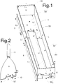
- the figure 1 illustrates a first embodiment of a container (20) and the figure 2 illustrates a first example of a scraper (9) being both part of a device according to the invention.
- the container and the scraper are preferably made of metal but they can also for example be made from a plastic or wood material.
- the container (20) is generally of parallelepipedal shape with a length L, a width l and a height H. It comprises a fully open top face (1) and an implementation face (6), which in this embodiment is formed by the lower face (6).
- the latter comprises a first surface (S4) of width l and length L2, which preferably will be equal to or greater than a quarter of the total surface of this lower face (6) of the container (20).
- a first opening (S1), of width 11 and length L1 is provided in the implementation face (6) of the container.
- the opening (S1) preferably extends between a side face (3) and the first surface (S4) of the implementation face (6) of the container (20).
- This implementation face (6) also comprises a second surface (S2) of width 12 and length L1 and a third surface (S3) of width 18 and length L1 which each run along the first opening (S1) over its entire length. length (L1).
- the container further comprises three other lateral faces (2), (4) and (5) which, like the lateral face (3), extend from the implementation face (6) towards the upper face (1).
- the widths 11, 12 and 18 of the respective surfaces (S1), (S2) and (S3) are preferably constant over their entire common length L1.
- the widths 12 and 18 respectively of (S2) and (S3) may be the same or different.
- the lateral face (3) which forms a vertical face of the container (20), has a third opening (S6) of width 13 which is at least equal, but preferably greater than 2 mm, to the width 11 of the opening (S1). These 2mm are obtained by having 1mm of each rising side of the third opening.
- the height H1 of the third opening (S6) is smaller than the height H of the container (20).
- the first opening (S1) opens into the third opening (S6).
- the openings (S1) and (S6) although of different widths, are centered relative to each other.
- the scraper (9) illustrated in figure 2 is provided with a handle (11) and has a side (10), opposite to the handle (11), which is profiled.
- the width 15 of the profiled side (10) of the scraper is preferably at least 2 mm smaller than the width of the interior of the container (20) for a reason which will be described below.
- the profiled side (10) of the scraper (9) has a second opening (10 ') which each extends over a fraction of said profiled side and which is located partially recessed over at least one width 14 and one height H2. This height H2 is at least 3 mm smaller than the height H1 of the opening (S6) of the lateral face (3) of the container (20).
- the width 14 of this second opening (10 ') is preferably at least 2 mm smaller than the width (11) of the first opening (S1) of the container (20). These 2mm are obtained by having 1mm of each rising side of the second opening.
- the height H1 of the third opening (S6) of the container is preferably at least 3 mm higher than the height H2 of the second opening on the side (10) of the scraper (9).
- the scraper is dimensioned so that it can be introduced into the container (20) via its upper face (1).
- the second opening (10 ') of the scraper is arranged to correspond with the first opening (S1) when the profiled side of the scraper is placed on the implementation face in a position ready to perform inside the container a translational movement to spread and scrape the pasty product.
- the container (20) is preferably equipped with a stop made preferably in two separate parts (7) and (8) of each other over a distance L4 at least 1cm greater than the width of the container in order to ensure the continuity of the at least one strip of pasty product (14) deposited on the support (13) when there are two supports (13) and (15) which intersect, as illustrated in FIG. figure 12 .
- the abutment portion (7) is of length L3 at most equal to the length L2 of the surface (S4) and the abutment portion (8) will be of length L5 at most equal to (L1) - (L4) -1cm.
- the portion (7) of the abutment will preferably start in alignment with the lateral face (5).
- the thickness E of the faces (2), (3), (4), (5), (6) of the container (20) and E1 of the scraper (9) are between 0.5 mm and 1, 5mm and less than the height H3 (see figure 12 ) of the at least one strip of pasty product (14) deposited on the support (13) which is equal to (E) + (H2) of the scraper (9).
- the Figures 3 and 4 illustrate a second embodiment of the device according to the invention.
- This embodiment makes it possible to deposit on a support two strips of pasty product.
- the implementation face (6) comprises two first openings (S1 and S1 ') which extend in parallel with each other.
- the scraper (9) also has two second openings (10 'and 10 ") and the lateral face (3) two third openings (S6 and S6'), the first and second openings respectively being separated by a distance 14 and 14 '.
- the second openings each extend over a fraction of said profiled side and are arranged to correspond with one of the first openings when the side scraper profile is placed on the implementation face in a position ready to perform the translational movement to spread and scrape the pasty product.
- Characteristics similar to those described above for the dimension of the first (S1 and S1 ') , second (10 'and 10 ") and third (S6 and S6 ') openings also apply to this embodiment.
- the container (20) illustrated in figure 3 is equipped with adjusting elements (12) of the stop (7), (8).
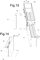
- adjustment elements are, for example, screws that pass through the stops and are applied to the lateral face of the support (13), as illustrated in FIG. figure 14 .
- the third openings (S6 and S6 ') could, if necessary, be formed by a single opening which spans the first two openings.
- the Figures 5 and 6 illustrate a third embodiment of the device according to the invention.
- This embodiment makes it possible to deposit on a support three parallel strips of pasty product.
- the implementation face (6) has three first openings (S1, S1 'and S1 ") and the container (20) illustrated in FIG. figure 5 is partially compartmentalized by means of partitions (30 and 31) which makes it possible to use a scraper (9) of smaller size with only a second opening (10 ').
- This embodiment of the invention is provided to limit the effort to be applied to the scraper (9) to form the pasty product strips.
- the Figures 7,8,9,10 and 11 illustrate, by way of example and in a nonlimiting manner, some other embodiments of scrapers (9) according to the invention.
- the scraper has a sawtooth profile on its side 10, which allows to apply a strip of pasty striated product.
- the scraper has a curved profile
- the scraper has a triangular profile
- the scraper has a profile in the shape of a house.
- the scraper comprises two second openings of different dimensions, which scraper can be used for masonry building elements that are inclined, such as for example window sills.
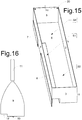
- the Figures 15 and 16 illustrate a fourth embodiment of a device according to the invention.
- the first opening (S1) runs along and is in direct contact with the lateral face (4) of the container (20).
- the second opening (10 ') on the scraper 9 is located on the left edge of the side (10), so as to correspond with the first opening when the profiled side of the scraper is placed on the implementation face in a position ready to perform the translation movement to spread and scrape the pasty product.
- the third opening (S6) is also located on the lateral edge of the lateral face 3.
- similar criteria as those described in Figures 1 and 2 for the size of the first, second and third apertures also apply to this embodiment.
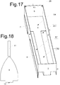
- the exemplary embodiment illustrated in figure 17 is different from that of the figure 15 in that the first openings (S1) and (S7) present on the underside (6) of the container (20) run along and are in direct contact with the side faces (2) and (4) of the same container respectively ( 20). It is also distinguished by the fact that the third openings are located at the ends of the lateral flank (3).
- the exemplary embodiment illustrated in figure 18 is different from that of the figure 4 in that the second openings are located on both the left and right side of the scraper.
- the Figures 19 and 20 illustrate a sixth embodiment of a device according to the invention.
- the surface (S4) is perpendicular to the implementation face where are located the surfaces (S2, S3 and S8) and the first openings (S1 and S7).
- the implementation face therefore extends vertically and not horizontally, as is the case in the other examples of production.
- This embodiment makes it possible to deposit two strips of pasty product on a support which extends vertically to for example form a joint between two juxtaposed blocks.
- criteria similar to those described in Figures 1 and 2 for the dimension of the first, second and third apertures also apply to this embodiment.
- the stop (7), (8) of the container (20) is positioned at the right side faces (2) and (3).
- the figure 12 illustrates the implementation of the method according to the invention. It shows the container (20) which rests on the support.
- a supply of pasty product, more particularly mortar (16) was introduced by the open face of the container and placed on the surface (S4).
- the scraper (9) was introduced via the open face into the container to thereby allow the mortar to be spread on the support 13 on which the container is placed.
- the scraper is positioned on the implementation face inside the container so that for the strip (14) of mortar to be spread, the second opening of the scraper corresponds to the first opening of the container.
- the scraper is placed in such a way on the implementation face that its side (10) extends in parallel with the lateral face (3).
- a mason will then place the scraper in the mortar pool to take a quantity of mortar. It will then impose on the scraper, inside the container, a translational movement which extends over at least the first opening (S1) and that while keeping the container in place on the support. This translational movement will allow to spread the mortar. When the mortar has, thanks to the translational movement, reached the first opening (S1), it will cross this first opening to reach the support 13. The presence of the second opening on the scraper and its positioning in front of the first opening will allow to correctly spread and dose the pasty product on the support. They will also allow scraping the spread product, to evacuate a surplus of applied product.
- the figure 12 also shows that the container has been moved relative to the support (13) to continue the application of the band (14).
- the pasty product strip that has just been applied passes through this third opening during the displacement of the container after the application of the strip.
- the applied band has a height (H2 + E) and a width l4. Since the height H1 of the third opening is greater than that of the second opening (H2) and the thickness (E) of the implementation face (H1> H2 + E), the band can traverse the third height opening.
- the strip can traverse in width the first and the second aperture. third opening. This allows to leave some clearance between the band and the container when moving the container along the support. This prevents the displacement of the container to damage the freshly applied band.
- the figure 13 illustrates the application, using the same container, two strips (14) of pasty product on a first support (13).
- a container and a scraper are used, as illustrated in Figures 3 and 4 .
- the container is provided with a stop (7 and 8) which is provided with adjusting elements (12) to correctly position the container relative to the support.
- the container shown in Figure13 is wide greater than that of the support (13) to precisely allow the adjustment of the stop. This setting is shown in figure 14 .
- the method and the device according to the invention thus make it possible to deposit on a support (13), for example a wall, one or more strips of mortar or glue through the partly open face of the container.
- the latter is preferably set back from the edge of the wall to prevent overflow and wastage of pasty product when placing bricks or blocks.
- a support for example a wall
- the latter is preferably set back from the edge of the wall to prevent overflow and wastage of pasty product when placing bricks or blocks.
- the higher the opening and / or wider the greater the amount of binder deposited on the support and therefore the height of the horizontal mortar joints can be easily adapted. It will simply be sufficient for the mason to have several containers and scrapers with different opening dimensions to be able to choose the one that will have the appropriate size of the band to be applied.
- the container and scraper, which make up the invention are indissociable and together achieve the goal. This allows a pasty product economy, speed of execution, cleanliness, ease of use, adaptation, manufacture and cleaning after use.
- the first surface (S4) of the container preferably allows contain a reserve of pasty product sufficient to deposit up to several meters of pasty product tape without having to refill the container with pasty product.
- a reserve of pasty product sufficient to deposit up to several meters of pasty product tape without having to refill the container with pasty product.
- the container is deposited pasty product inside this container on its bottom, ie on its underside and the side where it is not openwork.
- the amount of pasty product that can contain the container is sufficient to deposit on a support the at least one strip of pasty product of length greater than at least the length of the container but preferably at least one band several meters long.
- the container makes it possible to position the at least one strip of pasty product on the support with respect to at least one edge of this same support.
- the device composed of the container and the scraper, also makes it possible to deposit on a support at least one strip of pasty product with a thickness ranging from 2 to 30 mm, without having to modify the container.
- the side walls 2 and 4 of the container allow laterally guiding the scraper during its movement in the same container, while the implementation face can guide the scraper height.
- the size of the container makes it possible to present only a very small surface in contact with the at least one strip of pasty product, thus making it possible to avoid any problem of adhesion of pasty product to the container during demolding.
- the scraper is intended to spread the pasty product on the underside of the container and then by bearing on it and by leveling the same face, to form the at least one strip of pasty product to deposit on the support.
- the implementation face of the container and the scraper are of small thickness which limits the contact surface of the device with the pasty product and which prevents the device from getting dirty quickly and facilitates the demolding of the at least one strip of product pasty formed and deposited on the support using the device.
- the container is provided with at least one stop which when it is brought against the support, will deposit on the same support the at least one strip of pasty product at a predetermined distance from at least one edge of the support.
- the height of the container and therefore that of its lateral faces will be sufficient, ideally between 2 and 10 cm, to prevent the pasty product from coming out of this same container by passing over these same side faces when one goes move this same pasty product with the scraper into the container.
- the pasty product intended to fill the vertical joints of the masonry may be applied to the vertical wall of the blocks by means of a container specially arranged to deposit the at least one mortar strip in a vertical position.
- a container adapted to the type of brick allows to position, align and maintain them while with the container and the scraper is deposited the at least one strip of pasty product on their endisse. At this time the container will be positioned horizontally and will in one go to deposit the pasty product on several bricks at a time. The container can also bring all these bricks at once near the wall under construction.
- the container will be constructed of sheet metal but it could be made of plastic or any other material for its manufacture and use.
- the Figures 21, 22 and 23 illustrate three steps of depositing two strips of pasty product (16) on a vertical support using the container (20) illustrated in FIG. figure 19 and its scraper shown at the figure 20 .
- the Figures 24, 25, 26, 27 and 28 illustrate the chronology of the steps to deposit one or more strips of pasty product on a header of a series of bricks in one go.
- the empty container (22) of the Figure 24 will be filled with bricks (23) until it is full as shown in the Figure 25 . At this moment the bricks are positioned and kept aligned by the container.
- flanks (21) of the container (22) will be of height (H4) greater than the length (H5) of the bricks illustrated in FIG. figure 28 .
- the bottom of the container (20) is then placed on these flanks (21) and is no longer in contact with the bricks when depositing on the butt of bricks the at least one strip of pasty product.
Landscapes
- Engineering & Computer Science (AREA)
- Architecture (AREA)
- Civil Engineering (AREA)
- Structural Engineering (AREA)
- Mechanical Engineering (AREA)
- Basic Packing Technique (AREA)
Claims (14)
- Verfahren zum Anbringen mindestens einer Materialbahn (14) eines pastösen Produkts, insbesondere eines Bindemittels, auf einen Träger (13), insbesondere eine Mauer im Bau, wobei einen Behälter (20), der eine offene Fläche (1) und eine Durchführungsfläche (6) umfasst, mit einen pastösen Produkt zugeliefert wird, , wobei die offene Fläche der Durchführungsfläche gegenüberliegt, wobei die Durchführungsfläche mit mindestens einer ersten Öffnung (S1,S1',S1",S7) versehen ist, die sich über einen ersten Teil (L1) der Länge (L) dieser Durchführungsfläche erstreckt, wobei das pastöse Produkt auf den Träger aufgestrichen wird, indem man es die erste(n) Öffnung(en) durchqueren lässt und danach mithilfe eines Schabers (9), der durch die offene Fläche ins Innere des Behälters eingeführt wird, abgeschabt wird, wobei der Schaber eine profilierte Seite (10) derart beinhaltet, um mit mindestens einer zweiten Öffnung versehen zu sein, wobei sich die zweite(n) Öffnung(en) jede über einen Bruchteil der profilierten Seite erstrecken, und dem Schaber einer Translationsbewegung auferlegt wird, die sich über mindestens den ersten Teil erstreckt, während der Behälter auf dem Träger an der Stelle gehalten wird, dadurch gekennzeichnet, dass der Behälter mit pastösem Produkt mit Ablagern dieses pastösen Produkts auf einen zweiten Teil (S4) der Durchführungsfläche bereitgestellt wird, wobei der zweite Teil in der Richtung der Länge, bezogen auf den ersten Teil, versetzt ist, und dadurch, dass das pastöse Produkt ausgehend von dem zweiten Teil mithilfe des Schabers, der auf eine Weise konfiguriert ist, dass die zweite(n) Öffnung(en) auf eine Weise angeordnet sind, um jede mit einer der ersten Öffnungen übereinzustimmen, wenn die profilierte Seite des Schabers der Durchführungsfläche gegenüberliegt, in einer zum Aufstreichen des pastösen Produkts geeigneten Position auf den Träger aufgestrichen wird, und dadurch, dass der Schaber auf der Durchführungsfläche im Inneren des Behälters auf eine Weise positioniert wird, sodass für die aufzutragenden Materialbahn(en) eine oder mehrere zweite Öffnungen einer oder mehreren ersten Öffnungen entsprechen, wobei das pastöse Produkt während der Translationsbewegung des Schabers auf den Träger aufgestrichen wird, wobei das Aufstreichen des pastösen Produkts von einem Abschaben des aufgestrichenen Produkts gefolgt wird, um die mindestens eine Materialbahn mithilfe des Schabers zu bilden und einen Überschuss aufgetragenen Produkts zu entfernen.
- Verfahren nach Anspruch 1, dadurch gekennzeichnet, dass man einen Überschuss des beim Abschaben gesammelten pastösen Produkts auf diesen zweiten Teil zurückbringt, um dort deponiert zu werden.
- Verfahren nach Anspruch 1 oder 2, dadurch gekennzeichnet, dass der Behälter, nachdem die Materialbahn aufgestrichen und abgeschabt wurde, durch Aufheben in Bezug auf den Träger verschoben wird, um ihn danach auf den Träger auf eine Weise zurückzusetzen, um das Auftragen der Materialbahn fortzusetzen.
- Verfahren nach einem der Ansprüche 1 bis 3, dadurch gekennzeichnet, dass der Behälter eine Seitenfläche, versehen mit mindestens einer dritten Öffnung (S6,S6',S6") beinhaltet, die sich über einen Teil dieser Seitenfläche erstreckt, wobei jede der ersten und dritten Öffnungen auf eine Weise angeordnet sind, dass jede der dritten Öffnungen an mindestens einer der ersten Öffnungen ausgerichtet ist, und dadurch, dass der Behälter, nachdem die Materialbahn aufgestrichen und abgeschabt wurde, verschoben wird, indem man ihn auf dem Träger gleiten lässt, um danach das Auftragen der Materialbahn fortzusetzen.
- Vorrichtung, umfassend einen Behälter (20) und einen Schaber (9), wobei der Behälter eine offene Fläche (1) und eine Durchführungsfläche (6) umfasst, wobei die offene Fläche der Durchführungsfläche gegenüberliegt, wobei die Durchführungsfläche mit mindestens einer ersten Öffnung (S1,S1',S1",S7) versehen ist, die sich über einen ersten Teil (L1) der Länge (L) dieser Durchführungsfläche erstreckt, wobei der Schaber eine profilierte Fläche (10) auf eine Weise beinhaltet, um mit mindestens einer zweiten Öffnung versehen zu sein, die zweite(n) Öffnung(en) sich jede über einen Bruchteil der profilierten Fläche erstrecken, wobei die profilierte Fläche eine Größe aufweist, dimensioniert, um dem Schaber im Inneren des Behälters eine Translationsbewegung auferlegen zu können, die sich mindestens entlang der Länge des ersten Teils der Länge erstreckt, dadurch gekennzeichnet, dass die zweite(n) Öffnung(en) auf eine Weise angeordnet ist oder sind, um einer der ersten Öffnungen zu entsprechen, wenn die profilierte Seite des Schabers auf der Durchführungsfläche in einer Position platziert ist, die geeignet ist, die Translationsbewegung durchzuführen, um das pastöse Produkt aufzustreichen und abzuschaben, und dadurch, dass die Durchführungsfläche einen zweiten Teil (S4) beinhaltet, wobei der zweite Teil, bezogen auf den ersten Teil, in Richtung der Länge versetzt ist.
- Vorrichtung nach Anspruch 5, dadurch gekennzeichnet, dass der Behälter eine Seitenfläche (3), versehen mit mindestens einer dritten Öffnung (S6,S6',S6"), beinhaltet, die sich über einen Teil dieser Seitenfläche erstreckt, wobei jede der ersten und dritten Öffnungen auf eine Weise angeordnet sind, dass jede der dritten Öffnungen an mindestens einer der ersten Öffnungen ausgerichtet ist.
- Vorrichtung nach Anspruch 6, dadurch gekennzeichnet, dass jede dritte Öffnung über eine Größe (l3), größer als diejenige (l1) der ersten Öffnung, an der sie ausgerichtet ist, verfügt.
- Vorrichtung nach Anspruch 7, dadurch gekennzeichnet, dass jede dritte Öffnung über eine Größe, mindestens 2 mm größer als diejenige der ersten Öffnung, an der sie ausgerichtet ist, verfügt.
- Vorrichtung nach einem der Ansprüche 5 bis 8, dadurch gekennzeichnet, dass jede dritte Öffnung sich auf einer Höhe (H1) erstreckt, die größer ist als diejenige (H2), auf der sich die zweite(n) Öffnung(en) erstrecken.
- Vorrichtung nach einem der Ansprüche 5 bis 9, dadurch gekennzeichnet, dass der zweite Teil (S4) der Durchführungsfläche des Behälters über eine Oberfläche verfügt, die gleich oder größer ist als das Viertel der Gesamtoberfläche der Durchführungsfläche.
- Vorrichtung nach einem der Ansprüche 5 bis 10, dadurch gekennzeichnet, dass der Behälter (20) mit einem Anschlagselement (7, 8) ausgestattet ist, das an einer außeren seitlichen Flanke des Behälters angebracht ist.
- Vorrichtung nach Anspruch 11, dadurch gekennzeichnet, dass das Anschlagselement in zwei Teilen, voneinander durch eine Länge (L4), größer als die Größe (l13) des Behälters, beabstandet realisiert ist.
- Vorrichtung nach Anspruch 11 oder 12, dadurch gekennzeichnet, dass das Anschlagselement (7, 8) mithilfe von Einstellungselementen (12) einstellbar ist.
- Vorrichtung nach einem der Ansprüche 5 bis 13, dadurch gekennzeichnet, dass sie ebenfalls ein Behältnis (22) beinhaltet, ausgelegt, um mehrere Ziegelsteine (23) zu positionieren und ausgerichtet zu halten, auf welchen Ziegelsteinen oder auf welches Behältnis der Behälter deponiert werden kann.
Applications Claiming Priority (1)
| Application Number | Priority Date | Filing Date | Title |
|---|---|---|---|
| BE2016/0002A BE1023780B1 (fr) | 2016-01-14 | 2016-01-14 | Dispositif de dosage et de positionnement de produit pateux |
Publications (2)
| Publication Number | Publication Date |
|---|---|
| EP3192944A1 EP3192944A1 (de) | 2017-07-19 |
| EP3192944B1 true EP3192944B1 (de) | 2018-11-07 |
Family
ID=55357821
Family Applications (1)
| Application Number | Title | Priority Date | Filing Date |
|---|---|---|---|
| EP17000034.3A Active EP3192944B1 (de) | 2016-01-14 | 2017-01-10 | Verfahren und vorrichtung zur aufbringung eines pastösen produkts |
Country Status (2)
| Country | Link |
|---|---|
| EP (1) | EP3192944B1 (de) |
| BE (1) | BE1023780B1 (de) |
Families Citing this family (3)
| Publication number | Priority date | Publication date | Assignee | Title |
|---|---|---|---|---|
| CN108412216A (zh) * | 2018-04-28 | 2018-08-17 | 中建局集团第二建筑有限公司 | 一种砌筑时摊铺砂浆的工具组件及其施工方法 |
| DE102021106224A1 (de) | 2021-03-15 | 2022-09-15 | Sven Brunner | Werkzeug zum Auftragen einer bauchemischen Masse, insbesondere einer Spachtelmasse, einer Putzschicht, eines Klebers oder dergleichen |
| BE1031744B1 (fr) | 2023-06-28 | 2025-02-05 | Trapani Agostino Di | Elément de construction |
Family Cites Families (8)
| Publication number | Priority date | Publication date | Assignee | Title |
|---|---|---|---|---|
| US1556616A (en) * | 1922-06-05 | 1925-10-13 | Landkamer Levi | Mortar stringer |
| DE829789C (de) * | 1949-09-27 | 1952-01-28 | Albert Feifel | Vorrichtung zum Auftragen einer gleichmaessig starken Moertelschicht auf waagrechte Mauerflaechen |
| DE1057321B (de) * | 1955-08-17 | 1959-05-14 | Mjoelby Nya Mek Ab | Moertelauftraggeraet |
| FR2560912A1 (fr) * | 1984-03-09 | 1985-09-13 | Koehl Francois | Systeme de jointoiement de maconnerie de blocs pour joints horizontaux et verticaux |
| US4709526A (en) * | 1986-04-21 | 1987-12-01 | John T. Crumby | Mortar application template |
| US5035352A (en) * | 1988-03-04 | 1991-07-30 | Frank Mania | Adjustable apparatus for spreading mortar and method therefor |
| FR2630485B1 (fr) * | 1988-04-21 | 1990-08-24 | Jeudon Daniel | Distributeur-repartiteur de rubans de mortier |
| FR2643834B1 (fr) * | 1989-03-06 | 1991-08-30 | Authie Paul | Appareil pour realiser rapidement des joints de maconnerie de caracteristiques optimales, utilisable plus generalement pour deposer sur un support et former des mortiers, pates et produits visqueux, granuleux ou pulverulents |
-
2016
- 2016-01-14 BE BE2016/0002A patent/BE1023780B1/fr not_active IP Right Cessation
-
2017
- 2017-01-10 EP EP17000034.3A patent/EP3192944B1/de active Active
Non-Patent Citations (1)
| Title |
|---|
| None * |
Also Published As
| Publication number | Publication date |
|---|---|
| BE1023780A1 (fr) | 2017-07-24 |
| BE1023780B1 (fr) | 2017-07-25 |
| EP3192944A1 (de) | 2017-07-19 |
Similar Documents
| Publication | Publication Date | Title |
|---|---|---|
| EP3192944B1 (de) | Verfahren und vorrichtung zur aufbringung eines pastösen produkts | |
| WO2018087474A1 (fr) | Installation de fabrication additive a base de poudre a dispositif de nettoyage par soufflage | |
| EP0143043B1 (de) | Gleitschalungsfertiger mit zwei Formplatten zum Erstellen von Betonstrassendecken | |
| WO2018087476A1 (fr) | Installation de fabrication additive a base de poudre a dispositif de nettoyage par raclage | |
| WO2018087475A1 (fr) | Installation de fabrication additive a base de poudre a dispositif de nettoyage par brossage | |
| FR2490263A1 (fr) | Appareil pour la distribution d'une matiere pateuse sous forme de bandes | |
| FR2988560A1 (fr) | Dispositif de pose d'un film plastique pour paillage | |
| EP3899162B1 (de) | Überhangselement | |
| FR3079253A1 (fr) | Dispositif de pose de mortier sur des blocs de maconnerie creux a bords minces | |
| FR2987222A1 (fr) | Dispositif mecanise pour planter des plants | |
| WO2006075111A1 (fr) | Dispositif de depose reguliere de mortier sur des blocs de maconnerie | |
| FR3083252A1 (fr) | Kit de realisation de mannequins de coffrage | |
| EP0514300A2 (de) | Verfahren und Vorrichtung zum Verlegen von Bodenbelägen mittels Platten | |
| EP2069583B1 (de) | Aus einem Bauelement und einem Maurerwerkzeug bestehende Anordnung | |
| FR2975326A1 (fr) | Auge de macon avec un rangement d'outils | |
| FR2636651A1 (fr) | Joint de dilatation pour dallage en beton | |
| FR3152735A1 (fr) | dispositif de nettoyage d’un moule de coulage d’un élément en matériau à base d’eau et de liant hydraulique, et procédé de nettoyage correspondant | |
| EP2384993A1 (de) | Plastikabdeckung zum Abdecken von Chargiermulden, ihre Anwendung und Kit, bestehend aus einer solchen Abdeckung und mehreren Sets dieser Mulden | |
| EP3091142B1 (de) | Gerät zur aufbringung eines flüssigen ausbesserungsprodukts | |
| FR2897629A1 (fr) | Dispositif de pose de mortier de jointoiement pour briques ou autres blocs de construction | |
| FR2902293A1 (fr) | Procede de division volumetrique de pate et son dispositif de mise en oeuvre | |
| FR3018733A1 (fr) | Dispositif d'egouttage et de pose d'un outil de peinture dans un pot. | |
| FR2860824A1 (fr) | Machine a enfiler des lames de tablier de volets roulants | |
| FR3013065A1 (fr) | Dispositif pour la pose de revetements de sols et murs pour angles rentrants | |
| FR2838467A1 (fr) | Dispositif pour l'application lineaire de produit pateux, notamment de mortier |
Legal Events
| Date | Code | Title | Description |
|---|---|---|---|
| PUAI | Public reference made under article 153(3) epc to a published international application that has entered the european phase |
Free format text: ORIGINAL CODE: 0009012 |
|
| STAA | Information on the status of an ep patent application or granted ep patent |
Free format text: STATUS: THE APPLICATION HAS BEEN PUBLISHED |
|
| AK | Designated contracting states |
Kind code of ref document: A1 Designated state(s): AL AT BE BG CH CY CZ DE DK EE ES FI FR GB GR HR HU IE IS IT LI LT LU LV MC MK MT NL NO PL PT RO RS SE SI SK SM TR |
|
| AX | Request for extension of the european patent |
Extension state: BA ME |
|
| STAA | Information on the status of an ep patent application or granted ep patent |
Free format text: STATUS: REQUEST FOR EXAMINATION WAS MADE |
|
| 17P | Request for examination filed |
Effective date: 20180111 |
|
| RBV | Designated contracting states (corrected) |
Designated state(s): AL AT BE BG CH CY CZ DE DK EE ES FI FR GB GR HR HU IE IS IT LI LT LU LV MC MK MT NL NO PL PT RO RS SE SI SK SM TR |
|
| GRAP | Despatch of communication of intention to grant a patent |
Free format text: ORIGINAL CODE: EPIDOSNIGR1 |
|
| STAA | Information on the status of an ep patent application or granted ep patent |
Free format text: STATUS: GRANT OF PATENT IS INTENDED |
|
| INTG | Intention to grant announced |
Effective date: 20180518 |
|
| GRAS | Grant fee paid |
Free format text: ORIGINAL CODE: EPIDOSNIGR3 |
|
| GRAA | (expected) grant |
Free format text: ORIGINAL CODE: 0009210 |
|
| STAA | Information on the status of an ep patent application or granted ep patent |
Free format text: STATUS: THE PATENT HAS BEEN GRANTED |
|
| AK | Designated contracting states |
Kind code of ref document: B1 Designated state(s): AL AT BE BG CH CY CZ DE DK EE ES FI FR GB GR HR HU IE IS IT LI LT LU LV MC MK MT NL NO PL PT RO RS SE SI SK SM TR |
|
| REG | Reference to a national code |
Ref country code: GB Ref legal event code: FG4D Free format text: NOT ENGLISH |
|
| REG | Reference to a national code |
Ref country code: AT Ref legal event code: REF Ref document number: 1062213 Country of ref document: AT Kind code of ref document: T Effective date: 20181115 Ref country code: CH Ref legal event code: EP |
|
| REG | Reference to a national code |
Ref country code: DE Ref legal event code: R096 Ref document number: 602017000770 Country of ref document: DE |
|
| REG | Reference to a national code |
Ref country code: IE Ref legal event code: FG4D Free format text: LANGUAGE OF EP DOCUMENT: FRENCH |
|
| REG | Reference to a national code |
Ref country code: NL Ref legal event code: FP |
|
| REG | Reference to a national code |
Ref country code: LT Ref legal event code: MG4D |
|
| PGFP | Annual fee paid to national office [announced via postgrant information from national office to epo] |
Ref country code: LU Payment date: 20190130 Year of fee payment: 3 |
|
| REG | Reference to a national code |
Ref country code: AT Ref legal event code: MK05 Ref document number: 1062213 Country of ref document: AT Kind code of ref document: T Effective date: 20181107 |
|
| PG25 | Lapsed in a contracting state [announced via postgrant information from national office to epo] |
Ref country code: LV Free format text: LAPSE BECAUSE OF FAILURE TO SUBMIT A TRANSLATION OF THE DESCRIPTION OR TO PAY THE FEE WITHIN THE PRESCRIBED TIME-LIMIT Effective date: 20181107 Ref country code: FI Free format text: LAPSE BECAUSE OF FAILURE TO SUBMIT A TRANSLATION OF THE DESCRIPTION OR TO PAY THE FEE WITHIN THE PRESCRIBED TIME-LIMIT Effective date: 20181107 Ref country code: ES Free format text: LAPSE BECAUSE OF FAILURE TO SUBMIT A TRANSLATION OF THE DESCRIPTION OR TO PAY THE FEE WITHIN THE PRESCRIBED TIME-LIMIT Effective date: 20181107 Ref country code: IS Free format text: LAPSE BECAUSE OF FAILURE TO SUBMIT A TRANSLATION OF THE DESCRIPTION OR TO PAY THE FEE WITHIN THE PRESCRIBED TIME-LIMIT Effective date: 20190307 Ref country code: AT Free format text: LAPSE BECAUSE OF FAILURE TO SUBMIT A TRANSLATION OF THE DESCRIPTION OR TO PAY THE FEE WITHIN THE PRESCRIBED TIME-LIMIT Effective date: 20181107 Ref country code: BG Free format text: LAPSE BECAUSE OF FAILURE TO SUBMIT A TRANSLATION OF THE DESCRIPTION OR TO PAY THE FEE WITHIN THE PRESCRIBED TIME-LIMIT Effective date: 20190207 Ref country code: HR Free format text: LAPSE BECAUSE OF FAILURE TO SUBMIT A TRANSLATION OF THE DESCRIPTION OR TO PAY THE FEE WITHIN THE PRESCRIBED TIME-LIMIT Effective date: 20181107 Ref country code: LT Free format text: LAPSE BECAUSE OF FAILURE TO SUBMIT A TRANSLATION OF THE DESCRIPTION OR TO PAY THE FEE WITHIN THE PRESCRIBED TIME-LIMIT Effective date: 20181107 Ref country code: NO Free format text: LAPSE BECAUSE OF FAILURE TO SUBMIT A TRANSLATION OF THE DESCRIPTION OR TO PAY THE FEE WITHIN THE PRESCRIBED TIME-LIMIT Effective date: 20190207 |
|
| PGFP | Annual fee paid to national office [announced via postgrant information from national office to epo] |
Ref country code: FR Payment date: 20190122 Year of fee payment: 3 Ref country code: DE Payment date: 20190131 Year of fee payment: 3 |
|
| PG25 | Lapsed in a contracting state [announced via postgrant information from national office to epo] |
Ref country code: PT Free format text: LAPSE BECAUSE OF FAILURE TO SUBMIT A TRANSLATION OF THE DESCRIPTION OR TO PAY THE FEE WITHIN THE PRESCRIBED TIME-LIMIT Effective date: 20190307 Ref country code: GR Free format text: LAPSE BECAUSE OF FAILURE TO SUBMIT A TRANSLATION OF THE DESCRIPTION OR TO PAY THE FEE WITHIN THE PRESCRIBED TIME-LIMIT Effective date: 20190208 Ref country code: RS Free format text: LAPSE BECAUSE OF FAILURE TO SUBMIT A TRANSLATION OF THE DESCRIPTION OR TO PAY THE FEE WITHIN THE PRESCRIBED TIME-LIMIT Effective date: 20181107 Ref country code: SE Free format text: LAPSE BECAUSE OF FAILURE TO SUBMIT A TRANSLATION OF THE DESCRIPTION OR TO PAY THE FEE WITHIN THE PRESCRIBED TIME-LIMIT Effective date: 20181107 Ref country code: AL Free format text: LAPSE BECAUSE OF FAILURE TO SUBMIT A TRANSLATION OF THE DESCRIPTION OR TO PAY THE FEE WITHIN THE PRESCRIBED TIME-LIMIT Effective date: 20181107 |
|
| PG25 | Lapsed in a contracting state [announced via postgrant information from national office to epo] |
Ref country code: CZ Free format text: LAPSE BECAUSE OF FAILURE TO SUBMIT A TRANSLATION OF THE DESCRIPTION OR TO PAY THE FEE WITHIN THE PRESCRIBED TIME-LIMIT Effective date: 20181107 Ref country code: IT Free format text: LAPSE BECAUSE OF FAILURE TO SUBMIT A TRANSLATION OF THE DESCRIPTION OR TO PAY THE FEE WITHIN THE PRESCRIBED TIME-LIMIT Effective date: 20181107 Ref country code: DK Free format text: LAPSE BECAUSE OF FAILURE TO SUBMIT A TRANSLATION OF THE DESCRIPTION OR TO PAY THE FEE WITHIN THE PRESCRIBED TIME-LIMIT Effective date: 20181107 Ref country code: PL Free format text: LAPSE BECAUSE OF FAILURE TO SUBMIT A TRANSLATION OF THE DESCRIPTION OR TO PAY THE FEE WITHIN THE PRESCRIBED TIME-LIMIT Effective date: 20181107 |
|
| REG | Reference to a national code |
Ref country code: DE Ref legal event code: R097 Ref document number: 602017000770 Country of ref document: DE |
|
| PG25 | Lapsed in a contracting state [announced via postgrant information from national office to epo] |
Ref country code: SK Free format text: LAPSE BECAUSE OF FAILURE TO SUBMIT A TRANSLATION OF THE DESCRIPTION OR TO PAY THE FEE WITHIN THE PRESCRIBED TIME-LIMIT Effective date: 20181107 Ref country code: SM Free format text: LAPSE BECAUSE OF FAILURE TO SUBMIT A TRANSLATION OF THE DESCRIPTION OR TO PAY THE FEE WITHIN THE PRESCRIBED TIME-LIMIT Effective date: 20181107 Ref country code: EE Free format text: LAPSE BECAUSE OF FAILURE TO SUBMIT A TRANSLATION OF THE DESCRIPTION OR TO PAY THE FEE WITHIN THE PRESCRIBED TIME-LIMIT Effective date: 20181107 Ref country code: RO Free format text: LAPSE BECAUSE OF FAILURE TO SUBMIT A TRANSLATION OF THE DESCRIPTION OR TO PAY THE FEE WITHIN THE PRESCRIBED TIME-LIMIT Effective date: 20181107 Ref country code: MC Free format text: LAPSE BECAUSE OF FAILURE TO SUBMIT A TRANSLATION OF THE DESCRIPTION OR TO PAY THE FEE WITHIN THE PRESCRIBED TIME-LIMIT Effective date: 20181107 |
|
| PLBE | No opposition filed within time limit |
Free format text: ORIGINAL CODE: 0009261 |
|
| STAA | Information on the status of an ep patent application or granted ep patent |
Free format text: STATUS: NO OPPOSITION FILED WITHIN TIME LIMIT |
|
| 26N | No opposition filed |
Effective date: 20190808 |
|
| REG | Reference to a national code |
Ref country code: IE Ref legal event code: MM4A |
|
| PG25 | Lapsed in a contracting state [announced via postgrant information from national office to epo] |
Ref country code: SI Free format text: LAPSE BECAUSE OF FAILURE TO SUBMIT A TRANSLATION OF THE DESCRIPTION OR TO PAY THE FEE WITHIN THE PRESCRIBED TIME-LIMIT Effective date: 20181107 |
|
| PG25 | Lapsed in a contracting state [announced via postgrant information from national office to epo] |
Ref country code: IE Free format text: LAPSE BECAUSE OF NON-PAYMENT OF DUE FEES Effective date: 20190110 |
|
| PG25 | Lapsed in a contracting state [announced via postgrant information from national office to epo] |
Ref country code: TR Free format text: LAPSE BECAUSE OF FAILURE TO SUBMIT A TRANSLATION OF THE DESCRIPTION OR TO PAY THE FEE WITHIN THE PRESCRIBED TIME-LIMIT Effective date: 20181107 |
|
| PG25 | Lapsed in a contracting state [announced via postgrant information from national office to epo] |
Ref country code: MT Free format text: LAPSE BECAUSE OF FAILURE TO SUBMIT A TRANSLATION OF THE DESCRIPTION OR TO PAY THE FEE WITHIN THE PRESCRIBED TIME-LIMIT Effective date: 20181107 |
|
| REG | Reference to a national code |
Ref country code: DE Ref legal event code: R119 Ref document number: 602017000770 Country of ref document: DE |
|
| REG | Reference to a national code |
Ref country code: CH Ref legal event code: PL |
|
| REG | Reference to a national code |
Ref country code: NL Ref legal event code: MM Effective date: 20200201 |
|
| PG25 | Lapsed in a contracting state [announced via postgrant information from national office to epo] |
Ref country code: FR Free format text: LAPSE BECAUSE OF NON-PAYMENT OF DUE FEES Effective date: 20200131 Ref country code: NL Free format text: LAPSE BECAUSE OF NON-PAYMENT OF DUE FEES Effective date: 20200201 Ref country code: LU Free format text: LAPSE BECAUSE OF NON-PAYMENT OF DUE FEES Effective date: 20200110 Ref country code: DE Free format text: LAPSE BECAUSE OF NON-PAYMENT OF DUE FEES Effective date: 20200801 |
|
| PG25 | Lapsed in a contracting state [announced via postgrant information from national office to epo] |
Ref country code: CH Free format text: LAPSE BECAUSE OF NON-PAYMENT OF DUE FEES Effective date: 20200131 Ref country code: LI Free format text: LAPSE BECAUSE OF NON-PAYMENT OF DUE FEES Effective date: 20200131 |
|
| PG25 | Lapsed in a contracting state [announced via postgrant information from national office to epo] |
Ref country code: CY Free format text: LAPSE BECAUSE OF FAILURE TO SUBMIT A TRANSLATION OF THE DESCRIPTION OR TO PAY THE FEE WITHIN THE PRESCRIBED TIME-LIMIT Effective date: 20181107 |
|
| PG25 | Lapsed in a contracting state [announced via postgrant information from national office to epo] |
Ref country code: HU Free format text: LAPSE BECAUSE OF FAILURE TO SUBMIT A TRANSLATION OF THE DESCRIPTION OR TO PAY THE FEE WITHIN THE PRESCRIBED TIME-LIMIT; INVALID AB INITIO Effective date: 20170110 |
|
| GBPC | Gb: european patent ceased through non-payment of renewal fee |
Effective date: 20210110 |
|
| PG25 | Lapsed in a contracting state [announced via postgrant information from national office to epo] |
Ref country code: GB Free format text: LAPSE BECAUSE OF NON-PAYMENT OF DUE FEES Effective date: 20210110 |
|
| PG25 | Lapsed in a contracting state [announced via postgrant information from national office to epo] |
Ref country code: MK Free format text: LAPSE BECAUSE OF FAILURE TO SUBMIT A TRANSLATION OF THE DESCRIPTION OR TO PAY THE FEE WITHIN THE PRESCRIBED TIME-LIMIT Effective date: 20181107 |
|
| P01 | Opt-out of the competence of the unified patent court (upc) registered |
Effective date: 20230521 |
|
| PGFP | Annual fee paid to national office [announced via postgrant information from national office to epo] |
Ref country code: BE Payment date: 20260107 Year of fee payment: 10 |