EP3191230B1 - Verfahren und vorrichtung zum intermittierenden beschichten - Google Patents
Verfahren und vorrichtung zum intermittierenden beschichten Download PDFInfo
- Publication number
- EP3191230B1 EP3191230B1 EP15750249.3A EP15750249A EP3191230B1 EP 3191230 B1 EP3191230 B1 EP 3191230B1 EP 15750249 A EP15750249 A EP 15750249A EP 3191230 B1 EP3191230 B1 EP 3191230B1
- Authority
- EP
- European Patent Office
- Prior art keywords
- nozzle
- flexible element
- actuator
- passage opening
- coating
- Prior art date
- Legal status (The legal status is an assumption and is not a legal conclusion. Google has not performed a legal analysis and makes no representation as to the accuracy of the status listed.)
- Active
Links
Images




Classifications
-
- H—ELECTRICITY
- H01—ELECTRIC ELEMENTS
- H01M—PROCESSES OR MEANS, e.g. BATTERIES, FOR THE DIRECT CONVERSION OF CHEMICAL ENERGY INTO ELECTRICAL ENERGY
- H01M4/00—Electrodes
- H01M4/02—Electrodes composed of, or comprising, active material
- H01M4/04—Processes of manufacture in general
- H01M4/0402—Methods of deposition of the material
- H01M4/0404—Methods of deposition of the material by coating on electrode collectors
-
- B—PERFORMING OPERATIONS; TRANSPORTING
- B05—SPRAYING OR ATOMISING IN GENERAL; APPLYING FLUENT MATERIALS TO SURFACES, IN GENERAL
- B05C—APPARATUS FOR APPLYING FLUENT MATERIALS TO SURFACES, IN GENERAL
- B05C11/00—Component parts, details or accessories not specifically provided for in groups B05C1/00 - B05C9/00
- B05C11/10—Storage, supply or control of liquid or other fluent material; Recovery of excess liquid or other fluent material
- B05C11/1002—Means for controlling supply, i.e. flow or pressure, of liquid or other fluent material to the applying apparatus, e.g. valves
- B05C11/1034—Means for controlling supply, i.e. flow or pressure, of liquid or other fluent material to the applying apparatus, e.g. valves specially designed for conducting intermittent application of small quantities, e.g. drops, of coating material
-
- B—PERFORMING OPERATIONS; TRANSPORTING
- B05—SPRAYING OR ATOMISING IN GENERAL; APPLYING FLUENT MATERIALS TO SURFACES, IN GENERAL
- B05C—APPARATUS FOR APPLYING FLUENT MATERIALS TO SURFACES, IN GENERAL
- B05C11/00—Component parts, details or accessories not specifically provided for in groups B05C1/00 - B05C9/00
- B05C11/10—Storage, supply or control of liquid or other fluent material; Recovery of excess liquid or other fluent material
- B05C11/1047—Apparatus or installations for supplying liquid or other fluent material comprising a buffer container or an accumulator between the supply source and the applicator
-
- B—PERFORMING OPERATIONS; TRANSPORTING
- B05—SPRAYING OR ATOMISING IN GENERAL; APPLYING FLUENT MATERIALS TO SURFACES, IN GENERAL
- B05C—APPARATUS FOR APPLYING FLUENT MATERIALS TO SURFACES, IN GENERAL
- B05C5/00—Apparatus in which liquid or other fluent material is projected, poured or allowed to flow on to the surface of the work
- B05C5/02—Apparatus in which liquid or other fluent material is projected, poured or allowed to flow on to the surface of the work the liquid or other fluent material being discharged through an outlet orifice by pressure, e.g. from an outlet device in contact or almost in contact, with the work
- B05C5/0254—Coating heads with slot-shaped outlet
- B05C5/0258—Coating heads with slot-shaped outlet flow controlled, e.g. by a valve
-
- B—PERFORMING OPERATIONS; TRANSPORTING
- B05—SPRAYING OR ATOMISING IN GENERAL; APPLYING FLUENT MATERIALS TO SURFACES, IN GENERAL
- B05C—APPARATUS FOR APPLYING FLUENT MATERIALS TO SURFACES, IN GENERAL
- B05C9/00—Apparatus or plant for applying liquid or other fluent material to surfaces by means not covered by any preceding group, or in which the means of applying the liquid or other fluent material is not important
- B05C9/06—Apparatus or plant for applying liquid or other fluent material to surfaces by means not covered by any preceding group, or in which the means of applying the liquid or other fluent material is not important for applying two different liquids or other fluent materials, or the same liquid or other fluent material twice, to the same side of the work
-
- H—ELECTRICITY
- H01—ELECTRIC ELEMENTS
- H01M—PROCESSES OR MEANS, e.g. BATTERIES, FOR THE DIRECT CONVERSION OF CHEMICAL ENERGY INTO ELECTRICAL ENERGY
- H01M10/00—Secondary cells; Manufacture thereof
- H01M10/05—Accumulators with non-aqueous electrolyte
- H01M10/052—Li-accumulators
- H01M10/0525—Rocking-chair batteries, i.e. batteries with lithium insertion or intercalation in both electrodes; Lithium-ion batteries
-
- H—ELECTRICITY
- H01—ELECTRIC ELEMENTS
- H01M—PROCESSES OR MEANS, e.g. BATTERIES, FOR THE DIRECT CONVERSION OF CHEMICAL ENERGY INTO ELECTRICAL ENERGY
- H01M4/00—Electrodes
- H01M4/02—Electrodes composed of, or comprising, active material
- H01M4/04—Processes of manufacture in general
- H01M4/0402—Methods of deposition of the material
- H01M4/0419—Methods of deposition of the material involving spraying
-
- H—ELECTRICITY
- H01—ELECTRIC ELEMENTS
- H01M—PROCESSES OR MEANS, e.g. BATTERIES, FOR THE DIRECT CONVERSION OF CHEMICAL ENERGY INTO ELECTRICAL ENERGY
- H01M4/00—Electrodes
- H01M4/02—Electrodes composed of, or comprising, active material
- H01M4/13—Electrodes for accumulators with non-aqueous electrolyte, e.g. for lithium-accumulators; Processes of manufacture thereof
- H01M4/139—Processes of manufacture
-
- H—ELECTRICITY
- H01—ELECTRIC ELEMENTS
- H01M—PROCESSES OR MEANS, e.g. BATTERIES, FOR THE DIRECT CONVERSION OF CHEMICAL ENERGY INTO ELECTRICAL ENERGY
- H01M4/00—Electrodes
- H01M4/02—Electrodes composed of, or comprising, active material
- H01M4/62—Selection of inactive substances as ingredients for active masses, e.g. binders, fillers
- H01M4/621—Binders
- H01M4/622—Binders being polymers
-
- B—PERFORMING OPERATIONS; TRANSPORTING
- B05—SPRAYING OR ATOMISING IN GENERAL; APPLYING FLUENT MATERIALS TO SURFACES, IN GENERAL
- B05D—PROCESSES FOR APPLYING FLUENT MATERIALS TO SURFACES, IN GENERAL
- B05D1/00—Processes for applying liquids or other fluent materials
- B05D1/26—Processes for applying liquids or other fluent materials performed by applying the liquid or other fluent material from an outlet device in contact with, or almost in contact with, the surface
-
- B—PERFORMING OPERATIONS; TRANSPORTING
- B05—SPRAYING OR ATOMISING IN GENERAL; APPLYING FLUENT MATERIALS TO SURFACES, IN GENERAL
- B05D—PROCESSES FOR APPLYING FLUENT MATERIALS TO SURFACES, IN GENERAL
- B05D7/00—Processes, other than flocking, specially adapted for applying liquids or other fluent materials to particular surfaces or for applying particular liquids or other fluent materials
- B05D7/50—Multilayers
- B05D7/52—Two layers
- B05D7/54—No clear coat specified
- B05D7/542—No clear coat specified the two layers being cured or baked together
- B05D7/5423—No clear coat specified the two layers being cured or baked together the two layers being applied simultaneously
-
- H—ELECTRICITY
- H01—ELECTRIC ELEMENTS
- H01M—PROCESSES OR MEANS, e.g. BATTERIES, FOR THE DIRECT CONVERSION OF CHEMICAL ENERGY INTO ELECTRICAL ENERGY
- H01M10/00—Secondary cells; Manufacture thereof
- H01M10/05—Accumulators with non-aqueous electrolyte
- H01M10/052—Li-accumulators
-
- H—ELECTRICITY
- H01—ELECTRIC ELEMENTS
- H01M—PROCESSES OR MEANS, e.g. BATTERIES, FOR THE DIRECT CONVERSION OF CHEMICAL ENERGY INTO ELECTRICAL ENERGY
- H01M4/00—Electrodes
- H01M4/02—Electrodes composed of, or comprising, active material
- H01M4/04—Processes of manufacture in general
- H01M4/0402—Methods of deposition of the material
- H01M4/0414—Methods of deposition of the material by screen printing
-
- H—ELECTRICITY
- H01—ELECTRIC ELEMENTS
- H01M—PROCESSES OR MEANS, e.g. BATTERIES, FOR THE DIRECT CONVERSION OF CHEMICAL ENERGY INTO ELECTRICAL ENERGY
- H01M6/00—Primary cells; Manufacture thereof
- H01M6/40—Printed batteries, e.g. thin film batteries
-
- Y—GENERAL TAGGING OF NEW TECHNOLOGICAL DEVELOPMENTS; GENERAL TAGGING OF CROSS-SECTIONAL TECHNOLOGIES SPANNING OVER SEVERAL SECTIONS OF THE IPC; TECHNICAL SUBJECTS COVERED BY FORMER USPC CROSS-REFERENCE ART COLLECTIONS [XRACs] AND DIGESTS
- Y02—TECHNOLOGIES OR APPLICATIONS FOR MITIGATION OR ADAPTATION AGAINST CLIMATE CHANGE
- Y02E—REDUCTION OF GREENHOUSE GAS [GHG] EMISSIONS, RELATED TO ENERGY GENERATION, TRANSMISSION OR DISTRIBUTION
- Y02E60/00—Enabling technologies; Technologies with a potential or indirect contribution to GHG emissions mitigation
- Y02E60/10—Energy storage using batteries
Definitions
- the invention relates to a method and apparatus for intermittently coating a moving substrate.
- a device for intermittently applying adhesive to a continuously moving body is known.
- a method is disclosed which supplies a hot melt to a nozzle and applies it to a continuously running substrate. It is described that the supply of hot melt to the nozzle is interrupted if no coating is to be produced. By repeating this process, a substrate is intermittently coated.
- intermittent coating is achieved by increasing the coating gap between the nozzle and the substrate with each coating interruption.
- the still existing after-run of the coating material wets the die lips, which leads to an elevation of the starting edge when approaching the substrate again (arrester foil).
- a disadvantage of this approach is that caused by the movement of the nozzle and the placement of the wetted nozzle lips on the substrate, vibrations in the substrate, which in turn affect the distance of the nozzle lips to the substrate. Demenschend it is not possible to realize a continuous wet film thickness.
- Secondary lithium-ion batteries are based on an array of multiple electrochemical cells.
- the electrodes in an electrochemical cell each comprise an active material from which during operation of the electrochemical cell Lithium ions are intercalated into the electrodes.
- the active material lithium-containing composite oxide, preferably LiCoO 2 , LiFePO 4 , LiNi 1/3 Co 1/3 Mn 1/3 O 2 (NCM) or LiNi 0.8 Co 0.15 Al 0.05 O 2 (NCA), mesoporous titanium oxide, and conductive carbon black, graphite or the like in the positive electrode (anode). used.
- Suitable coating materials and their preparation are known and are hereby incorporated by reference into the application.
- the polymer binder required for the cathode or anode coating composition (coating material) is dissolved, for example, in 5-10% fluoroelastomer homopolymers or copolymers in N-methylpyrrolidone (NMP) and the resulting polymer solution with the cathodes - or anode-specific additives such as lithium intercalatable metal oxides or lithium intercalatable carbons (carbon black, carbon black, graphite, etc.) are added and dispersed. Then this dispersion with a film coating technique on the substrate here, the current collectors or a collecting body such as films, tapes, nets or similar. applied.
- NMP N-methylpyrrolidone
- polyvinylidene fluoride may be used as a binder on the cathode side and styrene-butadiene rubber on the anode side to improve mechanical strength and provided with carbon black (conductive carbon black) for increasing electrical conductivity.
- the active materials are accordingly applied in the form of pastes (coating material) using solvents and carboxymethylcellulose as thickener to the substrate or the metallic dissipative material.
- the applied electrode layer (wet film) has poor discharge rate characteristics. Therefore, in order to increase the electricity-collecting ability, the applied electrode layer applied on the electroconductive substrate (collecting body, electrode) must be made as thin as possible. Preferably, wet film thicknesses of the menisci between 10 ⁇ m (high power) and 850 ⁇ m (high capacity) are desired here.
- shear rates ⁇ shear rates
- the shear rate is calculated from the ratio between the speed difference of two adjacent ones. Fluid layers and their distance. Expressed mathematically, the shear rate is the gradient of the velocity field. This is decisive for the coating materials used here, since they behave in a shear-thinning or shear-thinning manner.
- a volume flow sets only when a shear stress ⁇ is applied above a minimum shear stress ⁇ f (yield stress).
- the object of the invention is to propose an apparatus and a method which ensures an intermittent coating of a moving substrate at a constant wet film thickness while maintaining exact film edges and thus avoids the disadvantages and limitations which are known from the prior art.
- a device which comprises a nozzle body with at least two nozzle jaws. Between the opposite die jaws, an insert film is provided with at least one recess. The recess in the insert film forms at least one nozzle slot within the nozzle body. The nozzle slot ends transversely to the transport direction U of the substrate relative to the nozzle body and parallel to the substrate as an exit slit of the nozzle body, wherein the exit slit via the nozzle slot in flow communication with the inlet channel.
- At least one nozzle jaw is provided with at least two apertures, which open into the nozzle slot and each closed with an elastic deformable element in conjunction with a cover and a sealing element to the nozzle slot and to form a volume. Each elastically deformable element is connected on the one hand with the coating material in the nozzle slot and on the other hand with an actuator. The at least two openings open out serially into the nozzle slot.
- the openings of a nozzle jaw are arranged successively in the flow direction q of the coating material, starting from the inlet channel to the outlet gap.
- the elastically deformable elements can be loaded and unloaded by the actuators alternately between two switching positions while changing the respective volume.
- the method for the intermittent coating of a moving substrate from the following steps, wherein the flow rate q of the Coating material remains constant over all process steps:
- the coating material is conveyed from the feed channel via the nozzle slot with a constant delivery volume flow q to the outlet gap by means of a pump.
- the loading and unloading of the actuator (s) is referred to herein as a switching state, wherein in each switching state, the direction of the force exerted by the actuator on the flexible element does not change but only the amount of force exerted.
- the method for the intermittent coating of a moving substrate from the following steps, wherein the flow rate of the coating materials or the coating material q a and q b remain constant over all process steps and overlay the coating sections:
- the coating material or the coating materials A, B is or are conveyed from the associated feed channel via the respective nozzle slot to the corresponding outlet gap by means of one or two pumps.
- the process for the intermittent coating of a moving substrate consists of the following process steps, wherein the delivery volume flow q a and q b of the coating materials remain constant over all process steps and do not overlap the coating sections:
- the or the coating material is conveyed by means of a pump, starting from the associated feed channel via the respective nozzle slot to the corresponding outlet gap.
- the loading of the flexible element which is closest to the exit slit causes the increase of the counterforce (second switch position) of the associated actuator and the simultaneous relieving of the flexible element closest to the feed duct by reducing the counterforce (first switching position) of the associated actuator, the application of the coating material carried out on the substrate. Subsequently, the process is repeated in reverse order.
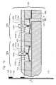
- Fig. 1a Schematic representations of an inventive device for intermittent coating with variable internal volume during the coating phase.
- Fig. 1a is a section through an inventive device for intermittent coating 100 with variable internal volume shown.
- a nozzle slot 103 is adjusted by means of a liner 108 with a recess (not shown).
- the insert film 108 extends over the entire length and width of the nozzle jaws 101,102 and is preferably in metal with a thickness of between 0.01 mm and 3.00 mm, preferably between 0.05 mm and 1.0 mm, more preferably between 0.3 mm and 0.5 mm.
- the recess (not shown) forms a cavity during assembly, which extends from the inlet channel 107 to the outlet gap 130.
- the exit slit 130 of the device is in this case positioned transversely to the transport direction U of the substrate 170 and parallel to the substrate 170.
- an opening 123 is provided in the nozzle jaw 101, an adjustment unit 120a being integrated in the opening 123.
- the arrangement comprises a flexible element 121a, wherein flexibly defined here in the sense of yielding or flexible, belonging to a sealing element 122a, an actuator 124a, an associated flat attachment 125a and a cover 126a.
- the elastically deformable element 121a is fixed and sealed at the edge regions in the opening 123a by a sealing element 122a and the cover 126a in their position on a lug in the nozzle jaw 101.
- the elastically deformable element 121a By the elastically deformable element 121a, the nozzle slot 103, in its height and thus the total volume of the nozzle slot 103 can be varied.
- a suitable sensor (not shown) is integrated in the cover 126a.
- an actuator 124a is provided in the central region of the flexible element 121a.
- the actuator 124a is in contact with the flexible member 121a through an attachment 125a, and thereby can control the deformation of the flexible member 121a.
- the flexible element 121a which is acted upon by the nozzle slot from the pressure of the feed pump is held by the counterforce or increasing counterforce of the actuator 124a (second switching position) in its position or shape, ie the actuator pushes the flexible element 121a in the direction of the nozzle slot 130, but in this case the nozzle slot 130 is not narrowed.
- a further adjustment unit 120b is additionally integrated in the same nozzle jaw 103, whereby it is positioned between the adjustment unit 120b and the inlet channel 107.
- the volume in the nozzle slot 103 is also variable, with the adjustment unit 120b no volume increase of the nozzle slot 103 is intended.
- the pressure runs continuously within the nozzle body 100 or the nozzle slot 103, starting from the inlet channel 107 to the outlet gap 130.
- the shear stress ⁇ is above the entire nozzle slot 103 above the yield point ⁇ f .
- Fig. 1b Schematic representation of the geometric relationships at the exit slit
- Fig. 1b is a schematic representation of the geometric relationships at the exit slit 130 reproduced.
- the nozzle slot 103 ends transversely to the transport direction U of the substrate 170 and parallel to the substrate 170 as an exit slit 130 of the nozzle body 100 cf. Fig. 1a wherein the exit slit 130 via the nozzle slot 103 in flow communication with the inlet channel 107 cf. Fig. 1a is.
- the width of the exit gap 165 here corresponds to the thickness of the insert film 108 and defines the distance between the upstream nozzle lip 131 and the downstream nozzle lip 132.
- a liquid bridge 160 from.
- the thickness of the liquid bridge 165 is higher than the desired wet film thickness 164.
- Fig. 1c Schematic representations of a device according to the invention for intermittent coating with variable internal volume, during the interruption phase.
- Fig. 1c the device according to the invention is shown schematically during the beginning of the interruption phase.
- the flexible member 121a is deformed only by the action of the system pressure p such that it results in an increase in the volume in that portion of the nozzle slot 103.
- the change with time of the increase in the volume in this section is adjusted so that the further inflowing coating material is taken up in the variable volume of the nozzle slot 103.
- the pressure within the nozzle slot 103 in the direction of the exit slit 130 at the same time thereby immediately drops approximately to ambient pressure. This leads to the tearing off of the liquid bridge 160 cf. Fig. 1b , at the nozzle slot 103.
- shear stress ⁇ in the direction of the exit slit 130, below the yield point ⁇ f .
- shear stress ⁇ in its direction to exit gap 130 remains unchanged and is greater than 0.
- activation of the actuator 124b deforms the flexible element 121b such that this results in a reduction of the nozzle slot 103.
- a constriction in the nozzle slot 103 is generated, which brings a local pressure increase with it.
- the shearing stress ⁇ in the coating material is increased and the flow rate in this section increases.
- local pressure fluctuations are generated which directly affect local flow rates to optimally control the coating process.
- Fig. 1d Schematic representations of an inventive device for intermittent coating with variable internal volume, during the end of the interruption phase or start of the coating phase.
- the adjustment gap 120a reduces the outlet gap 130 or the variable internal volume in the region of the flexible element 121a.
- a slight change in volume and the resulting increased pressure in the coating material is sufficient to overcome the yield strength ⁇ f of the coating material.
- the applied shear stress ⁇ in the coating material in the nozzle slot 103 between the exit slit 130 and the area around the flexible element 124a reduces the necessary initial pulse.
- the variable internal volume is now distributed continuously over the entire coating phase or the flexible element 121 is deformed in such a way that the nozzle slot 103 is reduced in size but not smaller than the gap width 133 set by the insert film 108.
- the coating material already present in the variable internal volume is supplied to the delivery volume flow q.
- the speed of the coating material supplied is adjusted to the substrate speed. The adaptation takes place accordingly by the movement speed or by the time profile of the opposite force by the actuator 124a.
- Fig. 2a Schematic representations of a device according to the invention for intermittent coating with variable internal volume with double gap
- Fig. 2a are the jaws 101,102 of the device 200 together with the adjustment unit 120a and 120b, and 120c and 120d arranged around a preferably wedge-shaped partition plate 104, mirrored.
- Fig. 2b Schematic representation of the geometric relationships at the exit slit of a device according to the invention with double slit
- Fig. 2b is a schematic representation of the geometric relationships at the exit slit 130 reproduced.
- the nozzle slots 103 end in each case transversely to the transport direction U of the substrate 170 and parallel to the substrate 170 as an exit slit 130 of the nozzle body 200 cf.
- Fig. 2b wherein the respective exit slit 130 via the respective nozzle slot 103 in flow communication with the respective inflow passage 107 cf.
- Fig. 2 is.
- the width of the respective exit gap 133 here corresponds to the thickness of the insert film 108 and defines the distance between the upstream nozzle lip 131 and the downstream nozzle lip 132. In between, the partition plate 104 is arranged.
- a liquid bridge 160 is formed during the coating process.
- the liquid bridge 160 differs here from the in Fig. 1b , in such that the thickness of the liquid bridge 160 results from two partial streams q a and q b .
- the wet film thickness 164 results from the wet film thickness of the coating material A 166 and the wet film thickness of the coating material B 167.
Landscapes
- Chemical & Material Sciences (AREA)
- Engineering & Computer Science (AREA)
- Chemical Kinetics & Catalysis (AREA)
- Electrochemistry (AREA)
- General Chemical & Material Sciences (AREA)
- Manufacturing & Machinery (AREA)
- Materials Engineering (AREA)
- Coating Apparatus (AREA)
- Application Of Or Painting With Fluid Materials (AREA)
Description
- Die Erfindung betrifft ein Verfahren und eine Vorrichtung zum intermittierenden Beschichten eines bewegten Substrats.
- Aus der japanischen Patentoffenlegungsschrift
JP 2001 191 005 A - Alternativ wird ein intermittierendes Beschichten dadurch erreicht indem der Beschichtungsspalt zwischen der Düse und dem Substrat mit jeder Beschichtungsunterbrechung zu vergrößern. Der dennoch vorhandene Nachlauf des Beschichtungsstoffs benetzt allerdings die Düsenlippen was bei einer erneuten Annäherung an das Substrat (Ableiterfolie) zu einer Überhöhung der Startkante führt.
Nachteilig an diesem Ansatz ist auch, dass durch die Bewegung der Düse und das Aufsetzten der benetzten Düsenlippen auf das Substrat, Vibrationen in dem Substrat verursacht werden, welche wiederum den Abstand der Düsenlippen zum Substrat beeinflussen. Demensprechend ist es nicht möglich, eine kontinuierliche Nassfilmdicke zu realisieren. - Sekundäre Lithium-Ionen Batterien basieren auf einer Anordnung von mehreren elektrochemischen Zellen. Die Elektroden in einer elektrochemischen Zelle weisen jeweils ein Aktivmaterial auf, aus dem während des Betriebs der elektrochemischen Zelle Lithium-Ionen in die Elektroden interkaliert werden. In der negativen Elektrode (Kathode) werden als Aktivmaterial lithiumhaltiges Verbundoxid, bevorzugt LiCoO2, LiFePO4, LiNi1/3Co1/3Mn1/3O2 (NCM) oder LiNi0,8Co0,15Al0,05O2 (NCA), mesoporöses Titanoxid, und in der positiven Elektrode (Anode) Leitruß, Ruß, Graphit o.ä. eingesetzt.
- Aus der
DE 10 2004 012 476 A1 sind geeignete Beschichtungsstoffe und deren Herstellung bekannt und werden hiermit durch das Referenzieren mit in die Anmeldung einbezogen.
Bei einem hier vorgeschlagenen Beschichtungsverfahren wird der für die Kathoden- bzw. Anodenbeschichtungsmasse (Beschichtungsstoff) erforderliche Polymerbinder gelöst z.B. in 5-10%ige Fluorelastomer-Homo- oder Copolymerisate in N-Methyl-pyrrolidon (NMP) und die dabei entstehende Polymerlösung mit den kathoden- bzw. anodenspezifischen Zusätzen wie Lithium interkalierbare Metalloxide bzw. Lithium interkalierbare Kohlenstoffe (Leitruß, Ruß, Graphit o.ä.) versetzt und dispergiert. Dann wird diese Dispersion mit einer Filmbeschichtungstechnik auf das Substrat hier die Stromkollektoren bzw. ein Sammelkörper wie Folien, Bändern, Netzen o.ä. aufgetragen. - Alternativ kann auch Polyvinyliden-Fluorid als Binder auf der Kathodenseite und Styrol-Butadien-Kautschuk auf der Anodenseite,zur Verbesserung der mechanischen Festigkeit eingesetzt werden und mit Leitruß (Leitfähigkeitsruß), zur Erhöhung der elektrischen Leitfähigkeit versehen werden. Die Aktivmaterialien werden dementsprechend in Form von Pasten (Beschichtungsstoff) unter Einsatz von Lösungsmitteln sowie Carboxymethylcellulose als Verdicker auf das Substrat bzw. das metallische Ableitermaterial aufgebracht.
- Aufgrund der geringen elektrischen Leitfähigkeit der porösen, partikulären Schichtmorphologien, weist die aufgetragene Elektrodenschicht (Nassfilm) mangelhafte Entladungsrateneigenschaften auf. Um die Elektrizitätssammelfähigkeit zu erhöhen, muss daher die aufgetragene Elektrodenschicht, welche auf dem elektrisch leitenden Substrat (Sammelkörper, Elektrode) aufgetragen wird, so dünn wie möglich ausgeführt sein. Vorzugsweise werden hier Nassfilmdicken der Menisken zwischen 10 µm (hohe Leistung) und 850 µm (hohe Kapazitäten) angestrebt.
- M. Schmitt et al., "Slot-die processing of lithium-ion battery electrodes-Coating window characterization", Chemical Engineering and Processing: Process Intensification, Volume 68, June 2013, Pages 32-37 sowie M. Schmitt et al. "Slot die coating of lithium-ion battery electrodes: investigations on edge effect issues for stripe and pattern coatings", Journal of Coatings Technology and Research January 2014, Volume 11, Issue 1, pp 57-63 lehren ein geeignetes Verfahren zum Beschichten von Folienelektroden mit einer Schlitzdüse sowie die optimalen Betriebsbedingungen zur Durchführung dieses Verfahrens betreffend der geometrischen Abmaße einer geeigneten Vorrichtung und werden hiermit durch das Referenzieren mit in die Anmeldung einbezogen.
- Um exakte (Film-)Start-und (Film-)Stopkanten der Schichten bzw. der Beschichtungsabschnitte zu erhalten, ist bereits aus der
DE 10 246 327 A1 bekannt, den Beschichtungsstoff, nach dem Absperren (Verschließen) des Zulaufkanals, zurückzuziehen, dieser Effekt ist als der sogenannte "Snuff-Back" bekannt. Der Beschichtungsstoff wird nach dem Sperrmittel und vor dem Austritt, einen Unterdruck entgegengesetzt der ursprünglichen Flussrichtung gestoppt und zurück bewegt. - Eine Alternative hierzu offenbart die
US 2002/0017238 A1 in dieser ist eine Vorrichtung offenbart, welche eine intermittierende Beschichtung auf ein bewegtes Substrat aufträgt, wobei die Beschichtungsunterbrechung nicht durch Verschließen durch eine Sperrmittel in Verbindung mit einem Snuff-Back vor dem Austritt hervorgerufen wird, sondern durch eine Kombination aus Änderung des Innvolumens der Schlitzdüse in Verbindung mit einem Snuff-Back-Effekt. Dies wird durch das aktive Hin- und Herbewegen des flexiblen Elements durch eine Verstelleinheit in einem Düsenbacken hervorgerufen. Die aktive Volumenvergrößerung bewirkt eine Sogwirkung wodurch der Snuff-Back auf den Beschichtungsstoff in dem Austrittsspalt wirkt. Dementsprechend wird die Flussrichtung und die in dem Beschichtungsstoff anliegende Scherspannung τ in ihrer Richtung umgekehrt. Der Beschichtungsstoff wird hier vor dem Auftragen auf dem Substrat, zeitweise in der mit Unterdruck beaufschlagten Kavität oder in dem flexiblen Volumen gespeichert. Der gespeicherte Beschichtungsstoff wird dann während eines darauf folgenden Beschichtungszyklus aufgetragen. - Es hat sich aber gezeigt, dass hierdurch unerwünschte Druckschwankungen bzw. Druckspitzen in dem System auftreten, welche gerade beim Starten des Beschichtungsvorgangs zu Störungen führt. Durch das schlagartige Öffnen des Sperrmittels (Ventil) treten Druckspitzen auf. Auch durch- das verkleinern des flexiblen Innenvolumens, wobei der in der Kavität gespeicherten Beschichtungsstoff dem Fördervolumenstrom wieder zugeführt wird, bildet sich eine undefinierte Anlaufströmung in dem Düsenschlitz aus. Ursache hierfür ist, dass die Scherspannung τ des Fördervolumenstroms eine andere Richtung als die des durch den Snuff-Back zurückgehaltenen Teilvolumenstroms hat.
Somit muss erst eine Richtungsänderung der Scherspannung des zurückgehaltenen Teilvolumenstroms,erzwungen werden um eine genügend hohe stationäre Scherung bzw. Scherspannung τ in Richtung des Düsenaustritts zu erhalten. Dementsprechend ist die Anlaufströmung zu gering ausgeprägt, und es bilden sich unerwünschten Quer- bzw. Längsstreifen auf den erzeugten Beschichtungen. - Des Weiteren sind die Fließ- und Verarbeitungseigenschaften des Beschichtungsstoffs zur Herstellung von Elektrodenschichten für Li-Ionen-Zellen entscheidend für Auslegung der Vorrichtung und des Verfahrens. Hier werden Schergeschwindigkeiten γ̇ (Scherraten) des Beschichtungsstoffs von bis zu 100. 000 s-1 erreicht. Die Schergeschwindigkeit wird berechnet aus dem Verhältnis zwischen dem Geschwindigkeitsunterschied zweier benachbarter. Flüssigkeitsschichten und deren Abstand. Mathematisch ausgedrückt ist die Schergeschwindigkeit der Gradient des Geschwindigkeitsfeldes.
Dies ist gerade für die hier zum einsatzkommenden Beschichtungsstoffe entscheidend, da diese sich strukturviskos bzw. scherverdünnend verhalten. Somit setzt ein Volumenstrom erst bei der Einwirkung einer Schubspannung τ oberhalb einer minimalen Schubspannung τf (Fließgrenze) ein. - Ein weiterer Nachteil, der aus dem Stand der Technik bekannten Vorrichtungen ist, dass diese nur intermittierend sequentielle Beschichtungen auftragen. Ein zeitgleiches Auftragen mehrerer Schichten aufeinander ist nicht vorgesehen.
- Ausgehend hiervon liegt die Aufgabe der Erfindung darin, eine Vorrichtung und ein Verfahren vorzuschlagen, welche eine intermittierende Beschichtung eines bewegten Substrats bei einer konstanten Nassfilmdicke unter Einhaltung exakter Filmkanten gewährleistet und somit die Nachteile und Einschränkungen, welche aus dem Stand der Technik bekannt sind, vermeidet.
- Gelöst wird die Aufgabe im Hinblick auf die Erzeugung von exakten Filmstartkanten und Filmstoppkanten durch eine Vorrichtung zum intermittierenden Beschichten eines in Bewegung befindlichen Substrats mit den Merkmalen nach Anspruch 1 und im Hinblick auf das Verfahren durch die Verfahrensschritte gemäß der jeweiligen Ansprüche 5, 6 und 7. Weiterbildungen bzw. bevorzugte Ausführungsformen der Vorrichtung bzw. des Verfahrens sind in den Unteransprüchen ausgeführt.
- Zur Lösung der Aufgabe wird eine Vorrichtung vorgeschlagen, welche einen Düsenkörper mit mindestens zwei Düsenbacken umfasst. Zwischen den gegenüberliegenden Düsenbacken ist eine Einlagefolie mit mindestens einer Aussparung vorgesehen. Die Aussparung in der Einlagefolie bildet mindestens einen Düsenschlitz innerhalb des Düsenkörpers aus. Der Düsenschlitz endet quer zur Transportrichtung U des Substrats relativ zum Düsenkörper und parallel zum Substrat als Austrittsspalt des Düsenkörpers, wobei der Austrittsspalt über den Düsenschlitz in Strömungsverbindung mit dem Zulaufkanal ist. Wenigstens eine Düsenbacke ist mit mindestens zwei Durchbrüchen versehen, welche in den Düsenschlitz ausmünden und jeweils mit einem elastischen verformbaren Element in Verbindung mit einer Abdeckung und einem Dichtelement zum Düsenschlitz und zur unter Ausbildung eines Volumens hin verschlossen sind. Jedes elastisch verformbare Element ist einerseits mit dem Beschichtungsstoff im Düsenschlitz und andererseits mit einem Aktor verbunden. Die mindestens zwei Durchbrüche ausmünden seriell in den Düsenschlitz.
- Die Durchbrüche eines Düsenbackens sind aufeinanderfolgend in Flussrichtung q des Beschichtungsstoffs, ausgehend vom Zulaufkanal zum Austrittsspalts angeordnet sind. Die elastischen verformbaren Elemente sind durch die Aktoren wechselseitig zwischen jeweils zwei Schaltstellungen unter Veränderung des jeweiligen Volumens be- und entlastbar.
- Nach Anspruch 5 besteht das Verfahren zum intermittierenden Beschichten von einem bewegenden Substrat aus folgenden Verfahrenschritten, wobei der Fördervolumenstrom q des Beschichtungsstoffs über alle Verfahrensschritte konstant bleibt:
Der Beschichtungsstoff wird mittels einer Pumpe ausgehend vom Zuführkanal über den Düsenschlitz mit konstantem Fördervolumenstrom q zum Austrittsspalt gefördert.
Durch das Entlasten (erste Schaltstellung) des flexiblen Elements, welches dem Austrittsspalt am nächsten liegt, herbeigeführt durch die Reduzierung der Kraft oder auch Gegenkraft des zugehörigen Aktors und durch zeitgleiches Belasten (zweite Schaltstellung) des flexiblen Elements, welches dem Zuführkanal am nächsten liegt, herbeigeführt durch Anhebung der Gegenkraft des zugehörigen Aktors, wird das Auftragen des Beschichtungsstoffs auf das Substrat unterbrochen. Das Be- und Entlasten des bzw. der Aktoren wird hierbei als Schaltzustand bezeichnet, wobei in jedem Schaltzustand sich die Richtung der durch den Aktor ausgeübten Kraft auf das flexible Element nicht ändert sondern nur der Betrag der ausgeübten Kraft.
Durch das Belasten des flexiblen Elements, welches dem Austrittsspalt am nächsten liegt, herbeigeführt durch die Anhebung der Gegenkraft des zugehörigen Aktors und das zeitgleiche Entlasten des flexiblen Elements, welches dem Zuführkanal am nächsten liegt, herbeigeführt durch die Reduzierung der Gegenkraft des zugehörigen Aktors, wird das Auftragen des Beschichtungsstoffs auf das Substrat wieder hergestellt. - Nach Anspruch 6 besteht das Verfahren zum intermittierenden Beschichten von einem in Bewegung befindlichen Substrat aus folgenden Verfahrenschritten, wobei der Fördervolumenstrom der Beschichtungsstoffe oder des Beschichtungsstoffs qa und qb über alle Verfahrensschritte konstant bleiben und sich die Beschichtungsabschnitte überlagern:
Der Beschichtungsstoff oder die Beschichtungsstoffe A,B wird bzw. werden mittels einer' oder zwei Pumpen ausgehend vom zugehörigen Zuführkanal über den jeweiligen Düsenschlitz zum korrespondierenden Austrittsspalt gefördert.
Durch das zeitgleiche Entlasten (erste Schaltstellung) der flexiblen Elemente, welche dem jeweiligen Austrittsspalt am nächsten liegen, herbeigeführt durch das Reduzieren der Gegenkraft des zugehörigen Aktors, und durch zeitgleiches Belasten der flexiblen Elemente, welche dem jeweiligen Zuführkanal am nächsten liegen, herbeigeführt durch die Erhöhung der Gegenkraft (zweite Schaltstellung) des zugehörigen Aktors, wird das Auftragen der Beschichtungsstoffe A,B oder des Beschichtungsstoffs auf das Substrat unterbrochen.
Durch das zeitgleiche Belasten der flexiblen Elemente, welche dem jeweiligen Austrittsspalt am nächsten liegen, herbeigeführt durch die Erhöhung der Gegenkraft (zweite Schaltstellung) des zugehörigen Aktors und das zeitgleiche Entlasten der flexiblen Elemente, welche dem jeweiligen Zuführkanal am nächsten liegen, herbeigeführt durch die Reduzierung der Gegenkraft (zweite Schaltstellung) des zugehörigen Aktors, wird das Auftragen der Beschichtungsstoffe oder des Beschichtungsstoffs auf das Substrat wieder hergestellt. - Nach Anspruch 7 besteht das Verfahren zum intermittierenden Beschichten von einem in Bewegung befindlichen Substrat aus folgenden Verfahrenschritten, wobei der Fördervolumenstrom qa und qb der Beschichtungsstoffe über alle Verfahrensschritte konstant bleiben und sich die Beschichtungsabschnitte nicht überlagern:
Die oder der Beschichtungsstoff wird mittels einer Pumpe ausgehend vom zugehörigen Zuführkanal über den jeweiligen Düsenschlitz zum korrespondierenden Austrittsspalt gefördert.
Durch das Entlasten des flexiblen Elements in einem Düsenbacken welches dem Austrittsspalt am nächsten liegt, herbeigeführt durch die Reduzierung der Gegenkraft (erste Schaltstellung) des zugehörigen Aktors, und durch zeitgleiches Belasten des flexiblen Elements, welche dem Zuführkanal am nächsten liegt, herbeigeführt durch die Erhöhung der Gegenkraft (zweite Schaltstellung) des zugehörigen Aktors, wird das Auftragen des Beschichtungsstoffs durch diesen Düsenspalt auf das Substrat unterbrochen. - Zeitgleich wird in dem gegenüberliegenden Düsenbacken durch das Belasten des flexiblen Elements, welches dem Austrittsspalt am nächsten liegt, herbeigeführt durch die die Erhöhung der Gegenkraft (zweite Schaltstellung) des zugehörigen Aktors und das zeitgleiche Entlasten des flexiblen Elements, welches dem Zuführkanal am nächsten liegt, herbeigeführt durch die Reduzierung der Gegenkraft (erste Schaltstellung) des zugehörigen Aktors, das Auftragen des Beschichtungsstoffs auf das Substrat ausgeführt.
Anschließend wird das Verfahren in umgekehrter Reihenfolge wiederholt. - Die Erfindung wird im Folgenden anhand von Ausführungsbeispielen und den Figuren näher erläutert. Hierbei zeigen:
-
Fig. 1a : Schematische Darstellungen einer erfindungsgemäßen Vorrichtung zum intermittierenden Beschichten mit variablem Innenvolumen während der Beschichtungsphase. -
Fig. 1b : Schematische Darstellung der geometrischen Verhältnisse am Austrittspalt -
Fig. 1c : Schematische Darstellungen einer erfindungsgemäßen Vorrichtung zum intermittierenden Beschichten mit variablemInnenvolumen, während des Beginns der Unterbrechungsphase. -
Fig. 1d : Schematische Darstellungen einer erfindungsgemäßen Vorrichtung zum intermittierenden Beschichten mit variablem Innenvolumen, während dem Ende der Uriterbrechungsphase bzw. Start der Beschichtungsphase. -
Fig. 2a : Schematische Darstellungen' einer erfindungsgemäßen Vorrichtung zum intermittierenden Beschichten mit variablem Innenvolumen mit Doppelspalt -
Fig. 2b : Schematische Darstellung der geometrischen Verhältnisse am Austrittspalt
einer erfindungsgemäßen Vorrichtung mit Doppelspalt - Es folgt die Erläuterung der Erfindung anhand der Zeichnungen nach Aufbau und ggf. auch nach Wirkungsweise der dargestellten Erfindung.
- In
Fig. 1a ist ein Schnitt durch eine erfindungsgemäße Vorrichtung zum intermittierenden Beschichten 100 mit variablem Innenvolumen dargestellt. Zwischen zwei Düsenbacken 101, 102 wird ein Düsenschlitz 103 mittels einer Einlagefolie 108 mit einer Aussparung (nicht dargestellt) eingestellt. Die Einlagefolie 108 erstreckt sich über die gesamte Länge und Breite der Düsenbacken 101,102 und ist vorzugsweise in Metall mit einer Dicke zwischen 0,01 mm und 3,00 mm, vorzugsweise zwischen 0,05 mm und 1,0 mm, besonders bevorzugt zwischen 0,3 mm und 0,5 mm ausgeführt. Die Aussparung (nicht dargestellt) bildet im Zusammenbau eine Kavität aus, welche sich von dem Zulaufkanal 107 bis zum Austrittsspalt 130 erstreckt. Der Austrittsspalt 130 der Vorrichtung ist hierbei quer zur Transportrichtung U des Substrats 170 und parallel zum Substrat 170 positioniert. - Vor dem Düsenaustritt 130 ist in der Düsenbacke 101 ein Durchbruch 123 vorgesehen, wobei in dem Durchbruch 123 eine Verstelleinheit 120a integriert ist. Die Anordnung umfasst ein flexibles Element 121a, wobei flexibel hier im Sinne von nachgiebig bzw. biegsam definiert wird, zugehörig ist ein Dichtelement 122a, eine Aktor 124a, ein zugehöriger flächiger Aufsatz 125a und eine Abdeckung 126a. Das elastisch verformbare Element 121a wird hierzu an den Randbereichen im Durchbruch 123a von einem Dichtelement 122a und der Abdeckung 126a in ihrer Position auf einer Nase im Düsenbacken 101 fixiert und abgedichtet. Durch das elastisch verformbare Element 121a kann der Düsenschlitz 103, in seiner Höhe und somit das Gesamtvolumen des Düsenschlitzes 103 variiert werden. Zur Überwachung der Verformung des flexiblen Elements 121a und somit des variablen Volumens im Düsenschlitz 103, ist eine geeignete Sensorik (nicht dargestellt) in der Abdeckung 126a integriert.
- Im zentralen Bereich des flexiblen Elements 121a ist ein Aktor 124a vorgesehen. Der Aktor 124a ist mit dem flexiblen Element 121a durch einen Aufsatz 125a in Kontakt, und kann hierdurch die Verformung des flexiblen Elements 121a steuern. Das flexible Element 121a, welches vom Düsenschlitz her mit dem Druck der Förderpumpe beaufschlagt ist, wird durch die Gegenkraft bzw. steigende Gegenkraft des Aktors 124a (zweite Schaltstellung) in seiner Position bzw. Form gehalten, d.h. der Aktor drückt das flexible Element 121a in Richtung des Düsenschlitzes 130, jedoch wird hierbei der Düsenschlitz 130 nicht verengt.
- Ebenfalls im selben Düsenbacken 103 ist zusätzlich eine weitere Verstelleinheit 120b integriert, wobei diese zwischen der Verstelleinheit 120b und dem Zulaufkanal 107 positioniert ist. Hierdurch ist das Volumen im Düsenschlitz 103 ebenfalls variierbar, wobei mit der Verstelleinheit 120b keine Volumenvergrößerung des Düsenschlitzes 103 beabsichtigt ist. Der Druck verläuft innerhalb des Düsenkörpers 100 bzw. dem Düsenschlitz 103 beginnend vom Zulaufkanal 107 bis zum Austrittsspalt 130 stetig fallend. Die Scherspannung τ liegt über den gesamten Düsenschlitz 103 oberhalb der Fließgrenze τf.
- in
Fig. 1b ist eine schematische Darstellung der geometrischen Verhältnisse am Austrittspalt 130 wiedergegeben. Der Düsenschlitz 103 endet quer zur Transportrichtung U des Substrats 170 und parallel zum Substrat 170 als Austrittsspalt 130 des Düsenkörpers 100 vgl.Fig. 1a , wobei der Austrittsspalt 130 über den Düsenschlitz 103 in Strömungsverbindung mit dem Zulaufkanal 107 vgl.Fig. 1a ist. Die Breite des Austrittspalts 165 entspricht hier der Dicke der Einlagefolie 108 und definiert den Abstand zwischen der Stromaufwärts gelegenen Düsenlippe 131 und der Stromabwärts gelegenen Düsenlippe 132. Zwischen dem Austrittsspalt 130 bzw. den beiden Düsenlippen (131,132) und dem in Bewegung befindlichen Substrat 170 bildet sich während des Beschichtungsprozesses eine Flüssigkeitsbrücke 160 aus. Die Dicke der Flüssigkeitsbrücke 165 ist höher als die gewünschte Nassfilmdicke 164. - In
Fig. 1c ist die erfindungsgemäße Vorrichtung schematische während des Beginns der Unterbrechungsphase dargestellt. Hier wird durch das Deaktivieren des Aktors 124a, das flexible Element 121a, nur durch die Wirkung des Systemdrucks p derart verformt, dass dies eine Vergrößerung des Volumens in diesem Abschnitt des Düsenschlitzes 103 zur Folge hat. Die zeitliche Änderung der Vergrößerung des Volumens in diesem Abschnitt wird so eingestellt, dass der weiterhin anströmende Beschichtungsstoff in das variable Volumen des Düsenschlitzes 103 aufgenommen wird. Der Druck innerhalb des Düsenschlitzes 103 in Richtung des Austrittsspalts 130 fällt zeitgleich hierdurch sofort annähernd auf Umgebungsdruck ab. Hierdurch kommt es zum Abreißen der Flüssigkeitsbrücke 160 vgl.Fig. 1b . am Düsenschlitz 103. Dementsprechend liegt die Scherspannung τ, in Richtung des Austrittsspalts 130, unterhalb der Fließgrenze τf. Jedoch bleibt Scherspannung τ in ihrer Richtung zu Austrittsspalts 130 unverändert und ist grösser > 0. Zeitgleich wird durch Aktivierung des Aktors 124b das flexible Element 121b derart verformt, dass dies eine Verringerung des Düsenschlitzes 103 zur Folge hat. Hierdurch wird eine Verengung im Düsenschlitz 103 erzeugt, welche eine lokale Druckerhöhung mit sich bringt. Hierbei wird die Scherspannung τ im Beschichtungsstoff gesteigert und die Flussgeschwindigkeit in diesem nimmt Abschnitt, zu. Somit werden lokale Druckschwankungen erzeugt welche sich direkt in lokale Fließgeschwindigkeiten auswirken um den Beschichtungsvorgang optimal zu regeln. - Zu Beginn der darauffolgenden Beschichtungsphase wird durch die Verstelleinheit 120a der Austrittsspalt 130 bzw. das variable Innenvolumen im Bereich des flexiblen Elements 121a verkleinert.
- Eine geringfügige Volumenänderung und der daraus erhöhte resultierenden Druck im Beschichtungsstoff reicht aus um die Fließgrenze τf des Beschichtungsstoffs zu überwinden. Die noch anliegende Scherspannung τ im Beschichtungsstoff in dem Düsenschlitz 103 zwischen dem Austrittspalt 130 und dem Bereich um das flexible Element 124a reduziert den notwendigen Anfangsimpuls. Das variable Innenvolumen wird nun über die gesamte Beschichtungsphase verteilt kontinuierlich verkleinert bzw. das flexible Element 121 wird derart verformt das sich der Düsenschlitzes 103 in verkleinert, jedoch nicht kleiner wird als die durch die Einlagefolie 108 eingestellte Spaltbreite 133.
- Hierbei wird der bereits in dem variablen Innenvolumen vorhanden Beschichtungsstoff dem Fördervolumenstrom q zugeführt. Für eine definierte Nassfilmdicke 164 wird die Geschwindigkeit des zugeführten Beschichtungsstoffs an die Substratgeschwindigkeit angepasst. Die Anpassung erfolgt dementsprechend durch die Bewegungsgeschwindigkeit bzw. durch den zeitlichen Verlauf der entgegengesetzten Kraft durch den Aktors 124a.
- Gemäß
Fig. 2a sind die Düsenbacken 101,102 der Vorrichtung 200 zusammen mit der Verstelleinheit 120a und 120b, sowie 120c und 120d um eine vorzugsweise keilförmige Trennplatte 104, gespiegelt angeordnet. - Dementsprechend ergibt sich mit einer zusätzlichen Einlagefolie 108 zwischen der Trennplatte 104 und dem Düsenbacken 102 ein weiterer Düsenschlitz 103.
- Hierdurch ist zum einen möglich,eine simultane Beschichtung von zwei unterschiedlichen Beschichtungsstoffen und zum anderen eine Beschichtung mit demselben Beschichtungsstoff in der doppelten Geschwindigkeit durchzuführen. Zudem kann eine Beschichtung in zwei Lagen vorgenommen werden.
- In
Fig. 2b ist eine schematische Darstellung der geometrischen Verhältnisse am Austrittspalt 130 wiedergegeben. Die Düsenschlitze 103 enden jeweils quer zur Transportrichtung U des Substrats 170 und parallel zum Substrat 170 als Austrittsspalt 130 des Düsenkörpers 200 vgl.Fig. 2b , wobei der jeweilige Austrittsspalt 130 über den jeweiligen Düsenschlitz 103 in Strömungsverbindung mit dem jeweiligen Zulaufkanal 107 vgl.Fig. 2 ist. - Die Breite des jeweiligen Austrittspalts 133 entspricht hier der Dicke der Einlagefolie 108 und definiert den Abstand zwischen der Stromaufwärts gelegenen Düsenlippe 131 und der Stromabwärts gelegenen Düsenlippe 132. Dazwischen ist die Trennplatte 104 angeordnet.
- Somit ergibt sich ein weiterer Austrittspalt 133 der einem unterschiedlichen Beschichtungsstoff beschickt wird. Zwischen dem jeweiligen Austrittsspalt 130 bzw. den beiden Düsenlippen 131, 132 und dem in Bewegung befindlichen Substrat 170 bildet sich während des Beschichtungsprozesses eine Flüssigkeitsbrücke 160 aus. Die Flüssigkeitsbrücke 160 unterscheidet sich hier allerdings von der in
Fig. 1b , in derart das die Dicke der Flüssigkeitsbrücke 160 sich aus beiden Teilströmen qa und qb ergibt. Dementsprechend resultiert die Nassfilmdicke 164 aus der Nassfilmdicke des Beschichtungsstoffs A 166 und der Nassfilmdicke des Beschichtungsstoffs B 167 sich. -
- 100, 200
- Vorrichtung zum intermittierenden Beschichten
- 101
- Düsenbacken
- 102
- Düsenbacken
- 103
- Düsenschlitz
- 104
- Trennplatte
- 105
- Düsenbackenausfräsung
- 107
- Zulaufkanal
- 108
- Einlagefolie
- 120
- Verstelleinheit
- 121
- Flexibles Element
- 122
- Dichtelement
- 123
- Durchbruch
- 124
- Aktor Punkt- oder linienförmiger oder flächiger Aufsatz
- 125
- des Aktors
- 126
- Abdeckung.
- 130
- Austrittsspalt
- 131
- Stromaufwärts gelegene Düsenlippe
- 132
- Stromabwärts gelegene Düsenlippe
- 133
- Breite Austrittspalt
- 160
- Flüssigkeitsbrücke
- 161
- Nassfilm, Flüssigkeitsfilm auf dem Substrat
- 162
- Stoppkante, Filmstoppkante
- 163
- Startkante, Filmstartkante
- 164
- Nassfilmdicke
- 165
- Dicke der Flüssigkeitsbrücke 160
- 166
- Nassfilmdicke des Beschichtungsstoffs A
- 167
- Nassfilmdicke des Beschichtungsstoffs B
- 170
- Substrat
- U
- Bewegungsrichtung des Substrat
- q, qa, qb
- Fördervolumenstrom
- p
- Druck
Claims (7)
- Vorrichtung zum intermittierenden Beschichten eines relativ zur Vorrichtung in einer Transportrichtung U in Bewegung befindlichen Substrats, umfassend
einen Düsenkörper (100) mit mindestens zwei Düsenbacken (101, 102), wobei zwischen den Düsenbacken (101, 102) eine Einlagefolie (108) mit einer Aussparung vorgesehen ist, wobei die Aussparung in der Einlagefolie (108) einen Düsenschlitz (103) innerhalb des Düsenkörpers (100) bildet, und der Düsenschlitz (103) quer zur Transportrichtung U des Substrats (170) und parallel zum Substrat (170) erstreckend in einem Austrittsspalts (130) endet, wobei der Austrittsspalt (130) über den Düsenschlitz (103) in Strömungsverbindung mit einem Zulaufkanal (107) ist und wenigstens eine Düsenbacke (101, 102) mit mindestens zwei Durchbrüchen (123a, 123b) versehen ist, welche zwischen dem Zulaufkanal und dem Austrittsspalt (130) in den Düsenschlitz (103) ausmünden und jeweils mit einem elastischen verformbaren Element (121a, 121b) fluiddichtend zum Düsenschlitz (103) unter Ausbildung eines Volumens hin verschlossen sind, wobei
jedes elastisch verformbare Element (121a, 121b) einerseits mit dem Beschichtungsstoff im Düsenschlitz (103) und andererseits mit einem Aktor (124a, 124b) in Richtung des Düsenschlitzes (103) wirkend verbunden ist,
dadurch gekennzeichnet, dass
die mindestens zwei Durchbrüche seriell in den Düsenschlitz ausmünden, wobei die Durchbrüche (123a, 123b) eines Düsenbackens (101, 102) aufeinanderfolgend in Flussrichtung q des Beschichtungsstoffs ausgehend vom Zulaufkanal (107) zum Austrittsspalts (130) hin angeordnet sind,
die elastischen verformbaren Elemente (121a, 121b) durch die Aktoren (124a, 124b) gleichzeitig wechselseitig zwischen jeweils zwei Schaltstellungen unter Veränderung des jeweiligen Volumens be- und entlastbar sind. - Vorrichtung nach Anspruch 1,
dadurch gekennzeichnet, dass
zwischen den Düsenbacken (101,102) eine Trennplatte (104) angeordneten ist,
und zwischen jeder Düsenbacke (101,102) und der Trennplatte (104) jeweils eine Einlagefolie (108) mit einer Aussparung vorgesehen ist, wobei die jeweilige Einlagefolie (108a, 108b) jeweils einen Düsenschlitz (103a, 103b) innerhalb des Düsenkörpers (200) bildet. - Vorrichtung nach Anspruch 1 oder 2,
dadurch gekennzeichnet, dass
die Dicke der Einlagefolie (108) zwischen 0,01 mm und 3,00 mm beträgt. - Vorrichtung nach einem der Vorhergehenden Ansprüche Wobei die Durchbrüche (123a,123b) nur in einer Düsenbacke (101) angeordnet sind und die gegenüberliegende Düsenbacke(102) keine Durchbrüche aufweist.
- Verfahren zum intermittierenden Beschichten von einem in Bewegung befindlichen Substrat mit einer Vorrichtung nach den Ansprüchen 1,2 oder 3
wobei das Fördervolumenstrom q über alle Verfahrensschritte konstant bleibt, umfassend folgende Verfahrensschritte:a) Kontinuierliches Zuführen eines Beschichtungsstoffs ausgehend vom Zuführkanal (107) über den Düsenschlitz (103) zum Austrittsspalt (130),b) Entlasten des flexiblen Elements (121a) im Durchbruch (123a) durch Deaktivierung des Aktors (124a),c) Zeitgleiches Belasten des flexiblen Elements (121b) im Durchbruch (123b) durch Aktivierung des Aktors (124b),d) Belasten des flexiblen Elements (121a) im Durchbruch (123a) durch Aktivierung des Aktors (124a),e) Zeitgleiches Entlasten des flexiblen Elements (121b) im Durchbruch (123b) durch Deaktivierung des Aktors (124b). - Verfahren zum intermittierenden Beschichten von einem in Bewegung befindlichen Substrat mit einer Vorrichtung nach dem Anspruch 2 oder 3
wobei die Fördervolumenstrom qa, qb über alle Verfahrensschritte konstant bleiben, umfassend folgende Verfahrensschritte:a) Kontinuierliches Zuführen eines Beschichtungsstoffs ausgehend vom Zuführkanal (107a, 107b) über den Düsenschlitz (103a, 103b) zum Austrittsspalt (130a, 130b),b) Entlasten der flexiblen Elemente (121a, 121c) im Durchbruch (123a, 123c) durch Deaktivierung der Aktoren (124a, 124c),c) Zeitgleiches Belasten der flexiblen Elemente (121b, 121d) in den Durchbrüchen (123b, 123d) durch Aktivierung der Aktoren (124b,124d),d) Belasten der flexiblen Elemente, (121a, 121c) in den Durchbrüchen (123b,123d) durch Aktivierung der Aktoren (124a, c),e) Zeitgleiches Entlasten der flexiblen Elemente (121b,121d) in den Durchbrüchen (123b,123d) durch Deaktivierung des Aktors (124b,124d). - Verfahren zum intermittierenden Beschichten von einem in Bewegung befindlichen Substrat mit einer Vorrichtung nach dem Anspruch 2 oder 3
wobei der Fördervolumenstrom qa, qb über alle Verfahrensschritte konstant bleiben, umfassend folgende Verfahrensschritte:a) Kontinuierliches Zuführen eines Beschichtungsstoffs ausgehend vom Zuführkanal (107a, 107b) über den Düsenschlitz (103a, 103b) zum Austrittsspalt (130a, 130b),b) Entlasten des flexiblen Elements (121a) im Durchbruch (123a) durch Deaktivierung des Aktors (124a),c) Zeitgleiches Belasten des flexiblen Elements (121b) im Durchbruch (123b) durch Aktivierung des Aktors (124b),d) Belasten des flexiblen Elements (121c) im Durchbruch (123c) durch Aktivierung des Aktors (124c),e) Zeitgleiches Entlasten des flexiblen Elements (121d) im Durchbruch (123d) durch Deaktivierung des Aktors (124d),f) Entlasten des flexiblen Elements (121c) im Durchbruch (123c) durch Deaktivierung des Aktors (124c),g) Zeitgleiches Belasten des flexiblen Elements (121d) im Durchbruch (123d) durch Aktivierung des Aktors (124d),h) Belasten des flexiblen Elements (121a) im Durchbruch (123b) durch Aktivierung des Aktors (124a),i) Zeitgleiches Entlasten des flexiblen Elements (121b) im Durchbruch (123b) durch Deaktivierung des Aktors (124b).
Applications Claiming Priority (2)
| Application Number | Priority Date | Filing Date | Title |
|---|---|---|---|
| DE102014112977.6A DE102014112977A1 (de) | 2014-09-09 | 2014-09-09 | Verfahren und Vorrichtung zum intermittierenden Beschichten |
| PCT/EP2015/001633 WO2016037674A1 (de) | 2014-09-09 | 2015-08-07 | Verfahren und vorrichtung zum intermittierenden beschichten |
Publications (2)
| Publication Number | Publication Date |
|---|---|
| EP3191230A1 EP3191230A1 (de) | 2017-07-19 |
| EP3191230B1 true EP3191230B1 (de) | 2019-10-09 |
Family
ID=53836532
Family Applications (1)
| Application Number | Title | Priority Date | Filing Date |
|---|---|---|---|
| EP15750249.3A Active EP3191230B1 (de) | 2014-09-09 | 2015-08-07 | Verfahren und vorrichtung zum intermittierenden beschichten |
Country Status (7)
| Country | Link |
|---|---|
| US (1) | US10399112B2 (de) |
| EP (1) | EP3191230B1 (de) |
| JP (1) | JP2017532194A (de) |
| KR (1) | KR20170053616A (de) |
| CN (1) | CN106575743A (de) |
| DE (1) | DE102014112977A1 (de) |
| WO (1) | WO2016037674A1 (de) |
Families Citing this family (7)
| Publication number | Priority date | Publication date | Assignee | Title |
|---|---|---|---|---|
| JP6929186B2 (ja) * | 2017-10-10 | 2021-09-01 | 日産自動車株式会社 | 電池用電極の製造方法 |
| US10948824B2 (en) * | 2018-06-28 | 2021-03-16 | Taiwan Semiconductor Manufacturing Co., Ltd. | Dispensing nozzle design and dispensing method thereof |
| KR102632838B1 (ko) * | 2018-07-24 | 2024-02-01 | 주식회사 엘지에너지솔루션 | 슬롯 다이 코터의 상부 토출구와 하부 토출구 간의 거리를 조절하는 슬롯 다이 코터 조정 장치 및 이를 포함하는 전극 활물질 코팅 시스템 |
| EP4096840A1 (de) * | 2020-01-28 | 2022-12-07 | Mycronic Ab | Strahlvorrichtungen mit einem zufuhrkanalstellglied |
| DE102020006845A1 (de) * | 2020-11-06 | 2022-05-12 | Mühlbauer Gmbh & Co. Kg | Verfahren und Vorrichtung zur Herstellung einer Membran-Elektroden-Anordnung |
| CN116550555A (zh) * | 2023-06-21 | 2023-08-08 | 铜陵富博科技有限公司 | 一种狭缝涂胶装置及平面度控制装置 |
| CN117066036B (zh) * | 2023-08-23 | 2026-03-20 | 东莞市宇翔精密模具有限公司 | 一种涂布挤出模具及喷涂控制方法 |
Family Cites Families (16)
| Publication number | Priority date | Publication date | Assignee | Title |
|---|---|---|---|---|
| US4938994A (en) | 1987-11-23 | 1990-07-03 | Epicor Technology, Inc. | Method and apparatus for patch coating printed circuit boards |
| DE19516697C2 (de) * | 1995-05-06 | 1998-12-17 | Ford Werke Ag | Vorrichtung zum Aufbringen pastöser Medien |
| JPH0985149A (ja) * | 1995-09-25 | 1997-03-31 | Sony Corp | 塗布装置 |
| JPH09164357A (ja) * | 1995-12-18 | 1997-06-24 | Dainippon Screen Mfg Co Ltd | 液体塗布装置 |
| JPH1176901A (ja) * | 1997-09-05 | 1999-03-23 | Toshiba Mach Co Ltd | コーティング装置 |
| KR100278545B1 (ko) * | 1997-09-05 | 2001-02-01 | 오카노 사다오 | 단속 피복 시스템 및 단속 피복 방법 |
| JP2981876B2 (ja) * | 1998-01-12 | 1999-11-22 | 井上金属工業株式会社 | 塗工装置 |
| JP3491196B2 (ja) | 1999-02-10 | 2004-01-26 | 松下電器産業株式会社 | 間欠塗布装置及び間欠塗布方法 |
| US7105203B1 (en) * | 1999-02-10 | 2006-09-12 | Mastsushita Electric Industrial Co., Ltd. | Intermittent coating apparatus and intermittent coating method |
| JP2002028553A (ja) * | 2000-07-12 | 2002-01-29 | Sony Chem Corp | 塗布装置 |
| JP4596614B2 (ja) | 2000-08-04 | 2010-12-08 | 東芝機械株式会社 | 基材表面に間欠的に塗布剤を塗布する装置 |
| US6688580B2 (en) | 2001-10-31 | 2004-02-10 | Nordson Corporation | Adjustable die for a fluid dispenser and method |
| US6811613B2 (en) * | 2001-11-26 | 2004-11-02 | Tokyo Electron Limited | Coating film forming apparatus |
| FI113197B (fi) * | 2002-09-20 | 2004-03-15 | Metso Paper Inc | Levityslaite |
| DE102004012476B4 (de) | 2004-03-15 | 2007-10-25 | Dilo Trading Ag | Verfahren zur Herstellung einer Lithium-Polymer-Zelle und einer Lithium-Polymer-Batterie |
| JP2007044643A (ja) * | 2005-08-11 | 2007-02-22 | Inoue Kinzoku Kogyo Co Ltd | ダイ塗工装置 |
-
2014
- 2014-09-09 DE DE102014112977.6A patent/DE102014112977A1/de not_active Ceased
-
2015
- 2015-08-07 US US15/509,510 patent/US10399112B2/en not_active Expired - Fee Related
- 2015-08-07 CN CN201580043848.5A patent/CN106575743A/zh not_active Withdrawn
- 2015-08-07 EP EP15750249.3A patent/EP3191230B1/de active Active
- 2015-08-07 JP JP2017513500A patent/JP2017532194A/ja active Pending
- 2015-08-07 KR KR1020177004097A patent/KR20170053616A/ko not_active Withdrawn
- 2015-08-07 WO PCT/EP2015/001633 patent/WO2016037674A1/de not_active Ceased
Non-Patent Citations (1)
| Title |
|---|
| None * |
Also Published As
| Publication number | Publication date |
|---|---|
| US10399112B2 (en) | 2019-09-03 |
| CN106575743A (zh) | 2017-04-19 |
| EP3191230A1 (de) | 2017-07-19 |
| US20170252773A1 (en) | 2017-09-07 |
| KR20170053616A (ko) | 2017-05-16 |
| JP2017532194A (ja) | 2017-11-02 |
| DE102014112977A1 (de) | 2016-03-10 |
| WO2016037674A1 (de) | 2016-03-17 |
Similar Documents
| Publication | Publication Date | Title |
|---|---|---|
| WO2016037674A1 (de) | Verfahren und vorrichtung zum intermittierenden beschichten | |
| EP3229973B1 (de) | Verfahren und vorrichtung zum intermittierenden beschichten | |
| EP2900390B1 (de) | Dosiersystem, dosierverfahren und herstellungsverfahren | |
| DE202014002512U1 (de) | Elektrochemisches System | |
| WO2013079570A1 (de) | Elektroden für lithium-ionen-batterien und ihre herstellung | |
| DE102022120109A1 (de) | Verfahren zum herstellen einer elektrode | |
| EP4421893A1 (de) | Verfahren zur herstellung von elektroden für akkumulatorzellen, vorrichtung zur herstellung von elektroden für akkumulatorzellen und akkumulator | |
| CH705539A1 (de) | Dielektrischer Aktor. | |
| EP4016664A1 (de) | Vorrichtung und verfahren zum verdichten von auf einem kollektorband aufgebrachtem elektrodenmaterial | |
| EP3849773B1 (de) | Verfahren und vorrichtung zur herstellung einer polymerfolie | |
| EP4063017B1 (de) | Verfahren zur beschichtung eines trägermaterials mit einem aktivmaterial zur herstellung einer elektrodenfolie einer batteriezelle | |
| WO2023152402A1 (de) | Verfahren und vorrichtung zur herstellung von bandförmigen elektroden | |
| DE102021210487A1 (de) | Elektrode für eine Lithium-Ionen-Batteriezelle sowie Lithium-Ionen-Batteriezelle | |
| DE102022004410B4 (de) | Verfahren zum Tränken einer Elektrode mit Elektrolyt | |
| EP4447176A2 (de) | Batteriezelle mit einer elektrodenableiter-isolierung | |
| DE102023102649A1 (de) | Kalander und Fügeverfahren zur Herstellung einer folienförmigen Elektrode | |
| EP4411848A1 (de) | Kalander und fügeverfahren zur herstellung einer folienförmigen elektrode | |
| DE102021210474A1 (de) | Elektrode für eine Lithium-Ionen-Batteriezelle | |
| EP3698392B1 (de) | Kurzschliessereinrichtung | |
| DE102019118111A1 (de) | Verfahren zum Herstellen einer Elektrode | |
| DE102024105783A1 (de) | Düse zum Auftragen einer pastösen Masse auf ein Substrat, Applikationsvorrichtung zum Auftragen einer pastösen Masse sowie Fahrzeug | |
| DE102024128870A1 (de) | Vorrichtung und ihre Verwendung zum flächigen Beschichten eines Substrats | |
| DE102024126494A1 (de) | Zweifacher geradliniger formgedächtnislegierungs-draht für aktor | |
| DE102023101943A1 (de) | Verfahren zur Herstellung eines Trockenfilms, Anlage zur Herstellung eines Trockenfilms, Trockenfilm und Batterie enthaltend den Trockenfilm | |
| WO2024017543A1 (de) | Verfahren zur herstellung einer elektrode einer batteriezelle |
Legal Events
| Date | Code | Title | Description |
|---|---|---|---|
| STAA | Information on the status of an ep patent application or granted ep patent |
Free format text: STATUS: THE INTERNATIONAL PUBLICATION HAS BEEN MADE |
|
| PUAI | Public reference made under article 153(3) epc to a published international application that has entered the european phase |
Free format text: ORIGINAL CODE: 0009012 |
|
| STAA | Information on the status of an ep patent application or granted ep patent |
Free format text: STATUS: REQUEST FOR EXAMINATION WAS MADE |
|
| 17P | Request for examination filed |
Effective date: 20161130 |
|
| AK | Designated contracting states |
Kind code of ref document: A1 Designated state(s): AL AT BE BG CH CY CZ DE DK EE ES FI FR GB GR HR HU IE IS IT LI LT LU LV MC MK MT NL NO PL PT RO RS SE SI SK SM TR |
|
| AX | Request for extension of the european patent |
Extension state: BA ME |
|
| RIN1 | Information on inventor provided before grant (corrected) |
Inventor name: DIEHM, RALF Inventor name: SCHARFER, PHILIP Inventor name: SCHMITT, MARCEL Inventor name: SCHABEL, WILHELM |
|
| DAV | Request for validation of the european patent (deleted) | ||
| DAX | Request for extension of the european patent (deleted) | ||
| GRAP | Despatch of communication of intention to grant a patent |
Free format text: ORIGINAL CODE: EPIDOSNIGR1 |
|
| STAA | Information on the status of an ep patent application or granted ep patent |
Free format text: STATUS: GRANT OF PATENT IS INTENDED |
|
| INTG | Intention to grant announced |
Effective date: 20190426 |
|
| GRAS | Grant fee paid |
Free format text: ORIGINAL CODE: EPIDOSNIGR3 |
|
| GRAA | (expected) grant |
Free format text: ORIGINAL CODE: 0009210 |
|
| STAA | Information on the status of an ep patent application or granted ep patent |
Free format text: STATUS: THE PATENT HAS BEEN GRANTED |
|
| AK | Designated contracting states |
Kind code of ref document: B1 Designated state(s): AL AT BE BG CH CY CZ DE DK EE ES FI FR GB GR HR HU IE IS IT LI LT LU LV MC MK MT NL NO PL PT RO RS SE SI SK SM TR |
|
| REG | Reference to a national code |
Ref country code: GB Ref legal event code: FG4D Free format text: NOT ENGLISH |
|
| REG | Reference to a national code |
Ref country code: CH Ref legal event code: EP Ref country code: CH Ref legal event code: NV Representative=s name: ROTTMANN, ZIMMERMANN + PARTNER AG, CH |
|
| REG | Reference to a national code |
Ref country code: IE Ref legal event code: FG4D Free format text: LANGUAGE OF EP DOCUMENT: GERMAN |
|
| REG | Reference to a national code |
Ref country code: DE Ref legal event code: R096 Ref document number: 502015010610 Country of ref document: DE |
|
| REG | Reference to a national code |
Ref country code: AT Ref legal event code: REF Ref document number: 1188166 Country of ref document: AT Kind code of ref document: T Effective date: 20191115 |
|
| REG | Reference to a national code |
Ref country code: NL Ref legal event code: MP Effective date: 20191009 |
|
| REG | Reference to a national code |
Ref country code: LT Ref legal event code: MG4D |
|
| PG25 | Lapsed in a contracting state [announced via postgrant information from national office to epo] |
Ref country code: GR Free format text: LAPSE BECAUSE OF FAILURE TO SUBMIT A TRANSLATION OF THE DESCRIPTION OR TO PAY THE FEE WITHIN THE PRESCRIBED TIME-LIMIT Effective date: 20200110 Ref country code: ES Free format text: LAPSE BECAUSE OF FAILURE TO SUBMIT A TRANSLATION OF THE DESCRIPTION OR TO PAY THE FEE WITHIN THE PRESCRIBED TIME-LIMIT Effective date: 20191009 Ref country code: FI Free format text: LAPSE BECAUSE OF FAILURE TO SUBMIT A TRANSLATION OF THE DESCRIPTION OR TO PAY THE FEE WITHIN THE PRESCRIBED TIME-LIMIT Effective date: 20191009 Ref country code: NO Free format text: LAPSE BECAUSE OF FAILURE TO SUBMIT A TRANSLATION OF THE DESCRIPTION OR TO PAY THE FEE WITHIN THE PRESCRIBED TIME-LIMIT Effective date: 20200109 Ref country code: SE Free format text: LAPSE BECAUSE OF FAILURE TO SUBMIT A TRANSLATION OF THE DESCRIPTION OR TO PAY THE FEE WITHIN THE PRESCRIBED TIME-LIMIT Effective date: 20191009 Ref country code: LV Free format text: LAPSE BECAUSE OF FAILURE TO SUBMIT A TRANSLATION OF THE DESCRIPTION OR TO PAY THE FEE WITHIN THE PRESCRIBED TIME-LIMIT Effective date: 20191009 Ref country code: PL Free format text: LAPSE BECAUSE OF FAILURE TO SUBMIT A TRANSLATION OF THE DESCRIPTION OR TO PAY THE FEE WITHIN THE PRESCRIBED TIME-LIMIT Effective date: 20191009 Ref country code: NL Free format text: LAPSE BECAUSE OF FAILURE TO SUBMIT A TRANSLATION OF THE DESCRIPTION OR TO PAY THE FEE WITHIN THE PRESCRIBED TIME-LIMIT Effective date: 20191009 Ref country code: BG Free format text: LAPSE BECAUSE OF FAILURE TO SUBMIT A TRANSLATION OF THE DESCRIPTION OR TO PAY THE FEE WITHIN THE PRESCRIBED TIME-LIMIT Effective date: 20200109 Ref country code: LT Free format text: LAPSE BECAUSE OF FAILURE TO SUBMIT A TRANSLATION OF THE DESCRIPTION OR TO PAY THE FEE WITHIN THE PRESCRIBED TIME-LIMIT Effective date: 20191009 Ref country code: PT Free format text: LAPSE BECAUSE OF FAILURE TO SUBMIT A TRANSLATION OF THE DESCRIPTION OR TO PAY THE FEE WITHIN THE PRESCRIBED TIME-LIMIT Effective date: 20200210 |
|
| PG25 | Lapsed in a contracting state [announced via postgrant information from national office to epo] |
Ref country code: IS Free format text: LAPSE BECAUSE OF FAILURE TO SUBMIT A TRANSLATION OF THE DESCRIPTION OR TO PAY THE FEE WITHIN THE PRESCRIBED TIME-LIMIT Effective date: 20200224 Ref country code: HR Free format text: LAPSE BECAUSE OF FAILURE TO SUBMIT A TRANSLATION OF THE DESCRIPTION OR TO PAY THE FEE WITHIN THE PRESCRIBED TIME-LIMIT Effective date: 20191009 Ref country code: RS Free format text: LAPSE BECAUSE OF FAILURE TO SUBMIT A TRANSLATION OF THE DESCRIPTION OR TO PAY THE FEE WITHIN THE PRESCRIBED TIME-LIMIT Effective date: 20191009 |
|
| PG25 | Lapsed in a contracting state [announced via postgrant information from national office to epo] |
Ref country code: AL Free format text: LAPSE BECAUSE OF FAILURE TO SUBMIT A TRANSLATION OF THE DESCRIPTION OR TO PAY THE FEE WITHIN THE PRESCRIBED TIME-LIMIT Effective date: 20191009 |
|
| REG | Reference to a national code |
Ref country code: DE Ref legal event code: R097 Ref document number: 502015010610 Country of ref document: DE |
|
| PG2D | Information on lapse in contracting state deleted |
Ref country code: IS |
|
| PG25 | Lapsed in a contracting state [announced via postgrant information from national office to epo] |
Ref country code: EE Free format text: LAPSE BECAUSE OF FAILURE TO SUBMIT A TRANSLATION OF THE DESCRIPTION OR TO PAY THE FEE WITHIN THE PRESCRIBED TIME-LIMIT Effective date: 20191009 Ref country code: DK Free format text: LAPSE BECAUSE OF FAILURE TO SUBMIT A TRANSLATION OF THE DESCRIPTION OR TO PAY THE FEE WITHIN THE PRESCRIBED TIME-LIMIT Effective date: 20191009 Ref country code: CZ Free format text: LAPSE BECAUSE OF FAILURE TO SUBMIT A TRANSLATION OF THE DESCRIPTION OR TO PAY THE FEE WITHIN THE PRESCRIBED TIME-LIMIT Effective date: 20191009 Ref country code: RO Free format text: LAPSE BECAUSE OF FAILURE TO SUBMIT A TRANSLATION OF THE DESCRIPTION OR TO PAY THE FEE WITHIN THE PRESCRIBED TIME-LIMIT Effective date: 20191009 Ref country code: IS Free format text: LAPSE BECAUSE OF FAILURE TO SUBMIT A TRANSLATION OF THE DESCRIPTION OR TO PAY THE FEE WITHIN THE PRESCRIBED TIME-LIMIT Effective date: 20200209 |
|
| PLBE | No opposition filed within time limit |
Free format text: ORIGINAL CODE: 0009261 |
|
| STAA | Information on the status of an ep patent application or granted ep patent |
Free format text: STATUS: NO OPPOSITION FILED WITHIN TIME LIMIT |
|
| PG25 | Lapsed in a contracting state [announced via postgrant information from national office to epo] |
Ref country code: SM Free format text: LAPSE BECAUSE OF FAILURE TO SUBMIT A TRANSLATION OF THE DESCRIPTION OR TO PAY THE FEE WITHIN THE PRESCRIBED TIME-LIMIT Effective date: 20191009 Ref country code: IT Free format text: LAPSE BECAUSE OF FAILURE TO SUBMIT A TRANSLATION OF THE DESCRIPTION OR TO PAY THE FEE WITHIN THE PRESCRIBED TIME-LIMIT Effective date: 20191009 Ref country code: SK Free format text: LAPSE BECAUSE OF FAILURE TO SUBMIT A TRANSLATION OF THE DESCRIPTION OR TO PAY THE FEE WITHIN THE PRESCRIBED TIME-LIMIT Effective date: 20191009 |
|
| 26N | No opposition filed |
Effective date: 20200710 |
|
| PG25 | Lapsed in a contracting state [announced via postgrant information from national office to epo] |
Ref country code: SI Free format text: LAPSE BECAUSE OF FAILURE TO SUBMIT A TRANSLATION OF THE DESCRIPTION OR TO PAY THE FEE WITHIN THE PRESCRIBED TIME-LIMIT Effective date: 20191009 |
|
| PG25 | Lapsed in a contracting state [announced via postgrant information from national office to epo] |
Ref country code: MC Free format text: LAPSE BECAUSE OF FAILURE TO SUBMIT A TRANSLATION OF THE DESCRIPTION OR TO PAY THE FEE WITHIN THE PRESCRIBED TIME-LIMIT Effective date: 20191009 |
|
| PG25 | Lapsed in a contracting state [announced via postgrant information from national office to epo] |
Ref country code: LU Free format text: LAPSE BECAUSE OF NON-PAYMENT OF DUE FEES Effective date: 20200807 |
|
| REG | Reference to a national code |
Ref country code: BE Ref legal event code: MM Effective date: 20200831 |
|
| PG25 | Lapsed in a contracting state [announced via postgrant information from national office to epo] |
Ref country code: IE Free format text: LAPSE BECAUSE OF NON-PAYMENT OF DUE FEES Effective date: 20200807 Ref country code: BE Free format text: LAPSE BECAUSE OF NON-PAYMENT OF DUE FEES Effective date: 20200831 |
|
| REG | Reference to a national code |
Ref country code: AT Ref legal event code: MM01 Ref document number: 1188166 Country of ref document: AT Kind code of ref document: T Effective date: 20200807 |
|
| PG25 | Lapsed in a contracting state [announced via postgrant information from national office to epo] |
Ref country code: AT Free format text: LAPSE BECAUSE OF NON-PAYMENT OF DUE FEES Effective date: 20200807 |
|
| PG25 | Lapsed in a contracting state [announced via postgrant information from national office to epo] |
Ref country code: TR Free format text: LAPSE BECAUSE OF FAILURE TO SUBMIT A TRANSLATION OF THE DESCRIPTION OR TO PAY THE FEE WITHIN THE PRESCRIBED TIME-LIMIT Effective date: 20191009 Ref country code: MT Free format text: LAPSE BECAUSE OF FAILURE TO SUBMIT A TRANSLATION OF THE DESCRIPTION OR TO PAY THE FEE WITHIN THE PRESCRIBED TIME-LIMIT Effective date: 20191009 Ref country code: CY Free format text: LAPSE BECAUSE OF FAILURE TO SUBMIT A TRANSLATION OF THE DESCRIPTION OR TO PAY THE FEE WITHIN THE PRESCRIBED TIME-LIMIT Effective date: 20191009 |
|
| PG25 | Lapsed in a contracting state [announced via postgrant information from national office to epo] |
Ref country code: MK Free format text: LAPSE BECAUSE OF FAILURE TO SUBMIT A TRANSLATION OF THE DESCRIPTION OR TO PAY THE FEE WITHIN THE PRESCRIBED TIME-LIMIT Effective date: 20191009 |
|
| PGFP | Annual fee paid to national office [announced via postgrant information from national office to epo] |
Ref country code: GB Payment date: 20230824 Year of fee payment: 9 Ref country code: CH Payment date: 20230902 Year of fee payment: 9 |
|
| PGFP | Annual fee paid to national office [announced via postgrant information from national office to epo] |
Ref country code: FR Payment date: 20230821 Year of fee payment: 9 Ref country code: DE Payment date: 20230822 Year of fee payment: 9 |
|
| REG | Reference to a national code |
Ref country code: DE Ref legal event code: R119 Ref document number: 502015010610 Country of ref document: DE |
|
| REG | Reference to a national code |
Ref country code: CH Ref legal event code: PL |
|
| GBPC | Gb: european patent ceased through non-payment of renewal fee |
Effective date: 20240807 |
|
| PG25 | Lapsed in a contracting state [announced via postgrant information from national office to epo] |
Ref country code: CH Free format text: LAPSE BECAUSE OF NON-PAYMENT OF DUE FEES Effective date: 20240831 |
|
| PG25 | Lapsed in a contracting state [announced via postgrant information from national office to epo] |
Ref country code: DE Free format text: LAPSE BECAUSE OF NON-PAYMENT OF DUE FEES Effective date: 20250301 |
|
| PG25 | Lapsed in a contracting state [announced via postgrant information from national office to epo] |
Ref country code: GB Free format text: LAPSE BECAUSE OF NON-PAYMENT OF DUE FEES Effective date: 20240807 |
|
| PG25 | Lapsed in a contracting state [announced via postgrant information from national office to epo] |
Ref country code: FR Free format text: LAPSE BECAUSE OF NON-PAYMENT OF DUE FEES Effective date: 20240831 |