EP3190373A1 - Übungswaffe - Google Patents
Übungswaffe Download PDFInfo
- Publication number
- EP3190373A1 EP3190373A1 EP16150133.3A EP16150133A EP3190373A1 EP 3190373 A1 EP3190373 A1 EP 3190373A1 EP 16150133 A EP16150133 A EP 16150133A EP 3190373 A1 EP3190373 A1 EP 3190373A1
- Authority
- EP
- European Patent Office
- Prior art keywords
- adapter
- handle
- exercise
- slide
- lock
- Prior art date
- Legal status (The legal status is an assumption and is not a legal conclusion. Google has not performed a legal analysis and makes no representation as to the accuracy of the status listed.)
- Granted
Links
- 239000003351 stiffener Substances 0.000 claims description 7
- 238000006243 chemical reaction Methods 0.000 abstract description 5
- 238000003780 insertion Methods 0.000 description 3
- 230000037431 insertion Effects 0.000 description 3
- 238000004880 explosion Methods 0.000 description 2
- 239000007789 gas Substances 0.000 description 2
- 230000015572 biosynthetic process Effects 0.000 description 1
- 238000004040 coloring Methods 0.000 description 1
- 230000006835 compression Effects 0.000 description 1
- 238000007906 compression Methods 0.000 description 1
- 238000006073 displacement reaction Methods 0.000 description 1
- 238000010304 firing Methods 0.000 description 1
Images


Classifications
-
- F—MECHANICAL ENGINEERING; LIGHTING; HEATING; WEAPONS; BLASTING
- F41—WEAPONS
- F41A—FUNCTIONAL FEATURES OR DETAILS COMMON TO BOTH SMALLARMS AND ORDNANCE, e.g. CANNONS; MOUNTINGS FOR SMALLARMS OR ORDNANCE
- F41A33/00—Adaptations for training; Gun simulators
-
- F—MECHANICAL ENGINEERING; LIGHTING; HEATING; WEAPONS; BLASTING
- F41—WEAPONS
- F41A—FUNCTIONAL FEATURES OR DETAILS COMMON TO BOTH SMALLARMS AND ORDNANCE, e.g. CANNONS; MOUNTINGS FOR SMALLARMS OR ORDNANCE
- F41A21/00—Barrels; Gun tubes; Muzzle attachments; Barrel mounting means
- F41A21/26—Barrels; Gun tubes; Muzzle attachments; Barrel mounting means specially adapted for recoil reinforcement, e.g. for training purposes
-
- F—MECHANICAL ENGINEERING; LIGHTING; HEATING; WEAPONS; BLASTING
- F41—WEAPONS
- F41A—FUNCTIONAL FEATURES OR DETAILS COMMON TO BOTH SMALLARMS AND ORDNANCE, e.g. CANNONS; MOUNTINGS FOR SMALLARMS OR ORDNANCE
- F41A21/00—Barrels; Gun tubes; Muzzle attachments; Barrel mounting means
- F41A21/48—Barrel mounting means, e.g. releasable mountings for replaceable barrels
- F41A21/484—Barrel mounting means, e.g. releasable mountings for replaceable barrels using interlocking means, e.g. by sliding pins
-
- F—MECHANICAL ENGINEERING; LIGHTING; HEATING; WEAPONS; BLASTING
- F41—WEAPONS
- F41A—FUNCTIONAL FEATURES OR DETAILS COMMON TO BOTH SMALLARMS AND ORDNANCE, e.g. CANNONS; MOUNTINGS FOR SMALLARMS OR ORDNANCE
- F41A21/00—Barrels; Gun tubes; Muzzle attachments; Barrel mounting means
- F41A21/48—Barrel mounting means, e.g. releasable mountings for replaceable barrels
- F41A21/488—Mountings specially adapted for pistols or revolvers
-
- F—MECHANICAL ENGINEERING; LIGHTING; HEATING; WEAPONS; BLASTING
- F41—WEAPONS
- F41A—FUNCTIONAL FEATURES OR DETAILS COMMON TO BOTH SMALLARMS AND ORDNANCE, e.g. CANNONS; MOUNTINGS FOR SMALLARMS OR ORDNANCE
- F41A3/00—Breech mechanisms, e.g. locks
- F41A3/64—Mounting of breech-blocks; Accessories for breech-blocks or breech-block mountings
- F41A3/66—Breech housings or frames; Receivers
-
- F—MECHANICAL ENGINEERING; LIGHTING; HEATING; WEAPONS; BLASTING
- F41—WEAPONS
- F41A—FUNCTIONAL FEATURES OR DETAILS COMMON TO BOTH SMALLARMS AND ORDNANCE, e.g. CANNONS; MOUNTINGS FOR SMALLARMS OR ORDNANCE
- F41A3/00—Breech mechanisms, e.g. locks
- F41A3/64—Mounting of breech-blocks; Accessories for breech-blocks or breech-block mountings
- F41A3/78—Bolt buffer or recuperator means
- F41A3/82—Coil spring buffers
- F41A3/86—Coil spring buffers mounted under or above the barrel
-
- F—MECHANICAL ENGINEERING; LIGHTING; HEATING; WEAPONS; BLASTING
- F41—WEAPONS
- F41A—FUNCTIONAL FEATURES OR DETAILS COMMON TO BOTH SMALLARMS AND ORDNANCE, e.g. CANNONS; MOUNTINGS FOR SMALLARMS OR ORDNANCE
- F41A5/00—Mechanisms or systems operated by propellant charge energy for automatically opening the lock
- F41A5/02—Mechanisms or systems operated by propellant charge energy for automatically opening the lock recoil-operated
-
- F—MECHANICAL ENGINEERING; LIGHTING; HEATING; WEAPONS; BLASTING
- F41—WEAPONS
- F41A—FUNCTIONAL FEATURES OR DETAILS COMMON TO BOTH SMALLARMS AND ORDNANCE, e.g. CANNONS; MOUNTINGS FOR SMALLARMS OR ORDNANCE
- F41A9/00—Feeding or loading of ammunition; Magazines; Guiding means for the extracting of cartridges
- F41A9/54—Cartridge guides, stops or positioners, e.g. for cartridge extraction
- F41A9/55—Fixed or movable guiding means, mounted on, or near, the cartridge chamber
-
- F—MECHANICAL ENGINEERING; LIGHTING; HEATING; WEAPONS; BLASTING
- F41—WEAPONS
- F41C—SMALLARMS, e.g. PISTOLS, RIFLES; ACCESSORIES THEREFOR
- F41C3/00—Pistols, e.g. revolvers
-
- F—MECHANICAL ENGINEERING; LIGHTING; HEATING; WEAPONS; BLASTING
- F41—WEAPONS
- F41A—FUNCTIONAL FEATURES OR DETAILS COMMON TO BOTH SMALLARMS AND ORDNANCE, e.g. CANNONS; MOUNTINGS FOR SMALLARMS OR ORDNANCE
- F41A5/00—Mechanisms or systems operated by propellant charge energy for automatically opening the lock
- F41A5/02—Mechanisms or systems operated by propellant charge energy for automatically opening the lock recoil-operated
- F41A5/04—Mechanisms or systems operated by propellant charge energy for automatically opening the lock recoil-operated the barrel being tilted during recoil
-
- F—MECHANICAL ENGINEERING; LIGHTING; HEATING; WEAPONS; BLASTING
- F41—WEAPONS
- F41A—FUNCTIONAL FEATURES OR DETAILS COMMON TO BOTH SMALLARMS AND ORDNANCE, e.g. CANNONS; MOUNTINGS FOR SMALLARMS OR ORDNANCE
- F41A5/00—Mechanisms or systems operated by propellant charge energy for automatically opening the lock
- F41A5/02—Mechanisms or systems operated by propellant charge energy for automatically opening the lock recoil-operated
- F41A5/06—Mechanisms or systems operated by propellant charge energy for automatically opening the lock recoil-operated the barrel being rotated about its longitudinal axis during recoil
Definitions
- the invention relates to an exercise weapon that uses the frame of a conventional pistol, but uses a special closure and various adapters, according to the preamble of claim 1.
- training weapons are used for training purposes, which correspond to the real weapons from their handling and thus from the outer shape, but also their mass, as possible, but optically, for example, by special coloring, a confusion impossible, so that every user always knows whether he has a proper or an exercise weapon in front of him.
- this adapter in the direction towards the magazine has a special ramp surface for the next in the chamber admirschende cartridge and so in the prior art, especially at the dump several times emerging problems due to the height difference from barrel axis and magazine out of the world.
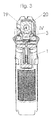
- the Fig. 1 shows a section through the plane of symmetry of a gun designed according to the invention, more precisely its handle 1.
- a trigger mechanism 2 together with tongue is entered and a slot 18 for a magazine is shown.
- the essential details of the device according to the invention are in Fig. 2 represented an enlargement of the detail II of the Fig. 1 is.
- an adapter 3 is inserted into the handle 1, which is provided in its upper part with guides 4 for the barrel and in its front, in the Fig. 2 left end portion a locking slot 6 ( Fig. 6 ), which is almost normal to the barrel axis 5 (in Fig. 2 entered only in their direction) runs.
- a locking slide 7 is slidably disposed, which is in an appropriate manner, in the illustrated embodiment via a groove and nose connection, with a latch 8 in operative connection.
- This lock 8 is either the original lock for the barrel of the weapon when using a conventional closure for firing normal ammunition, or a customized lock, which is adapted on the one hand to the weapon, on the other hand to the adapter.
- a further recess is provided, which allows a retaining slide 9 obliquely downwards and backwards, each seen in relation to the weapon to insert into the adapter.
- the shape of the retaining slide 9 is best Fig. 6 to see, the operation of the device will be off Fig. 2 most clearly:
- the handle 1 there are various configurations that allow the insertion and fixing of the adapter 3: on the one hand it is a stiffener 10, which connects the two cheeks of the handle 1 in this area above the tongue or its pivot bearing 13 together and mechanically stiffened. Another such component is the Floor 11, on which the return spring rests and which forms a support surface in its upper region. In addition, there is the lock 8 and the associated slot 12, which offer a further possibility for the introduction of an adapter 3.
- the compression spring shown in the figures in the area between the slot 12 and the pivot bearing 13 for the reins are of no particular interest here. The fixation is done as follows:
- the adapter 3 is pushed from behind and above with its retaining lug 14 under the stiffener 10 and placed in front with its support 15 on the upper edge of the bottom 11.
- the retaining slide 9 is then pushed in the insertion direction 16 in the slot provided for the adapter 3 and surrounds the stiffener 10 on the other side, as the retaining lug 14 and thus comes to a mechanically stable training.
- the lock 8 is pulled in its slot 12 by the user against the force of a spring (not shown) down and takes with its nose / groove connection the locking slide 7 down, whereby the barrel with the closure can be inserted. If then the lock 8 is released, it gets together with the locking slide 7 in the Fig. 2 shown position and fixes the barrel, which has a notch at the appropriate location on the guides 4. In one fixed the barrel 20, the retaining slide 9 in its position of use, since it prevents a displacement of the retaining slide upwards. It is possible in this way a mounting without the use of a tool.
- the adapter 3 at its rear end on a guide surface 17, which extends to the edge of the magazine shaft 18 and provides for the easy and reliable with low power supply to the next cartridge in the chamber. This is very useful, since the formation of the edge of the magazine shaft is adapted to the position of the Kipplaufes when inserting the next cartridge. In pistols with a rotary motion, the provision of such a guide surface is of little or no importance.
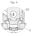
- the Fig. 3 is a section along the line III-III of Fig. 1 However, with attached exercise closure 19 and inserted exercise run 20.
- the adapter 3 and its support for the barrel 20 is clearly visible.
- FIG. 5 and 6 show the adapter 3 together with locking slide 7 and retaining slide 9, in Fig. 5 in plan view and in a section along the plane of symmetry and in Fig. 6 in a perspective exploded view, in which two mounting pins 21 are provided as a superplus, which can be used with appropriate design of the handle 1 for mounting the adapter 3 in the handle.
- a superplus means this because most existing grips have no openings for such mounting pins, but with the weakly loaded training ammunition, the attachment via the retaining lug 14, the support 15 and the retaining slide 9 is sufficient.
- the invention is not limited to the illustrated and illustrated embodiment, but may be variously modified. So it is in particular possible and even necessary to adapt the device including adapter to the respectively considered handle (its geometry) and the respective trigger mechanism (sliding trigger instead of rotating tongue, etc.). Even if the adapter will almost always be provided with a guide surface 17 to ensure the supply of the next cartridge, this is not as essential as securing the position of the training barrel by the guides 4. Whether the locking slider 7 is formed and arranged as shown depends again strongly on the geometry of the handle considered from; the same applies to the retaining slide 9 to an increased extent, since it can be dispensed with under certain circumstances, in particular, if the support 15 has a corresponding shape and under certain circumstances cooperates positively with the lock 8.
- the invention can thus also be defined as follows: It relates to an exercise weapon with a conventional handle 1 with a lock 8 for a tipping or a rotary run, with a trigger mechanism 2, which optionally has a pivot bearing 13 for a rotatable tongue, with a spring base 11, at that the return spring is supported; and with a practice closure 19 with a fixed exercise run 20.
- an adapter 3 is inserted, on the one hand above the trigger mechanism 2, optionally above the pivot bearing 13, to a stiffener 10 of the handle 1 and on the other hand in the upper area the spring base 11 of the handle 1 is supported, that the adapter 3 in its upper region guides 4 for the exercise run 20, and that the lock 8 with a locking slide 7, which is formed in a locking slot 6 of the adapter 3, cooperates, and that Locking slide 7 fixed the exercise run 20.
- the practice closure is distinguished visually (in terms of color) from the sharp closure, in order to reliably avoid confusion.
Landscapes
- Engineering & Computer Science (AREA)
- General Engineering & Computer Science (AREA)
- Toys (AREA)
- Aiming, Guidance, Guns With A Light Source, Armor, Camouflage, And Targets (AREA)
- Portable Nailing Machines And Staplers (AREA)
Abstract
Description
- Die Erfindung betrifft eine Übungswaffe, die den Rahmen einer herkömmlichen Pistole verwendet, aber einen speziellen Verschluss und verschiedene Adapter benutzt, entsprechend dem Oberbegriff des Anspruches 1.
- Üblicherweise werden zu Trainingszwecken Übungswaffen verwendet, die den echten Waffen von ihrer Handhabung her und damit von der äußeren Form, aber auch ihrer Masse her, möglichst entsprechen, optisch aber, beispielsweise durch spezielle Farbgebung, eine Verwechslung unmöglich machen, damit jeder Benutzer stets weiß, ob er eine richtige oder eine Übungswaffe vor sich hat.
- Es gibt allerdings seit einiger Zeit Bemühungen, bei derartigen Übungswaffen, die herkömmlichen Griffstückes, auch Rahmen genannt, zu verwenden und nur den Schlitten bzw. Verschluss durch einen Übungsverschluss auszutauschen. Ein solcher Austausch ist unbedingt notwendig, da ja Übungswaffen eine Munition verwenden, die nur eine minimale Ladung aufweist und daher die üblichen Verschlüsse durch die Aktion-Reaktion bzw. die Explosionsgase nicht ausreichend bewegt werden. Es kommt auch dazu, dass verschiedentlich auch bei ausreichendem Rücklauf Ladehemmung auftritt, da die Rückholfeder schwach ausgebildet sein muss und sie es daher verschiedentlich nicht schafft, die nächste Patrone beim Vorlauf des Schlittens in die Patronenkammer zu ziehen bzw. zu tauchen.
- Es ist Ziel und Aufgabe der Erfindung, hier eine Lösung anzugeben, durch die es ohne Verwendung von Werkzeug und somit auch außerhalb einer Waffenkammer möglich ist, einen entsprechenden Umbau vorzunehmen.
- Erfindungsgemäß werden diese Ziele durch die im kennzeichnenden Teil des Anspruches 1 angegebenen Merkmale erreicht; mit anderen Worten, es wird neben einem speziellen Schlitten samt bezüglich des Rahmens festem Lauf und Rückholfeder der Schieber, der bei der normalen Waffe die Vorwärtsbewegung des Laufes mit dem Schlitten, die beim Zerlegen notwendig ist, verhindert, dessen Rückwärtsbewegung nach Abgabe eines Schusses aber nicht, durch einen Adapter so verändert wird, dass er den Lauf gänzlich fixiert, da für Übungswaffen ein fester Lauf verwendet wird. Durch diese Maßnahme wird es möglich, auch Munition mit schwacher Ladung verwenden zu können und dabei doch die notwendige Bewegung des Schlittens zu generieren.
- Die Verwendung eines festen Laufes steht in gewissem Gegensatz zu den Einsatzwaffen mit Kipplauf, die beispielsweise in der
US 4,539,889 und/oder derUS 4,825,744 und/oder derUS 4,893,546 ausführlich beschrieben werden. Auf die Handstücke bzw. Griffstücke derartiger oder ähnlich ausgebildeter Waffen soll nun ein Verschluss (Schlitten) mit festem Lauf gesetzt werden, durch den die Waffe zu einer Übungswaffe wird. Der Inhalt der genannten Druckschriften wird für die Jurisdiktionen, in denen dies möglich ist, durch Bezugnahme zum Inhalt der vorliegenden Anmeldung gemacht. Neben Pistolen mit Kipplauf gibt es auch solche mit Drehlauf, die aber bezüglich der Erfindung ähnlich zu behandeln sind. - In einer Ausgestaltung ist vorgesehen, diese Verriegelung mit einem Adapter zu kombinieren, wobei dieser Adapter in Richtung zum Magazin hin eine spezielle Auflauffläche für die nächste in die Kammer einzuschiebende Patrone aufweist und so die im Stand der Technik speziell beim Kipplauf verschiedentlich auftauchenden Probleme zufolge des Höhenunterschiedes von Laufseelenachse und Magazin aus der Welt schafft.
- Die Erfindung wird im Folgenden anhand der Zeichnung näher erläutert, wobei als Griffstück eines entsprechend den oben genannten US-Patenten betrachtet wird, ohne die Erfindung darauf zu beschränken. Dabei zeigt bzw. zeigen:
- die
Fig. 1 einen schematischen Schnitt durch das Griffstück einer erfindungsgemäß ausgerüsteten Pistole, - die
Fig. 2 das Detail II derFig. 1 , - die
Fig. 3 einen Schnitt entlang der Linie III-III derFig. 1 , - die
Fig. 4 das Detail IV derFig. 3 , - die
Fig. 5 einen erfindungsgemäßen Adapter in Draufsicht und im Schnitt und - die
Fig. 6 eine perspektivische Ansicht eines erfindungsgemäßen Adapters samt Verriegelung, Verriegelungsschieber und Befestigungsstiften. - In der Beschreibung und den Ansprüchen werden die Begriffe "vorne", "hinten", "oben", "unten", "links", "rechts" und so weiter in der landläufigen Form und unter Bezugnahme auf eine Pistole, die in üblicher Weise gehalten wird, gebraucht. Das heißt, dass die Mündung des Laufes "vorne" ist, dass der Verschluss bzw. Schlitten durch die Explosionsgase nach "hinten" bewegt wird, etc..
- Die
Fig. 1 zeigt einen Schnitt durch die Symmetrieebene einer erfindungsgemäß ausgebildeten Pistole, genauer gesagt ihres Griffstückes 1. Ein Abzugsmechanismus 2 samt Züngel ist eingetragen und ein Schacht 18 für ein Magazin ist dargestellt. Die wesentlichen Details der erfindungsgemäßen Vorrichtung sind inFig. 2 dargestellt, die eine Vergrößerung des Details II derFig. 1 ist. Hier ist ersichtlich, dass ein Adapter 3 in das Griffstück 1 eingesetzt ist, der in seinem oberen Bereich mit Führungen 4 für den Lauf versehen ist und in seinem vorderen, in derFig. 2 linken, Endbereich einen Verriegelungsschlitz 6 (Fig. 6 ) aufweist, der nahezu normal zur Laufachse 5 (inFig. 2 nur ihrer Richtung nach eingetragen) verläuft. - Im Verriegelungsschlitz 6 ist ein Verriegelungsschieber 7 verschieblich angeordnet, der auf passende Weise, im dargestellten Ausführungsbeispiel über eine Nut- und Nasenverbindung, mit einer Verriegelung 8 in Wirkverbindung steht. Diese Verriegelung 8 ist entweder die Originalverriegelung für den Lauf der Waffe bei der Verwendung eines herkömmlichen Verschlusses zum Verschießen von normaler Munition, oder eine angepasste Verriegelung, die einerseits an die Waffe, andererseits an den Adapter angepasst ist.
- Im Adapter 3 ist eine weitere Ausnehmung vorgesehen, die es erlaubt, einen Halteschieber 9 schräg nach unten und hinten, jeweils gesehen in Bezug zur Waffe, in den Adapter einzuschieben. Die Form des Halteschiebers 9 ist am besten aus
Fig. 6 zu ersehen, die Funktionsweise der Vorrichtung wird ausFig. 2 am ehesten deutlich: - Im Griffstück 1 existieren verschiedene Ausbildungen, die das Einbringen und Fixieren des Adapters 3 erlauben: einerseits handelt es sich um eine Versteifung 10, die die beiden Wangen des Griffstückes 1 in diesem Bereich oberhalb des Züngels bzw dessen Drehlagers 13 miteinander verbindet und mechanisch versteift. Ein anderer derartiger Bauteil ist der Boden 11, auf dem die Rückholfeder anliegt und der in seinem oberen Bereich eine Auflagefläche ausbildet. Dazu kommt noch die Verriegelung 8 und der zugehörige Schlitz 12, die eine weitere Möglichkeit für die Einbringung eines Adapters 3 anbieten. Die in den Figuren dargestellte Druckfeder im Bereich zwischen dem Schlitz 12 und dem Drehlager 13 für das Züngel sind hier ohne besonderes Interesse. Die Fixierung erfolgt nun folgendermaßen:
- Nachdem der übliche Verschluss entfernt worden ist, wird der Adapter 3 von hinten und oben mit seiner Haltenase 14 unter die Versteifung 10 geschoben und vorne mit seinem Auflager 15 auf die Oberkante des Bodens 11 aufgesetzt. Zur Fixierung und der Erhöhung der mechanischen Stabilität wird sodann der Halteschieber 9 in Einschubrichtung 16 in den dafür vorgesehenen Schlitz des Adapters 3 geschoben und umfängt die Versteifung 10 auf der anderen Seite, wie die Haltenase 14 und kommt damit zu einer mechanisch stabilen Ausbildung.
- Wenn sodann der Trainingsverschluss aufgesetzt wird, so wird die Verriegelung 8 in ihrem Schlitz 12 vom Benutzer gegen die Kraft einer (nicht dargestellten) Feder nach unten gezogen und nimmt mit ihrer Nase/Nut-Verbindung den Verriegelungsschieber 7 mit nach unten, wodurch der Lauf mit dem Verschluss eingeschoben werden kann. Wenn dann die Verriegelung 8 freigegeben wird, gelangt sie samt dem Verriegelungsschieber 7 in die in
Fig. 2 dargestellte Position und fixiert den Lauf, der an der passenden Stelle eine Einkerbung hat, auf den Führungen 4. In einem fixiert der Lauf 20 den Halteschieber 9 in seiner Benutzungsposition, da er ein Verschieben des Halteschiebers nach oben verhindert. Es wird auf diese Weise eine Montage ohne Benutzung eines Werkzeuges ermöglicht. - Darüber hinaus weist der Adapter 3 an seinem hinteren Ende eine Führungsfläche 17 auf, die bis zum Rand des Magazinschachtes 18 reicht und für die leichte und auch mit geringer Kraft zuverlässig zu besorgende Zufuhr der nächsten Patrone in die Kammer sorgt. Dies ist sehr nützlich, da ja die Ausbildung des Randes des Magazinschachtes an die Position des Kipplaufes beim Einschieben der nächsten Patrone angepasst ist. Bei Pistolen mit Drehlauf ist das Vorsehen einer solchen Führungsfläche von geringer oder keiner Bedeutung.
- Die
Fig. 3 ist ein Schnitt entlang der Linie III-III derFig. 1 allerdings mit aufgesetztem Übungsverschluss 19 und eingesetztem Übungslauf 20. Der Adapter 3 und seine Halterung für den Lauf 20 ist deutlich ersichtlich. - Aus der
Fig. 4 , die das Detail III derFig. 3 zeigt, geht dies noch deutlicher hervor. - Die
Fig. 5 und6 zeigen einerseits den Adapter 3 samt Verriegelungsschieber 7 und Halteschieber 9, inFig. 5 in Draufsicht und in einem Schnitt entlang der Symmetrieebene und inFig. 6 in einer perspektivischen Explosionsdarstellung, bei der auch als Superplus zwei Befestigungsstifte 21 vorgesehen sind, die bei entsprechender Ausbildung des Griffstückes 1 zur Befestigung des Adapters 3 im Griffstück verwendet werden können. Ein Superplus bedeutet dies deshalb, weil bei den meisten existierenden Griffstücken keine Öffnungen für derartige Befestigungsstifte vorgesehen sind, doch ist bei der schwach geladenen Übungsmunition die Befestigung über die Haltenase 14, die Auflage 15 und den Halteschieber 9 ausreichend. - Die Erfindung ist nicht auf das dargestellte und erläuterte Ausführungsbeispiel begrenzt, sondern kann verschiedentlich abgewandelt werden. So ist es insbesondere möglich und sogar notwendig, die Vorrichtung samt Adapter an das jeweils betrachtete Griffstück (dessen Geometrie) und den jeweiligen Abzugsmechanismus (Schiebeabzug statt drehbarem Züngel, etc.) anzupassen. Auch wenn der Adapter zur Sicherstellung der Zufuhr der nächsten Patrone praktisch immer mit einer Führungsfläche 17 versehen sein wird, ist dies nicht so wesentlich wie die Sicherung der Position des Übungslaufes durch die Führungen 4. Ob der Verriegelungsschieber 7 wie dargestellt ausgebildet und angeordnet ist, hängt wiederum stark von der Geometrie des betrachteten Griffstückes ab; das Gleiche gilt für den Halteschieber 9 in erhöhtem Maße, da unter Umständen auf ihn verzichtet werden kann, insbesondere, wenn das Auflager 15 eine entsprechende Form aufweist und unter Umständen auch mit der Verriegelung 8 formschlüssig zusammenwirkt.
- Man kann die Erfindung somit auch folgendermaßen definieren: Sie betrifft eine Übungswaffe mit einem herkömmlichen Griffstück 1 mit einer Verriegelung 8 für einen Kipplauf oder einen Drehlauf, mit einem Abzugsmechanismus 2, der gegebenenfalls ein Drehlager 13 für ein verdrehbares Züngel aufweist, mit einem Federboden 11, an dem sich die Rückholfeder abstützt; und mit einem Übungsverschluss 19 mit einem festen Übungslauf 20.
- Sie ist zur Erreichung eines Umbaus ohne Benutzung eines Werkzeuges dadurch gekennzeichnet, dass in das Griffstück 1 ein Adapter 3 eingesetzt ist, der sich einerseits oberhalb des Abzugsmechanismus 2, gegebenenfalls oberhalb des Drehlagers 13, an einer Versteifung 10 des Griffstücks 1 und andererseits im oberen Bereich des Federbodens 11 des Griffstücks 1 abstützt, dass der Adapter 3 in seinem oberen Bereich Führungen 4 für den Übungslauf 20 aufweist, und dass die Verriegelung 8 mit einem Verriegelungsschieber 7, der in einem Verriegelungsschlitz 6 des Adapters 3 ausgebildet ist, zusammenwirkt, und dass der Verriegelungsschieber 7 den Übungslauf 20 fixiert.
- Als weiteren großen Vorteil soll darauf hingewiesen werden, dass es nicht notwendig ist, Teile des Griffstückes zu entfernen und in irgendeiner (stets unangenehmen) Weise zwischenzulagern, es wird nur der "scharfe" Verschluss abgenommen, der Adapter eingesetzt, der Übungsverschluss aufgesetzt und der Umbau ist fertig. Natürlich können Adapter und Übungsverschluss passend in einem Transportgehäuse untergebracht sein.
- Der Übungsverschluss ist aus Sicherheitsgründen bevorzugt optisch (farblich) auffällig vom scharfen Verschluss unterschieden, um Verwechslungen zuverlässig zu vermeiden.
Bezugszeichenliste: 01 Griffstück 12 Schlitz 02 Abzugsmechanismus 13 Drehlager 03 Adapter 14 Haltenase 04 Führungen 15 Auflager 05 Laufachse 16 Einschubrichtung 06 Verriegelungsschlitz 17 Führungsfläche 07 Verriegelungsschieber 18 Magazinschacht 08 Vernegelung 19 Übungsverschluss 09 Halteschieber 20 Übungslauf 10 Versteifung 21 Befestigungsstifte 11 Boden
Claims (5)
- Übungswaffe mit einem
herkömmlichen Griffstück (1) mit einer Verriegelung (8) für einen Kipplauf oder einen Drehlauf, mit einem Abzugsmechanismus (2), der gegebenenfalls ein Drehlager (13) für ein verdrehbares Züngel aufweist, mit einem Federboden (11), an dem sich die Rückholfeder abstützt; und mit einem
Übungsverschluss (19) mit einem festen Übungslauf (20),
dadurch gekennzeichnet, dass in das Griffstück (1) ein Adapter (3) eingesetzt ist, der sich einerseits oberhalb des Abzugsmechanismus (2), gegebenenfalls oberhalb des Drehlagers (13), an einer Versteifung (10) und andererseits im oberen Bereich des Federbodens (11) des Griffstücks (1) abstützt, dass der Adapter (3) in seinem oberen Bereich Führungen (4) für den Übungslauf (20) aufweist, und dass die Verriegelung (8) mit einem Verriegelungsschieber (7), der in einem Verriegelungsschlitz (6) des Adapters (3) ausgebildet ist, zusammenwirkt, und dass der Verriegelungsschieber (7) den Übungslauf (20) fixiert. - Übungswaffe nach Anspruch 1, dadurch gekennzeichnet, dass im Adapter (3) ein Halteschieber (9) vorgesehen ist, der in seiner Benutzerposition die Versteifung (10) oder einen adäquaten Teil des Griffstückes hintergreift und so den Adapter im Griffstück formschlüssig fixiert.
- Übungswaffe nach Anspruch 1 oder 2, dadurch gekennzeichnet, dass der Adapter (3) an seinem hinteren Ende eine Führungsfläche (17) für die nächste der Patronenkammer zuzuführende Patrone aufweist.
- Übungswaffe nach einem der Ansprüche 1 bis 3, dadurch gekennzeichnet, dass der Adapter (3) eine die Versteifung (10) zumindest teilweise umgreifende Haltenase (14) aufweist.
- Übungswaffe nach einem der Ansprüche 2 bis 4, dadurch gekennzeichnet, dass der Halteschieber (9) in seiner Benutzerposition vom Übungslauf (20) im Adapter (3) fixiert wird.
Priority Applications (4)
| Application Number | Priority Date | Filing Date | Title |
|---|---|---|---|
| ES16150133T ES2711537T3 (es) | 2016-01-05 | 2016-01-05 | Arma de entrenamiento |
| EP16150133.3A EP3190373B1 (de) | 2016-01-05 | 2016-01-05 | Übungswaffe |
| BR102017000092-3A BR102017000092B1 (pt) | 2016-01-05 | 2017-01-03 | Arma de treinamento |
| US15/399,633 US10209024B2 (en) | 2016-01-05 | 2017-01-05 | Practice weapon |
Applications Claiming Priority (1)
| Application Number | Priority Date | Filing Date | Title |
|---|---|---|---|
| EP16150133.3A EP3190373B1 (de) | 2016-01-05 | 2016-01-05 | Übungswaffe |
Publications (2)
| Publication Number | Publication Date |
|---|---|
| EP3190373A1 true EP3190373A1 (de) | 2017-07-12 |
| EP3190373B1 EP3190373B1 (de) | 2018-11-14 |
Family
ID=55070836
Family Applications (1)
| Application Number | Title | Priority Date | Filing Date |
|---|---|---|---|
| EP16150133.3A Active EP3190373B1 (de) | 2016-01-05 | 2016-01-05 | Übungswaffe |
Country Status (4)
| Country | Link |
|---|---|
| US (1) | US10209024B2 (de) |
| EP (1) | EP3190373B1 (de) |
| BR (1) | BR102017000092B1 (de) |
| ES (1) | ES2711537T3 (de) |
Cited By (1)
| Publication number | Priority date | Publication date | Assignee | Title |
|---|---|---|---|---|
| EP3754287A1 (de) * | 2019-06-19 | 2020-12-23 | Glock Technology GmbH | Pistole mit starrem lauf, insbesondere trainingswaffe |
Families Citing this family (7)
| Publication number | Priority date | Publication date | Assignee | Title |
|---|---|---|---|---|
| EP3179193B1 (de) | 2015-12-10 | 2018-06-27 | Glock Technology GmbH | Pistole mit drehlauf |
| ES2711537T3 (es) | 2016-01-05 | 2019-05-06 | Glock Tech Gmbh | Arma de entrenamiento |
| ES2712697T3 (es) * | 2016-02-10 | 2019-05-14 | Glock Tech Gmbh | Pistola |
| EP3367040B1 (de) | 2017-02-27 | 2019-10-30 | Glock Technology GmbH | Pistole |
| WO2019236025A2 (en) * | 2018-02-15 | 2019-12-12 | Norsmak Maki̇na Ve Kalip San. Ti̇c. Ltd. Şti̇. | A barrel tilting mechanism |
| US11067350B1 (en) * | 2018-10-31 | 2021-07-20 | Lone Wolf Distributors, Inc. | Handgun frame conversion system |
| US11029118B1 (en) * | 2019-01-12 | 2021-06-08 | Brian Williams | Firearm assembly having a locking block and slide |
Citations (4)
| Publication number | Priority date | Publication date | Assignee | Title |
|---|---|---|---|---|
| US2817174A (en) * | 1954-08-17 | 1957-12-24 | High Standard Mfg Corp | Take-down device for firearms |
| US4539889A (en) | 1981-04-30 | 1985-09-10 | Gaston Glock | Automatic pistol with counteracting spring control mechanism |
| US6276252B1 (en) * | 1997-05-23 | 2001-08-21 | Snc Technologies Inc. | Ammunition chambering mechanism for automatic firearms |
| DE60003990T2 (de) * | 1999-04-23 | 2004-06-03 | Snc Technologies Inc., Le Gardeur | Zweiteiliger pistolenlauf für eine niedrigenergiemunition |
Family Cites Families (8)
| Publication number | Priority date | Publication date | Assignee | Title |
|---|---|---|---|---|
| US2107359A (en) | 1935-05-06 | 1938-02-08 | Mauser Werke Ag | Barrel-holding device for automatic pistols |
| BE789209A (fr) | 1971-09-24 | 1973-01-15 | Colt Ind Operating Corp | Verrou pour la culasse et mecanisme de demontage pour un pistolet automatique |
| DE19507993C2 (de) | 1995-03-07 | 1998-08-06 | Walther Carl Gmbh | Laufhalterung für Schußwaffen |
| US7823314B1 (en) | 2008-12-02 | 2010-11-02 | Wheatley Craig A | Firearm with a detachable barrel and suppressed barrel assembly |
| AT510442B1 (de) | 2011-08-24 | 2012-04-15 | Wilhelm Bubits | Pistole mit verriegelung durch verriegelungskörper |
| US8950100B2 (en) | 2011-12-09 | 2015-02-10 | Sturm, Ruger & Company, Inc. | Slide takedown system and method for firearm |
| DE102013010969B3 (de) | 2013-07-01 | 2014-10-16 | Heckler & Koch Gmbh | Demontagesicherungsvorrichtung einer Selbstladepistole und Selbstladepistole mit einer Demontagesicherungsvorrichtung |
| ES2711537T3 (es) | 2016-01-05 | 2019-05-06 | Glock Tech Gmbh | Arma de entrenamiento |
-
2016
- 2016-01-05 ES ES16150133T patent/ES2711537T3/es active Active
- 2016-01-05 EP EP16150133.3A patent/EP3190373B1/de active Active
-
2017
- 2017-01-03 BR BR102017000092-3A patent/BR102017000092B1/pt active IP Right Grant
- 2017-01-05 US US15/399,633 patent/US10209024B2/en active Active
Patent Citations (6)
| Publication number | Priority date | Publication date | Assignee | Title |
|---|---|---|---|---|
| US2817174A (en) * | 1954-08-17 | 1957-12-24 | High Standard Mfg Corp | Take-down device for firearms |
| US4539889A (en) | 1981-04-30 | 1985-09-10 | Gaston Glock | Automatic pistol with counteracting spring control mechanism |
| US4825744A (en) | 1981-04-30 | 1989-05-02 | Gaston Glock | Automatic pistol |
| US4893546A (en) | 1981-04-30 | 1990-01-16 | Gaston Glock | Automatic pistol |
| US6276252B1 (en) * | 1997-05-23 | 2001-08-21 | Snc Technologies Inc. | Ammunition chambering mechanism for automatic firearms |
| DE60003990T2 (de) * | 1999-04-23 | 2004-06-03 | Snc Technologies Inc., Le Gardeur | Zweiteiliger pistolenlauf für eine niedrigenergiemunition |
Cited By (2)
| Publication number | Priority date | Publication date | Assignee | Title |
|---|---|---|---|---|
| EP3754287A1 (de) * | 2019-06-19 | 2020-12-23 | Glock Technology GmbH | Pistole mit starrem lauf, insbesondere trainingswaffe |
| US11530894B2 (en) | 2019-06-19 | 2022-12-20 | Glock Technology Gmbh | Pistol having a rigid barrel, in particular training weapon |
Also Published As
| Publication number | Publication date |
|---|---|
| BR102017000092B1 (pt) | 2023-04-18 |
| ES2711537T3 (es) | 2019-05-06 |
| BR102017000092A2 (pt) | 2017-07-11 |
| US10209024B2 (en) | 2019-02-19 |
| US20170191784A1 (en) | 2017-07-06 |
| EP3190373B1 (de) | 2018-11-14 |
Similar Documents
| Publication | Publication Date | Title |
|---|---|---|
| EP3190373B1 (de) | Übungswaffe | |
| DE10229847B3 (de) | Maschinengewehr | |
| DE102017106581A1 (de) | Gehäuseteil mit einem beidhändigen bolzenanschlag | |
| DE10055578B4 (de) | Schlossmechanismus für Gewehre | |
| DE69928596T2 (de) | Vorrichtung zum Kontrollieren des Munitionszuführsystems in einem Vorderschaftrepetierer | |
| EP0801284B1 (de) | Ladehebelanordnung | |
| EP1692451B1 (de) | Verschlusssperre | |
| DE3014541C2 (de) | Hebelverschluß für das Verriegeln und Entriegeln des Laufs von tragbaren automatischen Schußwaffen | |
| DE3928125A1 (de) | Durchladeeinrichtung fuer selbstladende handfeuerwaffen | |
| DE10122345C1 (de) | Maschinengewehr mit Spannschieber | |
| EP1672306A1 (de) | Pistole | |
| DE102009057864B4 (de) | Handfeuerwaffe | |
| DE607587C (de) | Feuerwaffe mit auswechselbarem Lauf | |
| DE102004029205B3 (de) | Handfeuerwaffe und starre Schulterstütze hierfür | |
| DE10008979B4 (de) | Mehrlade-Handfeuerwaffe mit lösbarer Verschlußsperre | |
| DE3305773C2 (de) | ||
| EP1147363B1 (de) | Anordnung zum öffnen der staubklappen einer handfeuerwaffe | |
| DE232735C (de) | ||
| EP4177562B1 (de) | Jagd- oder sportwaffe mit verbesserter magazinanordnung | |
| DE157628C (de) | ||
| DE94726C (de) | ||
| DE60317005T2 (de) | Sicherheitsvorrichtung für den Verschluss einer Schusswaffe | |
| CH663275A5 (de) | Faustfeuerwaffe. | |
| DE93533C (de) | ||
| AT139546B (de) | Kastenmagazin für Selbstladewaffen. |
Legal Events
| Date | Code | Title | Description |
|---|---|---|---|
| PUAI | Public reference made under article 153(3) epc to a published international application that has entered the european phase |
Free format text: ORIGINAL CODE: 0009012 |
|
| STAA | Information on the status of an ep patent application or granted ep patent |
Free format text: STATUS: THE APPLICATION HAS BEEN PUBLISHED |
|
| AK | Designated contracting states |
Kind code of ref document: A1 Designated state(s): AL AT BE BG CH CY CZ DE DK EE ES FI FR GB GR HR HU IE IS IT LI LT LU LV MC MK MT NL NO PL PT RO RS SE SI SK SM TR |
|
| AX | Request for extension of the european patent |
Extension state: BA ME |
|
| STAA | Information on the status of an ep patent application or granted ep patent |
Free format text: STATUS: REQUEST FOR EXAMINATION WAS MADE |
|
| 17P | Request for examination filed |
Effective date: 20180112 |
|
| RAX | Requested extension states of the european patent have changed |
Extension state: ME Payment date: 20180112 Extension state: BA Payment date: 20180112 |
|
| RBV | Designated contracting states (corrected) |
Designated state(s): AL AT BE BG CH CY CZ DE DK EE ES FI FR GB GR HR HU IE IS IT LI LT LU LV MC MK MT NL NO PL PT RO RS SE SI SK SM TR |
|
| GRAP | Despatch of communication of intention to grant a patent |
Free format text: ORIGINAL CODE: EPIDOSNIGR1 |
|
| STAA | Information on the status of an ep patent application or granted ep patent |
Free format text: STATUS: GRANT OF PATENT IS INTENDED |
|
| RIC1 | Information provided on ipc code assigned before grant |
Ipc: F41A 21/26 20060101AFI20180517BHEP Ipc: F41A 5/06 20060101ALN20180517BHEP Ipc: F41A 21/48 20060101ALI20180517BHEP Ipc: F41A 5/04 20060101ALN20180517BHEP Ipc: F41A 33/00 20060101ALI20180517BHEP |
|
| INTG | Intention to grant announced |
Effective date: 20180531 |
|
| GRAS | Grant fee paid |
Free format text: ORIGINAL CODE: EPIDOSNIGR3 |
|
| GRAA | (expected) grant |
Free format text: ORIGINAL CODE: 0009210 |
|
| STAA | Information on the status of an ep patent application or granted ep patent |
Free format text: STATUS: THE PATENT HAS BEEN GRANTED |
|
| AK | Designated contracting states |
Kind code of ref document: B1 Designated state(s): AL AT BE BG CH CY CZ DE DK EE ES FI FR GB GR HR HU IE IS IT LI LT LU LV MC MK MT NL NO PL PT RO RS SE SI SK SM TR |
|
| AX | Request for extension of the european patent |
Extension state: BA ME |
|
| REG | Reference to a national code |
Ref country code: CH Ref legal event code: EP Ref country code: AT Ref legal event code: REF Ref document number: 1065345 Country of ref document: AT Kind code of ref document: T Effective date: 20181115 |
|
| REG | Reference to a national code |
Ref country code: DE Ref legal event code: R096 Ref document number: 502016002459 Country of ref document: DE |
|
| REG | Reference to a national code |
Ref country code: IE Ref legal event code: FG4D Free format text: LANGUAGE OF EP DOCUMENT: GERMAN |
|
| REG | Reference to a national code |
Ref country code: NL Ref legal event code: MP Effective date: 20181114 |
|
| REG | Reference to a national code |
Ref country code: LT Ref legal event code: MG4D |
|
| PG25 | Lapsed in a contracting state [announced via postgrant information from national office to epo] |
Ref country code: LT Free format text: LAPSE BECAUSE OF FAILURE TO SUBMIT A TRANSLATION OF THE DESCRIPTION OR TO PAY THE FEE WITHIN THE PRESCRIBED TIME-LIMIT Effective date: 20181114 Ref country code: BG Free format text: LAPSE BECAUSE OF FAILURE TO SUBMIT A TRANSLATION OF THE DESCRIPTION OR TO PAY THE FEE WITHIN THE PRESCRIBED TIME-LIMIT Effective date: 20190214 Ref country code: NO Free format text: LAPSE BECAUSE OF FAILURE TO SUBMIT A TRANSLATION OF THE DESCRIPTION OR TO PAY THE FEE WITHIN THE PRESCRIBED TIME-LIMIT Effective date: 20190214 Ref country code: FI Free format text: LAPSE BECAUSE OF FAILURE TO SUBMIT A TRANSLATION OF THE DESCRIPTION OR TO PAY THE FEE WITHIN THE PRESCRIBED TIME-LIMIT Effective date: 20181114 Ref country code: IS Free format text: LAPSE BECAUSE OF FAILURE TO SUBMIT A TRANSLATION OF THE DESCRIPTION OR TO PAY THE FEE WITHIN THE PRESCRIBED TIME-LIMIT Effective date: 20190314 Ref country code: LV Free format text: LAPSE BECAUSE OF FAILURE TO SUBMIT A TRANSLATION OF THE DESCRIPTION OR TO PAY THE FEE WITHIN THE PRESCRIBED TIME-LIMIT Effective date: 20181114 Ref country code: HR Free format text: LAPSE BECAUSE OF FAILURE TO SUBMIT A TRANSLATION OF THE DESCRIPTION OR TO PAY THE FEE WITHIN THE PRESCRIBED TIME-LIMIT Effective date: 20181114 |
|
| REG | Reference to a national code |
Ref country code: ES Ref legal event code: FG2A Ref document number: 2711537 Country of ref document: ES Kind code of ref document: T3 Effective date: 20190506 |
|
| PG25 | Lapsed in a contracting state [announced via postgrant information from national office to epo] |
Ref country code: SE Free format text: LAPSE BECAUSE OF FAILURE TO SUBMIT A TRANSLATION OF THE DESCRIPTION OR TO PAY THE FEE WITHIN THE PRESCRIBED TIME-LIMIT Effective date: 20181114 Ref country code: NL Free format text: LAPSE BECAUSE OF FAILURE TO SUBMIT A TRANSLATION OF THE DESCRIPTION OR TO PAY THE FEE WITHIN THE PRESCRIBED TIME-LIMIT Effective date: 20181114 Ref country code: AL Free format text: LAPSE BECAUSE OF FAILURE TO SUBMIT A TRANSLATION OF THE DESCRIPTION OR TO PAY THE FEE WITHIN THE PRESCRIBED TIME-LIMIT Effective date: 20181114 Ref country code: PT Free format text: LAPSE BECAUSE OF FAILURE TO SUBMIT A TRANSLATION OF THE DESCRIPTION OR TO PAY THE FEE WITHIN THE PRESCRIBED TIME-LIMIT Effective date: 20190314 Ref country code: GR Free format text: LAPSE BECAUSE OF FAILURE TO SUBMIT A TRANSLATION OF THE DESCRIPTION OR TO PAY THE FEE WITHIN THE PRESCRIBED TIME-LIMIT Effective date: 20190215 Ref country code: RS Free format text: LAPSE BECAUSE OF FAILURE TO SUBMIT A TRANSLATION OF THE DESCRIPTION OR TO PAY THE FEE WITHIN THE PRESCRIBED TIME-LIMIT Effective date: 20181114 |
|
| PG25 | Lapsed in a contracting state [announced via postgrant information from national office to epo] |
Ref country code: PL Free format text: LAPSE BECAUSE OF FAILURE TO SUBMIT A TRANSLATION OF THE DESCRIPTION OR TO PAY THE FEE WITHIN THE PRESCRIBED TIME-LIMIT Effective date: 20181114 Ref country code: CZ Free format text: LAPSE BECAUSE OF FAILURE TO SUBMIT A TRANSLATION OF THE DESCRIPTION OR TO PAY THE FEE WITHIN THE PRESCRIBED TIME-LIMIT Effective date: 20181114 Ref country code: DK Free format text: LAPSE BECAUSE OF FAILURE TO SUBMIT A TRANSLATION OF THE DESCRIPTION OR TO PAY THE FEE WITHIN THE PRESCRIBED TIME-LIMIT Effective date: 20181114 |
|
| REG | Reference to a national code |
Ref country code: DE Ref legal event code: R097 Ref document number: 502016002459 Country of ref document: DE |
|
| PG25 | Lapsed in a contracting state [announced via postgrant information from national office to epo] |
Ref country code: MC Free format text: LAPSE BECAUSE OF FAILURE TO SUBMIT A TRANSLATION OF THE DESCRIPTION OR TO PAY THE FEE WITHIN THE PRESCRIBED TIME-LIMIT Effective date: 20181114 Ref country code: RO Free format text: LAPSE BECAUSE OF FAILURE TO SUBMIT A TRANSLATION OF THE DESCRIPTION OR TO PAY THE FEE WITHIN THE PRESCRIBED TIME-LIMIT Effective date: 20181114 Ref country code: EE Free format text: LAPSE BECAUSE OF FAILURE TO SUBMIT A TRANSLATION OF THE DESCRIPTION OR TO PAY THE FEE WITHIN THE PRESCRIBED TIME-LIMIT Effective date: 20181114 Ref country code: SM Free format text: LAPSE BECAUSE OF FAILURE TO SUBMIT A TRANSLATION OF THE DESCRIPTION OR TO PAY THE FEE WITHIN THE PRESCRIBED TIME-LIMIT Effective date: 20181114 Ref country code: SK Free format text: LAPSE BECAUSE OF FAILURE TO SUBMIT A TRANSLATION OF THE DESCRIPTION OR TO PAY THE FEE WITHIN THE PRESCRIBED TIME-LIMIT Effective date: 20181114 |
|
| REG | Reference to a national code |
Ref country code: CH Ref legal event code: PL |
|
| PLBE | No opposition filed within time limit |
Free format text: ORIGINAL CODE: 0009261 |
|
| STAA | Information on the status of an ep patent application or granted ep patent |
Free format text: STATUS: NO OPPOSITION FILED WITHIN TIME LIMIT |
|
| PG25 | Lapsed in a contracting state [announced via postgrant information from national office to epo] |
Ref country code: LU Free format text: LAPSE BECAUSE OF NON-PAYMENT OF DUE FEES Effective date: 20190105 |
|
| 26N | No opposition filed |
Effective date: 20190815 |
|
| REG | Reference to a national code |
Ref country code: IE Ref legal event code: MM4A |
|
| PG25 | Lapsed in a contracting state [announced via postgrant information from national office to epo] |
Ref country code: SI Free format text: LAPSE BECAUSE OF FAILURE TO SUBMIT A TRANSLATION OF THE DESCRIPTION OR TO PAY THE FEE WITHIN THE PRESCRIBED TIME-LIMIT Effective date: 20181114 |
|
| PG25 | Lapsed in a contracting state [announced via postgrant information from national office to epo] |
Ref country code: LI Free format text: LAPSE BECAUSE OF NON-PAYMENT OF DUE FEES Effective date: 20190131 Ref country code: CH Free format text: LAPSE BECAUSE OF NON-PAYMENT OF DUE FEES Effective date: 20190131 |
|
| PG25 | Lapsed in a contracting state [announced via postgrant information from national office to epo] |
Ref country code: IE Free format text: LAPSE BECAUSE OF NON-PAYMENT OF DUE FEES Effective date: 20190105 |
|
| PG25 | Lapsed in a contracting state [announced via postgrant information from national office to epo] |
Ref country code: TR Free format text: LAPSE BECAUSE OF FAILURE TO SUBMIT A TRANSLATION OF THE DESCRIPTION OR TO PAY THE FEE WITHIN THE PRESCRIBED TIME-LIMIT Effective date: 20181114 |
|
| PG25 | Lapsed in a contracting state [announced via postgrant information from national office to epo] |
Ref country code: MT Free format text: LAPSE BECAUSE OF FAILURE TO SUBMIT A TRANSLATION OF THE DESCRIPTION OR TO PAY THE FEE WITHIN THE PRESCRIBED TIME-LIMIT Effective date: 20181114 |
|
| GBPC | Gb: european patent ceased through non-payment of renewal fee |
Effective date: 20200105 |
|
| PG25 | Lapsed in a contracting state [announced via postgrant information from national office to epo] |
Ref country code: GB Free format text: LAPSE BECAUSE OF NON-PAYMENT OF DUE FEES Effective date: 20200105 |
|
| PG25 | Lapsed in a contracting state [announced via postgrant information from national office to epo] |
Ref country code: CY Free format text: LAPSE BECAUSE OF FAILURE TO SUBMIT A TRANSLATION OF THE DESCRIPTION OR TO PAY THE FEE WITHIN THE PRESCRIBED TIME-LIMIT Effective date: 20181114 |
|
| PG25 | Lapsed in a contracting state [announced via postgrant information from national office to epo] |
Ref country code: HU Free format text: LAPSE BECAUSE OF FAILURE TO SUBMIT A TRANSLATION OF THE DESCRIPTION OR TO PAY THE FEE WITHIN THE PRESCRIBED TIME-LIMIT; INVALID AB INITIO Effective date: 20160105 |
|
| PG25 | Lapsed in a contracting state [announced via postgrant information from national office to epo] |
Ref country code: MK Free format text: LAPSE BECAUSE OF FAILURE TO SUBMIT A TRANSLATION OF THE DESCRIPTION OR TO PAY THE FEE WITHIN THE PRESCRIBED TIME-LIMIT Effective date: 20181114 |
|
| P01 | Opt-out of the competence of the unified patent court (upc) registered |
Effective date: 20230601 |
|
| PGFP | Annual fee paid to national office [announced via postgrant information from national office to epo] |
Ref country code: FR Payment date: 20231227 Year of fee payment: 9 |
|
| PGFP | Annual fee paid to national office [announced via postgrant information from national office to epo] |
Ref country code: BE Payment date: 20231228 Year of fee payment: 9 |
|
| PGFP | Annual fee paid to national office [announced via postgrant information from national office to epo] |
Ref country code: ES Payment date: 20240209 Year of fee payment: 9 |
|
| PGFP | Annual fee paid to national office [announced via postgrant information from national office to epo] |
Ref country code: AT Payment date: 20240118 Year of fee payment: 9 |
|
| PGFP | Annual fee paid to national office [announced via postgrant information from national office to epo] |
Ref country code: DE Payment date: 20231228 Year of fee payment: 9 |
|
| PGFP | Annual fee paid to national office [announced via postgrant information from national office to epo] |
Ref country code: IT Payment date: 20240105 Year of fee payment: 9 |