EP3190298A1 - Anordnung zur lösbaren befestigung von bauteilen - Google Patents
Anordnung zur lösbaren befestigung von bauteilen Download PDFInfo
- Publication number
- EP3190298A1 EP3190298A1 EP17150219.8A EP17150219A EP3190298A1 EP 3190298 A1 EP3190298 A1 EP 3190298A1 EP 17150219 A EP17150219 A EP 17150219A EP 3190298 A1 EP3190298 A1 EP 3190298A1
- Authority
- EP
- European Patent Office
- Prior art keywords
- component
- sleeve
- disc
- blind rivet
- compensating
- Prior art date
- Legal status (The legal status is an assumption and is not a legal conclusion. Google has not performed a legal analysis and makes no representation as to the accuracy of the status listed.)
- Granted
Links
Images

Classifications
-
- F—MECHANICAL ENGINEERING; LIGHTING; HEATING; WEAPONS; BLASTING
- F16—ENGINEERING ELEMENTS AND UNITS; GENERAL MEASURES FOR PRODUCING AND MAINTAINING EFFECTIVE FUNCTIONING OF MACHINES OR INSTALLATIONS; THERMAL INSULATION IN GENERAL
- F16B—DEVICES FOR FASTENING OR SECURING CONSTRUCTIONAL ELEMENTS OR MACHINE PARTS TOGETHER, e.g. NAILS, BOLTS, CIRCLIPS, CLAMPS, CLIPS OR WEDGES; JOINTS OR JOINTING
- F16B5/00—Joining sheets or plates, e.g. panels, to one another or to strips or bars parallel to them
- F16B5/02—Joining sheets or plates, e.g. panels, to one another or to strips or bars parallel to them by means of fastening members using screw-thread
- F16B5/0216—Joining sheets or plates, e.g. panels, to one another or to strips or bars parallel to them by means of fastening members using screw-thread the position of the plates to be connected being adjustable
- F16B5/0233—Joining sheets or plates, e.g. panels, to one another or to strips or bars parallel to them by means of fastening members using screw-thread the position of the plates to be connected being adjustable allowing for adjustment perpendicular to the plane of the plates
-
- F—MECHANICAL ENGINEERING; LIGHTING; HEATING; WEAPONS; BLASTING
- F16—ENGINEERING ELEMENTS AND UNITS; GENERAL MEASURES FOR PRODUCING AND MAINTAINING EFFECTIVE FUNCTIONING OF MACHINES OR INSTALLATIONS; THERMAL INSULATION IN GENERAL
- F16B—DEVICES FOR FASTENING OR SECURING CONSTRUCTIONAL ELEMENTS OR MACHINE PARTS TOGETHER, e.g. NAILS, BOLTS, CIRCLIPS, CLAMPS, CLIPS OR WEDGES; JOINTS OR JOINTING
- F16B5/00—Joining sheets or plates, e.g. panels, to one another or to strips or bars parallel to them
- F16B5/02—Joining sheets or plates, e.g. panels, to one another or to strips or bars parallel to them by means of fastening members using screw-thread
- F16B5/025—Joining sheets or plates, e.g. panels, to one another or to strips or bars parallel to them by means of fastening members using screw-thread specially designed to compensate for misalignement or to eliminate unwanted play
-
- F—MECHANICAL ENGINEERING; LIGHTING; HEATING; WEAPONS; BLASTING
- F16—ENGINEERING ELEMENTS AND UNITS; GENERAL MEASURES FOR PRODUCING AND MAINTAINING EFFECTIVE FUNCTIONING OF MACHINES OR INSTALLATIONS; THERMAL INSULATION IN GENERAL
- F16B—DEVICES FOR FASTENING OR SECURING CONSTRUCTIONAL ELEMENTS OR MACHINE PARTS TOGETHER, e.g. NAILS, BOLTS, CIRCLIPS, CLAMPS, CLIPS OR WEDGES; JOINTS OR JOINTING
- F16B5/00—Joining sheets or plates, e.g. panels, to one another or to strips or bars parallel to them
- F16B5/02—Joining sheets or plates, e.g. panels, to one another or to strips or bars parallel to them by means of fastening members using screw-thread
- F16B5/0283—Joining sheets or plates, e.g. panels, to one another or to strips or bars parallel to them by means of fastening members using screw-thread with an externally threaded sleeve around the neck or the head of the screw-threaded element for adjustably fastening a plate or frame or the like to a fixed element
Definitions
- the present invention relates to an arrangement for the releasable attachment of components with means for compensating for tolerances in the attachment of a component (2) to a component (1) according to the preamble of claim 1.
- Such arrangements or systems find i.a. in the attachment of components, in particular of cladding to predetermined interior and / or exterior structures of vehicles application. Tolerance compensation between such components is done so far in the interior often by gluing or by shimming in the outdoor area.
- fastening systems with tolerance compensation between two components which can be connected to each other at a distance from one another are also known from the prior art.
- a fastening device with tolerance compensation, which consists of a base member in the form of a blind rivet nut, an adjustment and a fastening screw.
- the blind rivet nut can be fixed to the component A and has two axially staggered internal threads, one of which forms a thread pairing of a first gear direction with an external thread of the adjusting bush and the other thread forms a thread pairing of an opposite second gear direction with the thread of the fastening screw.
- the adjusting sleeve is provided with circumferentially distributed resilient fingers that create when screwing the mounting screws in the adjusting bush to the thread of the screw and form with this a so-called Mitschleppharm.
- a device for captively connecting two spaced-apart components with the possibility of exchanging the moving parts at a later time to be able to. It is essential that the support device is connected to the component via a bayonet lock. A tolerance compensation can not be done without dismantling a component.
- a tolerance compensation arrangement which consists of a screw, designed as a blind rivet nut, a balance bush and a locknut.
- the balance bush is provided with an internal and an external thread, so that on the one hand the compensating bushing in the nut and on the other hand, the screw in the compensating bush is screwed.
- the compensating bushing is manually removed from the nut by means of a tool until it rests against the first component, whereupon the compensating bushing is secured with the counter nut and thus the two components are braced.
- a fastening system for fastening a component B to a component A while compensating for tolerances.
- This includes a screw, a blind rivet nut with an internal thread and a compensating bushing, wherein a clamping cone is provided which can be inserted into the compensating bushing and connected to this captive.
- the compensating bush and the clamping cone in the assembled state form a unit as a screw base.
- the present invention has for its object to provide an arrangement for releasably securing a component to another component, which is designed with means for compensating for manufacturing and / or assembly-related tolerances between the first and the second component.
- a rotary member which has a sleeve fixedly connected to the second component and a disc mounted in the sleeve and rotatable therein.
- the disc is connected via a fastening screw with a blind rivet nut and thus with the first component, wherein the second component is removable.
- the said disk has for this purpose an external thread and on the side directed toward the second component of the disk engagement points are provided for a setting tool for tolerance compensation.
- the sleeve of the rotary part has an internal thread and a rim directed towards the second component, which is provided as an adhesive surface for connection to the second component.
- the sleeve of the rotary member can be screwed on the side of the second component, for example, an outer lining of a vehicle, a cap.
- the arrangement is used in particular the releasable attachment of a panel to a structure, in particular a vehicle structure.
- the arrangement further comprises means for compensating manufacturing and / or assembly-related tolerances between the first and a second component.
- the arrangement comprises a blind rivet nut 5 with an internal thread and a fastening screw 4.
- the blind rivet nut 5 is in the component 1, ie the vehicle structure is positioned.
- the outer lining a rotary member 3 is provided, which is a firmly connected to the component 2 sleeve 3.1 and a mounted in the sleeve 3.1 and rotatable therein disc 3.2 having.
- the sleeve 3.1 is first glued firmly in the region of the collar 3.1.1 with the component 2 (here outer lining) or connected in another way (positive, positive or material fit) with the component 2. Then the disc 3.2 is screwed into the sleeve 3.1. Subsequently, the positioning of the component to be fastened 2 (eg cladding panel) on the attachment points (position of Blindnietmutter 5) in the shell of the structure or the component 1.
- the blind rivet nut 5 has for this purpose a circumferential collar 5.1 and the disc 3.2 a corresponding release 3.2 .1 for the collar of the blind rivet nut 5.
- the component 2 is placed with the rotary part 3 on the blind rivet nut.
- the tolerance compensation takes place.
- the tool 7 engages in the engagement points 3.3 of the disk 3.2 and attracts to compensate for manufacturing and / or assembly-related tolerances the disk 3.2 in the sleeve 3.1 at.
- the rotary member 3 is fixed by means of the fastening screw 4 in the blind rivet nut 5 and thus in the component 1 (the vehicle structure).
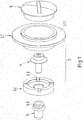
- the above items of the arrangement are in the Fig. 1 shown in an exploded view.
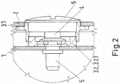
- the arrangement is shown in a sectional view in the mounted state, ie, the outer lining (component 2) is fixed by means of the arrangement on the structure (component 1).
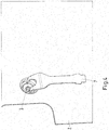
- the operating principle of the system is in the Fig. 3 clarified.
- the sleeve 3.1 of the rotary member 3 can be provided on the side of the component 2 with a cap 6, which can be plugged or screwed.
- the cap is screwed with the back of the special tool in the internal thread and thus the screw 4 covered. This allows a visually beautiful exterior design.
- the tool 7 has, in addition to the means for engaging in the engagement point 3.3 of the disc 3.2, on its back a screwdriver similar design, with which the cap 6 can be screwed.
Landscapes
- Engineering & Computer Science (AREA)
- General Engineering & Computer Science (AREA)
- Mechanical Engineering (AREA)
- Connection Of Plates (AREA)
- Dowels (AREA)
Abstract
Description
- Die vorliegende Erfindung betrifft eine Anordnung zur lösbaren Befestigung von Bauteilen mit Mitteln zum Ausgleich von Toleranzen bei der Befestigung eines Bauteils (2) an einem Bauteil (1) nach dem Oberbegriff des Anspruchs 1.
- Derartige Anordnungen oder Systeme finden u.a. bei der Befestigung von Bauteilen, insbesondere von Verkleidungen an vorgegebenen Innen- und/oder Außenstrukturen von Fahrzeugen Anwendung. Ein Toleranzausgleich zwischen derartigen Bauteilen erfolgt bislang im Innenbereich häufig durch Kleben oder durch Shimmen im Außenbereich. Aus dem Stand der Technik sind aber auch Befestigungssysteme mit Toleranzausgleich zwischen zwei miteinander im Abstand zueinander verbindbaren Bauteilen bekannt.
- In der
DE 10151383 A1 wird eine Befestigungseinrichtung mit Toleranzausgleich offenbart, die aus einem Basiselement in Form einer Blindnietmutter, einer Verstellbuchse und einer Befestigungsschraube besteht. Die Blindnietmutter ist an dem Bauteil A festlegbar und weist zwei axial gegeneinander versetzte Innengewinde auf, von denen das eine mit einem Außengewinde der Verstellbuchse eine Gewindepaarung einer ersten Gangrichtung bildet und das andere Gewinde mit dem Gewinde der Befestigungsschraube eine Gewindepaarung einer entgegengesetzten zweiten Gangrichtung bildet. Die Verstellbuchse ist mit über den Umfang verteilten federnden Fingern versehen, die sich beim Einschrauben der Befestigungsschrauben in die Verstellbuchse an das Gewinde der Schraube anlegen und mit dieser eine sogenannte Mitschleppverbindung bilden. Beim Eindrehen der Schraube wird daher die Verstellbuchse mitgedreht und hierdurch aus der Blindnietmutter herausgeschraubt, bis sich ein Flansch der Verstellbuchse zwecks Toleranzausgleichs an das Bauteil A anlegt. Beim Weiterdrehen der Befestigungsschraube und entsprechender Erhöhung des Drehmoments wird die Mitschleppverbindung aufgehoben, sodass dann die beiden Bauteile durch die Befestigungsschraube über die Verstellbuchse und die Blindnietmutter verspannt werden können. Die vorbekannte Befestigungseinrichtung ist vergleichsweise kostenaufwendig, da die Blindnietmutter wegen der beiden Gewinde unterschiedlichen Gangrichtung und insbesondere die Verstellbuchse mit den federnden Fingern komplizierte und in der Herstellung aufwendige Bauteile sind. Auch müssen beide Elemente aus relativ kostspieligem Werkstoff hergestellt werden, um die an sie zu stellenden unterschiedlichen Anforderungen, wie Verbindungsfestigkeit und federnde Eigenschaften der "Mitschleppfinger", zu erfüllen. In derDE 10 2008 055 526 A1 wird eine Vorrichtung zum verspannenden Verbinden zweier in einem Abstand angeordneten Bauteilen angegeben, bei der die Möglichkeit besteht, die beweglichen Teile zu einem späteren Zeitpunkt austauschen zu können. Wesentlich dabei ist, dass die Abstützeinrichtung mit dem Bauteil über einen Bajonettverschluss verbunden ist. Ein Toleranzausgleich kann aber nicht ohne Demontage eines Bauteils erfolgen. - Aus der
EP 0533513 A1 ist eine Toleranzausgleichsanordnung bekannt, die aus einer Schraube, einer als Blindnietmutter ausgebildeten Mutter, einer Ausgleichsbuchse und einer Gegenmutter besteht. Die Ausgleichsbuchse ist mit einem Innen- und einem Außengewinde versehen, sodass einerseits die Ausgleichsbuchse in die Mutter und andererseits die Schraube in die Ausgleichsbuchse einschraubbar ist. Zum Toleranzausgleich wird die Ausgleichsbuchse mittels eines Werkzeuges manuell aus der Mutter herausgedreht, bis sie sich an das erste Bauteil anlegt, worauf dann die Ausgleichsbuchse mit der Gegenmutter gesichert wird und damit die beiden Bauteile verspannt werden. - Weiter ist aus der
DE 10 2013 212 101 A1 ein Befestigungssystem zum Befestigen eines Bauteils B an einem Bauteil A unter Ausgleich von Toleranzen bekannt. Dieses umfasst eine Schraube, eine Blindnietmutter mit einem Innengewinde und eine Ausgleichsbuchse, wobei ein Klemmkegel vorgesehen ist, der in die Ausgleichsbuchse einsetzbar und mit dieser verliersicher verbindbar ist. Dabei bilden die Ausgleichsbuchse und der Klemmkegel im zusammengesetzten Zustand eine Einheit als Schraubsockel. Beim Ausrichten der Anschraubfläche zu einem definierten Bezug des Bauteils A ergibt sich ein Einstellmaß X zum Rohbau (Toleranzausgleich). Dieses Maß kann dann, bedingt durch die mögliche Einschraubtiefe in der Blindnietmutter in einem bestimmten Bereich ausgerichtet werden. Dazu ähnliche Systeme oder Anordnungen werden auch in den DruckschriftenDE 10 2011 056 465 A1 undWO2003/085274 A1 offenbart. - Der vorliegenden Erfindung liegt die Aufgabe zugrunde, eine Anordnung zur lösbaren Befestigung eines Bauteils an einem anderen Bauteil vorzustellen, welche mit Mitteln zum Ausgleich von fertigungs- und/oder montagebedingter Toleranzen zwischen dem ersten und dem zweiten Bauteil ausgestaltet ist.
- Erfindungsgemäß wird diese Aufgabe durch die Merkmale des Anspruchs 1 gelöst. Vorteilhafte Weiterbildungen der Erfindung sind in den zugehörigen Ansprüchen enthalten. Vorteilhaft ist vorgesehen, dass als Mittel zum Ausgleich von Toleranzen zwischen dem ersten Bauteil und dem zweiten Bauteil ein Drehteil vorgesehen ist, welches eine mit dem zweiten Bauteil fest verbundene Hülse und eine in der Hülse gelagerte und darin verdrehbare Scheibe aufweist. Dabei ist die Scheibe über eine Befestigungsschraube mit einer Blindnietmutter und damit mit dem ersten Bauteil verbindbar, wobei das zweite Bauteil abnehmbar ist. Die genannte Scheibe weist dafür ein Außengewinde auf und auf der zum zweiten Bauteil gerichteten Seite der Scheibe sind Eingreifstellen für ein Stellwerkzeug zum Toleranzausgleich vorgesehen. Durch Anziehen der Scheibe in der Hülse über die Eingriffsstellen mittels eines Werkzeuges erfolgt ein Toleranzausgleich zwischen dem ersten und dem zweiten Bauteil.
- Weiter ist vorteilhaft vorgesehen, dass die Hülse des Drehteils ein Innengewinde aufweist sowie einen zum zweiten Bauteil gerichteten Rand, der als Klebefläche zur Verbindung mit dem zweiten Bauteil vorgesehen ist. In die Hülse des Drehteils kann auf der Seite des zweiten Bauteils, beispielweise einer Außenverkleidung eines Fahrzeuges eine Abdeckkappe eingeschraubt werden.
- Vorteilhaft wird durch die Erfindung erreicht, dass alle Freiheitsgrade eingestellt werden können, ohne Demontage der Außenverkleidung. Mit Hilfe der Abdeckkappe wird die Anordnung vorteilhaft verdeckt.
- Anhand der Zeichnungen werden Ausführungsbeispiele der Erfindung näher erläutert.
- Es zeigen:
- Fig. 1
- die Teile des Befestigungssystems in Explosionsansicht und in einer perspektivischen Darstellung,
- Fig. 2
- die Anordnung in Funktion in einer Schnittdarstellung,
- Fig. 3
- Schnittdarstellung der Anordnung mit montiertem Bauteil 2 an einem Bauteil 1 mit Toleranzausgleich,
- Fig. 4
- Darstellung des Toleranzausgleichs mittels eines Werkzeuges.
- Die Montage der Anordnung zum Befestigen eines Bauteils 2 an einem Bauteil 1 wird nachfolgend näher beschrieben.
- Die Anordnung dient insbesondere der lösbaren Befestigung einer Verkleidung an einer Struktur, insbesondere einer Fahrzeugstruktur. Die Anordnung weist weiterhin Mittel zum Ausgleich von fertigungs- und/oder montagebedingter Toleranzen zwischen dem ersten und einem zweiten Bauteil auf. Die Anordnung umfasst dafür eine Blindnietmutter 5 mit einem Innengewinde sowie eine Befestigungsschraube 4. Die Blindnietmutter 5 wird im Bauteil 1, d.h. der Fahrzeugstruktur positioniert. Als Mittel zum Ausgleich von Toleranzen zwischen dem ersten Bauteil 1, der Fahrzeugstruktur und dem zweiten Bauteil 2, der Außenverkleidung ist ein Drehteil 3 vorgesehen, welches eine mit dem Bauteil 2 fest verbundene Hülse 3.1 und eine in der Hülse 3.1 gelagerte und darin verdrehbare Scheibe 3.2 aufweist.
- Die Hülse 3.1 wird zunächst im Bereich des Bunds 3.1.1 mit dem Bauteil 2 (hier Außenverkleidung) fest verklebt oder in anderer Weise (kraft-, form- oder stoffschlüssig) mit dem Bauteil 2 verbunden. Dann wird die Scheibe 3.2 in die Hülse 3.1 eingedreht. Anschließend erfolgt die Positionierung des zu befestigenden Bauteils 2 (z.B. Verkleidungsplatte) über den Befestigungspunkten (Position der Blindnietmutter 5) im Rohbau der Struktur bzw. des Bauteils 1. Die Blindnietmutter 5 weist dafür einen umlaufenden Bund 5.1 auf und die Scheibe 3.2 eine entsprechende Freistellung 3.2.1 für den Bund der Blindnietmutter 5. Das Bauteil 2 wird mit dem Drehteil 3 auf die Blindnietmutter aufgesetzt. Mittels eines Werkzeuges 7 (
Fig. 4 ) erfolgt der Toleranzausgleich. Das Werkzeug 7 greift dabei in die Eingreifstellen 3.3 der Scheibe 3.2 ein und zieht zum Ausgleich von fertigungs- und/oder montagebedingter Toleranzen die Scheibe 3.2 in der Hülse 3.1 an. Anschließend wird das Drehteil 3 mittels der Befestigungsschraube 4 in der Blindnietmutter 5 und damit im Bauteil 1 (der Fahrzeugstruktur) fixiert. Die o.g. Einzelteile der Anordnung sind in derFig. 1 in einer Explosionsansicht dargestellt. In derFig. 2 wird die Anordnung in einer Schnittdarstellung im montierten Zustand gezeigt, d.h. die Außenverkleidung (Bauteil 2) ist mit Hilfe der Anordnung an der Struktur (Bauteil 1) befestigt. Das Wirkprinzip des Systems wird in derFig. 3 verdeutlicht. Die Hülse 3.1 des Drehteils 3 kann auf der Seite des Bauteils 2 mit einer Abdeckkappe 6 versehen werden, die aufsteckbar oder einschraubbar ist. - Bevorzugt wird die Abdeckkappe dabei mit der Rückseite des Spezialwerkzeugs in das Innengewinde eingeschraubt und somit die Schraube 4 verdeckt. Dies ermöglicht ein optisch schöneres Außendesign.
- Das Werkzeug 7 weist dazu, neben den Mitteln zum Eingreifen in die Eingreifstelle 3.3 der Scheibe 3.2, an seiner Rückseite eine Schraubenzieher ähnliche Gestaltung auf, mit welcher die Abdeckkappe 6 eingeschraubt werden kann.
Claims (3)
- Anordnung zur lösbaren Befestigung von Bauteilen, welche Mittel zum Ausgleich von Toleranzen zwischen einem ersten und einem zweiten Bauteil (1, 2) aufweist und weiter eine Blindnietmutter (5) mit einem Innengewinde sowie eine Befestigungsschraube (4) umfasst, wobei als Mittel zum Ausgleich von Toleranzen zwischen dem ersten Bauteil (1) und dem zweiten Bauteil (2) ein Drehteil (3) vorgesehen ist, welches eine mit dem Bauteil (2) fest verbundene Hülse (3.1) und eine in der Hülse (3.1) gelagerte und darin verdrehbare Scheibe (3.2) aufweist, wobei die Scheibe (3.2) über die Befestigungsschraube (4) mit der Blindnietmutter (5) und damit mit dem Bauteil (1) verbindbar ist, dadurch gekennzeichnet, dass die Scheibe (3.2) ein Außengewinde und eine Freistellung (3.2.1) aufweist und auf der zum Bauteil (2) gerichteten Seite der Scheibe (3.2) Eingreifstellen (3.3) für ein Stellwerkzeug (7) zum Toleranzausgleich vorgesehen sind und die Hülse (3.1) des Drehteils (3) mit einem Innengewinde versehen ist und einen zum Bauteil (2) gerichteten Bund (3.1.1) aufweist, der mit dem Bauteil (2) verklebbar ist.
- Anordnung nach Anspruch 1, dadurch gekennzeichnet, dass die Hülse 3.1 des Drehteils (3) auf der Seite des Bauteils (2) mit einer Abdeckkappe (6) versehen ist.
- Anordnung nach den Ansprüchen 1 und 2 , dadurch gekennzeichnet, dass das Stellwerkzeug (7) Mittel zum Eingreifen in die Eingreifstellen (3.3) der Scheibe (3.2) und zum Einschrauben der Abdeckkappe (6) aufweist.
Priority Applications (1)
| Application Number | Priority Date | Filing Date | Title |
|---|---|---|---|
| PL17150219T PL3190298T3 (pl) | 2016-01-06 | 2017-01-04 | Układ do odłącznego mocowania elementów konstrukcyjnych |
Applications Claiming Priority (1)
| Application Number | Priority Date | Filing Date | Title |
|---|---|---|---|
| DE102016200059.4A DE102016200059A1 (de) | 2016-01-06 | 2016-01-06 | Anordnung zur lösbaren Befestigung von Bauteilen |
Publications (2)
| Publication Number | Publication Date |
|---|---|
| EP3190298A1 true EP3190298A1 (de) | 2017-07-12 |
| EP3190298B1 EP3190298B1 (de) | 2019-05-15 |
Family
ID=57758484
Family Applications (1)
| Application Number | Title | Priority Date | Filing Date |
|---|---|---|---|
| EP17150219.8A Active EP3190298B1 (de) | 2016-01-06 | 2017-01-04 | Anordnung zur lösbaren befestigung von bauteilen |
Country Status (4)
| Country | Link |
|---|---|
| EP (1) | EP3190298B1 (de) |
| DE (1) | DE102016200059A1 (de) |
| ES (1) | ES2739449T3 (de) |
| PL (1) | PL3190298T3 (de) |
Cited By (1)
| Publication number | Priority date | Publication date | Assignee | Title |
|---|---|---|---|---|
| CN115962195A (zh) * | 2022-12-09 | 2023-04-14 | 贵州华昌汽车电器有限公司 | 一种可补偿大尺寸公差的公差调节器及紧固方法 |
Citations (8)
| Publication number | Priority date | Publication date | Assignee | Title |
|---|---|---|---|---|
| EP0533513A1 (de) | 1991-09-20 | 1993-03-24 | Automobiles Peugeot | Einstellbare Vorrichtung zur Befestigung durch eine Gewindeverbindung |
| DE10151383A1 (de) | 2001-10-18 | 2003-04-30 | Boellhoff Gmbh | Toleranzausgleichsanordnung |
| WO2003085274A1 (de) | 2002-04-04 | 2003-10-16 | Witte-Velbert Gmbh & Co. Kg | Vorrichtung zum verspannenden verbinden von mit abstand zueinander liegenden bauteilen |
| EP1832759A1 (de) * | 2006-03-06 | 2007-09-12 | NISSAN TECHNICAL CENTER NORTH AMERICA, Inc. | Montagevorrichtung mit Toleranzausgleich |
| DE102008055526A1 (de) | 2008-12-15 | 2010-06-17 | Witte-Velbert Gmbh & Co. Kg | Vorrichtung zum verspannenden Verbinden von mit Abstand zueinanderliegenden Bauteilen |
| CN102745254A (zh) * | 2011-04-21 | 2012-10-24 | 北汽福田汽车股份有限公司 | 汽车和汽车管梁的安装方法 |
| DE102011056465A1 (de) | 2011-12-15 | 2013-06-20 | Witte Automotive Gmbh | Verschraubungselement |
| DE102013212101A1 (de) | 2013-06-25 | 2014-05-15 | Bombardier Transportation Gmbh | Befestigungssystem mit Toleranzausgleich |
-
2016
- 2016-01-06 DE DE102016200059.4A patent/DE102016200059A1/de not_active Withdrawn
-
2017
- 2017-01-04 EP EP17150219.8A patent/EP3190298B1/de active Active
- 2017-01-04 PL PL17150219T patent/PL3190298T3/pl unknown
- 2017-01-04 ES ES17150219T patent/ES2739449T3/es active Active
Patent Citations (8)
| Publication number | Priority date | Publication date | Assignee | Title |
|---|---|---|---|---|
| EP0533513A1 (de) | 1991-09-20 | 1993-03-24 | Automobiles Peugeot | Einstellbare Vorrichtung zur Befestigung durch eine Gewindeverbindung |
| DE10151383A1 (de) | 2001-10-18 | 2003-04-30 | Boellhoff Gmbh | Toleranzausgleichsanordnung |
| WO2003085274A1 (de) | 2002-04-04 | 2003-10-16 | Witte-Velbert Gmbh & Co. Kg | Vorrichtung zum verspannenden verbinden von mit abstand zueinander liegenden bauteilen |
| EP1832759A1 (de) * | 2006-03-06 | 2007-09-12 | NISSAN TECHNICAL CENTER NORTH AMERICA, Inc. | Montagevorrichtung mit Toleranzausgleich |
| DE102008055526A1 (de) | 2008-12-15 | 2010-06-17 | Witte-Velbert Gmbh & Co. Kg | Vorrichtung zum verspannenden Verbinden von mit Abstand zueinanderliegenden Bauteilen |
| CN102745254A (zh) * | 2011-04-21 | 2012-10-24 | 北汽福田汽车股份有限公司 | 汽车和汽车管梁的安装方法 |
| DE102011056465A1 (de) | 2011-12-15 | 2013-06-20 | Witte Automotive Gmbh | Verschraubungselement |
| DE102013212101A1 (de) | 2013-06-25 | 2014-05-15 | Bombardier Transportation Gmbh | Befestigungssystem mit Toleranzausgleich |
Cited By (1)
| Publication number | Priority date | Publication date | Assignee | Title |
|---|---|---|---|---|
| CN115962195A (zh) * | 2022-12-09 | 2023-04-14 | 贵州华昌汽车电器有限公司 | 一种可补偿大尺寸公差的公差调节器及紧固方法 |
Also Published As
| Publication number | Publication date |
|---|---|
| EP3190298B1 (de) | 2019-05-15 |
| PL3190298T3 (pl) | 2020-01-31 |
| ES2739449T3 (es) | 2020-01-31 |
| DE102016200059A1 (de) | 2017-07-06 |
Similar Documents
| Publication | Publication Date | Title |
|---|---|---|
| EP2217469B1 (de) | Verstellelement | |
| EP3114359B1 (de) | Vorrichtung zur verbindung eines strukturelements mit einem halteelement in einem abstand zueinander | |
| EP1304489B1 (de) | Toleranzausgleichsanordnung | |
| EP1744063A2 (de) | Toleranzausgleichsanordnung aus Kunststoff | |
| DE102012011848A1 (de) | Befestigungsanordnung | |
| EP1104852A1 (de) | Schwingungsdämpfende lösbare Verbindungsanordnung für zwei Bauteile mit einem Drehbolzen, einer Haltefeder und einem Schwingungsdämpferring | |
| DE102013212101A1 (de) | Befestigungssystem mit Toleranzausgleich | |
| EP3334947B1 (de) | Anordnung und verfahren zur sicherung eines befestigungselementes | |
| DE102012107571A1 (de) | Befestigungssystem zur Befestigung eines Verkleidungsteils | |
| DE102014005680B4 (de) | Montagewerkzeugset | |
| EP3190298B1 (de) | Anordnung zur lösbaren befestigung von bauteilen | |
| DE3011848C2 (de) | ||
| DE102012014253B4 (de) | Anordnung aus einem flächigen Bauteil und einem Trägerteil mit einer Vorrichtung zum lagegenauen Montieren des flächigen Bauteils an dem Trägerteil | |
| DE102016209395A1 (de) | Befestigungselement für den Toleranzausgleich | |
| DE102012112362B3 (de) | Ventil mit einer Befestigungseinrichtung | |
| DE102011104240A1 (de) | Plattenanordnung einer Kupplung | |
| EP2051153B1 (de) | Handhebel | |
| DE102004035805B4 (de) | Gehäuse für ein Gerät, insbesondere einen Sensor für Kraftfahrzeuge | |
| DE102024205014B4 (de) | Vorrichtung zum Ausgleichen von Toleranzen | |
| EP3580098B1 (de) | Lagereinheit, lenkradbaugruppe sowie verfahren zur herstellung einer fahrzeugbaugruppe | |
| DE102019008731A1 (de) | Schraubanordnung | |
| EP2857700B1 (de) | Verfahren zum Befestigen eines ersten Bauteils an einem zweiten Bauteil eines Kraftwagens sowie Befestigungsanordnung eines ersten Bauteils an einem zweiten Bauteil eines Kraftwagens | |
| DE102008058384A1 (de) | Zahnradanordnung | |
| DE102005014234B4 (de) | Befestigungssystem mit wenigstens einem mit einem Trägerteil verbundenen Befestigungselement | |
| DE102011115534A1 (de) | Radnabe, Befestigungssystem und Radnabensystem |
Legal Events
| Date | Code | Title | Description |
|---|---|---|---|
| PUAI | Public reference made under article 153(3) epc to a published international application that has entered the european phase |
Free format text: ORIGINAL CODE: 0009012 |
|
| STAA | Information on the status of an ep patent application or granted ep patent |
Free format text: STATUS: THE APPLICATION HAS BEEN PUBLISHED |
|
| AK | Designated contracting states |
Kind code of ref document: A1 Designated state(s): AL AT BE BG CH CY CZ DE DK EE ES FI FR GB GR HR HU IE IS IT LI LT LU LV MC MK MT NL NO PL PT RO RS SE SI SK SM TR |
|
| AX | Request for extension of the european patent |
Extension state: BA ME |
|
| STAA | Information on the status of an ep patent application or granted ep patent |
Free format text: STATUS: REQUEST FOR EXAMINATION WAS MADE |
|
| 17P | Request for examination filed |
Effective date: 20170726 |
|
| RBV | Designated contracting states (corrected) |
Designated state(s): AL AT BE BG CH CY CZ DE DK EE ES FI FR GB GR HR HU IE IS IT LI LT LU LV MC MK MT NL NO PL PT RO RS SE SI SK SM TR |
|
| STAA | Information on the status of an ep patent application or granted ep patent |
Free format text: STATUS: EXAMINATION IS IN PROGRESS |
|
| 17Q | First examination report despatched |
Effective date: 20180208 |
|
| GRAP | Despatch of communication of intention to grant a patent |
Free format text: ORIGINAL CODE: EPIDOSNIGR1 |
|
| STAA | Information on the status of an ep patent application or granted ep patent |
Free format text: STATUS: GRANT OF PATENT IS INTENDED |
|
| INTG | Intention to grant announced |
Effective date: 20190208 |
|
| GRAS | Grant fee paid |
Free format text: ORIGINAL CODE: EPIDOSNIGR3 |
|
| GRAA | (expected) grant |
Free format text: ORIGINAL CODE: 0009210 |
|
| STAA | Information on the status of an ep patent application or granted ep patent |
Free format text: STATUS: THE PATENT HAS BEEN GRANTED |
|
| AK | Designated contracting states |
Kind code of ref document: B1 Designated state(s): AL AT BE BG CH CY CZ DE DK EE ES FI FR GB GR HR HU IE IS IT LI LT LU LV MC MK MT NL NO PL PT RO RS SE SI SK SM TR |
|
| REG | Reference to a national code |
Ref country code: CH Ref legal event code: EP |
|
| REG | Reference to a national code |
Ref country code: DE Ref legal event code: R096 Ref document number: 502017001278 Country of ref document: DE |
|
| REG | Reference to a national code |
Ref country code: IE Ref legal event code: FG4D Free format text: LANGUAGE OF EP DOCUMENT: GERMAN |
|
| RAP2 | Party data changed (patent owner data changed or rights of a patent transferred) |
Owner name: BOMBARDIER TRANSPORTATION GMBH |
|
| REG | Reference to a national code |
Ref country code: CH Ref legal event code: NV Representative=s name: PATENTANWALT DIPL.-ING. (UNI.) WOLFGANG HEISEL, CH |
|
| REG | Reference to a national code |
Ref country code: NL Ref legal event code: MP Effective date: 20190515 |
|
| REG | Reference to a national code |
Ref country code: LT Ref legal event code: MG4D |
|
| PG25 | Lapsed in a contracting state [announced via postgrant information from national office to epo] |
Ref country code: HR Free format text: LAPSE BECAUSE OF FAILURE TO SUBMIT A TRANSLATION OF THE DESCRIPTION OR TO PAY THE FEE WITHIN THE PRESCRIBED TIME-LIMIT Effective date: 20190515 Ref country code: AL Free format text: LAPSE BECAUSE OF FAILURE TO SUBMIT A TRANSLATION OF THE DESCRIPTION OR TO PAY THE FEE WITHIN THE PRESCRIBED TIME-LIMIT Effective date: 20190515 Ref country code: PT Free format text: LAPSE BECAUSE OF FAILURE TO SUBMIT A TRANSLATION OF THE DESCRIPTION OR TO PAY THE FEE WITHIN THE PRESCRIBED TIME-LIMIT Effective date: 20190915 Ref country code: NO Free format text: LAPSE BECAUSE OF FAILURE TO SUBMIT A TRANSLATION OF THE DESCRIPTION OR TO PAY THE FEE WITHIN THE PRESCRIBED TIME-LIMIT Effective date: 20190815 Ref country code: FI Free format text: LAPSE BECAUSE OF FAILURE TO SUBMIT A TRANSLATION OF THE DESCRIPTION OR TO PAY THE FEE WITHIN THE PRESCRIBED TIME-LIMIT Effective date: 20190515 Ref country code: NL Free format text: LAPSE BECAUSE OF FAILURE TO SUBMIT A TRANSLATION OF THE DESCRIPTION OR TO PAY THE FEE WITHIN THE PRESCRIBED TIME-LIMIT Effective date: 20190515 Ref country code: LT Free format text: LAPSE BECAUSE OF FAILURE TO SUBMIT A TRANSLATION OF THE DESCRIPTION OR TO PAY THE FEE WITHIN THE PRESCRIBED TIME-LIMIT Effective date: 20190515 Ref country code: SE Free format text: LAPSE BECAUSE OF FAILURE TO SUBMIT A TRANSLATION OF THE DESCRIPTION OR TO PAY THE FEE WITHIN THE PRESCRIBED TIME-LIMIT Effective date: 20190515 |
|
| PG25 | Lapsed in a contracting state [announced via postgrant information from national office to epo] |
Ref country code: RS Free format text: LAPSE BECAUSE OF FAILURE TO SUBMIT A TRANSLATION OF THE DESCRIPTION OR TO PAY THE FEE WITHIN THE PRESCRIBED TIME-LIMIT Effective date: 20190515 Ref country code: LV Free format text: LAPSE BECAUSE OF FAILURE TO SUBMIT A TRANSLATION OF THE DESCRIPTION OR TO PAY THE FEE WITHIN THE PRESCRIBED TIME-LIMIT Effective date: 20190515 Ref country code: GR Free format text: LAPSE BECAUSE OF FAILURE TO SUBMIT A TRANSLATION OF THE DESCRIPTION OR TO PAY THE FEE WITHIN THE PRESCRIBED TIME-LIMIT Effective date: 20190816 Ref country code: BG Free format text: LAPSE BECAUSE OF FAILURE TO SUBMIT A TRANSLATION OF THE DESCRIPTION OR TO PAY THE FEE WITHIN THE PRESCRIBED TIME-LIMIT Effective date: 20190815 |
|
| PG25 | Lapsed in a contracting state [announced via postgrant information from national office to epo] |
Ref country code: SK Free format text: LAPSE BECAUSE OF FAILURE TO SUBMIT A TRANSLATION OF THE DESCRIPTION OR TO PAY THE FEE WITHIN THE PRESCRIBED TIME-LIMIT Effective date: 20190515 Ref country code: DK Free format text: LAPSE BECAUSE OF FAILURE TO SUBMIT A TRANSLATION OF THE DESCRIPTION OR TO PAY THE FEE WITHIN THE PRESCRIBED TIME-LIMIT Effective date: 20190515 Ref country code: EE Free format text: LAPSE BECAUSE OF FAILURE TO SUBMIT A TRANSLATION OF THE DESCRIPTION OR TO PAY THE FEE WITHIN THE PRESCRIBED TIME-LIMIT Effective date: 20190515 |
|
| REG | Reference to a national code |
Ref country code: ES Ref legal event code: FG2A Ref document number: 2739449 Country of ref document: ES Kind code of ref document: T3 Effective date: 20200131 |
|
| REG | Reference to a national code |
Ref country code: DE Ref legal event code: R097 Ref document number: 502017001278 Country of ref document: DE |
|
| PG25 | Lapsed in a contracting state [announced via postgrant information from national office to epo] |
Ref country code: IT Free format text: LAPSE BECAUSE OF FAILURE TO SUBMIT A TRANSLATION OF THE DESCRIPTION OR TO PAY THE FEE WITHIN THE PRESCRIBED TIME-LIMIT Effective date: 20190515 Ref country code: SM Free format text: LAPSE BECAUSE OF FAILURE TO SUBMIT A TRANSLATION OF THE DESCRIPTION OR TO PAY THE FEE WITHIN THE PRESCRIBED TIME-LIMIT Effective date: 20190515 |
|
| PLBE | No opposition filed within time limit |
Free format text: ORIGINAL CODE: 0009261 |
|
| STAA | Information on the status of an ep patent application or granted ep patent |
Free format text: STATUS: NO OPPOSITION FILED WITHIN TIME LIMIT |
|
| PG25 | Lapsed in a contracting state [announced via postgrant information from national office to epo] |
Ref country code: TR Free format text: LAPSE BECAUSE OF FAILURE TO SUBMIT A TRANSLATION OF THE DESCRIPTION OR TO PAY THE FEE WITHIN THE PRESCRIBED TIME-LIMIT Effective date: 20190515 |
|
| 26N | No opposition filed |
Effective date: 20200218 |
|
| PG25 | Lapsed in a contracting state [announced via postgrant information from national office to epo] |
Ref country code: SI Free format text: LAPSE BECAUSE OF FAILURE TO SUBMIT A TRANSLATION OF THE DESCRIPTION OR TO PAY THE FEE WITHIN THE PRESCRIBED TIME-LIMIT Effective date: 20190515 |
|
| PG25 | Lapsed in a contracting state [announced via postgrant information from national office to epo] |
Ref country code: MC Free format text: LAPSE BECAUSE OF FAILURE TO SUBMIT A TRANSLATION OF THE DESCRIPTION OR TO PAY THE FEE WITHIN THE PRESCRIBED TIME-LIMIT Effective date: 20190515 |
|
| REG | Reference to a national code |
Ref country code: BE Ref legal event code: MM Effective date: 20200131 |
|
| PG25 | Lapsed in a contracting state [announced via postgrant information from national office to epo] |
Ref country code: LU Free format text: LAPSE BECAUSE OF NON-PAYMENT OF DUE FEES Effective date: 20200104 |
|
| PG25 | Lapsed in a contracting state [announced via postgrant information from national office to epo] |
Ref country code: BE Free format text: LAPSE BECAUSE OF NON-PAYMENT OF DUE FEES Effective date: 20200131 |
|
| PG25 | Lapsed in a contracting state [announced via postgrant information from national office to epo] |
Ref country code: IE Free format text: LAPSE BECAUSE OF NON-PAYMENT OF DUE FEES Effective date: 20200104 |
|
| GBPC | Gb: european patent ceased through non-payment of renewal fee |
Effective date: 20210104 |
|
| PG25 | Lapsed in a contracting state [announced via postgrant information from national office to epo] |
Ref country code: GB Free format text: LAPSE BECAUSE OF NON-PAYMENT OF DUE FEES Effective date: 20210104 |
|
| PG25 | Lapsed in a contracting state [announced via postgrant information from national office to epo] |
Ref country code: MT Free format text: LAPSE BECAUSE OF FAILURE TO SUBMIT A TRANSLATION OF THE DESCRIPTION OR TO PAY THE FEE WITHIN THE PRESCRIBED TIME-LIMIT Effective date: 20190515 Ref country code: CY Free format text: LAPSE BECAUSE OF FAILURE TO SUBMIT A TRANSLATION OF THE DESCRIPTION OR TO PAY THE FEE WITHIN THE PRESCRIBED TIME-LIMIT Effective date: 20190515 |
|
| PG25 | Lapsed in a contracting state [announced via postgrant information from national office to epo] |
Ref country code: RO Free format text: LAPSE BECAUSE OF FAILURE TO SUBMIT A TRANSLATION OF THE DESCRIPTION OR TO PAY THE FEE WITHIN THE PRESCRIBED TIME-LIMIT Effective date: 20190515 Ref country code: MK Free format text: LAPSE BECAUSE OF FAILURE TO SUBMIT A TRANSLATION OF THE DESCRIPTION OR TO PAY THE FEE WITHIN THE PRESCRIBED TIME-LIMIT Effective date: 20190515 Ref country code: IS Free format text: LAPSE BECAUSE OF FAILURE TO SUBMIT A TRANSLATION OF THE DESCRIPTION OR TO PAY THE FEE WITHIN THE PRESCRIBED TIME-LIMIT Effective date: 20190915 |
|
| P01 | Opt-out of the competence of the unified patent court (upc) registered |
Effective date: 20230822 |
|
| PGFP | Annual fee paid to national office [announced via postgrant information from national office to epo] |
Ref country code: CZ Payment date: 20251229 Year of fee payment: 10 |
|
| PGFP | Annual fee paid to national office [announced via postgrant information from national office to epo] |
Ref country code: PL Payment date: 20251229 Year of fee payment: 10 |
|
| REG | Reference to a national code |
Ref country code: CH Ref legal event code: U11 Free format text: ST27 STATUS EVENT CODE: U-0-0-U10-U11 (AS PROVIDED BY THE NATIONAL OFFICE) Effective date: 20260201 |
|
| PGFP | Annual fee paid to national office [announced via postgrant information from national office to epo] |
Ref country code: ES Payment date: 20260227 Year of fee payment: 10 |
|
| PGFP | Annual fee paid to national office [announced via postgrant information from national office to epo] |
Ref country code: DE Payment date: 20260121 Year of fee payment: 10 |
|
| PGFP | Annual fee paid to national office [announced via postgrant information from national office to epo] |
Ref country code: AT Payment date: 20260122 Year of fee payment: 10 |
|
| PGFP | Annual fee paid to national office [announced via postgrant information from national office to epo] |
Ref country code: FR Payment date: 20260123 Year of fee payment: 10 |
|
| PGFP | Annual fee paid to national office [announced via postgrant information from national office to epo] |
Ref country code: CH Payment date: 20260201 Year of fee payment: 10 |