EP3186041B1 - Tangage et roulis naturels - Google Patents
Tangage et roulis naturels Download PDFInfo
- Publication number
- EP3186041B1 EP3186041B1 EP15754383.6A EP15754383A EP3186041B1 EP 3186041 B1 EP3186041 B1 EP 3186041B1 EP 15754383 A EP15754383 A EP 15754383A EP 3186041 B1 EP3186041 B1 EP 3186041B1
- Authority
- EP
- European Patent Office
- Prior art keywords
- robot
- orientation
- robotic device
- instructions
- jointed
- Prior art date
- Legal status (The legal status is an assumption and is not a legal conclusion. Google has not performed a legal analysis and makes no representation as to the accuracy of the status listed.)
- Active
Links
- 239000011306 natural pitch Substances 0.000 title 1
- 238000012545 processing Methods 0.000 claims description 63
- 238000005259 measurement Methods 0.000 claims description 59
- 238000000034 method Methods 0.000 claims description 44
- 230000033001 locomotion Effects 0.000 claims description 19
- 230000008859 change Effects 0.000 claims description 11
- 230000000694 effects Effects 0.000 claims description 9
- 238000004590 computer program Methods 0.000 claims description 6
- 230000004044 response Effects 0.000 claims description 6
- 210000003414 extremity Anatomy 0.000 description 61
- 238000004891 communication Methods 0.000 description 25
- 230000005021 gait Effects 0.000 description 18
- 230000006870 function Effects 0.000 description 13
- 238000003860 storage Methods 0.000 description 13
- 238000013500 data storage Methods 0.000 description 9
- 230000001133 acceleration Effects 0.000 description 5
- 230000000875 corresponding effect Effects 0.000 description 5
- 230000008569 process Effects 0.000 description 5
- 238000013461 design Methods 0.000 description 4
- 230000003287 optical effect Effects 0.000 description 4
- 230000001276 controlling effect Effects 0.000 description 3
- 239000000463 material Substances 0.000 description 3
- 238000012544 monitoring process Methods 0.000 description 3
- 230000004913 activation Effects 0.000 description 2
- 230000006399 behavior Effects 0.000 description 2
- 238000004422 calculation algorithm Methods 0.000 description 2
- 230000009849 deactivation Effects 0.000 description 2
- 230000004069 differentiation Effects 0.000 description 2
- 239000012530 fluid Substances 0.000 description 2
- 238000004519 manufacturing process Methods 0.000 description 2
- 230000009471 action Effects 0.000 description 1
- 230000008901 benefit Effects 0.000 description 1
- 238000004364 calculation method Methods 0.000 description 1
- 230000001413 cellular effect Effects 0.000 description 1
- 238000006243 chemical reaction Methods 0.000 description 1
- 238000002485 combustion reaction Methods 0.000 description 1
- 230000002596 correlated effect Effects 0.000 description 1
- 238000001514 detection method Methods 0.000 description 1
- 238000009826 distribution Methods 0.000 description 1
- 238000005516 engineering process Methods 0.000 description 1
- 238000011156 evaluation Methods 0.000 description 1
- 239000000835 fiber Substances 0.000 description 1
- 230000036541 health Effects 0.000 description 1
- 230000003993 interaction Effects 0.000 description 1
- 230000007774 longterm Effects 0.000 description 1
- 239000011159 matrix material Substances 0.000 description 1
- 238000000691 measurement method Methods 0.000 description 1
- 239000002184 metal Substances 0.000 description 1
- 229910052751 metal Inorganic materials 0.000 description 1
- 150000002739 metals Chemical class 0.000 description 1
- 230000010355 oscillation Effects 0.000 description 1
- 230000005019 pattern of movement Effects 0.000 description 1
- 230000008447 perception Effects 0.000 description 1
- 230000002085 persistent effect Effects 0.000 description 1
- 230000003863 physical function Effects 0.000 description 1
- 239000004033 plastic Substances 0.000 description 1
- 229920003023 plastic Polymers 0.000 description 1
- 230000008439 repair process Effects 0.000 description 1
- 230000000717 retained effect Effects 0.000 description 1
- 230000001953 sensory effect Effects 0.000 description 1
- 238000012546 transfer Methods 0.000 description 1
- 210000001364 upper extremity Anatomy 0.000 description 1
- 238000003466 welding Methods 0.000 description 1
Images


Classifications
-
- B—PERFORMING OPERATIONS; TRANSPORTING
- B25—HAND TOOLS; PORTABLE POWER-DRIVEN TOOLS; MANIPULATORS
- B25J—MANIPULATORS; CHAMBERS PROVIDED WITH MANIPULATION DEVICES
- B25J9/00—Programme-controlled manipulators
- B25J9/16—Programme controls
- B25J9/1694—Programme controls characterised by use of sensors other than normal servo-feedback from position, speed or acceleration sensors, perception control, multi-sensor controlled systems, sensor fusion
-
- B—PERFORMING OPERATIONS; TRANSPORTING
- B25—HAND TOOLS; PORTABLE POWER-DRIVEN TOOLS; MANIPULATORS
- B25J—MANIPULATORS; CHAMBERS PROVIDED WITH MANIPULATION DEVICES
- B25J9/00—Programme-controlled manipulators
- B25J9/16—Programme controls
- B25J9/1656—Programme controls characterised by programming, planning systems for manipulators
- B25J9/1664—Programme controls characterised by programming, planning systems for manipulators characterised by motion, path, trajectory planning
-
- B—PERFORMING OPERATIONS; TRANSPORTING
- B62—LAND VEHICLES FOR TRAVELLING OTHERWISE THAN ON RAILS
- B62D—MOTOR VEHICLES; TRAILERS
- B62D57/00—Vehicles characterised by having other propulsion or other ground- engaging means than wheels or endless track, alone or in addition to wheels or endless track
- B62D57/02—Vehicles characterised by having other propulsion or other ground- engaging means than wheels or endless track, alone or in addition to wheels or endless track with ground-engaging propulsion means, e.g. walking members
- B62D57/032—Vehicles characterised by having other propulsion or other ground- engaging means than wheels or endless track, alone or in addition to wheels or endless track with ground-engaging propulsion means, e.g. walking members with alternately or sequentially lifted supporting base and legs; with alternately or sequentially lifted feet or skid
-
- G—PHYSICS
- G05—CONTROLLING; REGULATING
- G05B—CONTROL OR REGULATING SYSTEMS IN GENERAL; FUNCTIONAL ELEMENTS OF SUCH SYSTEMS; MONITORING OR TESTING ARRANGEMENTS FOR SUCH SYSTEMS OR ELEMENTS
- G05B2219/00—Program-control systems
- G05B2219/30—Nc systems
- G05B2219/39—Robotics, robotics to robotics hand
- G05B2219/39082—Collision, real time collision avoidance
-
- G—PHYSICS
- G05—CONTROLLING; REGULATING
- G05B—CONTROL OR REGULATING SYSTEMS IN GENERAL; FUNCTIONAL ELEMENTS OF SUCH SYSTEMS; MONITORING OR TESTING ARRANGEMENTS FOR SUCH SYSTEMS OR ELEMENTS
- G05B2219/00—Program-control systems
- G05B2219/30—Nc systems
- G05B2219/39—Robotics, robotics to robotics hand
- G05B2219/39215—Adaptive control with stabilizing compensation
-
- G—PHYSICS
- G05—CONTROLLING; REGULATING
- G05B—CONTROL OR REGULATING SYSTEMS IN GENERAL; FUNCTIONAL ELEMENTS OF SUCH SYSTEMS; MONITORING OR TESTING ARRANGEMENTS FOR SUCH SYSTEMS OR ELEMENTS
- G05B2219/00—Program-control systems
- G05B2219/30—Nc systems
- G05B2219/39—Robotics, robotics to robotics hand
- G05B2219/39325—External force control, additional loop comparing forces corrects position
-
- Y—GENERAL TAGGING OF NEW TECHNOLOGICAL DEVELOPMENTS; GENERAL TAGGING OF CROSS-SECTIONAL TECHNOLOGIES SPANNING OVER SEVERAL SECTIONS OF THE IPC; TECHNICAL SUBJECTS COVERED BY FORMER USPC CROSS-REFERENCE ART COLLECTIONS [XRACs] AND DIGESTS
- Y10—TECHNICAL SUBJECTS COVERED BY FORMER USPC
- Y10S—TECHNICAL SUBJECTS COVERED BY FORMER USPC CROSS-REFERENCE ART COLLECTIONS [XRACs] AND DIGESTS
- Y10S901/00—Robots
- Y10S901/01—Mobile robot
-
- Y—GENERAL TAGGING OF NEW TECHNOLOGICAL DEVELOPMENTS; GENERAL TAGGING OF CROSS-SECTIONAL TECHNOLOGIES SPANNING OVER SEVERAL SECTIONS OF THE IPC; TECHNICAL SUBJECTS COVERED BY FORMER USPC CROSS-REFERENCE ART COLLECTIONS [XRACs] AND DIGESTS
- Y10—TECHNICAL SUBJECTS COVERED BY FORMER USPC
- Y10S—TECHNICAL SUBJECTS COVERED BY FORMER USPC CROSS-REFERENCE ART COLLECTIONS [XRACs] AND DIGESTS
- Y10S901/00—Robots
- Y10S901/02—Arm motion controller
- Y10S901/09—Closed loop, sensor feedback controls arm movement
-
- Y—GENERAL TAGGING OF NEW TECHNOLOGICAL DEVELOPMENTS; GENERAL TAGGING OF CROSS-SECTIONAL TECHNOLOGIES SPANNING OVER SEVERAL SECTIONS OF THE IPC; TECHNICAL SUBJECTS COVERED BY FORMER USPC CROSS-REFERENCE ART COLLECTIONS [XRACs] AND DIGESTS
- Y10—TECHNICAL SUBJECTS COVERED BY FORMER USPC
- Y10S—TECHNICAL SUBJECTS COVERED BY FORMER USPC CROSS-REFERENCE ART COLLECTIONS [XRACs] AND DIGESTS
- Y10S901/00—Robots
- Y10S901/46—Sensing device
Definitions
- Robotic devices may be used for applications involving material handling, transportation, welding, assembly, and dispensing, among others.
- the manner in which these robotic systems operate is becoming more intelligent, efficient, and intuitive.
- robotic systems become increasingly prevalent in numerous aspects of modern life, it is desirable for robotic systems to be efficient. Therefore, a demand for efficient robotic systems has helped open up a field of innovation in actuators, movement, sensing techniques, as well as component design and assembly.
- EP1721711(A1 ) provides a gait generating device for a mobile robot that is capable of properly correcting, without using a dynamic model, the motion of an instantaneous desired gait created using a dynamic model, while achieving both improved dynamic accuracy between the motion and a floor reaction force of an instantaneous desired gait and a minimized change in the posture of a predetermined part, such as the body, of a robot, thus making it possible to generate a gait that allows stable motions of the robot to be accomplished.
- US2012/316683(A1 ) discloses a balance control apparatus for a robot and a control method thereof.
- the balance control method of the robot which has a plurality of legs and an upper body, includes detecting pose angles of the upper body and angles of the plurality of joint units, acquiring a current capture point and a current hip height based on the pose angles and the angles of the plurality of joint units, calculating a capture point error by comparing the current capture point with a target capture point, calculating a hip height error by comparing the current hip height with a target hip height, calculating compensation forces based on the capture point error and the hip height error, calculating a target torque based on the calculated compensation forces, and outputting the calculated target torque to the plurality of joint units to control balance of the robot.
- the present application discloses implementations that relate to controlling a position of a leg of a robotic device to balance the robotic device.
- An example implementation includes receiving, by a robot, a first plurality of measurements indicative of respective joint angles corresponding to a plurality of sensors connected to the robot.
- the robot includes a body and a plurality of jointed limbs connected to the body. The jointed limbs are associated with respective properties.
- the implementation also includes receiving a body orientation measurement indicative of an orientation of the body of the robot.
- the implementation further includes determining a relationship between the joint angles and the body orientation based on the respective properties associated with the jointed limbs of the robot.
- the implementation includes estimating an aggregate orientation of the robot based on the first plurality of measurements, the body orientation measurement, and the determined relationship by applying effects of the joint angles to the measured orientation of the body.
- the implementation further includes determining an angular velocity and/or an angular momentum of the robot based on a rate of change of the estimated aggregate orientation of the robot.
- the implementation further includes predicting an aggregate orientation of the robot at a future time based on the determined angular velocity and angular momentum.
- the implementation further includes identifying, based on the predicted aggregate orientation, that the robot is predicted to be in an unstable orientation at a future time. Further the implementation includes, in response to determining that at the future time the robot is predicted to be in the unstable orientation, based on the predicted aggregate orientation of the robot, providing instructions to control at least one jointed limb of the robot to maintain balance of the robot.
- the present application describes a robot that includes a body, a plurality of jointed limbs connected to the body, a first plurality of sensors, a second sensor, a processing system, and a control system.
- the jointed limbs are associated with respective properties.
- the first plurality of sensors are configured to provide a first plurality of measurements indicative of respective joint angles of the jointed limbs.
- the second sensor is configured to provide a body orientation measurement indicative of an orientation of the body of the robot.
- the second sensor is coupled to the body.
- the processing system is configured to determine a relationship between the joint angles and the body orientation based on the respective properties associated with the jointed limbs.
- the processing system is also configured to estimate an aggregate orientation of the robot based on the first plurality of measurements, the body orientation measurement, and the determined relationship by applying effects of the joint angles to the measured orientation of the body.
- the processing system is further configured to determine an angular velocity and/or an angular momentum of the robot based on a rate of change of the estimated aggregate orientation of the robot. Further, the processing system is configured to predict an aggregate orientation of the robot at a future time based on the determined angular velocity and angular momentum. Additionally, the processing system is configured to identify, based on the predicted aggregate orientation, that the robot is predicted to be in an unstable orientation at a future time.
- the control system is configured to, in response to determining that at the future time the robot is predicted to be in the unstable orientation, based on the predicted aggregate orientation of the robot, provide instructions to control at least one jointed limb of the robot to maintain balance of the robot.
- the present application describes a non-transitory computer-readable medium having stored thereon instructions that, upon execution by at least one processor, causes a robot to perform a set of operations.
- the operations include receiving a first plurality of measurements indicative of respective joint angles corresponding to a plurality of sensors connected to a robot.
- the robot includes a body and a plurality of jointed limbs connected to the body.
- the jointed limbs are associated with respective properties.
- the operations also include receiving a body orientation measurement indicative of an orientation of a portion of the robot, wherein the portion of the robot corresponds to a particular frame of reference.
- the operations further include determining a relationship between the joint angles and the body orientation based on the respective properties associated with the jointed limbs of the robot.
- the operations include estimating an aggregate orientation of the robot based on the first plurality of measurements, the body orientation measurement, and the determined relationship by applying effects of the joint angles to the measured orientation of the body.
- the operations further include determining an angular velocity and/or an angular momentum of the robot based on a rate of change of the estimated aggregate orientation of the robot.
- the operations further include predicting an aggregate orientation of the robot at a future time based on the determined angular velocity and angular momentum.
- the operations further include identifying, based on the predicted aggregate orientation, that the robot is predicted to be in an unstable orientation at a future time.
- the operations include, in response to determining that at the future time the robot is predicted to be in the unstable orientation, based on the predicted aggregate orientation of the robot, providing instructions to control at least one jointed limb of the robot to maintain balance of the robot.
- An example implementation involves a robotic device configured with at least one robotic limb, sensors, and a processing system.
- the robotic limb may be an articulated robotic appendage including a number of members connected by joints.
- the robotic limb may also include a number of actuators (e.g. 2-5 actuators) coupled to the members of the limb that facilitate movement of the robotic limb through a range of motion limited by the joints connecting the members.
- the sensors may be configured to measure properties of the robotic device, such as angles of the joints, pressures within the actuators, and/or the position, velocity, and acceleration of members of the robotic limb at a given point in time.
- the sensors may also be configured to measure an orientation ( i.e .
- the processing system of the robotic device may determine the angles of the joints of the robotic limb either directly from angle sensor information or indirectly from other sensor information from which the joint angles can be calculated. The processing system may then estimate an orientation of the robotic device based on the sensed orientation of the base of the robotic device and the joint angles.
- An orientation may herein refer to an angular position of an object.
- an orientation may refer to an amount of rotation (in degrees or radians) about three axes.
- an orientation of a robotic device may refer to the orientation of the robotic device with respect to a particular reference frame, such as the ground or a surface on which it stands.
- An orientation may describe the angular position using Euler angles or Tait-Bryan angles (also known as yaw, pitch, and roll angles).
- the orientation may be represented by an orientation matrix or by an orientation quaternion, among other representations.
- measurements from sensors on the base of the robotic device may indicate that the robotic device is oriented in such a way and/or has an angular velocity that requires control of one or more of the articulated appendages in order to maintain balance of the robotic device.
- the limbs of the robotic device are oriented and/or moving such that balance control is not required.
- the body of the robotic device may be tilted to the left, and sensors measuring the body's orientation may thus indicate a need to move limbs to balance the robotic device; however, one or more limbs of the robotic device may be extended to the right, causing the robotic device to be balanced despite the sensors on the base of the robotic device indicating otherwise.
- the limbs of a robotic device may apply a torque on the body of the robotic device and may also affect the robotic device's center of mass.
- orientation and angular velocity measurements of one portion of the robotic device may be an inaccurate representation of the orientation and angular velocity of the combination of the robotic device's body and limbs (which may be referred to herein as the "aggregate" orientation and angular velocity).
- the processing system may be configured to estimate the aggregate orientation and/or angular velocity of the entire robotic device based on the sensed orientation of the base of the robotic device and the measured joint angles.
- the processing system have stored thereon a relationship between the joint angles of the robotic device and the extent to which the joint angles of the robotic device affect the orientation and/or angular velocity of the base of the robotic device.
- the relationship between the joint angles of the robotic device and the motion of the base of the robotic device may be determined based on the kinematics and mass properties of the limbs of the robotic devices. In other words, the relationship may specify the effects that the joint angles have on the aggregate orientation and/or angular velocity of the robotic device.
- the processing system may be configured to determine components of the orientation and/or angular velocity of the robotic device caused by internal motion and components of the orientation and/or angular velocity of the robotic device caused by external motion. Further, the processing system may differentiate components of the aggregate orientation in order to determine the robotic device's aggregate yaw rate, pitch rate, and roll rate (which may be collectively referred to as the "aggregate angular velocity").
- the robotic device may also include a control system that is configured to control the robotic device on the basis of a simplified model of the robotic device.
- the control system may be configured to receive the estimated aggregate orientation and/or angular velocity of the robotic device, and subsequently control one or more jointed limbs of the robotic device to behave in a certain manner (e.g. maintain the balance of the robotic device). For instance, the control system may determine locations at which to place the robotic device's feet and/or the force to exert by the robotic device's feet on a surface based on the aggregate orientation.
- the robotic device may include force sensors that measure or estimate the external forces (e.g. the force applied by a leg of the robotic device against the ground) along with kinematic sensors to measure the orientation of the limbs of the robotic device.
- the processing system may be configured to determine the robotic device's angular momentum based on information measured by the sensors.
- the control system may be configured with a feedback-based state observer that receives the measured angular momentum and the aggregate angular velocity, and provides a reduced-noise estimate of the angular momentum of the robotic device.
- the state observer may also receive measurements and/or estimates of torques or forces acting on the robotic device and use them, among other information, as a basis to determine the reduced-noise estimate of the angular momentum of the robotic device.
- the measured angular momentum includes noise having a first average amplitude (e.g . -80 decibels to -20 decibels)
- the reduced-noise estimate of the angular momentum includes noise having a second average amplitude (e.g. -70 decibels to -10 decibels).
- the second average amplitude of the noise is less than the first average amplitude of the noise, such that the state observer acts to reduce the average amplitude of the noise.
- the control system may be configured to actuate one or more actuators connected across components of a robotic leg.
- the actuators may be controlled to raise or lower the robotic leg.
- a robotic leg may include actuators to control the robotic leg's motion in three dimensions.
- the control system may be configured to use the aggregate orientation, along with other sensor measurements, as a basis to control the robot in a certain manner (e.g. stationary balancing, walking, running, galloping, etc.).
- multiple relationships between the joint angles and their effect on the orientation and/or angular velocity of the base of the robotic device may be stored on the processing system.
- the processing system may select a particular relationship with which to determine the aggregate orientation and/or angular velocity based on the joint angles. For example, one relationship may be associated with a particular joint being between 0 and 90 degrees, and another relationship may be associated with the particular joint being between 91 and 180 degrees. The selected relationship may more accurately estimate the aggregate orientation of the robotic device than the other relationships.
- the processing system may have stored thereon more than one relationship between the joint angles of the robotic device and the extent to which the joint angles of the robotic device affect the orientation and/or angular velocity of the base of the robotic device.
- Each relationship may correspond to one or more ranges of joint angle values (i.e . operating ranges).
- the robotic device may operate in one or more modes.
- a mode of operation may correspond to one or more of the joint angles being within a corresponding set of operating ranges.
- each mode of operation may correspond to a certain relationship.
- the angular velocity of the robotic device may have multiple components describing the robotic device's orientation (i.e. rotational angles) along multiple planes. From the perspective of the robotic device, a rotational angle of the robotic device turned to the left or the right may be referred to herein as "yaw.” A rotational angle of the robotic device upwards or downwards may be referred to herein as “pitch.” A rotational angle of the robotic device tilted to the left or the right may be referred to herein as "roll.” Additionally, the rate of change of the yaw, pitch, and roll may be referred to herein as the "yaw rate,” the "pitch rate,” and the “roll rate,” respectively.
- FIG. 1 illustrates an example configuration of a robotic device, according to an example implementation.
- the robotic system 100 represents an example robotic device configured to perform the operations described herein. Additionally, the robotic device 100 may be configured to operate autonomously, semi-autonomously, and/or using directions provided by user(s), and may exist in various forms, such as a humanoid robot or a quadruped robot, among other examples. Furthermore, the robotic device 100 may also be referred to as a robotic device, mobile robot, or robot, among other designations.
- the robotic device 100 includes processor(s) 102, data storage 104, program instructions 106, controller 108, sensor(s) 110, power source(s) 112, mechanical components 114, and electrical components 116.
- the robotic device 100 is shown for illustration purposes and may include more or less components without departing from the scope of the disclosure herein.
- the various components of robotic device 100 may be connected in any manner, including wired or wireless connections, etc. Further, in some examples, components of the robotic device 100 may be positioned on multiple distinct physical entities rather on a single physical entity. Other example illustrations of robotic device 100 may exist as well.
- Processor(s) 102 may operate as one or more general-purpose processor or special purpose processors (e.g., digital signal processors, application specific integrated circuits, etc.).
- the processor(s) 102 can be configured to execute computer-readable program instructions 106 that are stored in the data storage 104 and are executable to provide the operations of the robotic device 100 described herein.
- the program instructions 106 may be executable to provide operations of controller 108, where the controller 108 may be configured to cause activation and deactivation of the mechanical components 114 and the electrical components 116.
- the processor(s) 102 may operate and enable the robotic device 100 to perform various functions, including the functions described herein.
- the data storage 104 may exist as various types of storage media, such as a memory.
- the data storage 104 may include or take the form of one or more computer-readable storage media that can be read or accessed by processor(s) 102.
- the one or more computer-readable storage media can include volatile and/or non-volatile storage components, such as optical, magnetic, organic or other memory or disc storage, which can be integrated in whole or in part with processor(s) 102.
- the data storage 104 can be implemented using a single physical device (e.g., one optical, magnetic, organic or other memory or disc storage unit), while in other implementations, the data storage 104 can be implemented using two or more physical devices, which may communicate via wired or wireless communication.
- the data storage 104 may include additional data such as diagnostic data, among other possibilities.
- the robotic device 100 may include at least one controller 108, which may interface with the robotic device 100.
- the controller 108 may serve as a link between portions of the robotic device 100, such as a link between mechanical components 114 and/or electrical components 116.
- the controller 108 may serve as an interface between the robotic device 100 and another computing device.
- the controller 108 may serve as an interface between the robotic system 100 and a user(s).
- the controller 108 may include various components for communicating with the robotic device 100, including a joystick(s), buttons, among others.
- the controller 108 may perform other operations for the robotic device 100 as well. Other examples of controllers may exist as well.
- the robotic device 100 includes one or more sensor(s) 110 such as force sensors, proximity sensors, motion sensors, load sensors, position sensors, touch sensor, depth sensors, ultrasonic range sensors, and infrared sensors, among other possibilities.
- the sensor(s) 110 may provide sensor data to the processor(s) 102 to allow for appropriate interaction of the robotic system 100 with the environment as well as monitoring of operation of the systems of the robotic device 100.
- the sensor data may be used in evaluation of various factors for activation and deactivation of mechanical components 114 and electrical components 116 by controller 108 and/or a computing system of the robotic device 100.
- the sensor(s) 110 may provide information indicative of the environment of the robotic device for the controller 108 and/or computing system to use to determine operations for the robotic device 100.
- the sensor(s) 110 may capture data corresponding to the terrain of the environment or location of nearby objects, which may assist with environment recognition and navigation, etc.
- the robotic device 100 may include a sensor system that may include a camera, RADAR, LIDAR, a global positioning system (GPS) transceiver, and/or other sensors for capturing information of the environment of the robotic device 100.
- the sensor(s) 110 may monitor the environment in real-time and detect obstacles, elements of the terrain, weather conditions, temperature, and/or other parameters of the environment for the robotic device 100.
- the robotic device 100 may include other sensor(s) 110 configured to receive information indicative of the state of the robotic device 100, including sensor(s) 110 that may monitor the state of the various components of the robotic device 100.
- the sensor(s) 110 may measure activity of systems of the robotic device 100 and receive information based on the operation of the various features of the robotic device 100, such the operation of extendable legs, arms, or other mechanical and/or electrical features of the robotic device 100.
- the sensor data provided by the sensors may enable the computing system of the robotic device 100 to determine errors in operation as well as monitor overall functioning of components of the robotic device 100.
- the computing system may use sensor data to determine the stability of the robotic device 100 during operations as well as measurements related to power levels, communication activities, components that require repair, among other information.
- the robotic device 100 may include gyroscope(s), accelerometer(s), and/or other possible sensors to provide sensor data relating to the state of operation of the robotic device.
- sensor(s) 110 may also monitor the current state of a function, such as a gait, that the robotic system 100 may currently be operating. Additionally, the sensor(s) 110 may measure a distance between a given robotic leg of a robotic device and a center of mass of the robotic device. Other example uses for the sensor(s) 110 may exist as well.
- the robotic device 100 may also include one or more power source(s) 112 configured to supply power to various components of the robotic device 100.
- the robotic device 100 may include a hydraulic system, electrical system, batteries, and/or other types of power systems.
- the robotic device 100 may include one or more batteries configured to provide power to components via a wired and/or wireless connection.
- components of the mechanical components 114 and electrical components 116 may each connect to a different power source or may be powered by the same power source. Components of the robotic system 100 may connect to multiple power sources as well.
- any type of power source may be used to power the robotic device 100, such as a gasoline engine.
- the power source(s) 112 may charge using various types of charging, such as wired connections to an outside power source, wireless charging, combustion, or other examples.
- the robotic device 100 may include a hydraulic system configured to provide power to the mechanical components 114 using fluid power. Components of the robotic device 100 may operate based on hydraulic fluid being transmitted throughout the hydraulic system to various hydraulic motors and hydraulic cylinders, for example. The hydraulic system of the robotic device 100 may transfer a large amount of power through small tubes, flexible hoses, or other links between components of the robotic device 100. Other power sources may be included within the robotic device 100.
- Mechanical components 114 represent hardware of the robotic system 100 that may enable the robotic device 100 to operate and perform physical functions.
- the robotic device 100 may include actuator(s), extendable leg(s) ("legs"), arm(s), wheel(s), one or multiple structured bodies for housing the computing system or other components, and/or other mechanical components.
- the mechanical components 114 may depend on the design of the robotic device 100 and may also be based on the functions and/or tasks the robotic device 100 may be configured to perform. As such, depending on the operation and functions of the robotic device 100, different mechanical components 114 may be available for the robotic device 100 to utilize.
- the robotic device 100 may be configured to add and/or remove mechanical components 114, which may involve assistance from a user and/or other robotic device.
- the robotic device 100 may be initially configured with four legs, but may altered by a user or the robotic device 100 to remove two of the four legs to operate as a biped.
- Other examples of mechanical components 114 may be included.
- the electrical components 116 may include various components capable of processing, transferring, providing electrical charge or electric signals, for example.
- the electrical components 116 may include electrical wires, circuitry, and/or wireless communication transmitters and receivers to enable operations of the robotic device 100.
- the electrical components 116 may interwork with the mechanical components 114 to enable the robotic device 100 to perform various operations.
- the electrical components 116 may be configured to provide power from the power source(s) 112 to the various mechanical components 114, for example.
- the robotic device 100 may include electric motors. Other examples of electrical components 116 may exist as well.
- the robotic device 100 may also include communication link(s) 118 configured to send and/or receive information.
- the communication link(s) 118 may transmit data indicating the state of the various components of the robotic device 100. For example, information read in by sensor(s) 110 may be transmitted via the communication link(s) 118 to a separate device. Other diagnostic information indicating the integrity or health of the power source(s) 112, mechanical components 114, electrical components 118, processor(s) 102, data storage 104, and/or controller 108 may be transmitted via the communication link(s) 118 to an external communication device.
- the robotic device 100 may receive information at the communication lirik(s) 118 that is processed by the processor(s) 102.
- the received information may indicate data that is accessible by the processor(s) 102 during execution of the program instructions 106, for example. Further, the received information may change aspects of the controller 108 that may affect the behavior of the mechanical components 114 or the electrical components 116.
- the received information indicates a query requesting a particular piece of information (e.g. the operational state of one or more of the components of the robotic device 100), and the processor(s) 102 may subsequently transmit that particular piece of information back out the communication link(s) 118.
- the communication link(s) 118 include a wired connection.
- the robotic device 100 may include one or more ports to interface the communication link(s) 118 to an external device.
- the communication link(s) 118 may include, in addition to or alternatively to the wired connection, a wireless connection.
- Some example wireless connections may utilize a cellular connection, such as CDMA, EVDO, GSM/GPRS, or 4G telecommunication, such as WiMAX or LTE.
- the wireless connection may utilize a Wi-Fi connection to transmit data to a wireless local area network (WLAN).
- WLAN wireless local area network
- the wireless connection may also communicate over an infrared link, Bluetooth, or a near-field communication (NFC) device.
- NFC near-field communication
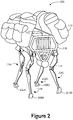
- FIG. 2 illustrates a perspective view of an example quadruped robot, according to an example implementation.
- the robotic device 200 may be configured to perform the procedures described herein during operation.
- the robotic device 200 includes legs 204A, 204B, 204C, and 204D connected to a body 208 of the robotic device 200 and may also include sensors configured to provide sensor data to a computing system of the robotic device 200.
- Each leg 204A, 204B, 204C, and 204D may include feet 206A, 206B, 206C, and 206D, respectively.
- Sensors may be incorporated within portions of the legs 204A, 204B, 204C, and 204D to detect pressure, position, velocity, acceleration, and orientation, among other measurements.
- the robotic device 200 is illustrated carrying objects 212 on the body 208.
- the robotic device 200 may include more or fewer components and may additionally include components not shown in Figure 2 .
- the robotic device 200 may be a physical representation of the robotic system 100 shown in Figure 1 or may be based on other configurations.
- the robotic device 200 includes a computing system that be made up of one or multiple computing devices configured to assist in various operations of the robotic device 200. These operations may include processing data and providing outputs based on the data to cause various changes to the physical state of the robotic device 200.
- the computing system may process information provided by various systems of the robotic device 200 (e.g., a sensor system) or from other sources (e.g., a user, another robotic device, a server) and may provide instructions to these systems to operate in response.
- the computing system may monitor systems of the robotic device 200 during operation, which may include monitoring for errors and/or monitoring regular operation, for example.
- the computing system may serve as a connection between the various systems of the robotic device 200, and may coordinate the operations of the systems together to enable the robotic device 200 to perform operations.
- the computing system may include multiple devices, processors, controllers, and/or other entities configured to control or assist in the operation of the robotic device. Additionally, the computing system may operate using various types of memory and/or other components.
- the robotic device 200 exists as a quadruped robotic device with four extendable legs 204A, 204B, 204C, and 204D. Although the robotic device 200 includes four legs 204A, 204B, 204C, and 204D in the illustration shown in Figure 2 , the robotic device 200 may include more or less legs within other examples. Further, the configuration, position, and/or structure of the legs 204A, 204B, 204C, and 204D may vary in example implementations.
- the legs 204A, 204B, 204C, and 204D enable the robotic device 200 to move and may be configured to operate in multiple degrees of freedom to enable different techniques of travel to be performed. In particular, the legs 204A, 204B, 204C, and 204D may enable the robotic device 200 to travel at various speeds through mechanically controlling the legs 204A, 204B, 204C, and 204D.
- Each robotic leg 204A, 204B, 204C, and 204D may include joints, such at joint 214, and actuators.
- the joints allow members of a robotic leg to move through a range of angular degrees in a number of degrees of freedom.
- an actuator may be extended or compressed in order facilitate moving a robotic leg to various positions.
- Certain joints may have limited ranges of motion (e.g. -120 degrees to 120 degrees).
- Some combinations of joints and members may allow a robotic leg to move its lateral position, longitudinal position, and/or vertical position.
- a gait is a pattern of movement of the limbs of animal, robotic device, or other mechanical structure.
- the robotic device 200 may navigate by operating the legs 204A, 204B, 204C, and 204D to perform various gaits.
- the robotic device 200 may use a variety gaits to travel within an environment, which may involve selecting a gait based on speed, terrain, the need to maneuver, and/or energy efficiency.
- the robotic device 200 may be configured to dynamically switch between gaits, which may enable the robotic device to change speeds or the mechanics of operating the legs 204A, 204B, 204C, and 204D.
- different types of robotic devices may use different gaits due to differences in design (e.g. the number of legs of the robotic device) that may prevent use of certain gaits.
- some gaits may have specific names (e.g., walk, trot, run, gallop, and bound), the distinctions between these gaits may be slight.
- the gaits may be classified based on footfall patterns, the patterns including locations on a surface for the placement of distal ends of the extendable legs (e.g., feet).
- gaits may also be classified based on mechanics.
- the robotic device 200 may include other mechanical apertures or appendages, which may be attached to the robotic device 200 at various positions.
- the robotic device 200 may include mechanical arms, grippers, wheels, or other features.
- the legs 204A, 204B, 204C, and 204D may have feet or other types of mechanical features (e.g. rubber feet to increase friction between the robotic device and a surface) that enables control upon various types of surfaces that the robotic device may encounter.
- the body 208 of the robotic device 200 connects to the legs 204A, 204B, 204C, and 204D and may house various components of the robotic device 200.
- the structure of the body 208 may vary within examples and may further depend on particular operations that a given robotic device may have been designed to perform. For example, a robotic device developed to carry heavy loads may have a wide body that enables placement of the loads. Similarly, a robotic device designed to reach high speeds may have a narrow, small body that does not have substantial weight.
- the body 208 as well as the legs 204A, 204B, 204C, and 204D may be developed using various types of materials, such as various metals or plastics.
- a robotic device may have a body with a different structure or made of other types of materials.
- the sensor(s) 210 of the robotic device 200 may include various types of sensors.
- the sensor(s) 210 may be placed at various positions on the robotic device.
- the robotic device 200 may include a sensory system that includes a camera, RADAR, LIDAR, a GPS transceiver, accelerometer(s), gyroscope(s), and/or other types of sensors.
- the sensor(s) may be configured to measure parameters of the environment of the robotic device 200 as well as monitor internal operations of systems of the robotic device 200.
- the robotic device 200 may include sensors to measure the orientation, position, velocity, or acceleration of each leg 204A, 204B, 204C, and 204D.
- sensor(s) 210 may be coupled to portions of the robotic legs 204A, 204B, 204C, and 204D.
- sensors may be configured to measure the angles of the joints of the robotic legs 204A, 204B, 204C, and 204D.
- the information or data output by the sensors may be provided to the control system 202.
- inertial measurement units IMUs may be mounted to sections of the robotic legs 204A, 204B, 204C, and 204D in order to determine the orientation of each member the robotic legs 204A, 204B, 204C, and 204D.
- sensors such as pressure transducers, may be coupled to the actuators of the robotic legs 204A, 204B, 204C, and 204D to measure the pressure inside the actuators and/or to measure the length that the actuator is extended or compressed.
- Other sensors may be included in addition to the previously mentioned sensors in order to measure aspects of the robotic device 200 from which angles of the joints of the robotic legs 204A, 204B, 204C, and 204D can be calculated.
- the actuators of the robotic legs 204A, 204B, 204C, and 204D may be controlled to apply varying amounts of force.
- a control system may control a particular robotic leg to apply a greater or lesser extent of force.
- an amount of force being applied by a given robotic leg may be measured using sensors coupled to the robotic leg, such as a force sensor or a load cell.
- the loads 212 carried by the robotic device 200 may represent various types of cargo that the robotic device 200 may transport.
- the loads 212 may also represent external batteries or other types of power sources (e.g., solar panels) that the robotic device 200 may utilize.
- the loads 212 represent an example use the robotic device 200 may be configured for. As such, the robotic device 200 may be configured to perform other operations as well.
- the robotic device 200 may also include various electrical components that may enable operation and communication between the mechanical features of the robotic device 200.
- the robotic device 200 may include one or more computing systems that include one or multiple processors configured to perform various functions, including processing inputs to provide outputs.
- the computing system may include additional components, such as various types of storage and a power source, etc.
- Control system 202 of robotic device 200 may cause the robotic device 200 to navigate an environment based on sensor data from the sensing system.
- the sensing system may include sensors of sensing system coupled to portions of the robotic device 200.
- the robotic device 200 may receive navigation commands by way of a communication system. For instance, the robotic device may receive a command to move forward at 5 kilometers per hour. The command may specify to walk forward for a particular distance, such as 100 meters. In an example, a command may specify one or more locations at which to place particular legs.
- the navigation commands may involve GPS coordinates.
- a command may instruct the robotic device to navigate to a particular position, which may be defined by particular GPS coordinates.
- the robotic device may then cause the locomotion system to move to the position while navigating physical features of the terrain identified by the control system (perhaps based on data from perception sensors).
- Another command may instruct the robotic device to follow a particular person, who may have with them a GPS enabled device that generates data indicating the position of the person.
- the data may be communicated to the robotic device that may then cause the locomotion system to follow the person while navigating physical features of the terrain identified by the control system.
- the computing system may communicate with other systems of the robotic device 200 via wired or wireless connections and may further be configured to communicate with one or multiple users of the robotic device.
- the computing system may receive an input from a user indicating that the user wants the robotic device to perform a particular gait in a given direction.
- the computing system may process the input, and may cause the systems of the robotic device to perform the requested gait.
- the robotic device's electrical components may include other type of electrical components, including but not limited to interface, wires, busses, and/or other communication links configured to enable systems of the robotic device to communicate.
- the robotic device 200 may communicate with one or multiple users and/or other robotic devices via various types of interfaces.
- the robotic device 200 may receive input from a user via a joystick or similar type of interface.
- the computing system may be configured to receive data indicative of the amount of force, the duration of force applied to the joystick, and other possible information, from a joystick interface.
- the robotic device 200 may receive inputs and communicate with a user via other types of interface, such as a mobile device or a microphone.
- the computing system of the robotic device 200 may be configured to process the various types of inputs that the robotic device 200 may receive.
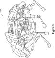
- Figure 3 illustrates another example quadruped robot, according to an example implementation.
- the robotic device 300 may correspond to the robotic system 100 shown in Figure 1 .
- the robotic device 300 serves as another possible implementation of a robotic device that may be configured to estimate the robotic device's orientation, yaw, pitch, and/or roll. Other example implementations of robotic devices may exist.
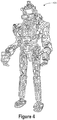
- Figure 4 illustrates an example of a biped robot according to another example implementation.
- the robotic device 400 may correspond to the robotic system 100 shown in Figure 1 .
- the robotic device 400 serves as a possible implementation of a robotic device that may be configured to estimate the robotic device's orientation, yaw, pitch, and/or roll. Other example implementations of robotic devices may exist.
- the robotic device 400 may include a number of articulated appendages, such as robotic legs and/or robotic arms.
- Each articulated appendage may include a number of members connected by joints that allow the articulated appendage to move through certain degrees of freedom.
- Each member of an articulated appendage may have properties describing aspects of the member, such as its weight, weight distribution, length, and/or shape, among other properties.
- each joint connecting the members of an articulated appendage may have known properties, such as the degrees of its range of motion the joint allows, the size of the joint, and the distance between members connected by the joint, among other properties.
- a given joint may be a joint allowing one degree of freedom (e.g.
- a degree of freedom may refer to the ability of a member connected to a joint to move about a particular translational or rotational axis.
- the robotic device 400 may also include sensors to measure the angles of the joints of its articulated appendages.
- the articulated appendages may include a number of actuators that can be controlled to extend and retract members of the articulated appendages.
- the angle of a joint may be determined based on the extent of protrusion or retraction of a given actuator.
- the joint angles may be inferred from position data of inertial measurement units (IMUs) mounted on the members of an articulated appendage.
- IMUs inertial measurement units
- the joint angles may be measured using rotary position sensors, such as rotary encoders.
- the joint angles may be measured using optical reflection techniques. Other joint angle measurement techniques may also be used.
- the robotic device 400 may be configured to send sensor data from the articulated appendages to a device coupled to the robotic device 400 such as a processing system, a computing system, or a control system.
- the robotic device 400 may include a memory, either included in a device on the robotic device 400 or as a standalone component, on which sensor data is stored. In some implementations, the sensor data is retained in the memory for a certain amount of time. In some cases, the stored sensor data may be processed or otherwise transformed for use by a control system on the robotic device 400. In some cases, the robotic device 400 may also transmit the sensor data over a wired or wireless connection to an external device.
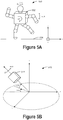
- Figures 5A and 5C illustrate stances of an example biped robot.
- the biped robot shown in Figures 5A and 5C may the same as or similar the robotic device 400 depicted in Figure 4 , the robotic device 300 depicted in Figure 3 , or the robotic device 200 depicted in Figure 2 .
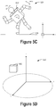
- Figures 5B and 5D depict simplified representations of the biped robot in Figures 5A and 5C , respectively.
- the simplified representations shown in Figures 5B and 5D are rigid body estimations of the biped robot's aggregate orientation from Figures 5A and 5C , respectively.
- Figures 5A and 5C illustrate axes representing the direction of the x-, y-, and z-axes.
- the circle with the dot in its center represents the x-axis pointing out of the front of the illustrations.
- Figures 5B and 5D illustrate a three-dimensional representations of axes that also have particular designations for the x-, y-, and z-axes.
- the axes in Figures 5B and 5D may be designated in other ways in various implementations.
- Figures 5A, 5B , 5C, and 5D include arrows depicting an amount of yaw rotation, pitch rotation, and roll rotation.
- the rotation amounts may be represented as degrees or radians.
- these arrows represent the amount of yaw rotation, pitch rotation, and roll rotation measured from sensors coupled to the base (i.e. the main body) of the biped robot (i.e. orientation of the base of the biped robot).
- the yaw, pitch, and roll arrows represent the aggregate amount of yaw rotation, pitch rotation, and roll rotation estimated by a processing system of the biped robot based on the orientation of the biped robot's base and the angles of the biped robot's joints.
- the arrows depicted in Figures 5A and 5C do not necessarily imply that there is an amount of yaw rotation, pitch rotation, or roll rotation.
- the amount of roll rotation of the biped robot in Figure 5A may be zero degrees.
- the arrows are depicted for explanatory purposes, and the amount of yaw, pitch, and roll rotation may be specified within particular sections of this application.
- the aggregate orientation and/or angular velocity of any other robotic device having any number of limbs may be estimated in accordance with operations of the present application.
- the aggregate orientation and/or angular velocity may be determined for robotic device 200 illustrated in Figure 2 and for the robotic device 300 illustrated in Figure 3 , among other robotic devices.
- FIG 5A illustrates a stance 500 of a biped robot 502, according to an example implementation.
- the biped robot 502 is standing on surface 504 with one leg.
- the biped robot 502 may be similar to robotic device 400 shown in Figure 4 , and may also include one or more components of robotic device 100 in Figure 1 .
- the body of the biped robot 502 is depicted as being parallel with surface 504, such that sensors coupled to the body of the biped robot 502 might indicate the roll angle of the body to be zero.
- the limbs of the biped robot 502 are extended such that a torque is applied to the biped robot 502.
- the biped robot 502 is depicted as being upright, the biped robot 502 depicted in Figure 5A would fall to the right if no balance control was applied to move the limbs.
- a control system that receives information from sensors coupled to the body of the biped robot 502 may determine that no control is required to maintain the biped robot's balance.
- a control system may react to angular velocity sensed after the biped robot begins to fall; however, reacting to changes in angular velocity may result in the control system providing drastic control measures to maintain the biped robot's balance.
- controlling the biped robot on the basis of changes to angular velocity is reactive, and may cause a control system to provide an otherwise unnecessary amount of control effort.
- the biped robot 502 may include a processing system thereon that is configured to estimate an aggregate orientation of the biped robot 502.
- the processing system may also calculate the rate of change of the aggregate orientation of the biped robot 502 to determine the angular velocity and/or the angular momentum of the biped robot 502.
- the processing system estimates the aggregate orientation of the biped robot 502 based on the angles of the joints of the biped robot's limbs and the measured orientation of the body of the biped robot 502.
- the aggregate orientation, angular velocity, and/or angular momentum of the biped robot 502 may be provided as inputs to a control system coupled to the biped robot.
- the control system may be configured to operate the biped robot with a particular behavior (i.e. stationary balancing, walking, running, etc.).
- the processing system may include a memory that stores a relationship between the joint angles of the robotic device and the extent to which the joint angles of the robotic device affect the orientation and/or angular velocity of the base of the robotic device.
- Each limb of the biped robot 502 includes members and joints, allowing the limbs to be positioned in a variety of ways. As previously described, the positioning of the limbs may be achieved through actuation of actuators coupled to members of the limbs of the biped robot 502. As a given limb moves through its range of motion, the limb's center of mass may be positioned at a variety of locations having varying distances from the center of mass of the body of the biped robot 502.
- the mass of a limb of the biped robot 502 extended away from the biped robot's body may introduce a torque on the body of the biped robot 502 as a result of a gravitational force on the extended limb.
- a relationship between the joint angles and the motion of the body of the biped robot 502 may be determined.
- the processing system may then apply the effects of the joint angles to the measured orientation of the body of the biped robot 502 to determine the biped robot's aggregate orientation.
- the processing system performs a time differentiation on the aggregate orientation in order to estimate the biped robot's angular velocity.
- the processing system may also determined an estimated angular momentum of the biped robot 502 based on the estimated angular velocity.
- the angular velocity and/or the angular momentum may be used to predict the aggregate orientation of the biped robot 502 at a future time.
- a control system may proactively provide balance control before the body of the biped robot 502 is moving at a significant angular velocity. By anticipating the aggregate orientation of the biped robot 502 before the biped robot 502 rotates to that orientation, unstable orientations may be preemptively identified, greatly reducing the extent of control effort required to balance the biped robot 502 compared to a reactive control system.
- a quadruped robot such as robotic device 200 in Figure 2 or robotic device 300 in Figure 3 may be travelling at a great enough velocity that no legs are in contact with the ground at certain times. In these cases, predicting the aggregate orientation of the quadruped robot while in the quadruped robot is in mid-air may be useful in determining how to orient the front legs of the quadruped robot before making contact with the ground.
- a robotic device may include a flexible member coupled to the body of the robotic device that allows the body to bend and/or rotate. Sensors may measure the angle of the rotating sections of the flexible member and provide the angle measurements as input to the processing system. The processing system may consider those angle measurements, along with other angle measurements and a measurement of the orientation of a portion of the body in determining the aggregate orientation of the robotic device.
- the body of the biped robot 502 depicted in Figure 5A has a yaw angle of zero degrees, a pitch angle of zero degrees, and a roll angle of zero degrees.
- the limbs of the biped robot 502 are oriented such that the biped robot is unstable. Thus, as time progresses, the biped robot 502 would tip over if no balance control was provided to the limbs.
- FIG 5B illustrates a simplified representation 510 of biped robot 502 shown in Figure 5A .
- the processing system of biped robot 502 may receive the zero degree measurements of the yaw, pitch, and roll angles, along with the angles of the joints of the biped robot 502. The processing system may then determine the aggregate orientation of the biped robot 502. Although the yaw, pitch, and roll angles of the body of the biped robot 502 were zero degrees, the aggregate orientation of the biped robot 502 may have non-zero values.
- the simplified representation 512 of the biped robot 502 has non-zero yaw, pitch, and roll angles.
- the simplified representation 512 of the biped robot 502 is oriented with respect to a reference frame 510, which may be a surface or the ground.
- at least one of the non-zero yaw, pitch, and roll angles may indicate instability in the balance of the biped robot 502.
- a non-zero roll angle may, in some cases, be indicative of a torque applied to the body of the biped robot 502 resulting from one or more limbs being extended to one side of the biped robot 502.
- the aggregate orientation indicates instability that would increase the angular velocity of the biped robot 502 over time.
- the estimated aggregate orientation may be provided to a control system of the biped robot 502, which may subsequently control at least one of the limbs of the biped robot 502 to balance the biped robot 502.
- the lifted leg of the biped robot 502 in Figure 5A may be placed on the ground, thereby changing the angle of one or more joints of the lifted leg.
- the aggregate orientation estimated by the processing system may indicate that the biped robot 502 is becoming more stable. For instance, the changing joint angles caused by extending the leg to touch the surface 504 may decrease the aggregate roll angle.
- control system of the biped robot 502 is configured to maintain the translational velocity of the biped robot 502 at particular pace (e.g. walking pace or a running pace).
- a robotic device may have a relationship that correlates the positions of its joint angles with the aggregate orientation of the robotic device.
- the robotic device may have two legs and one arm, where the one arm has one joint connecting a member attached to the robotic device's body to another member.
- the relationship may dictate that, when the joint has an angle that is between 0 and 90 degrees, the arm does not introduce enough torque to cause the robot to tip over.
- the relationship may also dictate that, when the joint has an angle between 90 and 180 degrees, the arm produces enough torque on the robotic device's body, causing the robotic device to angularly accelerate and eventually tip over. Any combination of joint angle ranges may be correlated to a torque produced on the body of the robotic device in various implementations.
- a robotic device may be running and thus does not have any contact with the ground at certain points in time.
- the robotic device's body may oscillate while running, such that a control device considering only the orientation measurement of the robotic device's body may, at certain points in time, determine that the robotic device is unstable and thus requires a control effort to maintain balance.
- a relationship between the joint angles of the legs of the robotic device and the orientation of the body of the robotic device may indicate that the aggregate orientation of the robotic device has a far less severe oscillation compared to the body orientation of the robotic device.
- a control system of the present disclosure reduces unnecessary control effort that may otherwise have been exerted.
- Figure 5C illustrates a stance 520 of a biped robot 522, according to an example implementation.
- biped robot 522 is standing on surface 524 with one leg.
- the body of the biped robot 522 is depicted as being tilted, such that sensors coupled to the body of the biped robot 522 might indicate the roll angle of the body to be non-zero.
- the biped robot 522 may be the same as or similar to robotic device 400 shown in Figure 4 , and may also include one or more components of robotic device 100 in Figure 1 .
- the limbs of biped robot 522 are extended such that the biped robot 522 is balanced. Unlike the biped robot 502 in Figure 5A , the biped robot 522 is stable and does not require control of the limbs to maintain balance. The limbs of the biped robot 522 are extended in such a way that no torque is applied on the body of the biped robot 522.
- the biped robot 522 may include a processing system thereon that is configured to estimate an aggregate orientation of the biped robot 522.
- the processing system may receive the angles of the joints of the biped robot 522 and the measured orientation of the body to determine the biped robot's aggregate orientation.
- the processing system determines from the aggregate orientation that the biped robot 522 is stable.
- the processing system may also perform a time differentiation of the aggregate orientation and determine that the angular velocity of the biped robot 522 is not changing.
- the body of the biped robot 522 in Figure 5C has a yaw angle of zero degrees, a pitch angle of zero degrees, and a non-zero roll angle.
- Figure 5D illustrates a simplified representation 532 of a biped robot 522, according to an example implementation.
- the simplified representation 532 of the biped robot 502 is oriented with respect to a reference frame 530, which may be a surface or the ground.
- the processing system of the biped robot 522 may receive measurements of the orientation of the body of the biped robot 522 indicating zero-degree yaw and pitch angles and a non-zero roll angle.
- the processing system of the biped robot 522 may also receive measurements of the angles of the joints of the biped robot 522. Then, the processing system may estimate the aggregate orientation of the biped robot 522 in the same or similar manner as previously described. Although the received roll angle of the biped robot's body is non-zero, the aggregate orientation of the biped robot 522 indicates that the biped robot 522 has a zero degree roll angle.
- the estimated aggregate orientation may be provided to a control system of the biped robot 522.
- the control system may determine that the biped robot 522 is stable and does not require control to maintain balance of the biped robot 522.
- the aggregate orientation may indicate that the aggregate roll angle of the biped robot 522 is a very small non-zero amount.
- the processing system may predict that the aggregate orientation of the biped robot 522 is accelerating about the roll axis.
- the control system may control the limbs of the biped robot 522 to maintain balance of the biped robot 522.
- the control system may vary the force applied to the ground by the leg of the biped robot 522 in order to maintain balance.
- the processing system determines a path that indicates an expected trajectory of the robot based on the estimated aggregate orientation, among other measurements (e.g . the velocity and direction of the velocity of the robotic device). This may involve computing the expected locations of the robotic device based on its estimated aggregate orientation for a threshold amount of time. For example, the determined path may indicate the expected trajectory for a one minute period of time in the future.
- the processing system may also determine whether an object is present within the determined path. This may involve the processing system receiving images from an image-capture system coupled to the robotic device and performing object detection techniques to identify any possible objects. In some cases, an object may be detected if it is above a certain threshold size.
- the processing system may modify or otherwise alter the path of the robot so that its trajectory avoids a collision with the object.
- the processing system may accomplish this by providing instructions to change the orientation and/or velocity (in the x-direction, y-direction, and/or z-direction) of the robotic device.
- the processing system may calculate the expected trajectory of the robotic device to ensure that the robotic device avoids colliding with the detected object.
- the processing system may provide instructions to the robotic device to stop the robotic device from hitting the object.
- the processing system may receive a desired trajectory for the robotic device to travel along.
- the processing system may then, based on the desired trajectory and the estimated aggregate orientation of the robotic device, determine a manner in which to operate the robotic device that causes it to travel along this desired trajectory. This may include providing instructions to modify the robotic device's orientation and/or velocity (in the x-direction, y-direction, and/or the z-direction).
- Figure 6 is a flowchart 600, according to an example implementation.
- the operations in the flowchart could, for example, be performed by the robotic device 100 in Figure 1 , the robotic device 200 in Figure 2 , the robotic device 300 in Figure 3 , the robotic device 400 in Figure 4 , or any combination of components from robotic device 100, robotic device 200, robotic device 300, and/or robotic device 400.
- Figure 6 may include one or more operations, or procedures as illustrated by one or more of blocks 602, 604, 606, 608, and 610. Although the blocks are illustrated in a sequential order, these blocks may in some instances be performed in parallel, and/or in a different order than those described herein. Also, the various blocks may be combined into fewer blocks, divided into additional blocks, and/or removed based upon the desired implementation.
- each block may represent a module, a segment, or a portion of program code, which includes one or more instructions executable by a processor for implementing specific logical operations or steps in this process.
- each block may represent a portion of program code that performs and/or modifies an operation of a robotic device.
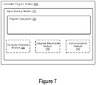
- the program code may be stored on any type of computer-readable medium, for example, such as a storage device including a disk or hard drive.
- the computer-readable medium may include a non-transitory computer-readable medium, for example, such as computer-readable media that stores data for short periods of time like register memory, processor cache and random access memory (RAM).
- the computer-readable medium may also include other non-transitory media, such as secondary or persistent long term storage, like read only memory (ROM), optical or magnetic disks, compact-disc read only memory (CD-ROM), for example.
- the computer-readable media may also be any other volatile or non-volatile storage system.
- the computer-readable medium may be considered a computer-readable storage medium, a tangible storage device, or other article of manufacture, for example.
- the program code (or data for the code) may also be stored or provided on other media including communication media. For instance, the commands may be received on a wireless communication media.
- each block may represent circuitry that is arranged to perform the specific logical operations.
- Operations of Figure 6 may be fully performed by a control device or by the processor, or may be distributed across multiple control devices.
- the control device may receive information from sensors of a robotic device, or the control device may receive the information from a processor that collects the information.
- the control system might further communicate with a remote control system (e.g ., a control device on another robotic device) to receive information from sensors of other devices, for example.
- a remote control system e.g ., a control device on another robotic device
- the operations of blocks 602, 604, 606, 608, and 610 are described as being performed by a control device; however, other devices as described above may carry out the operations.
- a processing system receives a first plurality of measurements indicative of respective joint angles corresponding to a plurality of sensors connected to a robot.
- the joint angle measurements received may be analog electrical signals representing the joint angles.
- the sensors include circuitry to convert the analog electrical signals to digital electrical signals representing the joint angles.
- a given sensor may detect relative changes in the joint angle, and the processing system may keep track of the position of the joints by measuring the changes in the joint angle over time.
- the joint angles may be represented in degrees or in radians, depending on the particular implementation.
- the sensors may transmit the joint angles to the processing system via a wired connection or a wireless connection.
- the processing system receives an orientation measurement indicative of an orientation of the body of the robot.
- the orientation of the body of the robotic device may be measured by one or more sensors, such as accelerometers, gyroscopes, magnetometers, and/or inertial measurement units (IMUs), among other sensors.
- the sensors may measure acceleration of the body of the robotic device and/or rotational angles such as pitch, roll, and yaw of the body of the robot.
- the sensors may provide the acceleration and/or rotational angles to the processing system, and the processing system may determine at least one of the velocity, position, orientation, and the angular velocity of the body of the robot.
- the sensors may include thereon circuitry to determine at least one of the velocity, position, orientation and/or angular velocity of the body of the robot, and may then provide those measurements to the processing system.
- the body of the robotic device may be any portion of the robotic device to which robotic limbs are connected.
- the robotic limbs are connected to the body of the robotic device through rotatable joints.
- the processing system determines a relationship between the first plurality of measurements and the orientation measurement based on the properties associated with the jointed limbs of the robot.
- the relationship may be the same as or similar to relationships previously described.
- the relationship may be stored on a memory coupled to the robot.
- the robotic device may include a computing device that is configured to execute program instructions stored on the memory. In some implementations, the relationship may be integrated into the program instructions.
- the relationship may be a mathematical formula or algorithm that can be used to determine the robot's aggregate orientation from the orientation measurement and joint angle measurements.
- the processing system and/or computing device of the robotic device may perform the calculation of the mathematical formula or execute the algorithm in order to determine the robot's aggregate orientation.
- this relationship may be integrated as a part of a control system implemented on a control device, such as a field-programmable gate array (FPGA).
- FPGA field-programmable gate array
- the relationship may be updated or otherwise modified.
- instructions to update or modify the relationship may be received at a communication link of the robot.
- multiple relationships may be used to determine the aggregate orientation of the robot, and the robotic device may receive instructions to add, remove, update, or modify one or more these relationships.
- the processing system estimates an orientation of the robotic device based on the first plurality of measurements, the orientation measurement, and the determined relationship.
- the estimated orientation of the robotic device may be the same as or similar to the aggregate orientation of the robotic device as previously described.
- the estimated orientation may be determined by performing mathematical or algorithmic operations on the first plurality of measurements and the orientation measurements in accordance with the received relationship.
- the estimated orientation may be stored on a memory of the robot.
- the estimated orientation is transmitted to an external computing device either over a wired connection or a wireless connection.
- the estimated orientation may be provided to other devices or systems of the robot, such as a control system.
- the processing system provides instructions to control at least one jointed limb of the robotic device based on the estimated orientation of the robot.
- the instructions may correspond to maneuvering one or more of the limbs of the robot.
- an instruction may cause a limb of the robotic device to move to a specific location and have a specific orientation.
- An instruction may also specify the manner in which to move the limb (e.g. how quickly the move the limb to the specific location).
- An instruction may further specify the amount of force that a particular limb applied to the ground or other surface.
- the instructions are analog signals that control actuators on the limbs of the robot.
- the actuators may be configured to receive digital signals, and the instructions may be digital signals provided to one or more actuators to control the limbs of the robot.
- Figure 7 illustrates an example computer-readable medium configured according to at least some implementation described herein.
- the example system can include one or more processors, one or more forms of memory, one or more input devices/interfaces, one or more output devices/interfaces, and machine readable instructions that when executed by the one or more processors cause a robotic device to carry out the various functions tasks, capabilities, etc., described above.
- Figure 7 is a schematic illustrating a conceptual partial view of a computer program product that includes a computer program for executing a computer process on a computing device, arranged according to at least some implementations disclosed herein.
- the example computer program product 700 is provided using a signal bearing medium 702.
- the signal bearing medium 702 may include one or more program instructions 704 that, when executed by one or more processors may provide functionality or portions of the functionality described above with respect to Figures 1-6 .
- the signal bearing medium 702 can be a computer-readable medium 706, such as, but not limited to, a hard disk drive, a Compact Disc (CD), a Digital Video Disk (DVD), a digital tape, memory, etc.
- the signal bearing medium 702 can be a computer recordable medium 708, such as, but not limited to, memory, read/write (R/W) CDs, R/W DVDs, etc.
- the signal bearing medium 702 can be a communication mediums 710 (e.g., a fiber optic cable, a waveguide, a wired communications link, etc.).
- the signal bearing medium 702 can be conveyed by a wireless form of the communications medium 710.
- the one or more program instructions 704 can be, for example, computer executable and/or logic implemented instructions.
- a computing device is configured to provide various operations, functions, or actions in response to the program instructions 704 conveyed to the computing device by the computer readable medium 706, the computer recordable medium 708, and/or the communications medium 710.
- the computing device can be an external device in communication with a device coupled to the robotic device.
- the computer readable medium 706 can also be distributed among multiple data storage elements, which could be remotely located from each other.
- the computing device that executes some or all of the stored instructions could be an external computer, or a mobile computing platform, such as a smartphone, tablet device, personal computer, or a wearable device, among others.
- the computing device that executes some or all of the stored instructions could be a remotely located computer system, such as a server.
- the computer program product 700 can implement operations discussed in reference to Figure 6 .
Landscapes
- Engineering & Computer Science (AREA)
- Mechanical Engineering (AREA)
- Robotics (AREA)
- Chemical & Material Sciences (AREA)
- Combustion & Propulsion (AREA)
- Transportation (AREA)
- Manipulator (AREA)
- Rehabilitation Tools (AREA)
Claims (19)
- Procédé comprenant :la réception, par un robot (200), d'une première pluralité de mesures indicatrices d'angles d'articulation respectifs correspondant à une pluralité de capteurs (210) connectés au robot, dans lequel le robot comprend un corps (208) et une pluralité de membres articulés (204A-D) connectés au corps, et dans lequel les membres articulés sont associés à des propriétés respectives (602) ;la réception d'une mesure d'orientation de corps indicatrice d'une orientation du corps du robot (604) ;la détermination d'une relation entre les angles d'articulation et l'orientation du corps sur la base des propriétés respectives associées aux membres articulés du robot (606) ;l'estimation d'une orientation agrégée du robot sur la base de la première pluralité de mesures, la mesure d'orientation du corps, et la relation déterminée en appliquant des effets des angles d'articulations à l'orientation mesurée du corps (608) ;la détermination d'une vitesse angulaire et/ou d'un moment cinétique du robot sur la base d'un taux de changement de l'orientation agrégée estimée du robot ;la prédiction d'une orientation agrégée du robot à un moment futur sur la base de la vitesse angulaire déterminée et/ou du moment cinétique ;l'identification, sur la base de l'orientation agrégée prédite, qu'il est prédit que le robot se trouve dans une orientation instable à un moment futur ;et en réponse à la détermination qu'à un moment futur, il est prédit que le robot se trouve dans l'orientation instable, sur la base de l'orientation agrégée prédite du robot, la fourniture d'instructions pour commander à au moins un membre articulé du robot de maintenir un équilibre du robot (610).
- Procédé selon la revendication 1, dans lequel la relation déterminée comprend une première relation et une deuxième relation, et dans lequel le procédé comprend en outre :la détermination d'un mode de fonctionnement particulier du robot (200) correspondant à l'un ou plusieurs de la première pluralité de mesures se trouvant dans une ou plusieurs plages de fonctionnement respectives ;et la détermination que la deuxième relation entre les angles d'articulation et l'orientation du corps associée au mode de fonctionnement particulier sur la base (i) des propriétés respectives associées aux membres articulés (204A-D) du robot et (ii) du mode de fonctionnement particulier déterminé du robot.
- Procédé selon la revendication 2, dans lequel l'estimation de l'orientation du robot (200) comprend :
sur la base de la détermination que le robot fonctionne dans le mode de fonctionnement particulier, l'estimation de l'orientation du robot sur la base de la première pluralité de mesures, la mesure d'orientation du corps et la deuxième relation. - Procédé selon l'une quelconque des revendications précédentes, dans lequel la fourniture d'instructions pour commander au moins un membre articulé (204A-D) du robot (200) comprend :sur la base de l'orientation agrégée estimée, la détermination d'un degré de force selon lequel placer un membre articulé particulier du robot sur une surface afin de maintenir un équilibre du robot ;et la fourniture d'instructions pour placer le membre articulé particulier du robot sur la surface en utilisant le degré de force déterminé.
- Procédé selon l'une quelconque des revendications précédentes, dans lequel la fourniture d'instructions pour commander au moins un membre articulé (204A-D) du robot (200) comprend :sur la base de l'orientation agrégée estimée, la détermination d'un emplacement où déplacer un membre articulé particulier du robot afin de maintenir un équilibre du robot ;et la fourniture d'instructions pour déplacer le membre articulé particulier du robot à l'emplacement déterminé.
- Procédé selon l'une quelconque des revendications précédentes, comprenant en outre :
la fourniture de l'orientation agrégée estimée du robot (200) à un système de commande (202), dans lequel le système de commande est configuré pour maintenir un équilibre du robot. - Procédé selon l'une quelconque des revendications précédentes, comprenant en outre :la détermination d'un chemin indicateur d'une trajectoire prévue du robot (200) sur la base de l'orientation agrégée estimée ;la détermination qu'un objet est présent sur le chemin déterminé ; et sur la base de la détermination que l'objet est présent sur le chemin déterminé, la fourniture d'instructions pour commander à au moins un membre (204A-D) du robot d'éviter une collision avec l'objet.
- Procédé selon l'une quelconque des revendications précédentes, comprenant en outre :
l'estimation d'une vitesse angulaire du robot (200) sur la base de l'orientation agrégée estimée du robot, dans lequel les instructions pour commander à l'au moins un membre articulé (204A-D) du robot sont en outre basées sur la vitesse angulaire estimée déterminée. - Procédé selon la revendication 8, dans lequel les instructions fournies sont des premières instructions, et dans lequel le procédé comprend en outre :la réception d'une deuxième pluralité de mesures indicatrices de forces externes exercées sur le robot (200) ;sur la base de la deuxième pluralité reçue de mesures et de la vitesse angulaire estimée du robot, la détermination d'un composant de la vitesse angulaire estimée induit par les forces externes exercées sur le robot ;et la fourniture de deuxièmes instructions pour commander au moins un membre articulé (204AD) du robot sur la base du composant déterminé de la vitesse angulaire estimée induit par les forces externes exercées sur le robot.
- Procédé selon l'une quelconque des revendications précédentes, dans lequel les instructions fournies sont des premières instructions, et dans lequel le procédé comprend en outre :
la fourniture d'un chemin indicateur d'une trajectoire souhaitée du robot (200) ; et sur la base du chemin fourni et de l'orientation agrégée estimée du robot, la fourniture de deuxièmes instructions pour commander à au moins un membre articulé (204A-D) du robot de manoeuvrer le robot pour se déplacer le long du chemin fourni. - Procédé selon l'une quelconque des revendications précédentes, dans lequel les instructions fournies sont des premières instructions, et dans lequel le procédé comprend en outre :la détermination si une position du robot (200) est stable sur la base de l'orientation agrégée estimée ; etsur la base de la détermination que la position du robot n'est pas stable, la fourniture de deuxièmes instructions pour commander à au moins un membre articulé (204A-D) du robot d'ajuster la position du robot.
- Procédé selon l'une quelconque des revendications précédentes, dans lequel les instructions fournies sont des premières instructions, et dans lequel le procédé comprend en outre :la réception d'une deuxième pluralité de mesures indicatrices de forces externes exercées sur le robot (200) ;la détermination d'une vitesse angulaire estimée du robot sur la base de l'orientation agrégée estimée et du robot ;la détermination d'un composant de la vitesse angulaire estimée induit par des mouvements des membres articulés du robot ; etla fourniture de deuxièmes instructions pour commander au moins un membre articulé (204A-D) du robot sur la base du composant déterminé de la vitesse angulaire estimée induit par des mouvements des membres articulés du robot.
- Procédé selon l'une quelconque des revendications précédentes, comprenant en outre : la détermination si un objet se trouve devant le robot (200) ; et
la fourniture d'instructions pour arrêter le robot en réponse à la détermination que l'objet se trouve devant le robot. - Procédé selon l'une quelconque des revendications précédentes, comprenant en outre :la détermination si un objet se trouve dans la portée d'un membre articulé particulier (204A-D) du robot (200) ; etla fourniture d'instructions pour limiter l'angle selon lequel le membre articulé particulier peut se déplacer pour éviter d'entrer en contact avec l'objet.
- Procédé selon l'une quelconque des revendications précédentes, dans lequel les instructions fournies sont des premières instructions, et dans lequel le robot (200) est en l'air au-dessus d'une surface, et dans lequel le procédé comprend en outre :la détermination d'un angle selon lequel ajuster un membre articulé donné (204A-D) parmi la pluralité de membres articulés sur la base de l'orientation agrégée estimée afin d'équilibrer le robot quand le membre articulé donné atterrit sur la surface ; etla fourniture de deuxièmes instructions pour ajuster le membre articulé donné à l'angle déterminé.
- Procédé selon l'une quelconque des revendications précédentes, comprenant en outre :la réception d'une deuxième pluralité de mesures indicatrices de forces externes exercées sur le robot (200) ;la détermination d'un moment cinétique mesuré du robot sur la base de la deuxième pluralité de mesures, au moins l'une de la première pluralité de mesures, et la mesure d'orientation du corps,dans lequel le moment cinétique mesuré inclut du bruit ayant une première amplitude moyenne ;l'estimation d'une vitesse angulaire du robot sur la base de l'orientation agrégée estimée du robot ;la détermination d'un moment cinétique estimé sur la base du moment cinétique mesuré et de la vitesse angulaire estimée en utilisant un observateur d'état basé sur une rétroaction, dans lequel le moment cinétique mesuré inclut du bruit ayant une deuxième amplitude moyenne, dans lequel la deuxième amplitude moyenne est inférieure à la première amplitude moyenne.
- Procédé selon l'une quelconque des revendications précédentes, dans lequel les propriétés respective associées aux membres articulés (204A-D) incluent une masse de chaque membre articulé et une forme de chaque membre articulé, et dans lequel la relation déterminée indique en outre une relation entre un couple produit à partir du déplacement d'un membre articulé donné et un couple appliqué au corps (208) du robot (200).
- Robot (200) comprenant : un corps (208) ;
une pluralité de membres articulés (204A-D) connectés au corps, dans lequel les membres articulés sont associés à des propriétés respectives ;
une première pluralité de capteurs (210) configurés pour fournir une première pluralité de mesures indicatrices d'angles d'articulation respectifs des membres articulés ;
un deuxième capteur configuré pour fournir une mesure d'orientation du corps indicatrice d'une orientation du corps du robot, dans lequel le deuxième capteur est couplé au corps ;
un système de traitement et un système de commande (202) configuré pour exécuter le procédé selon l'une quelconque des revendications précédentes. - Programme informatique (700) comprenant des instructions, lesquelles une fois exécutées par au moins un processeur, amènent un robot (200) à exécuter le procédé selon l'une quelconque des revendications 1 à 17.
Priority Applications (1)
| Application Number | Priority Date | Filing Date | Title |
|---|---|---|---|
| EP19155331.2A EP3498434A1 (fr) | 2014-08-25 | 2015-08-14 | Tangage et roulis naturels |
Applications Claiming Priority (4)
| Application Number | Priority Date | Filing Date | Title |
|---|---|---|---|
| US201462041281P | 2014-08-25 | 2014-08-25 | |
| US14/586,519 US9517561B2 (en) | 2014-08-25 | 2014-12-30 | Natural pitch and roll |
| US14/659,012 US9662792B2 (en) | 2014-08-25 | 2015-03-16 | Natural pitch and roll |
| PCT/US2015/045253 WO2016032773A2 (fr) | 2014-08-25 | 2015-08-14 | Tangage et roulis naturels |
Related Child Applications (2)
| Application Number | Title | Priority Date | Filing Date |
|---|---|---|---|
| EP19155331.2A Division-Into EP3498434A1 (fr) | 2014-08-25 | 2015-08-14 | Tangage et roulis naturels |
| EP19155331.2A Division EP3498434A1 (fr) | 2014-08-25 | 2015-08-14 | Tangage et roulis naturels |
Publications (2)
| Publication Number | Publication Date |
|---|---|
| EP3186041A2 EP3186041A2 (fr) | 2017-07-05 |
| EP3186041B1 true EP3186041B1 (fr) | 2019-04-03 |
Family
ID=55347481
Family Applications (2)
| Application Number | Title | Priority Date | Filing Date |
|---|---|---|---|
| EP15754383.6A Active EP3186041B1 (fr) | 2014-08-25 | 2015-08-14 | Tangage et roulis naturels |
| EP19155331.2A Pending EP3498434A1 (fr) | 2014-08-25 | 2015-08-14 | Tangage et roulis naturels |
Family Applications After (1)
| Application Number | Title | Priority Date | Filing Date |
|---|---|---|---|
| EP19155331.2A Pending EP3498434A1 (fr) | 2014-08-25 | 2015-08-14 | Tangage et roulis naturels |
Country Status (5)
| Country | Link |
|---|---|
| US (6) | US9517561B2 (fr) |
| EP (2) | EP3186041B1 (fr) |
| JP (4) | JP6483730B2 (fr) |
| CN (2) | CN106660206B (fr) |
| WO (1) | WO2016032773A2 (fr) |
Cited By (1)
| Publication number | Priority date | Publication date | Assignee | Title |
|---|---|---|---|---|
| US20230008096A1 (en) * | 2014-08-25 | 2023-01-12 | Boston Dynamics, Inc. | Natural pitch and roll |
Families Citing this family (25)
| Publication number | Priority date | Publication date | Assignee | Title |
|---|---|---|---|---|
| US20150168953A1 (en) * | 2013-12-13 | 2015-06-18 | Itrack Llc | Autonomous self-leveling vehicle |
| US11093590B2 (en) * | 2015-08-31 | 2021-08-17 | Avaya Inc. | Selection of robot operation mode from determined compliance with a security criteria |
| US10493617B1 (en) * | 2016-10-21 | 2019-12-03 | X Development Llc | Robot control |
| US10351189B2 (en) * | 2016-12-13 | 2019-07-16 | Boston Dynamics, Inc. | Whole body manipulation on a legged robot using dynamic balance |
| US10766140B2 (en) * | 2017-04-13 | 2020-09-08 | Battelle Memorial Institute | Teach mode collision avoidance system and method for industrial robotic manipulators |
| JPWO2019035362A1 (ja) * | 2017-08-18 | 2019-11-07 | 三菱電機株式会社 | ロボット制御装置およびこれを用いたロボットシステム |
| WO2019123769A1 (fr) * | 2017-12-19 | 2019-06-27 | ソニー株式会社 | Ensemble membre et robot |
| US10802508B2 (en) * | 2018-02-22 | 2020-10-13 | Boston Dynamics, Inc. | Mobile robot |
| US10800049B2 (en) * | 2018-02-22 | 2020-10-13 | Boston Dynamics, Inc. | Maneuvering mobile robots |
| CN108638095A (zh) * | 2018-04-02 | 2018-10-12 | 深圳小趴智能科技有限公司 | 一种机器人运动控制装置及其操作方法 |
| WO2020107279A1 (fr) * | 2018-11-28 | 2020-06-04 | 深圳市优必选科技有限公司 | Robot bipède et procédé de déplacement associé, appareil et support d'informations |
| CN111377004B (zh) * | 2018-12-28 | 2021-11-16 | 深圳市优必选科技有限公司 | 一种双足机器人步态控制方法以及双足机器人 |
| US11241982B2 (en) * | 2019-06-28 | 2022-02-08 | Honda Motor Co., Ltd. | Walking infant seat |
| CN110524561B (zh) * | 2019-09-27 | 2024-03-26 | 长沙紫宸科技开发有限公司 | 一种多功能仿人多足机器人 |
| GB2588629B (en) * | 2019-10-29 | 2024-01-03 | Cmr Surgical Ltd | Robotic joint control |
| CN111086001B (zh) * | 2019-12-25 | 2021-09-14 | 广东省智能制造研究所 | 一种足式机器人多模态感知的状态估计方法及系统 |
| CN111216126B (zh) * | 2019-12-27 | 2021-08-31 | 广东省智能制造研究所 | 基于多模态感知的足式机器人运动行为识别方法及系统 |
| CN112025706B (zh) * | 2020-08-26 | 2022-01-04 | 北京市商汤科技开发有限公司 | 机器人的状态确定方法及装置、机器人及存储介质 |
| EP4208316A4 (fr) * | 2020-09-01 | 2024-04-03 | Ceva Tech Inc | Déplacement à l'estime de robots plans avec un flux optique, codeur de roue et unité de mesure inertielle |
| CN112256047B (zh) * | 2020-09-30 | 2023-04-11 | 江苏集萃智能制造技术研究所有限公司 | 一种基于四元数的四足姿态控制策略 |
| US20220193899A1 (en) * | 2020-12-22 | 2022-06-23 | Ubtech Robotics Corp Ltd | Pose control method, robot and computer-readable storage medium |
| CN116395054A (zh) * | 2021-02-04 | 2023-07-07 | 深圳逐际动力科技有限公司 | 可变形态的腿部结构及机器人 |
| JP7156445B1 (ja) | 2021-05-18 | 2022-10-19 | 三菱電機株式会社 | 携帯端末、歩行ロボット、プログラム、および位置演算支援方法 |
| CN113997282B (zh) * | 2021-10-13 | 2022-11-25 | 杭州景业智能科技股份有限公司 | 机械臂控制方法、装置、电子装置和存储介质 |
| CN114911164B (zh) * | 2022-05-07 | 2023-05-02 | 北京理工大学 | 一种仿鼠四足机器人跳跃动作的开环控制方法及系统 |
Citations (1)
| Publication number | Priority date | Publication date | Assignee | Title |
|---|---|---|---|---|
| US20120316683A1 (en) * | 2011-06-10 | 2012-12-13 | Samsung Electronics Co., Ltd. | Balance control apparatus of robot and control method thereof |
Family Cites Families (136)
| Publication number | Priority date | Publication date | Assignee | Title |
|---|---|---|---|---|
| GB8906541D0 (en) | 1989-03-21 | 1989-05-04 | Portsmouth Tech Consult | Robot devices |
| JP2819353B2 (ja) * | 1990-09-28 | 1998-10-30 | 本田技研工業株式会社 | 脚式移動ロボットの歩行制御装置 |
| JP2997037B2 (ja) * | 1990-11-30 | 2000-01-11 | 本田技研工業株式会社 | 脚式移動ロボットの歩行制御装置 |
| JPH06170757A (ja) * | 1992-04-28 | 1994-06-21 | Honda Motor Co Ltd | リンク式移動ロボットの制御装置 |
| DE69725764T2 (de) * | 1996-07-25 | 2004-08-05 | Honda Giken Kogyo K.K. | Vorrichtung zur nachbildung des ganges für einen zweibeinigen robotor |
| US5929585A (en) * | 1996-11-19 | 1999-07-27 | Sony Corporation | Robot system and its control method |
| JP3956414B2 (ja) * | 1996-11-19 | 2007-08-08 | ソニー株式会社 | ロボット装置及びロボット装置の制御方法 |
| EP0965416B1 (fr) | 1996-12-19 | 2005-12-07 | Honda Giken Kogyo Kabushiki Kaisha | Controleur d'attitude de robot mobile sur jambes |
| JP3655056B2 (ja) * | 1997-08-04 | 2005-06-02 | 本田技研工業株式会社 | 脚式移動ロボットの制御装置 |
| JP2000236783A (ja) * | 1999-02-18 | 2000-09-05 | Mamiya Op Co Ltd | 釣 竿 |
| US6594552B1 (en) | 1999-04-07 | 2003-07-15 | Intuitive Surgical, Inc. | Grip strength with tactile feedback for robotic surgery |
| JP2001322079A (ja) | 2000-05-15 | 2001-11-20 | Sony Corp | 脚式移動ロボット及びその動作教示方法 |
| EP1332840B1 (fr) * | 2000-09-29 | 2009-11-04 | Honda Giken Kogyo Kabushiki Kaisha | Robot bipede |
| JP3655233B2 (ja) * | 2000-11-17 | 2005-06-02 | 本田技研工業株式会社 | 二足ロボットの遠隔操作装置 |
| US6898485B2 (en) * | 2000-11-20 | 2005-05-24 | Sony Corporation | Device and method for controlling operation of legged robot, and robot device |
| JP4364634B2 (ja) | 2001-07-13 | 2009-11-18 | ブルックス オートメーション インコーポレイテッド | 二次元3自由度ロボットアームの軌道プラニング及び移動制御戦略 |
| JP2005515903A (ja) * | 2001-11-28 | 2005-06-02 | エヴォリューション ロボティクス インコーポレイテッド | ロボット用センサおよびアクチュエータのハードウェア抽象化層内における抽象化および集合化 |
| JP3568527B2 (ja) * | 2002-03-18 | 2004-09-22 | ソニー株式会社 | 移動体装置 |
| CN1649698A (zh) * | 2002-03-18 | 2005-08-03 | 索尼株式会社 | 机器人设备、腿式移动机器人的运动控制设备和方法、腿式移动机器人的传感器系统和移动单元 |
| EP2208581B1 (fr) * | 2002-04-26 | 2011-09-07 | Honda Giken Kogyo Kabushiki Kaisha | Dispositif de commande d'un robot mobile doté de jambes |
| JP3646169B2 (ja) * | 2002-05-07 | 2005-05-11 | 独立行政法人産業技術総合研究所 | 脚式ロボットの歩行制御装置 |
| US20040064195A1 (en) * | 2002-07-15 | 2004-04-01 | Hugh Herr | Variable-mechanical-impedance artificial legs |
| US7805218B2 (en) * | 2002-10-01 | 2010-09-28 | Sony Corporation | Robot device and control method of robot device |
| JP3599244B2 (ja) * | 2002-11-06 | 2004-12-08 | ソニー株式会社 | ロボット装置、ロボット装置の運動制御装置並びに運動制御方法 |
| US7295892B2 (en) * | 2002-12-31 | 2007-11-13 | Massachusetts Institute Of Technology | Speed-adaptive control scheme for legged running robots |
| JP2004298975A (ja) | 2003-03-28 | 2004-10-28 | Sony Corp | ロボット装置、障害物探索方法 |
| SE0301531L (sv) | 2003-05-22 | 2004-11-23 | Abb Ab | A Control method for a robot |
| EP2353794B1 (fr) | 2003-06-27 | 2013-01-16 | Honda Motor Co., Ltd. | Dispositif de génération de marche de robot mobile marcheur et dispositif de contrôle de robot mobile marcheur |
| JP4587738B2 (ja) | 2003-08-25 | 2010-11-24 | ソニー株式会社 | ロボット装置及びロボットの姿勢制御方法 |
| US8075633B2 (en) * | 2003-09-25 | 2011-12-13 | Massachusetts Institute Of Technology | Active ankle foot orthosis |
| US7603199B2 (en) | 2003-11-27 | 2009-10-13 | Honda Motor Co., Ltd. | Control device for mobile body |
| KR101131773B1 (ko) | 2004-02-06 | 2012-04-05 | 혼다 기켄 고교 가부시키가이샤 | 이동 로봇의 보용생성장치 |
| KR101131774B1 (ko) | 2004-02-16 | 2012-04-05 | 혼다 기켄 고교 가부시키가이샤 | 이동로봇의 보용생성장치 |
| JP4503311B2 (ja) * | 2004-02-25 | 2010-07-14 | 本田技研工業株式会社 | 脚体運動補助装具の発生トルク制御方法 |
| JP4971977B2 (ja) * | 2004-03-31 | 2012-07-11 | 本田技研工業株式会社 | 角運動量の変化率に基づいて脚式ロボットを制御する方法 |
| JP4559803B2 (ja) * | 2004-09-14 | 2010-10-13 | 敏男 福田 | 関節角の受動変化を利用して歩行するロボットとその制御方法 |
| JP4548135B2 (ja) * | 2005-02-03 | 2010-09-22 | トヨタ自動車株式会社 | 脚式ロボットとその制御方法 |
| US7835822B2 (en) * | 2005-03-30 | 2010-11-16 | Honda Motor Co., Ltd. | Systems and methods for controlling a legged robot using a two-phase disturbance response strategy |
| US20070123997A1 (en) * | 2005-03-31 | 2007-05-31 | Massachusetts Institute Of Technology | Exoskeletons for running and walking |
| US10080672B2 (en) * | 2005-03-31 | 2018-09-25 | Bionx Medical Technologies, Inc. | Hybrid terrain-adaptive lower-extremity systems |
| US8512415B2 (en) * | 2005-03-31 | 2013-08-20 | Massachusetts Institute Of Technology | Powered ankle-foot prothesis |
| US20070043449A1 (en) * | 2005-03-31 | 2007-02-22 | Massachusetts Institute Of Technology | Artificial ankle-foot system with spring, variable-damping, and series-elastic actuator components |
| US11278433B2 (en) * | 2005-03-31 | 2022-03-22 | Massachusetts Institute Of Technology | Powered ankle-foot prosthesis |
| US8864846B2 (en) * | 2005-03-31 | 2014-10-21 | Massachusetts Institute Of Technology | Model-based neuromechanical controller for a robotic leg |
| US8500823B2 (en) * | 2005-03-31 | 2013-08-06 | Massachusetts Institute Of Technology | Powered artificial knee with agonist-antagonist actuation |
| US10307272B2 (en) * | 2005-03-31 | 2019-06-04 | Massachusetts Institute Of Technology | Method for using a model-based controller for a robotic leg |
| US20060249315A1 (en) * | 2005-03-31 | 2006-11-09 | Massachusetts Institute Of Technology | Artificial human limbs and joints employing actuators, springs, and variable-damper elements |
| US20070162152A1 (en) * | 2005-03-31 | 2007-07-12 | Massachusetts Institute Of Technology | Artificial joints using agonist-antagonist actuators |
| US20070059124A1 (en) * | 2005-08-25 | 2007-03-15 | Palo Alto Research Center Incorporated | Portable personal wearable active third arm |
| JP4641252B2 (ja) * | 2005-12-12 | 2011-03-02 | 本田技研工業株式会社 | 脚式移動ロボットの歩容生成装置 |
| JP4995458B2 (ja) * | 2005-12-12 | 2012-08-08 | 本田技研工業株式会社 | 脚式移動ロボット |
| US20070173973A1 (en) * | 2006-01-24 | 2007-07-26 | Wagner Richard J | Sticky-footed space walking robot & gaiting method |
| JP4692443B2 (ja) * | 2006-09-06 | 2011-06-01 | トヨタ自動車株式会社 | 脚式ロボット |
| US8083013B2 (en) * | 2006-12-06 | 2011-12-27 | The Regents Of The University Of California | Multimodal agile robots |
| JP2008150527A (ja) | 2006-12-19 | 2008-07-03 | Mitsubishi Paper Mills Ltd | スクラッチ発色用インキおよび不可視情報印刷シート |
| JP4143103B2 (ja) * | 2006-12-20 | 2008-09-03 | 本田技研工業株式会社 | 移動装置、ならびにその制御システム、制御プログラムおよび監督システム |
| JP4679527B2 (ja) * | 2007-01-25 | 2011-04-27 | 大成建設株式会社 | 2足歩行ロボット |
| WO2008154228A1 (fr) * | 2007-06-08 | 2008-12-18 | Honda Motor Co., Ltd. | Dispositif directeur de planification multimodale pour des robots humanoïdes |
| US8271138B2 (en) | 2007-09-12 | 2012-09-18 | Intelligent Hospital Systems Ltd. | Gripper device |
| JP5187552B2 (ja) | 2007-09-13 | 2013-04-24 | ソニー株式会社 | 制御装置および方法、プログラム並びに記録媒体 |
| JP4466715B2 (ja) * | 2007-10-25 | 2010-05-26 | トヨタ自動車株式会社 | 脚式ロボット、及びその制御方法 |
| JP4839487B2 (ja) * | 2007-12-04 | 2011-12-21 | 本田技研工業株式会社 | ロボット及びタスク実行システム |
| JP5071140B2 (ja) * | 2008-02-14 | 2012-11-14 | トヨタ自動車株式会社 | 脚式ロボット、及びその制御方法 |
| JP2009214255A (ja) | 2008-03-12 | 2009-09-24 | Toyota Motor Corp | 脚式ロボット、及びその制御方法 |
| KR20110010796A (ko) * | 2008-05-21 | 2011-02-07 | 조지아 테크 리서치 코포레이션 | 힘 균형 유지 이동성 로봇 시스템 |
| JP2009285816A (ja) * | 2008-05-30 | 2009-12-10 | Toyota Motor Corp | 脚式ロボット及びその制御方法 |
| US8242730B2 (en) | 2008-06-10 | 2012-08-14 | Nichols Michael J | Automated robot teach tool and method of use |
| US20110082566A1 (en) * | 2008-09-04 | 2011-04-07 | Herr Hugh M | Implementing a stand-up sequence using a lower-extremity prosthesis or orthosis |
| JP2012501739A (ja) * | 2008-09-04 | 2012-01-26 | アイウォーク・インコーポレーテッド | ハイブリッド型地形適応下肢システム |
| US8041456B1 (en) * | 2008-10-22 | 2011-10-18 | Anybots, Inc. | Self-balancing robot including an ultracapacitor power source |
| US8160747B1 (en) * | 2008-10-24 | 2012-04-17 | Anybots, Inc. | Remotely controlled self-balancing robot including kinematic image stabilization |
| US8442661B1 (en) * | 2008-11-25 | 2013-05-14 | Anybots 2.0, Inc. | Remotely controlled self-balancing robot including a stabilized laser pointer |
| US8332068B2 (en) * | 2008-12-19 | 2012-12-11 | Honda Motor Co., Ltd. | Intelligent stepping for humanoid fall direction change |
| KR20100073438A (ko) * | 2008-12-23 | 2010-07-01 | 삼성전자주식회사 | 로봇 및 그 제어방법 |
| DE102009040145A1 (de) | 2009-09-04 | 2011-03-10 | Kuka Roboter Gmbh | Verfahren und Vorrichtung zum Stillsetzen eines Manipulators |
| US8924015B2 (en) | 2009-09-14 | 2014-12-30 | Honda Motor Co., Ltd. | Whole-body humanoid control from upper-body task specifications |
| JP5284923B2 (ja) * | 2009-10-28 | 2013-09-11 | 本田技研工業株式会社 | 脚式移動ロボットの制御装置 |
| JP5232124B2 (ja) * | 2009-10-28 | 2013-07-10 | 本田技研工業株式会社 | 脚式移動ロボットの制御装置 |
| KR101667032B1 (ko) * | 2009-10-30 | 2016-10-17 | 삼성전자 주식회사 | 로봇의 경로 계획 장치 및 그 방법 |
| KR101075026B1 (ko) | 2009-12-02 | 2011-10-20 | 한국생산기술연구원 | 로봇 하드웨어 설계지원 시스템 및 그의 방법 |
| WO2011106543A1 (fr) * | 2010-02-25 | 2011-09-01 | Honda Motor Co., Ltd. | Régulateur d'équilibre à base de moments pour robots humanoïdes sur sol inégal et non statique |
| US8457830B2 (en) * | 2010-03-22 | 2013-06-04 | John R. Goulding | In-line legged robot vehicle and method for operating |
| WO2011126985A2 (fr) * | 2010-04-05 | 2011-10-13 | Iwalk, Inc. | Commande du couple dans une prothèse ou une orthèse |
| JP5468974B2 (ja) * | 2010-04-22 | 2014-04-09 | 本田技研工業株式会社 | 2足移動ロボットの制御装置及び歩容生成装置 |
| US9120512B2 (en) * | 2010-04-22 | 2015-09-01 | Honda Motor Co., Ltd. | Control device and gait generating device for bipedal mobile robot |
| JP5456588B2 (ja) * | 2010-06-07 | 2014-04-02 | 本田技研工業株式会社 | 脚式移動ロボットの制御装置 |
| JP5685842B2 (ja) | 2010-07-12 | 2015-03-18 | セイコーエプソン株式会社 | ロボット装置およびロボット装置の制御方法 |
| US8418705B2 (en) * | 2010-07-30 | 2013-04-16 | Toyota Motor Engineering & Manufacturing North America, Inc. | Robotic cane devices |
| KR101778027B1 (ko) * | 2010-12-21 | 2017-09-13 | 삼성전자주식회사 | 보행 로봇 및 그 자세 제어 방법 |
| WO2012096956A1 (fr) * | 2011-01-10 | 2012-07-19 | Iwalk, Inc. | Orthèse d'articulation électrique |
| EP2663904A2 (fr) * | 2011-01-12 | 2013-11-20 | Iwalk, Inc. | Commande de dispositifs électriques d'augmentation humaine |
| WO2012100250A1 (fr) * | 2011-01-21 | 2012-07-26 | Iwalk, Inc. | Orthèse d'articulation électrique s'adaptant au terrain |
| US9060883B2 (en) * | 2011-03-11 | 2015-06-23 | Iwalk, Inc. | Biomimetic joint actuators |
| JP5845334B2 (ja) * | 2011-03-21 | 2016-01-20 | 本田技研工業株式会社 | ロボット制御方法および記憶媒体 |
| US8880221B2 (en) * | 2011-03-21 | 2014-11-04 | Honda Motor Co., Ltd. | Damage reduction control for humanoid robot fall |
| US8639386B2 (en) | 2011-05-20 | 2014-01-28 | Harris Corporation | Haptic device for manipulator and vehicle control |
| JP5616290B2 (ja) * | 2011-05-25 | 2014-10-29 | 本田技研工業株式会社 | 移動体の制御装置 |
| US8504208B2 (en) | 2011-05-25 | 2013-08-06 | Honda Motor Co., Ltd. | Mobile object controller and floor surface estimator |
| US20120316682A1 (en) * | 2011-06-10 | 2012-12-13 | Samsung Electronics Co., Ltd. | Balance control apparatus of robot and control method thereof |
| JP5930892B2 (ja) * | 2011-09-07 | 2016-06-08 | 本田技研工業株式会社 | 接触状態推定装置及び軌道生成装置 |
| KR20130034082A (ko) * | 2011-09-28 | 2013-04-05 | 삼성전자주식회사 | 로봇 및 그 제어 방법 |
| US9737419B2 (en) * | 2011-11-02 | 2017-08-22 | Bionx Medical Technologies, Inc. | Biomimetic transfemoral prosthesis |
| US8805584B2 (en) * | 2011-11-22 | 2014-08-12 | Disney Enterprises, Inc | Kinematic and dynamic calibration methods for legged robots with force-controlled joints |
| KR20130063230A (ko) * | 2011-12-06 | 2013-06-14 | 삼성전자주식회사 | 보행 로봇 및 그 제어 방법 |
| US9032635B2 (en) * | 2011-12-15 | 2015-05-19 | Massachusetts Institute Of Technology | Physiological measurement device or wearable device interface simulator and method of use |
| US9014857B2 (en) | 2012-01-13 | 2015-04-21 | Toyota Motor Engineering & Manufacturing North America, Inc. | Methods and computer-program products for generating grasp patterns for use by a robot |
| KR101985790B1 (ko) * | 2012-02-21 | 2019-06-04 | 삼성전자주식회사 | 보행 로봇 및 그 제어 방법 |
| US9221177B2 (en) | 2012-04-18 | 2015-12-29 | Massachusetts Institute Of Technology | Neuromuscular model-based sensing and control paradigm for a robotic leg |
| US10531965B2 (en) * | 2012-06-12 | 2020-01-14 | Bionx Medical Technologies, Inc. | Prosthetic, orthotic or exoskeleton device |
| JP2014100767A (ja) * | 2012-11-20 | 2014-06-05 | Toshiba Corp | 多脚歩行ロボットの段差歩行制御装置及び方法 |
| KR101438970B1 (ko) * | 2012-12-27 | 2014-09-15 | 현대자동차주식회사 | 로봇의 보행제어방법 |
| US9031691B2 (en) | 2013-03-04 | 2015-05-12 | Disney Enterprises, Inc. | Systemic derivation of simplified dynamics for humanoid robots |
| US9649765B2 (en) | 2013-03-11 | 2017-05-16 | Siemens Aktiengesellschaft | Reducing energy consumption of industrial robots by using new methods for motion path programming |
| US9193403B2 (en) * | 2013-03-20 | 2015-11-24 | Honda Motor Co., Ltd | Humanoid fall damage reduction |
| US9044859B2 (en) * | 2013-10-31 | 2015-06-02 | Disney Enterprises, Inc. | Method for gait generation and tracking control for a bipedal walking robot |
| CN203776522U (zh) * | 2014-03-04 | 2014-08-20 | 王庆丰 | 一种可调整姿势的人体模型 |
| US9283949B2 (en) * | 2014-07-22 | 2016-03-15 | Google Inc. | Hybrid hydraulic and electrically actuated mobile robot |
| US9395726B1 (en) * | 2014-07-24 | 2016-07-19 | Google Inc. | Methods and devices for bound and gallop gaits |
| US9517561B2 (en) * | 2014-08-25 | 2016-12-13 | Google Inc. | Natural pitch and roll |
| US10081098B1 (en) * | 2014-08-25 | 2018-09-25 | Boston Dynamics, Inc. | Generalized coordinate surrogates for integrated estimation and control |
| US9895804B1 (en) * | 2014-08-26 | 2018-02-20 | Boston Dynamics, Inc. | Failure mode |
| JP6356033B2 (ja) * | 2014-09-29 | 2018-07-11 | 本田技研工業株式会社 | 移動体の制御装置 |
| JP6339467B2 (ja) * | 2014-09-29 | 2018-06-06 | 本田技研工業株式会社 | 移動ロボットの制御装置 |
| CN104376309B (zh) * | 2014-11-27 | 2018-12-25 | 韩慧健 | 一种基于手势识别的手势运动基元模型结构化方法 |
| US9440353B1 (en) * | 2014-12-29 | 2016-09-13 | Google Inc. | Offline determination of robot behavior |
| US9789920B2 (en) * | 2015-04-01 | 2017-10-17 | Oregon State University | Apparatus and method for energy regulation and leg control for spring-mass walking machine |
| EP3347110A1 (fr) * | 2015-09-09 | 2018-07-18 | Reach Robotics Limited | Robot de jeu |
| US9586316B1 (en) * | 2015-09-15 | 2017-03-07 | Google Inc. | Determination of robotic step path |
| KR101965071B1 (ko) * | 2017-10-25 | 2019-04-02 | 정승환 | 추진력을 이용한 로봇 동작구현장치 |
| KR20170138977A (ko) * | 2017-12-06 | 2017-12-18 | 삼성전자주식회사 | 보행 로봇 및 그의 위치 인식과 지도 작성을 동시에 수행하는 방법 |
| US11548151B2 (en) * | 2019-04-12 | 2023-01-10 | Boston Dynamics, Inc. | Robotically negotiating stairs |
| US11803241B2 (en) * | 2019-06-21 | 2023-10-31 | Rehabilitation Institute Of Chicago | Wearable joint tracking device with muscle activity and methods thereof |
| CN114474034A (zh) * | 2020-10-26 | 2022-05-13 | 腾讯科技(深圳)有限公司 | 足式机器人运动控制方法、装置、设备及介质 |
| CN112731953A (zh) * | 2020-12-24 | 2021-04-30 | 深圳市优必选科技股份有限公司 | 机器人控制方法、装置、计算机可读存储介质及机器人 |
| US11833680B2 (en) * | 2021-06-25 | 2023-12-05 | Boston Dynamics, Inc. | Robot movement and online trajectory optimization |
| US20230117928A1 (en) * | 2021-10-18 | 2023-04-20 | Boston Dynamics, Inc. | Nonlinear trajectory optimization for robotic devices |
-
2014
- 2014-12-30 US US14/586,519 patent/US9517561B2/en active Active
-
2015
- 2015-03-16 US US14/659,012 patent/US9662792B2/en active Active
- 2015-08-14 JP JP2016572822A patent/JP6483730B2/ja active Active
- 2015-08-14 WO PCT/US2015/045253 patent/WO2016032773A2/fr active Application Filing
- 2015-08-14 CN CN201580032432.3A patent/CN106660206B/zh active Active
- 2015-08-14 CN CN202010181342.3A patent/CN111482960B/zh active Active
- 2015-08-14 EP EP15754383.6A patent/EP3186041B1/fr active Active
- 2015-08-14 EP EP19155331.2A patent/EP3498434A1/fr active Pending
-
2017
- 2017-04-24 US US15/495,905 patent/US10105850B2/en active Active
-
2018
- 2018-09-21 US US16/137,796 patent/US10654168B2/en active Active
-
2019
- 2019-02-14 JP JP2019024085A patent/JP6904992B2/ja active Active
-
2020
- 2020-04-27 US US16/858,795 patent/US11426875B2/en active Active
- 2020-12-10 JP JP2020204655A patent/JP2021041532A/ja active Pending
-
2021
- 2021-08-02 JP JP2021126593A patent/JP2021181156A/ja active Pending
-
2022
- 2022-07-25 US US17/814,776 patent/US11911916B2/en active Active
Patent Citations (1)
| Publication number | Priority date | Publication date | Assignee | Title |
|---|---|---|---|---|
| US20120316683A1 (en) * | 2011-06-10 | 2012-12-13 | Samsung Electronics Co., Ltd. | Balance control apparatus of robot and control method thereof |
Cited By (2)
| Publication number | Priority date | Publication date | Assignee | Title |
|---|---|---|---|---|
| US20230008096A1 (en) * | 2014-08-25 | 2023-01-12 | Boston Dynamics, Inc. | Natural pitch and roll |
| US11911916B2 (en) * | 2014-08-25 | 2024-02-27 | Boston Dynamics, Inc. | Natural pitch and roll |
Also Published As
| Publication number | Publication date |
|---|---|
| JP6904992B2 (ja) | 2021-07-21 |
| US20200254621A1 (en) | 2020-08-13 |
| US20160052574A1 (en) | 2016-02-25 |
| CN111482960B (zh) | 2023-07-11 |
| WO2016032773A3 (fr) | 2016-07-28 |
| CN106660206B (zh) | 2020-04-10 |
| US11911916B2 (en) | 2024-02-27 |
| US20170225333A1 (en) | 2017-08-10 |
| US10654168B2 (en) | 2020-05-19 |
| JP2019089200A (ja) | 2019-06-13 |
| US20160052136A1 (en) | 2016-02-25 |
| JP6483730B2 (ja) | 2019-03-13 |
| CN106660206A (zh) | 2017-05-10 |
| US11426875B2 (en) | 2022-08-30 |
| CN111482960A (zh) | 2020-08-04 |
| US9662792B2 (en) | 2017-05-30 |
| US20190022868A1 (en) | 2019-01-24 |
| US9517561B2 (en) | 2016-12-13 |
| EP3498434A1 (fr) | 2019-06-19 |
| US20230008096A1 (en) | 2023-01-12 |
| EP3186041A2 (fr) | 2017-07-05 |
| WO2016032773A2 (fr) | 2016-03-03 |
| JP2021181156A (ja) | 2021-11-25 |
| JP2021041532A (ja) | 2021-03-18 |
| US10105850B2 (en) | 2018-10-23 |
| JP2017529246A (ja) | 2017-10-05 |
Similar Documents
| Publication | Publication Date | Title |
|---|---|---|
| US11911916B2 (en) | Natural pitch and roll | |
| US11865715B2 (en) | Offline optimization to robot behavior | |
| US20230347524A1 (en) | Generalized coordinate surrogates for integrated estimation and control | |
| US11851120B2 (en) | Control of robotic devices with non-constant body pitch | |
| US9908240B1 (en) | Ground plane compensation for legged robots | |
| US9833899B1 (en) | Adaptive response to load | |
| US20240051122A1 (en) | Robot movement and online trajectory optimization | |
| US9395726B1 (en) | Methods and devices for bound and gallop gaits | |
| US9994269B1 (en) | Rotatable extension for robot foot |
Legal Events
| Date | Code | Title | Description |
|---|---|---|---|
| STAA | Information on the status of an ep patent application or granted ep patent |
Free format text: STATUS: THE INTERNATIONAL PUBLICATION HAS BEEN MADE |
|
| PUAI | Public reference made under article 153(3) epc to a published international application that has entered the european phase |
Free format text: ORIGINAL CODE: 0009012 |
|
| STAA | Information on the status of an ep patent application or granted ep patent |
Free format text: STATUS: REQUEST FOR EXAMINATION WAS MADE |
|
| 17P | Request for examination filed |
Effective date: 20161215 |
|
| AK | Designated contracting states |
Kind code of ref document: A2 Designated state(s): AL AT BE BG CH CY CZ DE DK EE ES FI FR GB GR HR HU IE IS IT LI LT LU LV MC MK MT NL NO PL PT RO RS SE SI SK SM TR |
|
| AX | Request for extension of the european patent |
Extension state: BA ME |
|
| RAP1 | Party data changed (applicant data changed or rights of an application transferred) |
Owner name: GOOGLE LLC |
|
| DAV | Request for validation of the european patent (deleted) | ||
| DAX | Request for extension of the european patent (deleted) | ||
| STAA | Information on the status of an ep patent application or granted ep patent |
Free format text: STATUS: EXAMINATION IS IN PROGRESS |
|
| RAP1 | Party data changed (applicant data changed or rights of an application transferred) |
Owner name: BOSTON DYNAMICS, INC. |
|
| 17Q | First examination report despatched |
Effective date: 20180515 |
|
| GRAP | Despatch of communication of intention to grant a patent |
Free format text: ORIGINAL CODE: EPIDOSNIGR1 |
|
| STAA | Information on the status of an ep patent application or granted ep patent |
Free format text: STATUS: GRANT OF PATENT IS INTENDED |
|
| INTG | Intention to grant announced |
Effective date: 20181122 |
|
| GRAS | Grant fee paid |
Free format text: ORIGINAL CODE: EPIDOSNIGR3 |
|
| GRAA | (expected) grant |
Free format text: ORIGINAL CODE: 0009210 |
|
| STAA | Information on the status of an ep patent application or granted ep patent |
Free format text: STATUS: THE PATENT HAS BEEN GRANTED |
|
| AK | Designated contracting states |
Kind code of ref document: B1 Designated state(s): AL AT BE BG CH CY CZ DE DK EE ES FI FR GB GR HR HU IE IS IT LI LT LU LV MC MK MT NL NO PL PT RO RS SE SI SK SM TR |
|
| REG | Reference to a national code |
Ref country code: GB Ref legal event code: FG4D |
|
| REG | Reference to a national code |
Ref country code: CH Ref legal event code: EP Ref country code: AT Ref legal event code: REF Ref document number: 1115152 Country of ref document: AT Kind code of ref document: T Effective date: 20190415 |
|
| REG | Reference to a national code |
Ref country code: DE Ref legal event code: R096 Ref document number: 602015027618 Country of ref document: DE |
|
| REG | Reference to a national code |
Ref country code: IE Ref legal event code: FG4D |
|
| REG | Reference to a national code |
Ref country code: NL Ref legal event code: MP Effective date: 20190403 |
|
| REG | Reference to a national code |
Ref country code: LT Ref legal event code: MG4D |
|
| REG | Reference to a national code |
Ref country code: AT Ref legal event code: MK05 Ref document number: 1115152 Country of ref document: AT Kind code of ref document: T Effective date: 20190403 |
|
| PG25 | Lapsed in a contracting state [announced via postgrant information from national office to epo] |
Ref country code: NL Free format text: LAPSE BECAUSE OF FAILURE TO SUBMIT A TRANSLATION OF THE DESCRIPTION OR TO PAY THE FEE WITHIN THE PRESCRIBED TIME-LIMIT Effective date: 20190403 |
|
| PG25 | Lapsed in a contracting state [announced via postgrant information from national office to epo] |
Ref country code: NO Free format text: LAPSE BECAUSE OF FAILURE TO SUBMIT A TRANSLATION OF THE DESCRIPTION OR TO PAY THE FEE WITHIN THE PRESCRIBED TIME-LIMIT Effective date: 20190703 Ref country code: PT Free format text: LAPSE BECAUSE OF FAILURE TO SUBMIT A TRANSLATION OF THE DESCRIPTION OR TO PAY THE FEE WITHIN THE PRESCRIBED TIME-LIMIT Effective date: 20190803 Ref country code: FI Free format text: LAPSE BECAUSE OF FAILURE TO SUBMIT A TRANSLATION OF THE DESCRIPTION OR TO PAY THE FEE WITHIN THE PRESCRIBED TIME-LIMIT Effective date: 20190403 Ref country code: AL Free format text: LAPSE BECAUSE OF FAILURE TO SUBMIT A TRANSLATION OF THE DESCRIPTION OR TO PAY THE FEE WITHIN THE PRESCRIBED TIME-LIMIT Effective date: 20190403 Ref country code: SE Free format text: LAPSE BECAUSE OF FAILURE TO SUBMIT A TRANSLATION OF THE DESCRIPTION OR TO PAY THE FEE WITHIN THE PRESCRIBED TIME-LIMIT Effective date: 20190403 Ref country code: HR Free format text: LAPSE BECAUSE OF FAILURE TO SUBMIT A TRANSLATION OF THE DESCRIPTION OR TO PAY THE FEE WITHIN THE PRESCRIBED TIME-LIMIT Effective date: 20190403 Ref country code: LT Free format text: LAPSE BECAUSE OF FAILURE TO SUBMIT A TRANSLATION OF THE DESCRIPTION OR TO PAY THE FEE WITHIN THE PRESCRIBED TIME-LIMIT Effective date: 20190403 Ref country code: ES Free format text: LAPSE BECAUSE OF FAILURE TO SUBMIT A TRANSLATION OF THE DESCRIPTION OR TO PAY THE FEE WITHIN THE PRESCRIBED TIME-LIMIT Effective date: 20190403 Ref country code: CZ Free format text: LAPSE BECAUSE OF FAILURE TO SUBMIT A TRANSLATION OF THE DESCRIPTION OR TO PAY THE FEE WITHIN THE PRESCRIBED TIME-LIMIT Effective date: 20190403 |
|
| PG25 | Lapsed in a contracting state [announced via postgrant information from national office to epo] |
Ref country code: RS Free format text: LAPSE BECAUSE OF FAILURE TO SUBMIT A TRANSLATION OF THE DESCRIPTION OR TO PAY THE FEE WITHIN THE PRESCRIBED TIME-LIMIT Effective date: 20190403 Ref country code: BG Free format text: LAPSE BECAUSE OF FAILURE TO SUBMIT A TRANSLATION OF THE DESCRIPTION OR TO PAY THE FEE WITHIN THE PRESCRIBED TIME-LIMIT Effective date: 20190703 Ref country code: LV Free format text: LAPSE BECAUSE OF FAILURE TO SUBMIT A TRANSLATION OF THE DESCRIPTION OR TO PAY THE FEE WITHIN THE PRESCRIBED TIME-LIMIT Effective date: 20190403 Ref country code: PL Free format text: LAPSE BECAUSE OF FAILURE TO SUBMIT A TRANSLATION OF THE DESCRIPTION OR TO PAY THE FEE WITHIN THE PRESCRIBED TIME-LIMIT Effective date: 20190403 Ref country code: GR Free format text: LAPSE BECAUSE OF FAILURE TO SUBMIT A TRANSLATION OF THE DESCRIPTION OR TO PAY THE FEE WITHIN THE PRESCRIBED TIME-LIMIT Effective date: 20190704 |
|
| PG25 | Lapsed in a contracting state [announced via postgrant information from national office to epo] |
Ref country code: IS Free format text: LAPSE BECAUSE OF FAILURE TO SUBMIT A TRANSLATION OF THE DESCRIPTION OR TO PAY THE FEE WITHIN THE PRESCRIBED TIME-LIMIT Effective date: 20190803 Ref country code: AT Free format text: LAPSE BECAUSE OF FAILURE TO SUBMIT A TRANSLATION OF THE DESCRIPTION OR TO PAY THE FEE WITHIN THE PRESCRIBED TIME-LIMIT Effective date: 20190403 |
|
| REG | Reference to a national code |
Ref country code: DE Ref legal event code: R097 Ref document number: 602015027618 Country of ref document: DE |
|
| PG25 | Lapsed in a contracting state [announced via postgrant information from national office to epo] |
Ref country code: RO Free format text: LAPSE BECAUSE OF FAILURE TO SUBMIT A TRANSLATION OF THE DESCRIPTION OR TO PAY THE FEE WITHIN THE PRESCRIBED TIME-LIMIT Effective date: 20190403 Ref country code: SK Free format text: LAPSE BECAUSE OF FAILURE TO SUBMIT A TRANSLATION OF THE DESCRIPTION OR TO PAY THE FEE WITHIN THE PRESCRIBED TIME-LIMIT Effective date: 20190403 Ref country code: EE Free format text: LAPSE BECAUSE OF FAILURE TO SUBMIT A TRANSLATION OF THE DESCRIPTION OR TO PAY THE FEE WITHIN THE PRESCRIBED TIME-LIMIT Effective date: 20190403 Ref country code: DK Free format text: LAPSE BECAUSE OF FAILURE TO SUBMIT A TRANSLATION OF THE DESCRIPTION OR TO PAY THE FEE WITHIN THE PRESCRIBED TIME-LIMIT Effective date: 20190403 |
|
| PLBE | No opposition filed within time limit |
Free format text: ORIGINAL CODE: 0009261 |
|
| STAA | Information on the status of an ep patent application or granted ep patent |
Free format text: STATUS: NO OPPOSITION FILED WITHIN TIME LIMIT |
|
| PG25 | Lapsed in a contracting state [announced via postgrant information from national office to epo] |
Ref country code: IT Free format text: LAPSE BECAUSE OF FAILURE TO SUBMIT A TRANSLATION OF THE DESCRIPTION OR TO PAY THE FEE WITHIN THE PRESCRIBED TIME-LIMIT Effective date: 20190403 Ref country code: SM Free format text: LAPSE BECAUSE OF FAILURE TO SUBMIT A TRANSLATION OF THE DESCRIPTION OR TO PAY THE FEE WITHIN THE PRESCRIBED TIME-LIMIT Effective date: 20190403 |
|
| 26N | No opposition filed |
Effective date: 20200106 |
|
| PG25 | Lapsed in a contracting state [announced via postgrant information from national office to epo] |
Ref country code: TR Free format text: LAPSE BECAUSE OF FAILURE TO SUBMIT A TRANSLATION OF THE DESCRIPTION OR TO PAY THE FEE WITHIN THE PRESCRIBED TIME-LIMIT Effective date: 20190403 |
|
| PG25 | Lapsed in a contracting state [announced via postgrant information from national office to epo] |
Ref country code: LU Free format text: LAPSE BECAUSE OF NON-PAYMENT OF DUE FEES Effective date: 20190814 Ref country code: SI Free format text: LAPSE BECAUSE OF FAILURE TO SUBMIT A TRANSLATION OF THE DESCRIPTION OR TO PAY THE FEE WITHIN THE PRESCRIBED TIME-LIMIT Effective date: 20190403 Ref country code: LI Free format text: LAPSE BECAUSE OF NON-PAYMENT OF DUE FEES Effective date: 20190831 Ref country code: CH Free format text: LAPSE BECAUSE OF NON-PAYMENT OF DUE FEES Effective date: 20190831 Ref country code: MC Free format text: LAPSE BECAUSE OF FAILURE TO SUBMIT A TRANSLATION OF THE DESCRIPTION OR TO PAY THE FEE WITHIN THE PRESCRIBED TIME-LIMIT Effective date: 20190403 |
|
| REG | Reference to a national code |
Ref country code: BE Ref legal event code: MM Effective date: 20190831 |
|
| PG25 | Lapsed in a contracting state [announced via postgrant information from national office to epo] |
Ref country code: IE Free format text: LAPSE BECAUSE OF NON-PAYMENT OF DUE FEES Effective date: 20190814 |
|
| PG25 | Lapsed in a contracting state [announced via postgrant information from national office to epo] |
Ref country code: BE Free format text: LAPSE BECAUSE OF NON-PAYMENT OF DUE FEES Effective date: 20190831 |
|
| REG | Reference to a national code |
Ref country code: DE Ref legal event code: R082 Ref document number: 602015027618 Country of ref document: DE Representative=s name: VENNER SHIPLEY GERMANY LLP, DE Ref country code: DE Ref legal event code: R082 Ref document number: 602015027618 Country of ref document: DE Representative=s name: VENNER SHIPLEY LLP, DE |
|
| PG25 | Lapsed in a contracting state [announced via postgrant information from national office to epo] |
Ref country code: CY Free format text: LAPSE BECAUSE OF FAILURE TO SUBMIT A TRANSLATION OF THE DESCRIPTION OR TO PAY THE FEE WITHIN THE PRESCRIBED TIME-LIMIT Effective date: 20190403 |
|
| PG25 | Lapsed in a contracting state [announced via postgrant information from national office to epo] |
Ref country code: MT Free format text: LAPSE BECAUSE OF FAILURE TO SUBMIT A TRANSLATION OF THE DESCRIPTION OR TO PAY THE FEE WITHIN THE PRESCRIBED TIME-LIMIT Effective date: 20190403 Ref country code: HU Free format text: LAPSE BECAUSE OF FAILURE TO SUBMIT A TRANSLATION OF THE DESCRIPTION OR TO PAY THE FEE WITHIN THE PRESCRIBED TIME-LIMIT; INVALID AB INITIO Effective date: 20150814 |
|
| PG25 | Lapsed in a contracting state [announced via postgrant information from national office to epo] |
Ref country code: MK Free format text: LAPSE BECAUSE OF FAILURE TO SUBMIT A TRANSLATION OF THE DESCRIPTION OR TO PAY THE FEE WITHIN THE PRESCRIBED TIME-LIMIT Effective date: 20190403 |
|
| PGFP | Annual fee paid to national office [announced via postgrant information from national office to epo] |
Ref country code: GB Payment date: 20230828 Year of fee payment: 9 |
|
| PGFP | Annual fee paid to national office [announced via postgrant information from national office to epo] |
Ref country code: FR Payment date: 20230825 Year of fee payment: 9 Ref country code: DE Payment date: 20230829 Year of fee payment: 9 |