EP3185996B1 - Einzelschritt-querstromfilterungssysteme und querstromfilterungssysteme mit retentat-rückführung - Google Patents
Einzelschritt-querstromfilterungssysteme und querstromfilterungssysteme mit retentat-rückführung Download PDFInfo
- Publication number
- EP3185996B1 EP3185996B1 EP15760041.2A EP15760041A EP3185996B1 EP 3185996 B1 EP3185996 B1 EP 3185996B1 EP 15760041 A EP15760041 A EP 15760041A EP 3185996 B1 EP3185996 B1 EP 3185996B1
- Authority
- EP
- European Patent Office
- Prior art keywords
- manifold
- retentate
- feed
- filtration
- tff
- Prior art date
- Legal status (The legal status is an assumption and is not a legal conclusion. Google has not performed a legal analysis and makes no representation as to the accuracy of the status listed.)
- Active
Links
- 238000009295 crossflow filtration Methods 0.000 title claims description 119
- 239000012465 retentate Substances 0.000 title claims description 107
- 238000011080 single-pass tangential flow filtration Methods 0.000 title claims description 86
- 238000001914 filtration Methods 0.000 claims description 122
- 238000000034 method Methods 0.000 claims description 60
- 239000012466 permeate Substances 0.000 claims description 39
- 239000007788 liquid Substances 0.000 claims description 37
- 238000011026 diafiltration Methods 0.000 claims description 22
- 230000003134 recirculating effect Effects 0.000 claims description 10
- 239000000872 buffer Substances 0.000 claims description 8
- 239000012471 diafiltration solution Substances 0.000 claims description 8
- 238000005070 sampling Methods 0.000 claims description 7
- 238000010790 dilution Methods 0.000 claims description 3
- 239000012895 dilution Substances 0.000 claims description 3
- 230000008878 coupling Effects 0.000 claims 2
- 238000010168 coupling process Methods 0.000 claims 2
- 238000005859 coupling reaction Methods 0.000 claims 2
- 239000012528 membrane Substances 0.000 description 43
- 238000012545 processing Methods 0.000 description 29
- 238000010586 diagram Methods 0.000 description 21
- 239000000047 product Substances 0.000 description 12
- 102000004169 proteins and genes Human genes 0.000 description 10
- 108090000623 proteins and genes Proteins 0.000 description 10
- 239000000243 solution Substances 0.000 description 9
- 238000006243 chemical reaction Methods 0.000 description 8
- 230000000712 assembly Effects 0.000 description 6
- 238000000429 assembly Methods 0.000 description 6
- 239000012530 fluid Substances 0.000 description 6
- 238000000108 ultra-filtration Methods 0.000 description 6
- 238000004140 cleaning Methods 0.000 description 5
- 238000001471 micro-filtration Methods 0.000 description 5
- 230000014509 gene expression Effects 0.000 description 4
- 239000002184 metal Substances 0.000 description 4
- 238000010364 biochemical engineering Methods 0.000 description 3
- 210000004027 cell Anatomy 0.000 description 3
- 230000035699 permeability Effects 0.000 description 3
- 239000011148 porous material Substances 0.000 description 3
- 230000002829 reductive effect Effects 0.000 description 3
- 238000003860 storage Methods 0.000 description 3
- 238000013461 design Methods 0.000 description 2
- 238000009826 distribution Methods 0.000 description 2
- 238000011010 flushing procedure Methods 0.000 description 2
- 210000004408 hybridoma Anatomy 0.000 description 2
- 239000000463 material Substances 0.000 description 2
- 238000001728 nano-filtration Methods 0.000 description 2
- 231100000252 nontoxic Toxicity 0.000 description 2
- 230000003000 nontoxic effect Effects 0.000 description 2
- 230000036961 partial effect Effects 0.000 description 2
- 239000002245 particle Substances 0.000 description 2
- 239000004033 plastic Substances 0.000 description 2
- 238000011027 product recovery Methods 0.000 description 2
- 230000000717 retained effect Effects 0.000 description 2
- 238000012546 transfer Methods 0.000 description 2
- XLYOFNOQVPJJNP-UHFFFAOYSA-N water Substances O XLYOFNOQVPJJNP-UHFFFAOYSA-N 0.000 description 2
- 102000007056 Recombinant Fusion Proteins Human genes 0.000 description 1
- 108010008281 Recombinant Fusion Proteins Proteins 0.000 description 1
- 241000700605 Viruses Species 0.000 description 1
- NIXOWILDQLNWCW-UHFFFAOYSA-N acrylic acid group Chemical group C(C=C)(=O)O NIXOWILDQLNWCW-UHFFFAOYSA-N 0.000 description 1
- 230000002411 adverse Effects 0.000 description 1
- 239000012062 aqueous buffer Substances 0.000 description 1
- 150000001875 compounds Chemical class 0.000 description 1
- 238000011035 continuous diafiltration Methods 0.000 description 1
- 230000003247 decreasing effect Effects 0.000 description 1
- 238000007599 discharging Methods 0.000 description 1
- 239000013536 elastomeric material Substances 0.000 description 1
- 230000008030 elimination Effects 0.000 description 1
- 238000003379 elimination reaction Methods 0.000 description 1
- 239000012632 extractable Substances 0.000 description 1
- -1 feed Substances 0.000 description 1
- 239000012527 feed solution Substances 0.000 description 1
- 239000000706 filtrate Substances 0.000 description 1
- 239000011888 foil Substances 0.000 description 1
- 239000008241 heterogeneous mixture Substances 0.000 description 1
- 239000012510 hollow fiber Substances 0.000 description 1
- 239000012535 impurity Substances 0.000 description 1
- 239000006193 liquid solution Substances 0.000 description 1
- 239000006194 liquid suspension Substances 0.000 description 1
- 238000009285 membrane fouling Methods 0.000 description 1
- 238000000465 moulding Methods 0.000 description 1
- 238000012856 packing Methods 0.000 description 1
- 230000002572 peristaltic effect Effects 0.000 description 1
- 239000003755 preservative agent Substances 0.000 description 1
- 230000002335 preservative effect Effects 0.000 description 1
- 238000005086 pumping Methods 0.000 description 1
- 238000011084 recovery Methods 0.000 description 1
- 238000001223 reverse osmosis Methods 0.000 description 1
- 238000012776 robust process Methods 0.000 description 1
- 239000005060 rubber Substances 0.000 description 1
- 150000003839 salts Chemical class 0.000 description 1
- 239000000565 sealant Substances 0.000 description 1
- 238000000926 separation method Methods 0.000 description 1
- 239000002904 solvent Substances 0.000 description 1
- 125000006850 spacer group Chemical group 0.000 description 1
- 241000894007 species Species 0.000 description 1
- 229910001220 stainless steel Inorganic materials 0.000 description 1
- 239000010935 stainless steel Substances 0.000 description 1
- 238000012549 training Methods 0.000 description 1
- 238000011144 upstream manufacturing Methods 0.000 description 1
- 238000011100 viral filtration Methods 0.000 description 1
- 230000003612 virological effect Effects 0.000 description 1
Images


Classifications
-
- B—PERFORMING OPERATIONS; TRANSPORTING
- B01—PHYSICAL OR CHEMICAL PROCESSES OR APPARATUS IN GENERAL
- B01D—SEPARATION
- B01D29/00—Filters with filtering elements stationary during filtration, e.g. pressure or suction filters, not covered by groups B01D24/00 - B01D27/00; Filtering elements therefor
- B01D29/50—Filters with filtering elements stationary during filtration, e.g. pressure or suction filters, not covered by groups B01D24/00 - B01D27/00; Filtering elements therefor with multiple filtering elements, characterised by their mutual disposition
- B01D29/52—Filters with filtering elements stationary during filtration, e.g. pressure or suction filters, not covered by groups B01D24/00 - B01D27/00; Filtering elements therefor with multiple filtering elements, characterised by their mutual disposition in parallel connection
-
- B—PERFORMING OPERATIONS; TRANSPORTING
- B01—PHYSICAL OR CHEMICAL PROCESSES OR APPARATUS IN GENERAL
- B01D—SEPARATION
- B01D61/00—Processes of separation using semi-permeable membranes, e.g. dialysis, osmosis or ultrafiltration; Apparatus, accessories or auxiliary operations specially adapted therefor
- B01D61/14—Ultrafiltration; Microfiltration
- B01D61/145—Ultrafiltration
-
- B—PERFORMING OPERATIONS; TRANSPORTING
- B01—PHYSICAL OR CHEMICAL PROCESSES OR APPARATUS IN GENERAL
- B01D—SEPARATION
- B01D29/00—Filters with filtering elements stationary during filtration, e.g. pressure or suction filters, not covered by groups B01D24/00 - B01D27/00; Filtering elements therefor
- B01D29/60—Filters with filtering elements stationary during filtration, e.g. pressure or suction filters, not covered by groups B01D24/00 - B01D27/00; Filtering elements therefor integrally combined with devices for controlling the filtration
- B01D29/603—Filters with filtering elements stationary during filtration, e.g. pressure or suction filters, not covered by groups B01D24/00 - B01D27/00; Filtering elements therefor integrally combined with devices for controlling the filtration by flow measuring
-
- B—PERFORMING OPERATIONS; TRANSPORTING
- B01—PHYSICAL OR CHEMICAL PROCESSES OR APPARATUS IN GENERAL
- B01D—SEPARATION
- B01D29/00—Filters with filtering elements stationary during filtration, e.g. pressure or suction filters, not covered by groups B01D24/00 - B01D27/00; Filtering elements therefor
- B01D29/88—Filters with filtering elements stationary during filtration, e.g. pressure or suction filters, not covered by groups B01D24/00 - B01D27/00; Filtering elements therefor having feed or discharge devices
- B01D29/90—Filters with filtering elements stationary during filtration, e.g. pressure or suction filters, not covered by groups B01D24/00 - B01D27/00; Filtering elements therefor having feed or discharge devices for feeding
- B01D29/908—Filters with filtering elements stationary during filtration, e.g. pressure or suction filters, not covered by groups B01D24/00 - B01D27/00; Filtering elements therefor having feed or discharge devices for feeding provoking a tangential stream
-
- B—PERFORMING OPERATIONS; TRANSPORTING
- B01—PHYSICAL OR CHEMICAL PROCESSES OR APPARATUS IN GENERAL
- B01D—SEPARATION
- B01D61/00—Processes of separation using semi-permeable membranes, e.g. dialysis, osmosis or ultrafiltration; Apparatus, accessories or auxiliary operations specially adapted therefor
- B01D61/14—Ultrafiltration; Microfiltration
- B01D61/147—Microfiltration
-
- B—PERFORMING OPERATIONS; TRANSPORTING
- B01—PHYSICAL OR CHEMICAL PROCESSES OR APPARATUS IN GENERAL
- B01D—SEPARATION
- B01D63/00—Apparatus in general for separation processes using semi-permeable membranes
- B01D63/08—Flat membrane modules
- B01D63/082—Flat membrane modules comprising a stack of flat membranes
- B01D63/0822—Plate-and-frame devices
-
- B—PERFORMING OPERATIONS; TRANSPORTING
- B01—PHYSICAL OR CHEMICAL PROCESSES OR APPARATUS IN GENERAL
- B01D—SEPARATION
- B01D2313/00—Details relating to membrane modules or apparatus
- B01D2313/10—Specific supply elements
- B01D2313/105—Supply manifolds
-
- B—PERFORMING OPERATIONS; TRANSPORTING
- B01—PHYSICAL OR CHEMICAL PROCESSES OR APPARATUS IN GENERAL
- B01D—SEPARATION
- B01D2313/00—Details relating to membrane modules or apparatus
- B01D2313/12—Specific discharge elements
- B01D2313/125—Discharge manifolds
-
- B—PERFORMING OPERATIONS; TRANSPORTING
- B01—PHYSICAL OR CHEMICAL PROCESSES OR APPARATUS IN GENERAL
- B01D—SEPARATION
- B01D2313/00—Details relating to membrane modules or apparatus
- B01D2313/21—Specific headers, end caps
-
- B—PERFORMING OPERATIONS; TRANSPORTING
- B01—PHYSICAL OR CHEMICAL PROCESSES OR APPARATUS IN GENERAL
- B01D—SEPARATION
- B01D2315/00—Details relating to the membrane module operation
- B01D2315/10—Cross-flow filtration
-
- B—PERFORMING OPERATIONS; TRANSPORTING
- B01—PHYSICAL OR CHEMICAL PROCESSES OR APPARATUS IN GENERAL
- B01D—SEPARATION
- B01D2315/00—Details relating to the membrane module operation
- B01D2315/16—Diafiltration
-
- B—PERFORMING OPERATIONS; TRANSPORTING
- B01—PHYSICAL OR CHEMICAL PROCESSES OR APPARATUS IN GENERAL
- B01D—SEPARATION
- B01D2319/00—Membrane assemblies within one housing
- B01D2319/02—Elements in series
- B01D2319/022—Reject series
Definitions
- Tangential flow filtration is a separation process that uses membranes to separate components in a liquid solution or suspension on the basis of size, molecular weight or other differences.
- Serializing the flow path of the liquid feed from one filtration module to the next in the TFF system can improve conversion by increasing fluid residence time in membrane modules.
- Traditional TFF processes typically rely on added TFF system components, such as diverter plates, to serialize the flow path of the liquid feed through the TFF system. Diverter plates, however, add cost and certain complexity to the system, and require additional operator training.
- WO 2007/076496 discloses a system, method and device for bio-processing a feed stream and providing a constant output by operating a continuous single-pass tangential-flow process.
- the single-pass process provides high conversion concentration while operating at relatively low feed flow rates, and the process can also be used to provide constant output diafiltration.
- US 5,147,542 discloses an embodiment of a tangential flow filtration apparatus suitable for parallel feed to the manifold segments, and another embodiment of a tangential flow filtration apparatus suitable for serial feed to the manifold segments.
- the present invention relates to a method of filtering a liquid feed according to claim 1.
- the invention relates to a method of filtering a liquid feed according to claim 2.
- SPTFF assembly SPTFF system
- SPTFF apparatus SPTFF apparatus
- TFF assembly tangential flow filtration system that is configured for operation in a recirculation mode where at least a portion of the retentate is returned to the system as feed.
- feed refers to the solution that is delivered (e.g., continuously, as a batch) to a filtration module to be filtered.
- the feed that is delivered to a filtration module for filtration can be, for example, feed from a feed container (e.g., vessel, tank) external to the system, or retentate from a preceding filtration module in the same system (e.g., in SPTFF and TFF systems operated in serial processing mode).
- filtration generally refers to the act of separating the feed sample into two streams, a permeate and a retentate, using membranes.
- permeate and filamentrate refer to that portion of the feed that has permeated through the membrane.
- retentate refers to the portion of the solution that has been retained by the membrane, and the retentate is the stream enriched in a retained species.
- Feet line or “feed channel” refers to a conduit for conveying a feed from a feed source (e.g., a feed container) to one or more processing units in a filtration assembly (e.g., a SPTFF or TFF system).
- a feed source e.g., a feed container
- processing units in a filtration assembly e.g., a SPTFF or TFF system.
- Retentate line or "retentate channel” refers to a conduit in a filtration assembly for carrying retentate.
- Permeate line or “permeate channel” refers to a conduit in a filtration assembly for carrying permeate.
- flow path refers to a channel supporting the flow of a liquid (e.g., feed, retentate, permeate) through all or part of a SPTFF or TFF system.
- a liquid e.g., feed, retentate, permeate
- an SPTFF and a TFF system can have multiple flow paths, including a flow path through the entire system from the feed inlet to the retentate outlet, a flow path within a filtration module (e.g., a flow path through TFF cassettes and/or a manifold segment in a filtration module) and a flow path between two or more adjacent filtration modules (e.g., a flow path between manifold segments in adjacent filtration modules).
- a filtration module e.g., a flow path through TFF cassettes and/or a manifold segment in a filtration module
- a flow path between two or more adjacent filtration modules e.g., a flow path between manifold segments in adjacent filtration modules
- the flow path can have any topology which supports tangential flow (e.g., straight, coiled, arranged in zigzag fashion).
- the flow path can be parallel or serial.
- a flow path can also refer to a path resulting in a single pass through an SPTFF system or a path for recirculating retentate through a TFF system.
- a flow path can be open, as in an example of channels formed by hollow fiber membranes, or have one or more flow obstructions, as in the case, for example, of rectangular channels formed by flat-sheet membranes spaced apart by woven or non-woven spacers.
- a “filtration module” refers to a unit in an SPTFF or a TFF system comprising a manifold segment and one or more TFF cassettes.
- a "manifold segment” refers to a block having a plurality of manifolds, including a manifold for carrying a feed, a manifold for carrying a retentate and a manifold for carrying a permeate.
- a “TFF cassette” or “cassette” refers to a plate-and-frame structure comprising a filtration membrane (e.g., an ultrafiltration membrane, a microfiltration membrane) and separate feed/retentate and permeate flow channels suitable for SPTFF and TFF processes.
- a filtration membrane e.g., an ultrafiltration membrane, a microfiltration membrane
- Filtration membrane refers to a selectively permeable membrane for separating a feed into a permeate stream and a retentate stream using an SPTFF or a TFF process.
- Filtration membranes include, but are not limited to, ultrafiltration (UF) membranes, microfiltration (MF) membranes, reverse osmosis (RO) membranes and nanofiltration (NF) membranes.
- ultrafiltration membrane and "UF membrane” are used herein to refer to a membrane that has pore sizes in the range of between about 1 nanometer to about 100 nanometers.
- microfiltration membranes and "MF membranes” are used herein to refer to membranes that have pore sizes in the range between about 0.1 micrometers to about 10 micrometers.
- processing units refers to two or more processing units.
- Fluidly connected refers to two or more components of an SPTFF or a TFF system (e.g., two or more manifold segments, two or more TFF cassettes, a manifold segment and one or more TFF cassettes), that are connected by one or more conduits (e.g., a feed channel, a retentate channel, a permeate channel) such that a liquid can flow from one component to the other.
- conduits e.g., a feed channel, a retentate channel, a permeate channel
- Product refers to a target compound in a feed.
- a product will be a biomolecule (e.g., protein) of interest, such as a monoclonal antibody (mAb).
- mAb monoclonal antibody
- Processing refers to the act of filtering (e.g., by SPTFF or TFF) a feed containing a product of interest and subsequently recovering the product in a concentrated form.
- the concentrated product can be recovered from the filtration system (e.g., an SPTFF or a TFF system) in either the retentate stream or permeate stream depending on the product's size and the pore size of the filtration membrane.
- parallel processing refers to distributing a liquid in an SPFTT or a TFF system to two or more filtration units (e.g., filtration modules, TFF cassettes) in the assembly concurrently, or in rapid succession, for subsequent tangential flow filtration.
- filtration units e.g., filtration modules, TFF cassettes
- serial processing refers to distributing a liquid in an SPTFF or a TFF system to one filtration unit (e.g., filtration module, TFF cassette) at a time, such that the retentate flow of a preceding unit serves as the feed flow for a subsequent, adjacent unit.
- filtration unit e.g., filtration module, TFF cassette
- conversion and conversion per pass are used herein to denote the fraction of the feed volume that permeates through the membrane in a pass through the flow channels, expressed as a percentage of the feed stream volume.
- time refers to holdup volume on the feed side of the membrane divided by flow rate.
- single-pass TFF mode refers to operating conditions for a TFF system under which the retentate is not recirculated through the system.
- FIG. 1 shows an SPTFF system having diverter plates 1 between TFF cassettes 2 to serialize the flow path (indicated by arrows). Dashed lines show the locations of conduits for feed and retentate flow. Feed enters at the left through a feed inlet 3 and exits at the right unit through a retentate outlet 4.
- FIG. 2 shows a comparison of an SPTFF system having diverter plates 1 to serialize the flow path through three filtration modules 5 (upper diagram) with an SPTFF system that relies on manifold arrangements (not shown) in the manifold segments 6 to serialize the flow path through three filtration modules 5 in the absence of diverter plates (lower diagram).
- Both SPTFF systems have a total filtration area of 30 m 2 (10 m 2 per module).
- the horizontal arrows depict diverter plate and cassette manifold flow paths and the vertical arrows depict the tangential flow path through the cassettes.
- the horizontal arrows depict conduit flow paths where the dotted lines are background and the solid lines are foreground.
- the vertical arrows depict the flow path through the cassette manifold. Tangential flow in the cassettes is into or out of the page.
- SPTFF systems employing diverter plates generally require a longer cassette manifold flow path option (shown in FIG 2 as the horizontal lines through each filtration module in the diverter plate option (top diagram) and as vertical lines through each filtration module in the manifold segment (bottom diagram)), increased system size and/or external piping to achieve effective serial processing (compare upper and lower diagrams in FIG. 2 ), all of which can adversely impact flow distribution and conversion. See also FIG. 7 for a detailed illustration of the flow path on one side of the manifold.
- the SPTFF and TFF systems described herein do not require diverter plates. Rather, the SPTFF and TFF systems disclosed herein include manifold segments that can be fluidly connected, or coupled, to TFF cassettes on both faces of the manifold segment in each filtration module (see FIG. 2 , lower diagram).
- TFF cassettes are stacked in parallel on both faces of the manifold segment, the flow path length through each stack of parallel cassettes can be reduced about 50%, which can improve flow distribution through the filtration module.
- stacking the manifold segments themselves allows for multiplication of system size while maintaining a compact design and requiring only minimal external piping.
- the feed and retentate conduits in each manifold segment can be reduced at each level of the system as flow is reduced due to increased conversion (in contrast to systems utilizing diverter plates, in which the manifold size is fixed by the cassette-hole dimensions).
- SPTFF Single-Pass Tangential Flow Filtration
- the invention relates to a method of filtering a liquid feed comprising passing a liquid feed through a single pass tangential flow filtration (SPTFF) system and recovering the retentate and permeate from the system in separate containers.
- SPTFF single pass tangential flow filtration
- the liquid feed can be any liquid (e.g., a biological liquid) that contains particles (e.g., viral particles, host cell proteins) to be filtered.
- the liquid feed can contain a target molecule of interest (e.g., a target protein, such as a recombinant protein) and one or more impurities (e.g., non-target proteins).
- the liquid feed is obtained from a source of the target molecule (e.g., a hybridoma or other host cell expressing a monoclonal antibody (MAb)).
- the target molecule in the liquid feed is a MAb and the non-target molecules are host cell proteins (HCPs) (e.g., proteins from host hybridoma cells).
- HCPs host cell proteins
- Non-target proteins are generally a heterogeneous mixture of proteins of varying sizes, hydrophobicities and charge densities.
- the liquid feed contains one or more viruses (e.g., for virus filtration processes).
- the liquid feed includes plasma products.
- SPTFF single-pass TFF
- Standard TFF system components include, for example, TFF cassettes comprising filtration membranes, cassette holders, conduits (e.g., tubing, piping) for feed, retentate and permeate, a housing or enclosure, valves, gaskets, a pump module (e.g., pump module comprising a pump housing, diaphragm and check valve) one or more reservoirs (e.g., process containers for feed, retentate and permeate) and a pressure gauge.
- TFF cassettes comprising filtration membranes, cassette holders, conduits (e.g., tubing, piping) for feed, retentate and permeate, a housing or enclosure, valves, gaskets, a pump module (e.g., pump module comprising a pump housing, diaphragm and check valve) one or more reservoirs (e.g., process containers for feed, retentate and permeate) and a pressure gauge.
- conduits e.g., tubing, piping
- each filtration module comprises a manifold segment that includes a first manifold for receiving and carrying the feed into the filtration module, a second manifold for receiving and carrying retentate out of the filtration module, and a third manifold for receiving and carrying permeate through the filtration module.
- the manifold segment is fluidly connected to a plurality of TFF cassettes that are stacked on one or both faces of the manifold segment.
- the SPTFF system contains only one filtration module, that module comprises both a feed inlet and retentate outlet, whereas, in systems comprising a plurality of filtration modules, the feed inlet is on the first filtration module in the system (e.g., the module that first receives the feed directly through a channel comprising the feed pump) and the retentate outlet is on the final, or last, filtration module in the system
- the SPTFF system contains only one filtration module. In another embodiment, the SPTFF system contains a plurality of filtration modules.
- Each manifold segment has a manifold structure, or arrangement, that permits the segment to be fluidly connected to manifold segments in adjacent filtration modules.
- the manifold segments are connected in a manner that promotes a serial flow path from manifold segment to manifold segment.
- adjacent manifold segments are arranged such that the first manifold in each manifold segment is connected to the second manifold of an adjacent manifold segment.
- the retentate of one module (which exits the module through the second manifold in the manifold segment) serves as the feed for the next module (which is received in the first manifold of the manifold segment).
- a third manifold in the manifold segment provides a separate path for discharging the permeate from the filtration modules.
- the manifolds in the manifold segments in a SPTFF system can have identical diameters, or different diameters, from manifold segment to manifold segment.
- the diameter of the manifolds can be progressively smaller from manifold segment to manifold segment. Decreasing manifold diameter through series helps maintain fluid velocity for flush and cleaning through the different sections as fluid is lost to the permeate in each section. This may also aid in removing air, increasing maximum concentration factor, and increasing product recovery and/or reducing product dilution.
- each manifold segment has manifolds having the same diameter from one end to the next (e.g., the manifolds are not tapered). In other embodiments, the manifolds can be tapered.
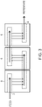
- FIG. 3 is a cross-section diagram of a SPTFF system showing fluidly-connected manifold segments 6 from three adjacent filtration modules.
- Vertical arrows indicate the direction of the flow path through parallel cassettes (not shown) that are stacked on the sides of the manifold segments 6 and project into and out of the page.
- Horizontal arrows indicate the direction of the flow path between manifold segments 6, which have a manifold arrangement (dashed lines) designed to serialize feed flow. Feed enters the system at the left through a feed inlet 3 and exits at the right through a retentate outlet 4. The permeate path is not shown for simplicity.
- Manifold segments that do not have fully-bored manifolds for carrying feed and retentate can be used to prevent parallel flow of feed and retentate, respectively, between adjacent manifold segments to facilitate a serial flow path between modules.
- manifold segments will contain a separate third manifold for carrying permeate that does extend the entire length of the segment for carrying permeate to adjacent segments.
- valves e.g., sanitary valves
- Valves are positioned in the manifolds that carry feed and retentate to block liquid from flowing in a parallel fashion into adjacent manifold segments.
- the use of valves to prevent parallel flow is particularly desirable when the manifold segments are fully bored, such that the first, second and third manifolds each extend completely through the manifold segment.
- Suitable seals for placement in manifolds include, but are not limited to, rings (e.g., o-rings, metal rings), molding, packing, sealants and gaskets.
- the seal is a gasket, such as, for example, a gasket that closes off an opening or a gasket having a length sufficient to closes off any dead volume between the opening and a first passage in a manifold.
- the gasket is flexible and sanitary (e.g., a gasket that is non-shedding, cleanable, sanitizable, and has low extractables).
- the gasket can include an elastomeric material or metal (e.g., a metal foil).
- An exemplary gasket is part# A84MP-G from Newman Gasket Co., Riverside, OH.
- valves instead of seals provides greater operational flexibility by permitting parallel flow between manifold segments when the valves are open, and serial flow when the valves are closed.
- Suitable valves for use in manifolds include, for example, pinch valves (e.g., diaphragm valve).
- the valve is low shear and sanitary (e.g., compatible, non-toxic, sanitizable, non-shedding).
- sanitary valve is a valve that can maintain a sterile connection regardless of whether the valve is open or closed.
- a sanitary valve will be compatible, non-toxic, sanitizable and non-shedding.
- the manifold segment in each filtration module is also fluidly connected to one or more TFF cassettes (e.g., one or more separate TFF cassettes, one or more TFF cassettes packaged in a single cassette holder).
- TFF cassettes e.g., one or more separate TFF cassettes, one or more TFF cassettes packaged in a single cassette holder.
- the manifold segment can be fluidly connected to TFF cassettes through a flow channel that extends from the first, or feed, manifold in the manifold segment through the plurality of TFF cassettes, and a retentate flow channel that extends through the plurality of TFF cassettes back to the second, or retentate, channel in the manifold segment.
- each filtration module can accommodate up to about 10 m 2 of filtration membrane area on each face of the manifold segment for a total of about 20 m 2 of area per filtration module.
- the total filtration area of a filtration module is about 20 m 2 or less, such as, for example, about 10 m 2 , about 5 m 2 , about 2 m 2 , about 1 m 2 , about 0.5 m 2 or about 0.1 m 2 of filtration membrane area. Accordingly the number of cassettes that can be stacked on each side of the manifold segment depends on the membrane area of the particular cassette (see, e.g., Table 1).
- the filtration modules in an SPTFF system each contain the same number and arrangement of TFF cassettes.
- Table 1 Exemplary Numbers of Particular EMD Millipore TFF Cassettes Suitable for the SPTFF and TFF Systems Described Herein Cassettes Holder Area (m 2 ) Cassette type area(m 2 ) Number of cassettes/side of manifold segment Number of cassettes/level of TFF system Levels/Stacked Filtration Modules 4 levels Pellicon ® 2 (EMD Millipore) EMD Millipore Catalogue Number P2B030A25 2.5 1 to 4 1 to 8 1 to 6 80 P2C030C25 2.5 1 to 4 1 to 8 1 to 6 80 P2C030V25 2.0 1 to 4 1 to 8 1 to 6 64 P2GVPPC25 2.5 1 to 4 1 to 8 1 to 6 80 P2B030A05 0.5 20 40 1 to 6 80 Pellicon ® 3 (EMD Millipore) EMD Millipore Catalogue Number P3C030C10
- TFF cassettes are located on both faces of the manifold segment.
- TFF cassettes e.g., about 1, 2, 3, 4, 5, 6, 7, 8, 9, 10 or more TFF cassettes
- TFF cassettes are located on only one face of the manifold segment.
- the number of TFF cassettes on each face of the manifold segment can differ or be the same.
- the total number of TFF cassettes on each face of the manifold segment is identical.
- the cassettes used in SPTFF processes can be configured to be processed in series, in parallel or both. Processing in series can improve conversion by increasing mass transfer through operation at lower feed flow rates. Although processing the cassettes in series can improve SPTFF performance and product recovery, parallel processing is often preferred for flushing SPTFF assemblies with liquids to remove preservative or storage solution, measure permeability, equilibrate the membranes, clean the membranes, or prepare the membranes for storage, particularly because serial processing requires additional time and material (e.g., water, buffer, cleaning solutions, storage solutions), which increases the overall cost of operation compared to parallel processing.
- serial processing requires additional time and material (e.g., water, buffer, cleaning solutions, storage solutions), which increases the overall cost of operation compared to parallel processing.
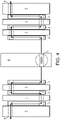
- FIG. 4 is diagram depicting a top view of a single level in an SPTFF system that includes diverter plates 1.
- a central manifold segment/block 6 comprising a feed inlet 3 is fluidly connected to three TFF cassettes 2 on each of the two sides/faces of the block.
- Diverter plates 1 between the first and second, and second and third, cassettes 2 on each side ensure a serial flow path through the cassettes.
- End plates 7 after the third cassette on each side contain retentate outlets 4. Arrows show the direction of the flow path through the system. Dashed lines show the locations of conduits for feed and retentate flow.
- the TFF cassettes can be configured for operation in parallel mode and in series mode.
- one or more valves e.g., sanitary valves
- the valves can be attached to the cassettes directly or positioned on tubing or piping between adjacent cassettes.
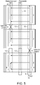
- FIG. 5 depicts three TFF cassettes 2 that are fluidly connected through flow channels 8 for feed and retentate.
- a first valve 9 is located on a flow channel 8 between the bottom and middle cassettes, and a second valve 9 is located on a flow channel between the middle and top cassettes.
- Valve-less spool pieces 10 are also positioned on the feed and retentate flow channels 8, and on a permeate flow channel 11, between cassettes. Feed enters the cassettes through a feed inlet 3 and exits the cassettes through a retentate outlet 4.
- the valves 9 in the diagram are open to allow for parallel processing of the cassettes 2 (e.g., for flushing or cleaning the assembly). When the valves 9 are both closed, the cassettes 2 are processed serially (e.g., for product processing and recovery).
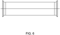
- the spool piece is an open conduit with sanitary ends that connects the retentate channel from one process holder to the feed channel of the following process holder, or connects the permeates channels of adjacent process holders.
- the length of the spool piece is chosen to match that of the sanitary valve so the assembly has a balanced height.
- An exemplary spool piece is depicted in FIG. 6 .
- the spool piece in FIG. 6 includes an open cylindrical body capable of acting as a fluid conduit with a flange located at each end.
- the SPTFF systems can include one or more filtration modules with cassettes that are configured for processing in parallel, and one or more filtration modules with cassettes that are configured for processing in series (e.g., using valves, gaskets or diverter plates).
- the filtration modules with cassettes that are configured for processing in parallel precede the filtration modules having cassettes that are configured for processing in series in the SPTFF system.
- all of the filtration modules in an SPTFF system have cassettes that are configured for processing in parallel, except for the last, or final, filtration module, which has cassettes arranged for processing in series (e.g., using diverter plates) (see, e.g., FIG. 4 ).
- TFF cassettes that are useful for the methods described herein include, but are not limited to, TFF cassettes supplied by EMD Millipore Corporation (Billerica, MA), such as, for example, Pellicon ® cassettes (e.g., Pellicon ® 2 cassettes, Pellicon ® 2 Mini cassettes, Pellicon ® 2 Maxi cassettes, Pellicon ® 3 cassettes) with Biomax TM membrane, Ultracel TM membrane or Durapore ® membrane.
- Pellicon ® cassettes e.g., Pellicon ® 2 cassettes, Pellicon ® 2 Mini cassettes, Pellicon ® 2 Maxi cassettes, Pellicon ® 3 cassettes
- Biomax TM membrane Ultracel TM membrane or Durapore ® membrane.
- TFF cassettes that can be used in the methods described herein include, for example, Centrasette TM cassettes and Cadence TM single-use cassettes (Pall Corporation, Port Washington, NY), Kvick TM Flow cassettes (GE Healthcare Bio-Sciences, Piscataway, NJ) and Hydrosart ® cassettes (Sartorius AG, Bohemia, NY).
- An end plate or cassette holder is generally used to hold, or seal, the TFF cassettes in the filtration module.
- the end plates and cassette holders can be fitted for use with particular cassettes.
- Examples of commercially-available end plates and cassette holders that are suitable for use in the SPTFF systems employed in the methods described herein include, but are not limited to, Pellicon ® cassette holders (EMD Millipore Corporation, Billerica, MA) such as, for example, Pellicon ® 2 miniholders, acrylic Pellicon ® holders, stainless steel Pellicon ® holders, process scale Pellicon ® holders.
- cassette holders include, but are not limited to, Centramate TM TFF membrane cassette holders, Centrasette TM TFF membrane cassette holders, Maximate TM TFF membrane cassette holders and Maxisette TM TFF membrane cassette holders (Pall Corporation, Port Washington, NY).
- existing cassette holders e.g., Pellicon ® cassette holders (EMD Millipore Corporation)
- EMD Millipore Corporation EMD Millipore Corporation
- the filtration modules in the SPTFF system are stacked (e.g., in a vertical stack) to form levels, wherein each level comprises a single filtration module.
- the system can include about 2, 3, 4, 5 or more stacked filtration modules.
- the SPTFF system typically contains about 5 stacked filtration modules (e.g., a 5-level system), with each filtration module preferably having an effective filtration area of about 20 m 2 per module.
- FIG. 7 is a diagram showing an isometric view of an SPTFF system having three vertically-stacked filtration modules 5 that are processed in series as a result of the arrangement of the manifolds (shown as cylinders) in the manifold segments 6. Heavy black circles show points where fluid enters or exits a manifold. Three parallel TFF cassettes 2 are shown projecting from the left side of each manifold segment 6 in each of the three filtration modules 5 and being held in place by an end plate 7. Feed solution is pumped from the feed container 12 into the SPTFF system through a feed inlet 3 on the manifold segment 6 of the bottom module 5.
- the SPTFF systems used in the methods described herein also include a feed inlet and retentate outlet.
- the feed inlet is positioned on the first filtration module in the SPTFF system, and is, in general, connected on one end to a conduit (e.g., pipe, tube) that is connected to the feed tank and is connected on the other end to the first manifold in the manifold segment in the first module to receive feed into the system.
- the retentate outlet is positioned on the last, or final, filtration module in the SPTFF system, and is typically connected on one end to the second manifold in the manifold segment in the last module and is connected on the other end to a conduit (e.g., pipe, channel) that is connected to a retentate container.
- SPTFF systems useful for performing the methods described herein can further contain one or more additional components useful for performing SPTFF processes including, but not limited to, the following, examples of which are known in the art: one or more sampling ports, a T-line (e.g., for in-line buffer addition), a pressure sensor, a diaphragm for a pressure sensor, a valve sensor to indicate whether any valves in the system are open or closed, and a flow meter.
- the SPTFF system includes a sampling port (e.g., sanitary sampling port) at one or more locations in the system.
- sampling ports can be included at the end of the retentate line, the permeate line, or both.
- the sampling port will be located on the manifold segment in a filtration module.
- the SPTFF system lacks diverter plates.
- one or more components of the SPTFF system can be disposable.
- Disposable TFF system components are well known and are available commercially.
- the disposable components are typically made from disposable materials (e.g., plastic, rubber, metal), preferably plastic.
- Exemplary disposable components for SPTFF assemblies include, but are not limited to, components of Flexware ® assemblies for Mobius ® FlexReady Solution for TFF (EMD Millipore Corporation, Billerica, MA).
- Other disposable components for SPTFF assemblies include, for example, components of Allegro TM TFF assemblies (Pall Corporation, Port Washington, NY).
- an embodiment of the invention relates to a method of filtering a liquid feed, comprising passing a liquid feed through a tangential flow filtration (TFF) system, recovering permeate and a portion of the retentate from the system in separate containers without recirculation through the TFF system, and recirculating the remainder of the retentate through the TFF system at least once.
- Retentate is recirculated during operation of the entire filtration process or at certain times during operation of the filtration process.
- recirculating all or a portion of the retentate during start up provides a method by which to ensure that system has reached equilibrium and the retentate has achieved the desired concentration prior to collecting it into the product vessel. It also provides a convenient way to respond to system upsets during processing to provide a more robust process.
- the fraction of retentate that is recirculated can be adjusted via modulation of the pump or control valve as a way to tune the system in order to assure consistent retentate concentration and/or consistent retentate flow rate to the product collection vessel every run even if feedstock protein concentration, new membrane permeability, membrane fouling, membrane permeability, or membrane mass transfer or pressure drop varies from batch to batch.
- the TFF systems employed in the TFF methods of the invention involving recirculation may additionally include at least one pump or control valve for recirculating retentate through all or part of the system and includes at least one conduit for recirculating (e.g., carrying) retentate.
- At least about 50% of the retentate is collected after a single pass, while the remainder of the retentate is recirculated.
- about 10% or less (e.g., about 0.5%, about 1 %, about 2%, about 5%, about 10%) of the retentate is recirculated after the first pass through the TFF system.
- the amount of retentate that is recirculated can be controlled using, for example, a pump or a valve.
- a flow meter can be used to provide a process value for the pump or valve to control the amount of retentate that is recirculated.
- the valve or pump and/or flow meter is/are positioned on the retentate outlet or flow line carrying retentate out of the system to the retentate receptacle.
- the retentate that is being recirculated can be returned to any upstream location in or before the TFF system.
- the retentate is recirculated to the feed tank.
- the retentate is recirculated to the feed line near the feed pump before the feed inlet on the TFF system.
- FIG. 8 An example TFF system configured for recirculation of the retentate is shown in FIG. 8 , where the number of filtration modules 5 arranged in series can differ depending upon system design. Feed enters the system at the left through a feed inlet 3 and a portion of the retentate is recirculated back to feed through recirculation line 16. Retentate and permeate exits the system through retentate 4 and permeate outlets 13. In an alternative configuration (not shown), the recirculation pump can be in the retentate recirculation line 16.
- the methods described herein further comprise performing diafiltration (e.g., to remove or lower the concentration of salts or solvents in the liquid feed, or to accomplish buffer exchange).
- the diafiltration is performed by concentrating the liquid feed (e.g., by SPTFF or TFF) to reduce the diafiltration volume and then restoring the feed to its starting volume by adding diafiltration solution, a process which is known in the art as discontinuous, or batch, diafiltration.
- diafiltration is performed by adding the diafiltrate solution to retentate to increase the diafiltration volume followed by concentrating the sample to restore it to its original volume.
- the diafiltration is performed by adding the diafiltration solution to unfiltered feed at the same rate that permeate is removed from the SPTFF or the TFF system, a process which is known in the art as continuous, or constant-volume, diafiltration.
- Continuous countercurrent diafiltration can be performed with the TFF systems and methods of the invention.
- Suitable diafiltration solutions are well known and include, for example, water and various aqueous buffer solutions.
- the TFF system can include a reservoir or container for diafiltration solution and one or more conduits for carrying diafiltration solution from the diafiltration solution container to the liquid feed tank.
- a preferred method is to use a single pump with multiple pump heads containing the diafiltrate addition and permeate removal flow lines (e.g., peristaltic pump from Ismatec, Glattbrugg, Switzerland). Each pump head will have closely-matched pumping rates so this process will be balanced and maintain efficient buffer exchange.
- FIG. 9 shows an exemplary configuration of three TFF modules with a loop 17 for partial retentate recirculation and potential entry points for diafiltration (DF) buffer 18.
- DF diafiltration
- a segmented permeate manifold could be introduced to enable countercurrent diafiltration. Countercurrent diafiltration is a well-known concept in the art (see, for example, H. Lutz, Ultrafiltration for Bioprocessing, 2015, p. 93).
- retentate recycle can return to a point before the feed pump or other method for pressurizing the feed, such as directing the retentate recycle to the feed tank.
Landscapes
- Chemical & Material Sciences (AREA)
- Chemical Kinetics & Catalysis (AREA)
- Engineering & Computer Science (AREA)
- Water Supply & Treatment (AREA)
- Separation Using Semi-Permeable Membranes (AREA)
- Cyclones (AREA)
- Electrical Discharge Machining, Electrochemical Machining, And Combined Machining (AREA)
Claims (12)
- Verfahren zur Filterung eines flüssigen Zulaufs, das Folgendes umfasst:a) Leiten eines flüssigen Zulaufs in einem Single-Pass-Modus durch ein Single-Pass-Tangentialflussfiltrations-(SPTFF)-System, das Folgendes umfasst:eine Vielzahl von Filtrationsmodulen (5), die so gestapelt sind, dass sie Ebenen bilden, wobei jede Ebene ein einzelnes Filtrationsmodul (5) umfasst und die Vielzahl von Filtrationsmodulen (5) in Fluidverbindung stehen, wobei jedes Filtrationsmodul (5) Folgendes umfasst:ein Verteilersegment (6), das einen ersten Verteiler zum Aufnehmen und Befördern des Zulaufs in das Filtrationsmodul (5), einen zweiten Verteiler zum Aufnehmen und Befördern von Retentat aus dem Filtrationsmodul (5) hinaus und einen dritten Verteiler zum Aufnehmen und Befördern von Permeat durch das Filtrationsmodul (5) umfasst;eine Vielzahl von TFF-Kassetten (2), die an einer oder beiden Flächen des Verteilersegments (6) gestapelt sind und mit diesem in Fluidverbindung stehen;einen Zulaufeinlass (3) am ersten Filtrationsmodul (5) im System;einen Retentatauslass (4) am letzten Filtrationsmodul (5) im System; undVentile, die in dem ersten und in dem zweiten Verteiler positioniert sind, wobei die Ventile parallele Strömung zwischen Verteilersegmenten ermöglichen, wenn die Ventile geöffnet sind, und serielle Strömung zwischen Verteilersegmenten ermöglichen, wenn die Ventile geschlossen sind;wobei das SPTFF-System einen Flüssigkeitsströmungsweg hat, der parallel durch die Kassetten (2) in jedem Filtrationsmodul (5) und seriell durch die Verteilersegmente (6) in angrenzenden Filtrationsmodulen (5) verläuft, indem der erste Verteiler in jedem Verteilersegment (6) mit dem zweiten Verteiler eines angrenzenden Verteilersegments (6) so gekoppelt wird, dass das Retentat eines Moduls (5) als Zulauf für das nächste Modul (5) dient, mit der Ausnahme, dass der erste Verteiler im ersten Filtrationsmodul (5) im System mit dem Zulaufeinlass (3) verbunden ist und der zweite Verteiler im letzten Filtrationsmodul (5) im System mit dem Retentatauslass (4) verbunden ist; undb) Rückgewinnen des Retentats und des Permeats aus dem System in getrennten Behältern (14, 15) ohne Rückführung durch das SPTFF-System, wodurch der flüssige Zulauf gefiltert wird.
- Verfahren zur Filterung eines flüssigen Zulaufs, das Folgendes umfasst:a) Leiten eines flüssigen Zulaufs durch ein Tangentialflussfiltrations-(TFF)-System, das Folgendes umfasst:eine Vielzahl von Filtrationsmodulen (5), die so gestapelt sind, dass sie Ebenen bilden, wobei jede Ebene ein einzelnes Filtrationsmodul (5) umfasst und die Vielzahl von Filtrationsmodulen (5) in Fluidverbindung stehen, wobei jedes Filtrationsmodul (5) Folgendes umfasst:ein Verteilersegment (6), das einen ersten Verteiler zum Aufnehmen und Befördern des Zulaufs in das Filtrationsmodul (5), einen zweiten Verteiler zum Aufnehmen und Befördern von Retentat aus dem Filtrationsmodul (5) hinaus und einen dritten Verteiler zum Aufnehmen und Befördern von Permeat durch das Filtrationsmodul (5) umfasst;eine Vielzahl von TFF-Kassetten (2), die an einer oder beiden Flächen des Verteilersegments (6) gestapelt sind und mit diesem in Fluidverbindung stehen;einen Zulaufeinlass (3) am ersten Filtrationsmodul (5) im System;einen Retentatauslass (4) am letzten Filtrationsmodul (5) im System;eine Rückführungsschleife (16) zum Rückführen von Retentat durch das ganze System oder einen Teil des Systems;mindestens eine Leitung zum Rückführen von Retentat; undVentile, die in dem ersten und in dem zweiten Verteiler positioniert sind, wobei die Ventile parallele Strömung zwischen Verteilersegmenten ermöglichen, wenn die Ventile geöffnet sind, und serielle Strömung zwischen Verteilersegmenten ermöglichen, wenn die Ventile geschlossen sind;wobei das TFF-System einen Flüssigkeitsströmungsweg hat, der parallel durch die Kassetten (2) in jedem Filtrationsmodul (5) und seriell durch die Verteilersegmente (6) in angrenzenden Filtrationsmodulen (5) verläuft, indem der erste Verteiler in jedem Verteilersegment (6) mit dem zweiten Verteiler eines angrenzenden Verteilersegments (6) so gekoppelt wird, dass das Retentat eines Moduls (5) als Zulauf für das nächste Modul (5) dient, mit der Ausnahme, dass der erste Verteiler im ersten Filtrationsmodul (5) im System mit dem Zulaufeinlass (3) verbunden ist und der zweite Verteiler im letzten Filtrationsmodul (5) im System mit dem Retentatauslass (4) verbunden ist; undb) Rückgewinnen von Permeat in einem Permeatbehälter und eines Teils des Retentats aus dem System in einem separaten Retentatbehälter (14, 15) ohne Rückführung durch das TFF-System; undc) Rückführen des restlichen Retentats durch das TFF-System mindestens einmal, wodurch der flüssige Zulauf gefiltert wird.
- Verfahren nach Anspruch 1 oder Anspruch 2, wobei jedes Filtrationsmodul (5) eine oder mehrere TFF-Kassetten (2) an einer oder beiden Flächen des Verteilersegments (6) umfasst.
- Verfahren nach Anspruch 1 oder Anspruch 2, wobei die Filtrationsfläche für jedes Filtrationsmodul (5) ungefähr 20 m2 oder weniger, ungefähr 10 m2, ungefähr 1 m2 oder ungefähr 0,1 m2 beträgt.
- Verfahren nach Anspruch 1 oder Anspruch 2, wobei das mindestens eine Filtrationsmodul (5) ferner Ventile (9) an Strömungskanälen zwischen den TFF-Kassetten (2) umfasst, wobei die Kassetten (2) parallel abgearbeitet werden, wenn die Ventile (9) geöffnet sind, oder seriell abgearbeitet werden, wenn die Ventile (9) geschlossen sind.
- Verfahren nach Anspruch 1 oder Anspruch 2, ferner umfassend einen Diafiltrationsschritt, wobei der Diafiltrationsschritt Konzentrations- und Verdünnungsschritte umfasst.
- Verfahren nach Anspruch 1, wobei das SPTFF-System ferner Folgendes umfasst:ein Reservoir für Diafiltrationslösung und eine Leitung zum Abgeben von Diafiltration in das Zulaufreservoir (12) odereines oder mehreres von Folgendem: eine oder mehrere Probenentnahmeöffnungen, eine T-Leitung für Inline-Pufferzugabe, einen Drucksensor, eine Membran für einen Drucksensor.
- Verfahren nach Anspruch 1, wobei das SPTFF-System keine Umlenkplatten hat.
- Verfahren nach Anspruch 2, wobei:ungefähr 10% oder weniger des Retentats nach dem ersten Durchlauf durch das TFF-System zurückgeführt werden oderRetentat in den Zulaufbehälter (12) oder nach einer Zulaufpumpe in die Zulaufleitung zurückgeführt wird.
- Verfahren nach Anspruch 2, wobei das TFF-System ein Ventil oder einen Durchflussmesser umfasst, das/der am Retentatauslass oder an der Leitung, die das Retentat von dem System in den Retentatbehälter (14) befördert, positioniert ist, um die Menge an Retentat, die zurückgeführt wird, zu steuern.
- Verfahren nach Anspruch 2, wobei das TFF-System:ferner eines oder mehreres von Folgendem umfasst: eine oder mehrere Probenentnahmeöffnungen, eine T-Leitung für Inline-Pufferzugabe, einen Drucksensor, eine Membran für einen Drucksensor und ein Reservoir für Diafiltrationslösung und eine Leitung zum Abgeben von Diafiltration in das Zulaufreservoir, oderkeine Umlenkplatten hat.
- Verfahren nach Anspruch 2, wobei jedes der Filtrationsmodule (5) eine andere Filtrationsfläche enthält.
Applications Claiming Priority (2)
| Application Number | Priority Date | Filing Date | Title |
|---|---|---|---|
| US201462043811P | 2014-08-29 | 2014-08-29 | |
| PCT/US2015/047574 WO2016033546A1 (en) | 2014-08-29 | 2015-08-28 | Single pass tangential flow filtration systems and tangential flow filtration systems with recirculation of retentate |
Publications (2)
| Publication Number | Publication Date |
|---|---|
| EP3185996A1 EP3185996A1 (de) | 2017-07-05 |
| EP3185996B1 true EP3185996B1 (de) | 2022-06-15 |
Family
ID=54064624
Family Applications (1)
| Application Number | Title | Priority Date | Filing Date |
|---|---|---|---|
| EP15760041.2A Active EP3185996B1 (de) | 2014-08-29 | 2015-08-28 | Einzelschritt-querstromfilterungssysteme und querstromfilterungssysteme mit retentat-rückführung |
Country Status (7)
| Country | Link |
|---|---|
| US (3) | US10195550B2 (de) |
| EP (1) | EP3185996B1 (de) |
| KR (3) | KR102188947B1 (de) |
| CN (1) | CN105745009B (de) |
| ES (1) | ES2926043T3 (de) |
| SG (2) | SG11201508664VA (de) |
| WO (1) | WO2016033546A1 (de) |
Families Citing this family (26)
| Publication number | Priority date | Publication date | Assignee | Title |
|---|---|---|---|---|
| ES2981634T3 (es) | 2014-05-15 | 2024-10-09 | Insmed Incorporated | Métodos para tratar infecciones micobacterianas pulmonares no tuberculosas |
| WO2015195453A2 (en) | 2014-06-16 | 2015-12-23 | Emd Millipore Corporation | Methods for increasing the capacity of flow-through processes |
| US10207225B2 (en) | 2014-06-16 | 2019-02-19 | Emd Millipore Corporation | Single-pass filtration systems and processes |
| CN115463546A (zh) | 2014-06-25 | 2022-12-13 | Emd 密理博公司 | 过滤器元件、切向流过滤系统、产生进料筛网的方法 |
| US10195550B2 (en) | 2014-08-29 | 2019-02-05 | Emd Millipore Corporation | Single pass tangential flow filtration systems and tangential flow filtration systems with recirculation of retentate |
| SG11201508665QA (en) | 2014-08-29 | 2016-03-30 | Emd Millipore Corp | Processes For Filtering Liquids Using Single Pass Tangential Flow Filtration Systems AndTangential Flow Filtration Systems With Recirculation of Retentate |
| GB201600287D0 (en) * | 2016-01-07 | 2016-02-24 | Fujifilm Diosynth Biotechnologies Uk Ltd | Process |
| US10183108B2 (en) | 2016-02-04 | 2019-01-22 | Pall Corporation | Inline diafiltration with multi-channel pump |
| US10758841B2 (en) * | 2016-03-07 | 2020-09-01 | Mcmaster University | Laterally-fed membrane chromatography device |
| US10758840B2 (en) * | 2016-03-07 | 2020-09-01 | Mcmaster University | Laterally-fed membrane chromatography device |
| CA2969777A1 (en) * | 2016-06-07 | 2017-12-07 | Mcmaster University | Chromatography device and method for filtering a solute from a fluid |
| CA3077712C (en) * | 2016-06-09 | 2022-03-22 | Emd Millipore Corporation | Radial-path filter elements, systems and methods of using same |
| US11691107B2 (en) | 2017-11-13 | 2023-07-04 | Emd Millipore Corporation | Continuous diafiltration by means of tank cycling |
| EP3737421A4 (de) * | 2018-01-12 | 2022-03-16 | Immunogen, Inc. | Verfahren zur antikörper-arzneimittelkonjugation, -reinigung und -formulierung |
| DK180105B1 (en) | 2018-03-08 | 2020-05-04 | Sani Membranes Aps | A FILTER-PLATE WITH EXTERNAL FLOW AREA |
| EP3773505A4 (de) * | 2018-03-30 | 2021-12-22 | Insmed Incorporated | Verfahren zur kontinuierlichen herstellung von liposomalen arzneimittelprodukten |
| US20210253633A1 (en) * | 2018-06-08 | 2021-08-19 | Bristol-Myers Squibb Company | Single pass tangential flow filtration hybrid configurations for enhancing concentration of macromolecule solutions |
| US20210395664A1 (en) * | 2018-09-21 | 2021-12-23 | Cytiva Sweden Ab | Perfusion Bioprocessing System and Method of Operating the Same |
| CN109701393B (zh) * | 2019-01-01 | 2021-03-02 | 中国人民解放军63653部队 | 一种地下水胶体原位切向流超滤装置 |
| CN109758912A (zh) * | 2019-03-06 | 2019-05-17 | 康哲(湖南)制药有限公司 | 一种水解蛋白浓缩液专用超滤设备 |
| AU2021286651A1 (en) * | 2020-06-11 | 2023-01-19 | Regeneron Pharmaceuticals, Inc. | Methods for manufacturing viral vectors |
| KR20230145403A (ko) * | 2021-02-12 | 2023-10-17 | 카운슬 오브 사이언티픽 앤드 인더스트리얼 리서치 | 단일클론 항체의 정제 공정 |
| JP2024510951A (ja) * | 2021-03-08 | 2024-03-12 | ベーリンガー インゲルハイム インターナショナル ゲゼルシャフト ミット ベシュレンクテル ハフツング | シングルパス向流透析濾過のためのシステム及び方法 |
| CN113713621B (zh) * | 2021-08-26 | 2022-08-02 | 杭州纽创生物检测有限公司 | 一种应用于病毒的sptff装置、灌注系统及病毒料液过滤方法 |
| CN113694585B (zh) * | 2021-08-26 | 2023-01-03 | 杭州科百特过滤器材有限公司 | 一种切向流过滤组件、切向流过滤装置及灌流系统 |
| EP4299156A1 (de) | 2022-06-29 | 2024-01-03 | Sartorius Stedim Biotech GmbH | Tangentialfluss-filtrations/chromatografie-systeme, verwendung davon und verfahren zur trennung |
Family Cites Families (131)
| Publication number | Priority date | Publication date | Assignee | Title |
|---|---|---|---|---|
| US3540595A (en) | 1965-05-18 | 1970-11-17 | Miles Lowell Edwards | Membrane fluid diffusion exchange device |
| DE2322044C2 (de) | 1973-05-02 | 1983-02-03 | Eberhard Hoesch & Söhne GmbH & Co, 5160 Düren | Preßmembran für Membranplatten |
| DE2358578C3 (de) | 1973-11-24 | 1980-01-24 | Lenser Kunststoff-Presswerk Gmbh + Co Kg, 7913 Senden | Filterplatte für eine Filterpresse |
| US4028250A (en) | 1975-05-30 | 1977-06-07 | Amerace Corporation | Filtration apparatus |
| JPS5371686A (en) | 1976-12-09 | 1978-06-26 | Efu Konerii Robaato | Tubular molecule filtering apparatus |
| JPS54149384A (en) | 1978-05-15 | 1979-11-22 | Nitto Electric Ind Co Ltd | Liquid separator |
| JPS54155450A (en) | 1978-05-29 | 1979-12-07 | Hitachi Ltd | Current limiting fuse |
| JPS55109407A (en) | 1979-02-13 | 1980-08-22 | Nitto Electric Ind Co Ltd | Liquid separating apparatus and manufacture thereof |
| US4765906A (en) | 1985-03-12 | 1988-08-23 | Epoc Limited | Cross-flow filtration |
| US4874507A (en) | 1986-06-06 | 1989-10-17 | Whitlock David R | Separating constituents of a mixture of particles |
| US4756835A (en) | 1986-08-29 | 1988-07-12 | Advanced Polymer Technology, Inc. | Permeable membranes having high flux-density and low fouling-propensity |
| USD357059S (en) | 1994-03-01 | 1995-04-04 | Kopf Henry B | Flat sheet membrane mass transfer module |
| NL8702149A (nl) | 1987-09-09 | 1989-04-03 | Tno | Membraanmodule voor hyperfiltratie of ultrafiltratie van vervuilende vloeistofstromen. |
| US4956085A (en) | 1987-10-02 | 1990-09-11 | Kopf Henry B | Filter plate, filter plate element and filter comprising same |
| US5310688A (en) | 1988-10-31 | 1994-05-10 | Sepracor Inc. | Method and apparatus for eluting proteins in affinity membrane process |
| USD325070S (en) | 1989-06-09 | 1992-03-31 | Kopf Henry B | Filter sheet |
| USD327313S (en) | 1989-09-01 | 1992-06-23 | Kopf Henry B | Filter plate |
| US5096584A (en) | 1990-01-29 | 1992-03-17 | The Dow Chemical Company | Spiral-wound membrane separation device with feed and permeate/sweep fluid flow control |
| US5147542A (en) * | 1991-02-04 | 1992-09-15 | Millipore Corporation | Manifold and manifold segment for tangential flow filtration apparatus |
| US5114582A (en) | 1991-04-12 | 1992-05-19 | W. R. Grace & Co.-Conn. | Filter element and spiral-wound membrane cartridge containing same |
| JP2575158Y2 (ja) | 1991-12-13 | 1998-06-25 | 東洋濾紙株式会社 | フィルタエレメント |
| WO1993022038A1 (en) | 1992-05-01 | 1993-11-11 | Filmtec Corporation | Spiral wound membrane element |
| DK170035B1 (da) | 1992-05-04 | 1995-05-08 | Md Foods Amba | Fremgangsmåde til regulering af mælketørstofbestanddele i koncentrerede mælkeprodukter i forbindelse med ultrafiltrering |
| US5470468A (en) | 1993-10-12 | 1995-11-28 | Koch Membrane Systems, Inc. | Spiral filtration module having bypass prevention flange |
| US5599447A (en) * | 1995-06-06 | 1997-02-04 | Millipore Investment Holdings Limited | Manifold apparatus for tangential flow filtration apparatus |
| US5654025A (en) | 1995-10-30 | 1997-08-05 | Raghunath; Bala | Ultrafiltration of cooled milk |
| US6054051A (en) | 1996-01-17 | 2000-04-25 | Genentech, Inc. | Tangential-flow filtration system |
| US6077991A (en) | 1996-03-28 | 2000-06-20 | Washington State University Research Foundation | Compositions and methods for production of male-sterile plants |
| DE19711083C2 (de) | 1997-03-18 | 1999-04-29 | Sartorius Gmbh | Vorrichtung und Verfahren für die adsorptive Stofftrennung mit Adsorptionsmembranen |
| US5886154A (en) | 1997-06-20 | 1999-03-23 | Lebing; Wytold R. | Chromatographic method for high yield purification and viral inactivation of antibodies |
| JP3052958B1 (ja) | 1999-04-09 | 2000-06-19 | 東レ株式会社 | スパイラル型逆浸透膜エレメントおよび分離方法 |
| DE69942763D1 (de) | 1998-06-18 | 2010-10-28 | Toray Industries | Spiralförmiges umkehrosmosemembranelement, verwendung in einem umkehrosmosemembranmodul, vorrichtung und verfahren zur umkehrosmosetrennung unter verwendung des moduls |
| WO2000030742A1 (en) | 1998-11-23 | 2000-06-02 | Zenon Environmental Inc. | Water filtration using immersed membranes |
| JP2000271460A (ja) | 1999-01-22 | 2000-10-03 | Nitto Denko Corp | スパイラル型膜モジュールを用いた処理システムおよび処理方法 |
| US6214221B1 (en) | 1999-02-22 | 2001-04-10 | Henry B. Kopf | Method and apparatus for purification of biological substances |
| NZ513242A (en) | 1999-02-22 | 2003-10-31 | Henry B Kopf | Purification of biological substances |
| DE10000186C2 (de) | 2000-01-05 | 2003-09-04 | Sartorius Gmbh | Vorrichtung und Anlage zur Crossflow-Filtration |
| JP2001252543A (ja) | 2000-03-10 | 2001-09-18 | Toray Ind Inc | 逆浸透複合膜 |
| US6365395B1 (en) | 2000-11-03 | 2002-04-02 | Millipore Corporation | Process for removing protein aggregates and virus from a protein solution |
| US7101561B2 (en) | 2000-12-01 | 2006-09-05 | Innogenetics N.V. | Purified hepatitis C virus envelope proteins for diagnostic and therapeutic use |
| US6645380B2 (en) | 2001-12-19 | 2003-11-11 | Petro Sep International Ltd. | Membrane separation apparatus |
| LT1543038T (lt) | 2002-09-11 | 2017-07-10 | Genentech, Inc. | Baltymo gryninimas |
| AU2003261387A1 (en) | 2003-02-24 | 2004-09-17 | Gtc Biotherapeutics, Inc. | Methods of tangential flow filtration and an apparatus therefore |
| KR100531670B1 (ko) | 2003-12-03 | 2005-11-28 | 씨제이 주식회사 | 인체 인터페론 알파의 제조방법 |
| US7220358B2 (en) | 2004-02-23 | 2007-05-22 | Ecolab Inc. | Methods for treating membranes and separation facilities and membrane treatment composition |
| DK1718675T3 (da) | 2004-02-27 | 2013-07-15 | Octapharma Ag | Fremgangsmåde til at tilvejebringe en oprenset virussikker antistoftilberedning |
| US20050197496A1 (en) | 2004-03-04 | 2005-09-08 | Gtc Biotherapeutics, Inc. | Methods of protein fractionation using high performance tangential flow filtration |
| US20050218057A1 (en) | 2004-03-31 | 2005-10-06 | Ngee Lee C | Filter plate assembly |
| US20060051347A1 (en) | 2004-09-09 | 2006-03-09 | Winter Charles M | Process for concentration of antibodies and therapeutic products thereof |
| EP2550971B1 (de) | 2004-09-30 | 2016-11-09 | Bayer HealthCare LLC | Vorrichtungen und Verfahren zur integrierten kontinuierlichen Herstellung biologischer Moleküle |
| US7608188B2 (en) * | 2004-12-03 | 2009-10-27 | Board Of Regents Of The Nevada System Of Higher Education | Vacuum enhanced direct contact membrane distillation |
| JP2006247453A (ja) | 2005-03-08 | 2006-09-21 | Toray Ind Inc | 液体分離素子、およびそれを用いた逆浸透装置、逆浸透膜処理方法 |
| US20080164202A1 (en) | 2005-03-29 | 2008-07-10 | Grahamtek Technologies Singapore Pte Ltd | Manufacture Of Membranes For Desalination And Filtration |
| US20060219635A1 (en) | 2005-03-30 | 2006-10-05 | Special Membrane Technologies, Inc. | High-density filtration module |
| DE202005006286U1 (de) | 2005-04-20 | 2006-08-24 | Jvk Filtration Systems Gmbh | Kammerfilterplatte |
| DE202005006535U1 (de) | 2005-04-22 | 2006-08-31 | Jvk Filtration Systems Gmbh | Kammerfilterplatte |
| JP4587937B2 (ja) | 2005-10-31 | 2010-11-24 | 日東電工株式会社 | スパイラル型分離膜エレメント |
| CA2633349A1 (en) | 2005-12-20 | 2007-07-05 | Tangenx Technology Corporation | Filtration assembly and methods for making and using same |
| US7384549B2 (en) | 2005-12-29 | 2008-06-10 | Spf Innovations, Llc | Method and apparatus for the filtration of biological solutions |
| US8747669B1 (en) | 2005-12-29 | 2014-06-10 | Spf Innovations, Llc | Method and apparatus for the filtration of biological samples |
| EP2545976B1 (de) | 2006-02-13 | 2016-08-03 | Donaldson Company, Inc. | Gewebe mit einer feinen Faser und reaktivem, adsorptivem oder absorptivem Partikel |
| US7531632B2 (en) | 2006-02-16 | 2009-05-12 | Gtc Biotherapeutics, Inc. | Clarification of transgenic milk using depth filtration |
| US20070246406A1 (en) | 2006-03-31 | 2007-10-25 | Dibel Kevin R | Tangential flow filtration apparatuses, systems, and processes for the separation of compounds |
| JP4730236B2 (ja) | 2006-07-18 | 2011-07-20 | 栗田工業株式会社 | スパイラル型膜モジュール及び水処理方法 |
| US7959805B2 (en) | 2006-07-28 | 2011-06-14 | Millipore Corporation | Manifold adaptor plate for filtration apparatus |
| US7918999B2 (en) * | 2006-12-11 | 2011-04-05 | Pall Corporation | Filtration assemblies, filtration manifolds, filtration units, and methods of channeling permeate |
| US8210042B2 (en) | 2007-02-22 | 2012-07-03 | Dow Global Technologies Llc | Use of acoustic signals for measuring membrane fouling in spiral wound modules |
| SG146558A1 (en) | 2007-03-26 | 2008-10-30 | Millipore Corp | Cassette-style filtration apparatus |
| KR101320719B1 (ko) | 2007-08-16 | 2013-10-29 | 코오롱인더스트리 주식회사 | 중공사막 모듈의 세정 장치 및 그 방법 |
| JP5238815B2 (ja) | 2007-09-12 | 2013-07-17 | ダニスコ・ユーエス・インク | 内部汚れ付着が制御された濾過 |
| US7632404B2 (en) | 2007-11-15 | 2009-12-15 | Dionex Corporation | Barrier with a seated ion exchange bead and method |
| US8668828B2 (en) | 2007-12-05 | 2014-03-11 | Trisep Corporation | Sanitary spiral wound filtration cartridge |
| JP2009178915A (ja) | 2008-01-30 | 2009-08-13 | Tokushu Paper Mfg Co Ltd | シート状物 |
| DE102008015387B4 (de) | 2008-03-20 | 2019-01-10 | Sartorius Stedim Biotech Gmbh | Vorsterilisierbares Filtrationssystem zum Einmalgebrauch |
| DE102008020478B4 (de) | 2008-04-23 | 2011-07-21 | Sartorius Stedim Biotech GmbH, 37079 | Filtermodul und Filtereinheit |
| US8231787B2 (en) | 2008-05-06 | 2012-07-31 | Spf Innovations, Llc | Tangential flow filtration system |
| US8147735B2 (en) | 2008-07-09 | 2012-04-03 | Eltron Research & Development, Inc. | Semipermeable polymers and method for producing same |
| US8961790B2 (en) | 2008-10-17 | 2015-02-24 | General Electric Company | Separator assembly |
| US8295561B2 (en) | 2008-11-04 | 2012-10-23 | Signal Processing, Inc. | Knowledge learning system and process for fingerprint verifications |
| WO2010090864A2 (en) | 2009-01-21 | 2010-08-12 | Smartflow Technologies, Inc. | Optimization of separation for viscous suspensions |
| US9056896B2 (en) | 2009-03-27 | 2015-06-16 | Asahi Kasei Medical Co., Ltd. | Method for removing viruses from high concentration monoclonal antibody solution |
| USD651280S1 (en) | 2009-11-12 | 2011-12-27 | Hitachi Plant Technologies, Ltd. | Immersion flat filter membrane element |
| IT1397061B1 (it) | 2009-12-28 | 2012-12-28 | Kedrion Spa | Nuovo processo di purificazione su scala industriale di gammaglobuline da plasma umano per uso industriale. |
| US20120264948A1 (en) | 2009-12-30 | 2012-10-18 | Cargill, Incorporated | Membrane separation and purification of monatin |
| US8506802B1 (en) * | 2010-01-25 | 2013-08-13 | Gaston De Los Reyes | Stackable planar adsorptive devices |
| WO2011094236A2 (en) | 2010-02-01 | 2011-08-04 | Rodney Herrington | Systems and methods for filtration |
| US8661648B2 (en) | 2010-03-24 | 2014-03-04 | Dow Global Technologies Llc | Spiral wound filtration module |
| CA2810909A1 (en) | 2010-09-20 | 2012-03-29 | Abbvie Inc. | Purification of antibodies using simulated moving bed chromatography |
| WO2012039675A1 (en) | 2010-09-20 | 2012-03-29 | Lee Hock Teo | Home and commercial water filtration with online self-cleaning system |
| USD655780S1 (en) | 2010-10-26 | 2012-03-13 | Ishigaki Company Limited | Filter plate for a filter press |
| USD655779S1 (en) | 2010-10-26 | 2012-03-13 | Ishigaki Company Limited | Filter plate for a filter press |
| US8919385B2 (en) * | 2010-11-24 | 2014-12-30 | Pall Corporation | Manifold plates and fluid treatment arrangements including manifold plates |
| US20120166332A1 (en) | 2010-12-22 | 2012-06-28 | Ebay Inc. | Bill splitting system |
| WO2012091027A1 (ja) | 2010-12-28 | 2012-07-05 | 東レ株式会社 | 分離膜エレメント |
| WO2012125457A1 (en) | 2011-03-11 | 2012-09-20 | Fenwal, Inc. | Membrane separation devices, systems and methods employing same and data management systems and methods |
| EP2703066A4 (de) | 2011-04-25 | 2014-12-03 | Toray Industries | Verfahren zur reinigung eines membranmoduls |
| SI2741836T1 (sl) | 2011-08-12 | 2019-08-30 | Pall Corporation | Sestavi za obdelavo tekočin, ki vključujejo zbiralnik, in postopki obdelave tekočin |
| KR20140082677A (ko) | 2011-09-29 | 2014-07-02 | 도레이 카부시키가이샤 | 분리막 및 분리막 엘리먼트 |
| JPWO2013047746A1 (ja) | 2011-09-29 | 2015-03-26 | 東レ株式会社 | 分離膜、分離膜エレメントおよび分離膜の製造方法 |
| US9675937B2 (en) | 2011-10-19 | 2017-06-13 | General Electric Company | Spiral wound membrane permeate carrier with thin border |
| US20130146531A1 (en) | 2011-12-09 | 2013-06-13 | General Electric Company | Feed spacers for spiral wound membrane element |
| WO2013085755A2 (en) | 2011-12-09 | 2013-06-13 | General Electric Company | Feed spacers for spiral wound membrane element |
| WO2013106337A1 (en) | 2012-01-09 | 2013-07-18 | Sanofi Pasteur Biologics, Llc | Purification of flaviviruses |
| CN104136101B (zh) | 2012-02-24 | 2016-10-19 | 东丽株式会社 | 分离膜及分离膜元件 |
| JP6109492B2 (ja) | 2012-05-22 | 2017-04-05 | 株式会社ダイセル | Nf平膜とその製造方法 |
| WO2013183553A1 (ja) | 2012-06-04 | 2013-12-12 | 東レ株式会社 | 分離膜ユニットおよびこれを用いた造水方法 |
| EP2682168A1 (de) | 2012-07-02 | 2014-01-08 | Millipore Corporation | Reinigung biologischer Moleküle |
| CA149539S (en) | 2012-07-31 | 2013-12-17 | Roberto Marchetti | Filter for preparing drinks |
| US20140042072A1 (en) * | 2012-08-10 | 2014-02-13 | Pall Corporation | Fluid treatment assemblies, fluid treatment segments, and methods of making fluid treatment systems |
| CA2887684A1 (en) | 2012-10-30 | 2014-05-08 | Peter Becker | Purification of polypeptides using dual stage tangential-flow ultrafiltration |
| USD729897S1 (en) | 2013-02-19 | 2015-05-19 | General Electric Company | Endplate |
| US9376595B2 (en) | 2013-06-21 | 2016-06-28 | General Electric Company | Method and apparatus for fabricating separator assembly |
| JP2015009182A (ja) | 2013-06-27 | 2015-01-19 | 住友電気工業株式会社 | スパイラル型分離膜エレメント及びスパイラル型分離膜モジュール |
| CN105848746B (zh) | 2013-09-05 | 2019-07-09 | 豪夫迈·罗氏有限公司 | 用于层析重复利用的方法 |
| JP5606615B1 (ja) | 2013-12-05 | 2014-10-15 | 三菱重工業株式会社 | 膜分離装置、循環水利用システム |
| EP2907565A1 (de) | 2014-02-17 | 2015-08-19 | Bayer Technology Services GmbH | Dialyse-Einheit zum kontinuierlichen Puffer- bzw. Medienaustausch aus einer Proteinlösung |
| JP2017510452A (ja) | 2014-03-07 | 2017-04-13 | エイジェンシー・フォー・サイエンス,テクノロジー・アンド・リサーチ | 生物学的生成物の分画のための装置及び方法 |
| EP4218991A1 (de) | 2014-05-13 | 2023-08-02 | Amgen Inc. | Prozesssteuerungssysteme und verfahren zur verwendung mit filtern und filtrationsverfahren |
| US10207225B2 (en) | 2014-06-16 | 2019-02-19 | Emd Millipore Corporation | Single-pass filtration systems and processes |
| WO2015195453A2 (en) | 2014-06-16 | 2015-12-23 | Emd Millipore Corporation | Methods for increasing the capacity of flow-through processes |
| CN115463546A (zh) | 2014-06-25 | 2022-12-13 | Emd 密理博公司 | 过滤器元件、切向流过滤系统、产生进料筛网的方法 |
| USD741983S1 (en) | 2014-08-12 | 2015-10-27 | Sartorius Stedim Biotech Gmbh | Filter assembly |
| US10195550B2 (en) | 2014-08-29 | 2019-02-05 | Emd Millipore Corporation | Single pass tangential flow filtration systems and tangential flow filtration systems with recirculation of retentate |
| SG11201508665QA (en) | 2014-08-29 | 2016-03-30 | Emd Millipore Corp | Processes For Filtering Liquids Using Single Pass Tangential Flow Filtration Systems AndTangential Flow Filtration Systems With Recirculation of Retentate |
| USD762811S1 (en) | 2014-12-18 | 2016-08-02 | Emd Millipore Corporation | Diverter plate |
| USD761381S1 (en) | 2014-12-18 | 2016-07-12 | Emd Millipore Corporation | Retentate plate |
| ES2913118T3 (es) | 2015-06-30 | 2022-05-31 | Emd Millipore Corp | Caja de sellado para casete de filtro |
| WO2017085054A1 (en) | 2015-11-16 | 2017-05-26 | Basf Se | Nanofiltration composite membranes comprising self-assembled supramolecular separation layer |
| CN105435504A (zh) | 2015-12-02 | 2016-03-30 | 王刚 | 水处理的微颗粒物分离器 |
| CA3077712C (en) | 2016-06-09 | 2022-03-22 | Emd Millipore Corporation | Radial-path filter elements, systems and methods of using same |
| DE202018100564U1 (de) | 2018-02-01 | 2019-02-04 | Jvk Filtration Systems Gmbh | Anordnung einer Filterplatte für eine Filterpresse und einer Dichteinrichtung sowie Filterplatte |
-
2015
- 2015-08-28 US US14/839,779 patent/US10195550B2/en active Active
- 2015-08-28 WO PCT/US2015/047574 patent/WO2016033546A1/en active Application Filing
- 2015-08-28 SG SG11201508664VA patent/SG11201508664VA/en unknown
- 2015-08-28 KR KR1020187004189A patent/KR102188947B1/ko active IP Right Grant
- 2015-08-28 KR KR1020167007236A patent/KR102079585B1/ko active IP Right Grant
- 2015-08-28 ES ES15760041T patent/ES2926043T3/es active Active
- 2015-08-28 SG SG10201901555UA patent/SG10201901555UA/en unknown
- 2015-08-28 EP EP15760041.2A patent/EP3185996B1/de active Active
- 2015-08-28 KR KR1020207034849A patent/KR102235952B1/ko active IP Right Grant
- 2015-08-28 CN CN201580000716.4A patent/CN105745009B/zh active Active
-
2018
- 2018-12-03 US US16/208,018 patent/US11033839B2/en active Active
-
2021
- 2021-05-10 US US17/315,721 patent/US11679349B2/en active Active
Also Published As
| Publication number | Publication date |
|---|---|
| KR20180019753A (ko) | 2018-02-26 |
| US20210260504A1 (en) | 2021-08-26 |
| US11033839B2 (en) | 2021-06-15 |
| KR102235952B1 (ko) | 2021-04-07 |
| KR102188947B1 (ko) | 2020-12-09 |
| US11679349B2 (en) | 2023-06-20 |
| CN105745009B (zh) | 2018-09-28 |
| US10195550B2 (en) | 2019-02-05 |
| WO2016033546A1 (en) | 2016-03-03 |
| EP3185996A1 (de) | 2017-07-05 |
| SG10201901555UA (en) | 2019-03-28 |
| ES2926043T3 (es) | 2022-10-21 |
| KR20160045800A (ko) | 2016-04-27 |
| SG11201508664VA (en) | 2016-03-30 |
| US20160059159A1 (en) | 2016-03-03 |
| KR102079585B1 (ko) | 2020-02-21 |
| CN105745009A (zh) | 2016-07-06 |
| KR20200139274A (ko) | 2020-12-11 |
| US20190099702A1 (en) | 2019-04-04 |
Similar Documents
| Publication | Publication Date | Title |
|---|---|---|
| US11679349B2 (en) | Single pass tangential flow filtration systems and tangential flow filtration systems with recirculation of retentate | |
| US11278827B2 (en) | Processes for filtering liquids using single pass tangential flow filtration systems and tangential flow filtration systems with recirculation of retentate | |
| US11617988B2 (en) | Single-pass filtration systems and processes | |
| EP3710141B1 (de) | Kontinuierliche diafiltration mittels tankzyklen | |
| EP2957335B1 (de) | Single-pass-filtersysteme und verfahren | |
| EP4144434B1 (de) | Single-pass-filtersysteme und -verfahren |
Legal Events
| Date | Code | Title | Description |
|---|---|---|---|
| STAA | Information on the status of an ep patent application or granted ep patent |
Free format text: STATUS: THE INTERNATIONAL PUBLICATION HAS BEEN MADE |
|
| PUAI | Public reference made under article 153(3) epc to a published international application that has entered the european phase |
Free format text: ORIGINAL CODE: 0009012 |
|
| STAA | Information on the status of an ep patent application or granted ep patent |
Free format text: STATUS: REQUEST FOR EXAMINATION WAS MADE |
|
| 17P | Request for examination filed |
Effective date: 20150916 |
|
| AK | Designated contracting states |
Kind code of ref document: A1 Designated state(s): AL AT BE BG CH CY CZ DE DK EE ES FI FR GB GR HR HU IE IS IT LI LT LU LV MC MK MT NL NO PL PT RO RS SE SI SK SM TR |
|
| AX | Request for extension of the european patent |
Extension state: BA ME |
|
| DAV | Request for validation of the european patent (deleted) | ||
| DAX | Request for extension of the european patent (deleted) | ||
| STAA | Information on the status of an ep patent application or granted ep patent |
Free format text: STATUS: EXAMINATION IS IN PROGRESS |
|
| 17Q | First examination report despatched |
Effective date: 20180411 |
|
| STAA | Information on the status of an ep patent application or granted ep patent |
Free format text: STATUS: EXAMINATION IS IN PROGRESS |
|
| RAP1 | Party data changed (applicant data changed or rights of an application transferred) |
Owner name: EMD MILLIPORE CORPORATION |
|
| GRAP | Despatch of communication of intention to grant a patent |
Free format text: ORIGINAL CODE: EPIDOSNIGR1 |
|
| STAA | Information on the status of an ep patent application or granted ep patent |
Free format text: STATUS: GRANT OF PATENT IS INTENDED |
|
| INTG | Intention to grant announced |
Effective date: 20220224 |
|
| GRAS | Grant fee paid |
Free format text: ORIGINAL CODE: EPIDOSNIGR3 |
|
| GRAA | (expected) grant |
Free format text: ORIGINAL CODE: 0009210 |
|
| STAA | Information on the status of an ep patent application or granted ep patent |
Free format text: STATUS: THE PATENT HAS BEEN GRANTED |
|
| AK | Designated contracting states |
Kind code of ref document: B1 Designated state(s): AL AT BE BG CH CY CZ DE DK EE ES FI FR GB GR HR HU IE IS IT LI LT LU LV MC MK MT NL NO PL PT RO RS SE SI SK SM TR |
|
| REG | Reference to a national code |
Ref country code: CH Ref legal event code: EP Ref country code: GB Ref legal event code: FG4D |
|
| REG | Reference to a national code |
Ref country code: IE Ref legal event code: FG4D |
|
| REG | Reference to a national code |
Ref country code: DE Ref legal event code: R096 Ref document number: 602015079472 Country of ref document: DE |
|
| REG | Reference to a national code |
Ref country code: AT Ref legal event code: REF Ref document number: 1498018 Country of ref document: AT Kind code of ref document: T Effective date: 20220715 |
|
| REG | Reference to a national code |
Ref country code: NL Ref legal event code: FP |
|
| REG | Reference to a national code |
Ref country code: LT Ref legal event code: MG9D |
|
| REG | Reference to a national code |
Ref country code: ES Ref legal event code: FG2A Ref document number: 2926043 Country of ref document: ES Kind code of ref document: T3 Effective date: 20221021 |
|
| PG25 | Lapsed in a contracting state [announced via postgrant information from national office to epo] |
Ref country code: SE Free format text: LAPSE BECAUSE OF FAILURE TO SUBMIT A TRANSLATION OF THE DESCRIPTION OR TO PAY THE FEE WITHIN THE PRESCRIBED TIME-LIMIT Effective date: 20220615 Ref country code: NO Free format text: LAPSE BECAUSE OF FAILURE TO SUBMIT A TRANSLATION OF THE DESCRIPTION OR TO PAY THE FEE WITHIN THE PRESCRIBED TIME-LIMIT Effective date: 20220915 Ref country code: LT Free format text: LAPSE BECAUSE OF FAILURE TO SUBMIT A TRANSLATION OF THE DESCRIPTION OR TO PAY THE FEE WITHIN THE PRESCRIBED TIME-LIMIT Effective date: 20220615 Ref country code: HR Free format text: LAPSE BECAUSE OF FAILURE TO SUBMIT A TRANSLATION OF THE DESCRIPTION OR TO PAY THE FEE WITHIN THE PRESCRIBED TIME-LIMIT Effective date: 20220615 Ref country code: GR Free format text: LAPSE BECAUSE OF FAILURE TO SUBMIT A TRANSLATION OF THE DESCRIPTION OR TO PAY THE FEE WITHIN THE PRESCRIBED TIME-LIMIT Effective date: 20220916 Ref country code: FI Free format text: LAPSE BECAUSE OF FAILURE TO SUBMIT A TRANSLATION OF THE DESCRIPTION OR TO PAY THE FEE WITHIN THE PRESCRIBED TIME-LIMIT Effective date: 20220615 Ref country code: BG Free format text: LAPSE BECAUSE OF FAILURE TO SUBMIT A TRANSLATION OF THE DESCRIPTION OR TO PAY THE FEE WITHIN THE PRESCRIBED TIME-LIMIT Effective date: 20220915 |
|
| REG | Reference to a national code |
Ref country code: AT Ref legal event code: MK05 Ref document number: 1498018 Country of ref document: AT Kind code of ref document: T Effective date: 20220615 |
|
| PG25 | Lapsed in a contracting state [announced via postgrant information from national office to epo] |
Ref country code: RS Free format text: LAPSE BECAUSE OF FAILURE TO SUBMIT A TRANSLATION OF THE DESCRIPTION OR TO PAY THE FEE WITHIN THE PRESCRIBED TIME-LIMIT Effective date: 20220615 Ref country code: LV Free format text: LAPSE BECAUSE OF FAILURE TO SUBMIT A TRANSLATION OF THE DESCRIPTION OR TO PAY THE FEE WITHIN THE PRESCRIBED TIME-LIMIT Effective date: 20220615 |
|
| PG25 | Lapsed in a contracting state [announced via postgrant information from national office to epo] |
Ref country code: SM Free format text: LAPSE BECAUSE OF FAILURE TO SUBMIT A TRANSLATION OF THE DESCRIPTION OR TO PAY THE FEE WITHIN THE PRESCRIBED TIME-LIMIT Effective date: 20220615 Ref country code: SK Free format text: LAPSE BECAUSE OF FAILURE TO SUBMIT A TRANSLATION OF THE DESCRIPTION OR TO PAY THE FEE WITHIN THE PRESCRIBED TIME-LIMIT Effective date: 20220615 Ref country code: RO Free format text: LAPSE BECAUSE OF FAILURE TO SUBMIT A TRANSLATION OF THE DESCRIPTION OR TO PAY THE FEE WITHIN THE PRESCRIBED TIME-LIMIT Effective date: 20220615 Ref country code: PT Free format text: LAPSE BECAUSE OF FAILURE TO SUBMIT A TRANSLATION OF THE DESCRIPTION OR TO PAY THE FEE WITHIN THE PRESCRIBED TIME-LIMIT Effective date: 20221017 Ref country code: EE Free format text: LAPSE BECAUSE OF FAILURE TO SUBMIT A TRANSLATION OF THE DESCRIPTION OR TO PAY THE FEE WITHIN THE PRESCRIBED TIME-LIMIT Effective date: 20220615 Ref country code: CZ Free format text: LAPSE BECAUSE OF FAILURE TO SUBMIT A TRANSLATION OF THE DESCRIPTION OR TO PAY THE FEE WITHIN THE PRESCRIBED TIME-LIMIT Effective date: 20220615 Ref country code: AT Free format text: LAPSE BECAUSE OF FAILURE TO SUBMIT A TRANSLATION OF THE DESCRIPTION OR TO PAY THE FEE WITHIN THE PRESCRIBED TIME-LIMIT Effective date: 20220615 |
|
| PG25 | Lapsed in a contracting state [announced via postgrant information from national office to epo] |
Ref country code: PL Free format text: LAPSE BECAUSE OF FAILURE TO SUBMIT A TRANSLATION OF THE DESCRIPTION OR TO PAY THE FEE WITHIN THE PRESCRIBED TIME-LIMIT Effective date: 20220615 Ref country code: IS Free format text: LAPSE BECAUSE OF FAILURE TO SUBMIT A TRANSLATION OF THE DESCRIPTION OR TO PAY THE FEE WITHIN THE PRESCRIBED TIME-LIMIT Effective date: 20221015 |
|
| REG | Reference to a national code |
Ref country code: DE Ref legal event code: R097 Ref document number: 602015079472 Country of ref document: DE |
|
| PG25 | Lapsed in a contracting state [announced via postgrant information from national office to epo] |
Ref country code: MC Free format text: LAPSE BECAUSE OF FAILURE TO SUBMIT A TRANSLATION OF THE DESCRIPTION OR TO PAY THE FEE WITHIN THE PRESCRIBED TIME-LIMIT Effective date: 20220615 Ref country code: AL Free format text: LAPSE BECAUSE OF FAILURE TO SUBMIT A TRANSLATION OF THE DESCRIPTION OR TO PAY THE FEE WITHIN THE PRESCRIBED TIME-LIMIT Effective date: 20220615 |
|
| PLBE | No opposition filed within time limit |
Free format text: ORIGINAL CODE: 0009261 |
|
| STAA | Information on the status of an ep patent application or granted ep patent |
Free format text: STATUS: NO OPPOSITION FILED WITHIN TIME LIMIT |
|
| PG25 | Lapsed in a contracting state [announced via postgrant information from national office to epo] |
Ref country code: LU Free format text: LAPSE BECAUSE OF NON-PAYMENT OF DUE FEES Effective date: 20220828 Ref country code: DK Free format text: LAPSE BECAUSE OF FAILURE TO SUBMIT A TRANSLATION OF THE DESCRIPTION OR TO PAY THE FEE WITHIN THE PRESCRIBED TIME-LIMIT Effective date: 20220615 |
|
| 26N | No opposition filed |
Effective date: 20230316 |
|
| PG25 | Lapsed in a contracting state [announced via postgrant information from national office to epo] |
Ref country code: SI Free format text: LAPSE BECAUSE OF FAILURE TO SUBMIT A TRANSLATION OF THE DESCRIPTION OR TO PAY THE FEE WITHIN THE PRESCRIBED TIME-LIMIT Effective date: 20220615 |
|
| P01 | Opt-out of the competence of the unified patent court (upc) registered |
Effective date: 20230602 |
|
| PGFP | Annual fee paid to national office [announced via postgrant information from national office to epo] |
Ref country code: IT Payment date: 20230711 Year of fee payment: 9 Ref country code: ES Payment date: 20230901 Year of fee payment: 9 Ref country code: CH Payment date: 20230902 Year of fee payment: 9 |
|
| PG25 | Lapsed in a contracting state [announced via postgrant information from national office to epo] |
Ref country code: HU Free format text: LAPSE BECAUSE OF FAILURE TO SUBMIT A TRANSLATION OF THE DESCRIPTION OR TO PAY THE FEE WITHIN THE PRESCRIBED TIME-LIMIT; INVALID AB INITIO Effective date: 20150828 |
|
| PG25 | Lapsed in a contracting state [announced via postgrant information from national office to epo] |
Ref country code: CY Free format text: LAPSE BECAUSE OF FAILURE TO SUBMIT A TRANSLATION OF THE DESCRIPTION OR TO PAY THE FEE WITHIN THE PRESCRIBED TIME-LIMIT Effective date: 20220615 |
|
| PG25 | Lapsed in a contracting state [announced via postgrant information from national office to epo] |
Ref country code: MK Free format text: LAPSE BECAUSE OF FAILURE TO SUBMIT A TRANSLATION OF THE DESCRIPTION OR TO PAY THE FEE WITHIN THE PRESCRIBED TIME-LIMIT Effective date: 20220615 |
|
| PGFP | Annual fee paid to national office [announced via postgrant information from national office to epo] |
Ref country code: NL Payment date: 20240705 Year of fee payment: 10 |
|
| PG25 | Lapsed in a contracting state [announced via postgrant information from national office to epo] |
Ref country code: MT Free format text: LAPSE BECAUSE OF FAILURE TO SUBMIT A TRANSLATION OF THE DESCRIPTION OR TO PAY THE FEE WITHIN THE PRESCRIBED TIME-LIMIT Effective date: 20220615 |
|
| PGFP | Annual fee paid to national office [announced via postgrant information from national office to epo] |
Ref country code: DE Payment date: 20240702 Year of fee payment: 10 Ref country code: IE Payment date: 20240702 Year of fee payment: 10 |
|
| PGFP | Annual fee paid to national office [announced via postgrant information from national office to epo] |
Ref country code: GB Payment date: 20240701 Year of fee payment: 10 |
|
| PGFP | Annual fee paid to national office [announced via postgrant information from national office to epo] |
Ref country code: BE Payment date: 20240703 Year of fee payment: 10 |
|
| PGFP | Annual fee paid to national office [announced via postgrant information from national office to epo] |
Ref country code: FR Payment date: 20240702 Year of fee payment: 10 |