EP3185657B1 - Steuergerät - Google Patents
Steuergerät Download PDFInfo
- Publication number
- EP3185657B1 EP3185657B1 EP16205974.5A EP16205974A EP3185657B1 EP 3185657 B1 EP3185657 B1 EP 3185657B1 EP 16205974 A EP16205974 A EP 16205974A EP 3185657 B1 EP3185657 B1 EP 3185657B1
- Authority
- EP
- European Patent Office
- Prior art keywords
- printed circuit
- flexible printed
- controller
- circuit board
- annular base
- Prior art date
- Legal status (The legal status is an assumption and is not a legal conclusion. Google has not performed a legal analysis and makes no representation as to the accuracy of the status listed.)
- Active
Links
Images

Classifications
-
- H—ELECTRICITY
- H05—ELECTRIC TECHNIQUES NOT OTHERWISE PROVIDED FOR
- H05K—PRINTED CIRCUITS; CASINGS OR CONSTRUCTIONAL DETAILS OF ELECTRIC APPARATUS; MANUFACTURE OF ASSEMBLAGES OF ELECTRICAL COMPONENTS
- H05K1/00—Printed circuits
- H05K1/02—Details
- H05K1/14—Structural association of two or more printed circuits
- H05K1/147—Structural association of two or more printed circuits at least one of the printed circuits being bent or folded, e.g. by using a flexible printed circuit
-
- G—PHYSICS
- G01—MEASURING; TESTING
- G01J—MEASUREMENT OF INTENSITY, VELOCITY, SPECTRAL CONTENT, POLARISATION, PHASE OR PULSE CHARACTERISTICS OF INFRARED, VISIBLE OR ULTRAVIOLET LIGHT; COLORIMETRY; RADIATION PYROMETRY
- G01J1/00—Photometry, e.g. photographic exposure meter
- G01J1/42—Photometry, e.g. photographic exposure meter using electric radiation detectors
- G01J1/44—Electric circuits
-
- H—ELECTRICITY
- H05—ELECTRIC TECHNIQUES NOT OTHERWISE PROVIDED FOR
- H05K—PRINTED CIRCUITS; CASINGS OR CONSTRUCTIONAL DETAILS OF ELECTRIC APPARATUS; MANUFACTURE OF ASSEMBLAGES OF ELECTRICAL COMPONENTS
- H05K1/00—Printed circuits
- H05K1/02—Details
- H05K1/0277—Bendability or stretchability details
- H05K1/028—Bending or folding regions of flexible printed circuits
-
- H—ELECTRICITY
- H05—ELECTRIC TECHNIQUES NOT OTHERWISE PROVIDED FOR
- H05K—PRINTED CIRCUITS; CASINGS OR CONSTRUCTIONAL DETAILS OF ELECTRIC APPARATUS; MANUFACTURE OF ASSEMBLAGES OF ELECTRICAL COMPONENTS
- H05K1/00—Printed circuits
- H05K1/18—Printed circuits structurally associated with non-printed electric components
- H05K1/189—Printed circuits structurally associated with non-printed electric components characterised by the use of a flexible or folded printed circuit
-
- H—ELECTRICITY
- H05—ELECTRIC TECHNIQUES NOT OTHERWISE PROVIDED FOR
- H05K—PRINTED CIRCUITS; CASINGS OR CONSTRUCTIONAL DETAILS OF ELECTRIC APPARATUS; MANUFACTURE OF ASSEMBLAGES OF ELECTRICAL COMPONENTS
- H05K7/00—Constructional details common to different types of electric apparatus
- H05K7/02—Arrangements of circuit components or wiring on supporting structure
- H05K7/06—Arrangements of circuit components or wiring on supporting structure on insulating boards, e.g. wiring harnesses
-
- H—ELECTRICITY
- H05—ELECTRIC TECHNIQUES NOT OTHERWISE PROVIDED FOR
- H05K—PRINTED CIRCUITS; CASINGS OR CONSTRUCTIONAL DETAILS OF ELECTRIC APPARATUS; MANUFACTURE OF ASSEMBLAGES OF ELECTRICAL COMPONENTS
- H05K1/00—Printed circuits
- H05K1/02—Details
- H05K1/0277—Bendability or stretchability details
- H05K1/0283—Stretchable printed circuits
-
- H—ELECTRICITY
- H05—ELECTRIC TECHNIQUES NOT OTHERWISE PROVIDED FOR
- H05K—PRINTED CIRCUITS; CASINGS OR CONSTRUCTIONAL DETAILS OF ELECTRIC APPARATUS; MANUFACTURE OF ASSEMBLAGES OF ELECTRICAL COMPONENTS
- H05K1/00—Printed circuits
- H05K1/02—Details
- H05K1/14—Structural association of two or more printed circuits
- H05K1/148—Arrangements of two or more hingeably connected rigid printed circuit boards, i.e. connected by flexible means
-
- H—ELECTRICITY
- H05—ELECTRIC TECHNIQUES NOT OTHERWISE PROVIDED FOR
- H05K—PRINTED CIRCUITS; CASINGS OR CONSTRUCTIONAL DETAILS OF ELECTRIC APPARATUS; MANUFACTURE OF ASSEMBLAGES OF ELECTRICAL COMPONENTS
- H05K2201/00—Indexing scheme relating to printed circuits covered by H05K1/00
- H05K2201/05—Flexible printed circuits [FPCs]
- H05K2201/052—Branched
-
- H—ELECTRICITY
- H05—ELECTRIC TECHNIQUES NOT OTHERWISE PROVIDED FOR
- H05K—PRINTED CIRCUITS; CASINGS OR CONSTRUCTIONAL DETAILS OF ELECTRIC APPARATUS; MANUFACTURE OF ASSEMBLAGES OF ELECTRICAL COMPONENTS
- H05K2201/00—Indexing scheme relating to printed circuits covered by H05K1/00
- H05K2201/05—Flexible printed circuits [FPCs]
- H05K2201/053—Tails
-
- H—ELECTRICITY
- H05—ELECTRIC TECHNIQUES NOT OTHERWISE PROVIDED FOR
- H05K—PRINTED CIRCUITS; CASINGS OR CONSTRUCTIONAL DETAILS OF ELECTRIC APPARATUS; MANUFACTURE OF ASSEMBLAGES OF ELECTRICAL COMPONENTS
- H05K2201/00—Indexing scheme relating to printed circuits covered by H05K1/00
- H05K2201/05—Flexible printed circuits [FPCs]
- H05K2201/055—Folded back on itself
-
- H—ELECTRICITY
- H05—ELECTRIC TECHNIQUES NOT OTHERWISE PROVIDED FOR
- H05K—PRINTED CIRCUITS; CASINGS OR CONSTRUCTIONAL DETAILS OF ELECTRIC APPARATUS; MANUFACTURE OF ASSEMBLAGES OF ELECTRICAL COMPONENTS
- H05K2201/00—Indexing scheme relating to printed circuits covered by H05K1/00
- H05K2201/05—Flexible printed circuits [FPCs]
- H05K2201/056—Folded around rigid support or component
-
- H—ELECTRICITY
- H05—ELECTRIC TECHNIQUES NOT OTHERWISE PROVIDED FOR
- H05K—PRINTED CIRCUITS; CASINGS OR CONSTRUCTIONAL DETAILS OF ELECTRIC APPARATUS; MANUFACTURE OF ASSEMBLAGES OF ELECTRICAL COMPONENTS
- H05K2201/00—Indexing scheme relating to printed circuits covered by H05K1/00
- H05K2201/05—Flexible printed circuits [FPCs]
- H05K2201/058—Direct connection between two or more FPCs or between flexible parts of rigid PCBs
-
- H—ELECTRICITY
- H05—ELECTRIC TECHNIQUES NOT OTHERWISE PROVIDED FOR
- H05K—PRINTED CIRCUITS; CASINGS OR CONSTRUCTIONAL DETAILS OF ELECTRIC APPARATUS; MANUFACTURE OF ASSEMBLAGES OF ELECTRICAL COMPONENTS
- H05K2201/00—Indexing scheme relating to printed circuits covered by H05K1/00
- H05K2201/09—Shape and layout
- H05K2201/09009—Substrate related
- H05K2201/09027—Non-rectangular flat PCB, e.g. circular
-
- H—ELECTRICITY
- H05—ELECTRIC TECHNIQUES NOT OTHERWISE PROVIDED FOR
- H05K—PRINTED CIRCUITS; CASINGS OR CONSTRUCTIONAL DETAILS OF ELECTRIC APPARATUS; MANUFACTURE OF ASSEMBLAGES OF ELECTRICAL COMPONENTS
- H05K2201/00—Indexing scheme relating to printed circuits covered by H05K1/00
- H05K2201/10—Details of components or other objects attached to or integrated in a printed circuit board
- H05K2201/10007—Types of components
- H05K2201/10151—Sensor
-
- H—ELECTRICITY
- H05—ELECTRIC TECHNIQUES NOT OTHERWISE PROVIDED FOR
- H05K—PRINTED CIRCUITS; CASINGS OR CONSTRUCTIONAL DETAILS OF ELECTRIC APPARATUS; MANUFACTURE OF ASSEMBLAGES OF ELECTRICAL COMPONENTS
- H05K3/00—Apparatus or processes for manufacturing printed circuits
- H05K3/30—Assembling printed circuits with electric components, e.g. with resistor
- H05K3/32—Assembling printed circuits with electric components, e.g. with resistor electrically connecting electric components or wires to printed circuits
- H05K3/325—Assembling printed circuits with electric components, e.g. with resistor electrically connecting electric components or wires to printed circuits by abutting or pinching, i.e. without alloying process; mechanical auxiliary parts therefor
- H05K3/326—Assembling printed circuits with electric components, e.g. with resistor electrically connecting electric components or wires to printed circuits by abutting or pinching, i.e. without alloying process; mechanical auxiliary parts therefor the printed circuit having integral resilient or deformable parts, e.g. tabs or parts of flexible circuits
-
- H—ELECTRICITY
- H05—ELECTRIC TECHNIQUES NOT OTHERWISE PROVIDED FOR
- H05K—PRINTED CIRCUITS; CASINGS OR CONSTRUCTIONAL DETAILS OF ELECTRIC APPARATUS; MANUFACTURE OF ASSEMBLAGES OF ELECTRICAL COMPONENTS
- H05K7/00—Constructional details common to different types of electric apparatus
- H05K7/02—Arrangements of circuit components or wiring on supporting structure
- H05K7/023—Stackable modules
Definitions
- the application relates to a flexible printed circuit board, a supporting holder, and a controller, and particularly relates to a flexible printed circuit board, a supporting holder for supporting the flexible printed circuit board, and a controller using the flexible printed circuit board and the supporting holder.
- the sensing components may be disposed on the flexible printed circuit board and then disposed on a supporting holder to be assembled into the controller. Accordingly, the controller is able to detect a signal sent by a signal source through the sensing components (to sense an infrared ray emitted by the signal source through an infrared sensor, for example) so as to generate a corresponding control signal.
- the sensing components may also be other types of electronic components to enable the controller to execute corresponding operations.
- the controller may use a plurality of strip flexible printed circuit boards to carry the electronic components in multiple directions of the supporting holder.
- tolerances may easily occur in the assembly of the flexible printed circuit boards in the controller, and the assembly process is relatively complicated.
- the document US 2014/0067056 A1 shows a molded interconnect device that can carry a Hall sensor for transducing a position of a rotor of the implantable blood pump.
- the molded interconnect device includes one or more integrated electronic circuit traces configured to electrically connect the hall sensor with a printed circuit board of the implantable blood pump, and the molded interconnect device is configured to be mounted to the printed circuit board.
- the document US 2012/0006907 A1 relates to a device for acquiring predetermined state variables inside a room, in particular in the interior of a motor vehicle, with at least one temperature sensor an with a humidity sensor, hat least regions of which are enclosed by a housing, wherein a first temperature sensor exhibits at least one contact surface for abutting against a perimeter surface bordering the room, and that at least one second temperature sensor is provided inside the housing for acquiring the room temperature.
- the contact surface is thereby a surface piece of a printed circuit board section of a printed circuit board, which encompasses elastic characteristics, wherein the printed circuit board section encompasses a plurality of surface pieces, which are angled relative to one another, and the temperature sensors are arranged at different surface pieces.
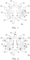
- FIG. 1 is a schematic top view of a flexible printed circuit board according to an illustrative example not part of the invention.
- FIG. 2 is a schematic top view of the flexible printed circuit board of FIG. 1 with electronic components thereon.
- a flexible printed circuit board 100 includes an annular main board 110 and a plurality of branches 120.
- the branches 120 are connected with and surround the annular main board 110.
- Each of the branches 120 includes an extension portion 122 and a bonding portion 124.
- the extension portion 122 connects the bonding portion 124 with the annular main board 110.
- the flexible printed circuit board 100 is adapted for a controller 50 (as shown in the figures described below), wherein an electronic component 52 required by the controller 50 is disposed on the bonding portion 124 (as shown in FIG. 2 ) and the flexible printed circuit board 100 is further connected with the electronic parts in the controller 50.
- the flexible printed circuit board 100 of the application is not necessarily applied to the controller and may also be used in other electronic devices.
- the annular main board 110 of the flexible printed circuit board 100 has a substantially annular shape.
- the branches 120 surround the annular main board 110 and are integrally connected with a lateral side of the annular main board 110, and it may be deemed that the branches 120 are formed by extending from the lateral side of the annular main board 110.
- Each of the branches 120 includes the extension portion 122 and the bonding portion 124, wherein the extension portion 122 extends from the lateral side of the annular main board 110 and the bonding portion 124 is connected with the corresponding extension portion 122 and is located at an end of the branch 120.
- the number of the branches 120 in this embodiment is eleven, for example, wherein two of the branches 120 extend toward a center of the annular main board 110 from an inner side of the annular main board 110 while the other nine of the branches 120 extend outward from an outer side of the annular main board 110. Therefore, the flexible printed circuit board 100 includes eleven bonding portions 124. Nevertheless, it should be noted that the application is not intended to limit the number and locations of the branches 120/the bonding portions 124, which may be adjusted as required.
- the flexible printed circuit board 100 further includes a connection portion 130 and connection lines (not shown).
- the connection portion 130 is connected with the annular main board 110 and is located between two adjacent branches 120.
- the connection lines are disposed on the annular main board 110 and the branches 120 and extend from the connection portion 130 to the bonding portion 124 of each of the branches 120.
- the electronic component 52 is disposed on the bonding portion 124 of each of the branches 120 in a proper manner (fixed on a conductive pad on the bonding portion 124 via a conductive adhesive or solder, for example) to be electrically connected with the connection lines on the corresponding branch 120.
- a width W1 of each of the bonding portions 124 is greater than a width W2 of the corresponding extension portion 122, so as to facilitate disposing the electronic component 52 on each bonding portion 124, and the extension portion 122 may be reduced in size as long as it is sufficient for disposing the corresponding connection lines, such that the assembly of the branch 120 is more flexible for further application.
- a reinforcement plate may be disposed on a back surface (opposite to the surface where the electronic component is disposed) of the bonding portion 124.
- the flexible printed circuit board 100 with the electronic component 52 thereon is further applied to the controller 50 (as shown in the figures described below), the flexible printed circuit board 100 is suitable to be connected with the electronic parts in the controller 50 via the connection portion 130, such that the electronic component 52 required by the controller 50 is electrically connected with the electronic parts in the controller 50 via the connection lines on the corresponding branch 120 and the connection portion 130.
- the flexible printed circuit board 100 of this embodiment obtains multiple bonding portions 124 with an annular distribution without need of connecting manner and therefore the assembly process is relatively simple.
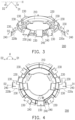
- FIG. 3 is a schematic perspective view of a supporting holder used in an embodiment of the invention.
- FIG. 4 is a schematic top view of the supporting holder of FIG. 3 .
- a supporting holder 200 includes an annular base 210, two wing structures 220a and 220b, and a plurality of mounting portions 230.
- the wing structures 220a and 220b extend outward from the annular base 210.
- the mounting portions 230 are disposed on the annular base 210 and the wing structures 220a and 220b.
- the supporting holder 200 is adapted for supporting the flexible printed circuit board 100 in the controller 50 (as shown in the figures described below).
- the application is not intended to limit the flexible printed circuit board supported by the supporting holder 200 and the application thereof. That is, the supporting holder 200 may also be used to support other flexible printed circuit boards or other electronic parts, and may also be used in other electronic parts.
- the annular base 210 of the supporting holder 200 has a substantially annular shape.
- the wing structures 220a and 220b are connected integrally with a lateral side of the annular base 210 and extend outward from the annular base 210.
- the mounting portions 230 are disposed on the annular base 210 and the wing structures 220a and 220b.
- the number of the mounting portions 230 is eleven, for example, wherein two of the mounting portions 230 are located on the annular base 210 close to an inner side of the annular base 210, seven are located on the annular base 210 close to an outer side of the annular base 210, and two are respectively located on the wing structures 220a and 220b.
- the application is not intended to limit the number and locations of the mounting portions 230, which may be adjusted as required.
- the annular base 210 and the wing structures 220a and 220b all have the mounting portions 230 thereon.
- the wing structures 220a and 220b have an angle ⁇ (as shown in FIG. 4 ) therebetween, and each of the wing structures 220a and 220b respectively tilts and extends toward a side of the annular base 210 to form a tilt angle ⁇ (as shown in FIG. 3 ) with respect to a horizontal reference plane H where the annular base 210 is located.
- the angle ⁇ refers to an angle between extending directions D1 and D2 of the wing structures 220a and 220b when the supporting holder 200 is viewed from above (as shown in FIG.
- the tilt angle ⁇ refers to an angle of the extending directions D1 and D2 of the wing structures 220a and 220b with respect to the horizontal reference plane H where the annular base 210 is located when the supporting holder 200 is in a horizontal state.
- the angle ⁇ is 180 degrees, for example, and the wing structures 220a and 220b tilt and extend toward the same side of the annular base 210 and preferably have the same tilt angle ⁇ , such that the wing structures 220a and 220b are symmetrically located on two opposite sides of the the annular base 210.
- the application is not limited thereto and the configuration may be adjusted as required.
- each mounting portion 230 further has a positioning structure 240.
- the positioning structure 240 protrudes from the mounting portion 230 and extends in two directions to restrict the corresponding bonding portion 124.
- the positioning structure 240 is an L-shaped rib that extends in two directions and protrudes from two adjacent lateral sides of the mounting portion 230, for example. Therefore, when the flexible printed circuit board 100 is disposed on the supporting holder 200, the bonding portion 124 is restricted by the positioning structure 240 in two directions to be disposed at a fixed position on the mounting portion 230. That is, two adjacent lateral sides of the bonding portion 124 may be restricted by the L-shaped positioning structure 240 to be disposed on the mounting portion 230 easily.
- the design of the positioning structure 240 helps to position the bonding portion 124 on the mounting portion 230. Nevertheless, the application is not intended to limit the type of the positioning structure 240 or whether the positioning structure 240 is disposed, which may be adjusted as required.
- the supporting holder 200 when the supporting holder 200 is further applied to the controller 50 (as shown in the figures described below), the supporting holder 200 is suitable for supporting the aforementioned flexible printed circuit board 100 (as shown in FIG. 1 and FIG. 2 ) to be assembled to other electronic parts (not shown), so as to fix the flexible printed circuit board 100 in the controller 50. More specifically, when the flexible printed circuit board 100 is disposed on the supporting holder 200, the annular main board 110 and the branches 120 of the flexible printed circuit board 100 are located on the annular base 210 and the wing structures 220a and 220b, and the bonding portion 124 of each of the branches 120 is located on the corresponding mounting portion 230.
- the supporting holder 200 increases the configuration range of the mounting portions 230 through the wing structures 220a and 220b, which also increases the number and configuration range of the bonding portions 124 of the flexible printed circuit board 100 and the electronic components 52 on the bonding portions 124 (as shown in FIG. 1 and FIG. 2 ) and thereby improves the operational efficiency of the controller 50 (as shown in the figures described below) using the supporting holder 200.
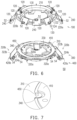
- FIG. 5 is a schematic exploded view of a controller according to an embodiment of the invention.
- FIG. 6 is a schematic view of assembly of the controller of FIG. 5 .
- FIG. 7 is a partially enlarged view of the controller of FIG. 6 .
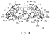
- FIG. 8 is a schematic perspective view of the controller of FIG. 5 .
- the controller 50 includes two flexible printed circuit boards 100 and 300 and two supporting holders 200 and 400.
- the flexible printed circuit boards 100 and 300 are disposed on the supporting holders 200 and 400 correspondingly, and the supporting holders 200 and 400 are assembled to each other.
- the number of the flexible printed circuit boards and the supporting holders may be one or more, and the flexible printed circuit boards and the supporting holders correspond to each other. Nevertheless, the application does not exclude the possibility of using one single supporting holder to support multiple flexible printed circuit boards, which may be adjusted as required.
- the flexible printed circuit board 100 is disposed on the supporting holder 200, wherein the annular main board 110 is disposed on the annular base 210 and the branches 120 are disposed on the annular base 210 and the wing structures 220a and 220b, such that the bonding portions 124 are located on the mounting portions 230 correspondingly.
- the annular base 210 has a top surface S1 and a bottom surface S2 opposite to each other, and the mounting portions 230 are located on the top surface S1 of the annular base 210 and the wing structures 220a and 220b.
- the annular main board 110 of the flexible printed circuit board 100 is disposed on the bottom surface S2 of the annular base 210, and the branches 120 extend to the top surface S1 of the annular base 210 and the wing structures 220a and 220b through the corresponding extension portions 122, such that the bonding portion 124 of each of the branches 120 is located on the mounting portion 230 correspondingly, as shown in the upper parts of FIG. 5 and FIG. 6 . Accordingly, the bonding portions 124 with the electronic components 52 thereon are disposed on the mounting portions 230 and have an annular distribution on the annular base 210 and the wing structures 220a and 220b of the supporting holder 200. However, in other embodiments not shown here, the flexible printed circuit board 100 may also be disposed on the top surface S1 of the annular base 210. Nevertheless, the application is not limited to the embodiment described above.
- the flexible printed circuit board 300 and the supporting holder 400 have similar structural features.
- the flexible printed circuit board 300 includes an annular main board 310, a plurality of branches 320a and 320b, a connection portion 330, and connection lines (not shown).
- the supporting holder 400 includes an annular base 410, two wing structures 420a and 420b, and a plurality of mounting portions 430.
- the structural features of the annular main board 310, the branches 320a and 320b, the connection portion 330, and the connection lines have been specified in the descriptions of the annular main board 110, the branches 120, the connection portion 130, and the connection lines.
- annular base 410 the structural features of the annular base 410, the wing structures 420a and 420b, and the mounting portions 430 have been specified in the descriptions of the annular base 210, the wing structures 220a and 220b, and the mounting portions 230. Thus, descriptions of similar parts are not repeated hereinafter.
- a main difference between the flexible printed circuit board 300 and the aforementioned flexible printed circuit board 100 is that the number of the branches 320a and 320b of the flexible printed circuit board 300 is different from the number of the branches 120 of the aforementioned flexible printed circuit board 100, and the branch 320b has different structural features from the branches 120 and 320a.
- the number of the branches 320a and 320b of the flexible printed circuit board 300 is nine, for example.
- Three branches 320a extend toward a center of the annular main board 310 from an inner side of the annular main board 310 and include an extension portion 322a and a bonding portion 324a.
- the other four branches 320a extend outward from an outer side of the annular main board 310 and include the extension portion 322a and the bonding portion 324a.
- the extension portion 322a and the bonding portion 324a also have the structural design of the aforementioned extension portion 122 and the bonding portion 124 (for example, the width W1 of each of the bonding portions 124 is greater than the width W2 of the corresponding extension portion 122).
- two branches 320b extend outward from the outer side of the annular main board 310 and include an extension portion 322b and three bonding portions 324b, wherein the bonding portions 324b are disposed on three adjacent lateral sides of the extension portion 322b, and a width of the extension portion 322b is greater than a width of each of the corresponding bonding portions 324b.
- the above design is made such that the bonding portions 124, 324a, and 324b of the flexible printed circuit boards 100 and 300 are staggered and not in contact with one another after being assembled. Nevertheless, the application is not intended to limit the number and locations of the branches 320a and 320b, which may be adjusted as required.
- the flexible printed circuit board 300 includes thirteen bonding portions 324a and 324b, and the electronic components 54 may be disposed on the bonding portions 324a and 324b of the branches 320a and 320b in a proper manner to be electrically connected with the connection lines on the corresponding branches 320a and 320b.
- the flexible printed circuit board 300 with the electronic components 54 thereon is further used in the controller 50, the flexible printed circuit board 300 is suitable to be connected with the electronic parts in the controller 50 via the connection portion 330, such that the electronic components 54 required by the controller 50 are electrically connected with the electronic parts in the controller 50 via the connection lines on the corresponding branches 320a and 320b and the connection portion 330.
- the flexible printed circuit board 300 used in this embodiment obtains the multiple bonding portions 324a and 324b with an annular distribution without need of connecting manner and therefore the assembly process is relatively simple.
- a main difference between the supporting holder 400 and the aforementioned supporting holder 200 is that, in accordance with the structural design of the branch 320b of the flexible printed circuit board 300, the wing structures 420a and 420b include a plurality of mounting portions 430 correspondingly.
- the number of the mounting portions 430 in this embodiment is thirteen, for example, wherein three mounting portions 430 are located on the annular base 410 close to the inner side of the annular base 410, four mounting portions 430 are located on the annular base 410 close to the outer side of the annular base 410, and six mounting portions 430 are respectively located on three adjacent lateral surfaces of the two wing structures 420a and 420b (that is, each of the wing structures 420a and 420b corresponds to three mounting portions 430).
- the application is not intended to limit the number and locations of the mounting portions 430, which may be adjusted as required.
- the annular base 410 and the wing structures 420a and 420b all have the mounting portions 430 thereon.
- the wing structures 420a and 420b may also have technical features similar to the angle ⁇ and the tilt angle ⁇ (as shown in FIG. 3 and FIG. 4 ) of the aforementioned wing structures 220a and 220b.
- an angle between the wing structures 420a and 420b is the same as the angle ⁇ between the wing structures 220a and 220b
- a tilt angle of each of the wing structures 420a and 420b is the same as the tilt angle ⁇ of each of the wing structures 220a and 220b, such that the wing structures 420a and 420b and the wing structures 220a and 220b are suitable to be stacked and assembled.
- each of the mounting portions 430 may have a positioning structure (e.g. the L-shaped positioning structure 240 aforementioned). Nevertheless, the application is not intended to limit the type of the positioning structure or whether the positioning structure is disposed. Accordingly, the supporting holder 400 is suitable for supporting the flexible printed circuit board 300 and being assembled to other electronic parts not shown here, so as to fix the flexible printed circuit board 300 in the controller 50, wherein the annular main board 310 and the branches 320a and 320b of the flexible printed circuit board 300 are located on the annular base 410 and the wing structures 420a and 420b, and the bonding portions 324a and 324b of the branches 320a and 320b are located on the mounting portions 430 correspondingly.
- the annular main board 310 and the branches 320a and 320b of the flexible printed circuit board 300 are located on the annular base 410 and the wing structures 420a and 420b, and the bonding portions 324a and 324b of the branches 320a and 320b are located on
- the annular base 410 has a top surface S3 and a bottom surface S4 opposite to each other, and the mounting portions 430 are located on the bottom surface S4 of the annular base 410 and the wing structures 420a and 420b.
- the annular main board 310 of the flexible printed circuit board 300 is disposed on the top surface S3 of the annular base 410, and the branches 320a and 320b extend to the bottom surface S4 of the annular base 410 and the wing structures 420a and 420b through the corresponding extension portions 322a and 322b, such that the bonding portions 324a and 324b of the branches 320a and 320b are located on the mounting portions 430 correspondingly, as shown in the lower parts of FIG.
- the bonding portions 324a and 324b with the electronic components 54 thereon are disposed on the mounting portions 430 and have an annular distribution on the annular base 410 and the wing structures 420a and 420b of the supporting holder 400.
- the flexible printed circuit board 300 may also be disposed on the bottom surface S4 of the annular base 410. Nevertheless, the application is not limited to the embodiment described above.
- the supporting holder 400 of this embodiment increases the configuration range of the mounting portions 430 through the wing structures 420a and 420b, which also increases the number and configuration range of the bonding portions 324a and 324b of the flexible printed circuit board 300 and the electronic components 54 on the bonding portions 324a and 324b and thereby improves the operational efficiency of the controller 50 (as shown in the figures described below) using the supporting holder 400.
- a method of assembling the controller 50 includes respectively disposing the flexible printed circuit boards 100 and 300 on the corresponding supporting holders 200 and 400, for example, by fixing the flexible printed circuit boards 100 and 300 onto the corresponding supporting holders 200 and 400 by an adhesive (not shown), so as to form the upper and lower parts (as shown in FIG. 6 ).
- the annular main boards 110 and 310 of the flexible printed circuit boards 100 and 300 are located on the bottom surface S2 of the annular base 210 and the top surface S3 of the annular base 410 correspondingly to be sandwiched between the supporting holders 200 and 400, and the branches 120, 320a, and 320b are located on the top surface S1 of the annular base 210 and the bottom surface S4 of the annular base 410 to be fixed on the outer sides of the supporting holders 200 and 400.
- the flexible printed circuit boards 100 and 300 are fixed between the supporting holders 200 and 400 and the electronic components 52 and 54 disposed on the branches 120, 320a, and 320b are located on the outer sides of the supporting holders 200 and 400 and do not overlap one another.
- the flexible printed circuit board 300 further includes a plurality of positioning structures 340 located on a periphery of the annular main board 310, which are positioning holes on the inner side or the outer side of the annular main board 310 for example
- the supporting holder 400 further includes a plurality of positioning structures 450 located on a periphery of the annular base 410, which are positioning pillars on the inner side or the outer side of the annular base 410 for example.
- the positioning structures 340 of the flexible printed circuit board 300 correspond to the positioning structures 450 of the supporting holder 400, so as to position the flexible printed circuit board 300 on the supporting holder 400.
- the angle ⁇ between the wing structures 220a and 220b, the angle between the wing structures 420a and 420b, the tilt angle ⁇ of each of the wing structures 220a and 220b, and the tilt angle of each of the wing structures 420a and 420b may affect the operational efficiency of the controller 50 as well.
- the angle ⁇ between the wing structures 220a and 220b (as shown in FIG.
- the angle between the wing structures 420a and 420b are preferably 180 degrees, but may be any angle (e.g. 45, 90, or 120 degrees) in a range of 0-180 degrees.
- the tilt angle ⁇ of each of the wing structures 220a and 220b (as shown in FIG. 3 ) and the tilt angle ⁇ of each of the wing structures 420a and 420b may be any angle in a range of 0-90 degrees, and preferably in a range of 30-70 degrees. In this embodiment, the tilt angle ⁇ is 51 degrees. Nevertheless, the application is not limited thereto and the configuration may be adjusted as required.
- the electronic components 52 and 54 are infrared sensors, for example.
- the infrared sensors serving as the electronic components 52 and 54 are disposed on the bonding portions 124, 324a, and 324b correspondingly and are located on the mounting portions 230 and 430 and have an annular distribution, such that the electronic components 52 and 54 are able to sense signal sources (for example, to receive infrared rays emitted by the signal sources) in a range of 360 degrees, so as to determine relative positions of the controller 50 and the signal sources in the space.
- the flexible printed circuit boards 100 and 300 obtain multiple bonding portions 124, 324a, and 324b with an annular distribution without need of connecting manner and therefore the assembly process is relatively simple.
- the supporting holders 200 and 400 increase the configuration range of the mounting portions 230 and 430 through the wing structures 220a, 220b, 420a, and 420b, so as to increase the number and configuration range of the bonding portions 124, 324a, and 324b of the flexible printed circuit boards 100 and 300 and the electronic components 52 and 54 on the bonding portions 124, 324a, and 324b.
- the controller 50 in addition to sensing signals in the range of 360 degrees by the electronic components 52 and 54 that have an annular distribution on the annular bases 210 and 410, the controller 50 also enhance the sensing efficiency by the electronic component 54 on the wing structures 220a, 220b, 420a, and 420b. Consequently, the operational efficiency of the controller 50 is improved.
- the electronic components 52 and 54 may be other types of sensors or electronic components, and the electronic components 52 and 54 may be the same or different to enable the controller to perform corresponding operations/functions. Nevertheless, the application is not limited thereto.
- the flexible printed circuit board includes the annular main board and the branches while the supporting holder includes the annular base, two wing structures, and multiple mounting portions located on the annular base and the wing structures. Therefore, when the flexible printed circuit board and the supporting holder are assembled to form the controller, the annular main board is disposed on the annular base and the branches are disposed on the annular base and the wing structures, such that the bonding portions of the branches and the electronic components on the bonding portions are located on the mounting portions correspondingly. Accordingly, the electronic components have an annular distribution on the flexible printed circuit board and the supporting holder and are further distributed onto the wing structures.
- the number of the flexible printed circuit boards and the number of the supporting holders may be more than one as required, and preferably the electronic components on multiple flexible printed circuit boards do not overlap one another after assembly. Accordingly, the flexible printed circuit board of the application obtains multiple bonding portions with an annular distribution without need of connecting manner and the assembly process is relatively simple. Moreover, the supporting holder of the application increases the configuration range of the mounting portions through the wing structures, so as to increase the number and configuration range of the bonding portions of the flexible printed circuit board and the electronic components on the bonding portions and thereby improve the operational efficiency of the controller of the application.
Landscapes
- Engineering & Computer Science (AREA)
- Microelectronics & Electronic Packaging (AREA)
- Physics & Mathematics (AREA)
- General Physics & Mathematics (AREA)
- Spectroscopy & Molecular Physics (AREA)
- Telephone Set Structure (AREA)
- Structure Of Printed Boards (AREA)
- Mounting Of Printed Circuit Boards And The Like (AREA)
Claims (9)
- Eine Steuervorrichtung (50), die Folgendes aufweist:mindestens eine flexible Leiterplatte (100; 300), umfassend:eine ringförmige Hauptplatine (110; 310);eine Vielzahl von Zweigen (120; 320a, 320b), die mit der ringförmigen Hauptplatine (110; 310) verbunden sind und diese umgeben, wobei jeder der Zweige (120; 320a, 320b) einen Verlängerungsabschnitt (122; 322a, 322b) und einen Verbindungsabschnitt (124; 324a, 324b) aufweist, wobei der Verlängerungsabschnitt (122; 322a, 322b) den Verbindungsabschnitt (124; 324a, 324b) mit der ringförmigen Hauptplatine (110; 310) verbindet, und wobei eine Breite jedes der Verbindungsabschnitte (124; 324a, 324b) größer ist als eine Breite des entsprechenden Verlängerungsabschnitts (122; 322a, 322b) ist,ein elektronisches Bauteil (52; 54), das auf dem Verbindungsabschnitt (124; 324a, 324b) jedes der Zweige (120; 320a; 320b) angeordnet ist, wobei das elektronische Bauteil (52, 54) elektrisch mit Verbindungsleitungen auf dem entsprechenden Zweig (120; 320a; 320b) verbunden ist; undmindestens einen Stützhalter (200; 400), der die mindestens eine flexible Leiterplatte (100; 300) stützt, wobei der mindestens eine Stützhalter (200, 400) Folgendes umfasst:eine ringförmige Basis (210; 410);zwei Flügelstrukturen (220a, 220b; 420a, 420b), die sich von der ringförmigen Basis (210; 410) nach außen erstrecken; undeine Vielzahl von Befestigungsabschnitten (230; 430), die sich auf der ringförmigen Basis (210; 410) und den Flügelstrukturen (220a, 220b; 420a, 420b) befinden, wobei die ringförmige Hauptplatine (110; 310) auf der ringförmigen Basis (210; 410) angeordnet ist, wobei zwei Zweige (120; 320a, 320b) an den jeweiligen Flügelstrukturen (220a, 220b; 420a, 420b) angeordnet sind, und wobei die anderen Zweige an der ringförmigen Basis (210; 410) angeordnet sind, so dass die Verbindungsabschnitte (124; 324a, 324b) an den Befestigungsabschnitten (230; 430) entsprechend angeordnet sind.
- Die Steuervorrichtung (50) nach Anspruch 1, wobei die flexible Leiterplatte (100; 300) ferner einen Verbindungsabschnitt (130; 330) umfasst, der mit der ringförmigen Hauptplatine (110; 310) verbunden ist und zwischen zwei benachbarten Zweigen (120; 320a, 320b) angeordnet ist.
- Die Steuervorrichtung (50) gemäß Anspruch 1, wobei die Erstreckungsrichtungen (D1, D2) der Flügelstrukturen (220a, 220b; 420a, 420b) einen Winkel (θ) zwischen sich aufweisen, wenn der Stützhalter (200) von oben betrachtet wird, und der Winkel (θ) 180 Grad beträgt.
- Die Steuervorrichtung (50) gemäß Anspruch 1, wobei jede der Flügelstrukturen (220a, 220b; 420a, 420b) sich zu einer Seite der ringförmigen Basis (210; 410) neigt und erstreckt und einen Neigungswinkel in Bezug auf eine horizontale Bezugsebene bildet, in der sich die ringförmige Basis (210; 410) befindet.
- Die Steuervorrichtung (50) gemäß Anspruch 4, wobei die Flügelstrukturen (220a, 220b; 420a, 420b) sich in Richtung derselben Seite der ringförmigen Basis (210; 410) neigen und erstrecken.
- Die Steuervorrichtung (50) nach Anspruch 1, wobei die mindestens eine flexible Leiterplatte (100; 300) ferner eine Vielzahl von Positionierungsstrukturen (340) umfasst, die sich an einem Umfang der ringförmigen Hauptplatine (110) befinden, und der mindestens eine Stützhalter (200; 400) ferner eine Vielzahl von Positionierungsstrukturen (240; 450) umfasst, die sich an einem Umfang der ringförmigen Basis (210; 410) befinden, und wobei die Positionierungsstrukturen (340) der flexiblen Leiterplatte (100; 300) den Positionierungsstrukturen (240; 450) des Stützhalters (200; 400) entsprechen, um die flexible Leiterplatte (100; 300) auf dem Stützhalter (200; 400) zu positionieren.
- Die Steuervorrichtung (50) nach Anspruch 1, wobei jeder der Befestigungsabschnitte (230; 430) eine Positionierungsstruktur (240; 340, 450) umfasst, die von dem Befestigungsabschnitt (230; 430) vorsteht und sich in zwei Richtungen erstreckt.
- Die Steuervorrichtung (50) nach Anspruch 1, wobei die Anzahl der mindestens einen flexiblen Leiterplatte (100; 300) und die Anzahl der mindestens einen Stützhalter (200; 400) größer als eins ist, und wobei die flexiblen Leiterplatten (100; 300) entsprechend auf den Stützhaltern (200; 400) angeordnet sind und die Stützhalter (200; 400) miteinander verbunden sind.
- Die Steuervorrichtung (50) nach Anspruch 8, wobei die Verbindungsabschnitte (124; 324a, 324b) der flexiblen Leiterplatten (100; 300) nach dem Zusammenbau nicht miteinander in Kontakt sind.
Applications Claiming Priority (2)
| Application Number | Priority Date | Filing Date | Title |
|---|---|---|---|
| US201562387201P | 2015-12-24 | 2015-12-24 | |
| US15/076,668 US10292268B2 (en) | 2015-12-24 | 2016-03-22 | Flexible printed circuit board, supporting holder and controller |
Publications (3)
| Publication Number | Publication Date |
|---|---|
| EP3185657A1 EP3185657A1 (de) | 2017-06-28 |
| EP3185657C0 EP3185657C0 (de) | 2025-06-18 |
| EP3185657B1 true EP3185657B1 (de) | 2025-06-18 |
Family
ID=57609727
Family Applications (1)
| Application Number | Title | Priority Date | Filing Date |
|---|---|---|---|
| EP16205974.5A Active EP3185657B1 (de) | 2015-12-24 | 2016-12-21 | Steuergerät |
Country Status (2)
| Country | Link |
|---|---|
| US (1) | US10292268B2 (de) |
| EP (1) | EP3185657B1 (de) |
Families Citing this family (3)
| Publication number | Priority date | Publication date | Assignee | Title |
|---|---|---|---|---|
| CN110383209B (zh) * | 2017-02-24 | 2023-08-11 | 慧与发展有限责任合伙企业 | 用于组装出可扩展模块的方法、可扩展设备及系统 |
| USD954665S1 (en) * | 2019-05-03 | 2022-06-14 | Lumileds Holding B.V. | Flexible circuit board |
| CN110568402A (zh) * | 2019-09-04 | 2019-12-13 | 京东方科技集团股份有限公司 | 一种电子设备、空间定位系统及方法 |
Family Cites Families (13)
| Publication number | Priority date | Publication date | Assignee | Title |
|---|---|---|---|---|
| US5508781A (en) * | 1993-03-15 | 1996-04-16 | Olympus Optical Co., Ltd. | Printed circuit board |
| JPH06273654A (ja) | 1993-03-24 | 1994-09-30 | Olympus Optical Co Ltd | フレキシブルプリント基板 |
| US5436745A (en) * | 1994-02-23 | 1995-07-25 | Ois Optical Imaging Systems, Inc. | Flex circuit board for liquid crystal display |
| US5543586A (en) | 1994-03-11 | 1996-08-06 | The Panda Project | Apparatus having inner layers supporting surface-mount components |
| CN100574555C (zh) | 2007-07-04 | 2009-12-23 | 富葵精密组件(深圳)有限公司 | 软性电路板基板 |
| CN101453826B (zh) * | 2007-11-28 | 2011-12-21 | 深圳富泰宏精密工业有限公司 | 印刷电路板堆叠结构 |
| CN101466207B (zh) | 2007-12-19 | 2011-11-16 | 富葵精密组件(深圳)有限公司 | 电路板及其制作方法 |
| TWI359629B (en) | 2008-12-19 | 2012-03-01 | Foxsemicon Integrated Tech Inc | Rigid printed circuit board, printed circuit board |
| DE102010026563A1 (de) | 2010-07-08 | 2012-01-12 | Hella Kgaa Hueck & Co. | Sensoranordnung zur Erfassung von Zustandsgrößen |
| EP2531772B1 (de) * | 2010-08-10 | 2015-09-30 | OSRAM GmbH | Leiterplatte mit mindestens einer halbleiterlichtquelle, auflage für die leiterplatte, system aus der leiterplatte und der auflage sowie verfahren zum befestigen der leiterplatte an der auflage |
| WO2014036419A1 (en) * | 2012-08-31 | 2014-03-06 | Thoratec Corporation | Hall sensor mounting in an implantable blood pump |
| CN203775513U (zh) | 2013-12-30 | 2014-08-13 | 昆山维信诺显示技术有限公司 | 一种柔性电路板 |
| US20150257278A1 (en) | 2014-03-06 | 2015-09-10 | Tactotek Oy | Method for manufacturing electronic products, related arrangement and product |
-
2016
- 2016-03-22 US US15/076,668 patent/US10292268B2/en active Active
- 2016-12-21 EP EP16205974.5A patent/EP3185657B1/de active Active
Also Published As
| Publication number | Publication date |
|---|---|
| EP3185657C0 (de) | 2025-06-18 |
| US10292268B2 (en) | 2019-05-14 |
| EP3185657A1 (de) | 2017-06-28 |
| US20170188462A1 (en) | 2017-06-29 |
Similar Documents
| Publication | Publication Date | Title |
|---|---|---|
| JP5980345B2 (ja) | 接合キーボード及びその作製方法 | |
| CN114624942B (zh) | 相机模块 | |
| EP3683650B1 (de) | Anzeigebildschirmanordnung und mobiles endgerät | |
| EP2999197B1 (de) | Mobiles endgerät | |
| CN107852814B (zh) | 基板单元和基板组件以及使用其的摄像头模块 | |
| EP3185657B1 (de) | Steuergerät | |
| CN101785076A (zh) | 操作输入装置及使用其的电子设备 | |
| CN204229069U (zh) | 电子设备以及基板固定构造 | |
| CN102376481A (zh) | 按键结构及具有该按键结构的电子装置 | |
| US10963071B2 (en) | Mouse | |
| US9142367B2 (en) | Electronic device and power button module thereof | |
| CN113611694A (zh) | 光学传感装置 | |
| JP6080086B2 (ja) | ポインティングスティック | |
| US10433772B2 (en) | Fingerprint sensor and terminal using the same | |
| US11612058B2 (en) | Module assembly mounted on headlining of vehicle | |
| KR20190101256A (ko) | 생체 센서 모듈을 포함하는 전자 장치 및 이의 제조 방법 | |
| TWI631882B (zh) | 軟性電路板、承載座以及控制器 | |
| JP6125264B2 (ja) | フレキシブルリード基板を内蔵した電子機器 | |
| KR102509271B1 (ko) | 음향 출력 장치 | |
| JP2021174591A (ja) | 電池固定装置 | |
| KR20240130674A (ko) | 카메라 모듈용 회로기판 고정 장치 및 이를 갖는 카메라 모듈 | |
| AU2024205019A1 (en) | Display device and flexible frame | |
| JP4670392B2 (ja) | 支持体、操作パネルおよび操作パネルの組付構造 | |
| JP5622275B2 (ja) | 携帯端末装置 | |
| TW202304075A (zh) | 電性測試裝置 |
Legal Events
| Date | Code | Title | Description |
|---|---|---|---|
| PUAI | Public reference made under article 153(3) epc to a published international application that has entered the european phase |
Free format text: ORIGINAL CODE: 0009012 |
|
| STAA | Information on the status of an ep patent application or granted ep patent |
Free format text: STATUS: REQUEST FOR EXAMINATION WAS MADE |
|
| STAA | Information on the status of an ep patent application or granted ep patent |
Free format text: STATUS: EXAMINATION IS IN PROGRESS |
|
| 17P | Request for examination filed |
Effective date: 20161221 |
|
| AK | Designated contracting states |
Kind code of ref document: A1 Designated state(s): AL AT BE BG CH CY CZ DE DK EE ES FI FR GB GR HR HU IE IS IT LI LT LU LV MC MK MT NL NO PL PT RO RS SE SI SK SM TR |
|
| AX | Request for extension of the european patent |
Extension state: BA ME |
|
| 17Q | First examination report despatched |
Effective date: 20170622 |
|
| RBV | Designated contracting states (corrected) |
Designated state(s): AL AT BE BG CH CY CZ DE DK EE ES FI FR GB GR HR HU IE IS IT LI LT LU LV MC MK MT NL NO PL PT RO RS SE SI SK SM TR |
|
| GRAP | Despatch of communication of intention to grant a patent |
Free format text: ORIGINAL CODE: EPIDOSNIGR1 |
|
| STAA | Information on the status of an ep patent application or granted ep patent |
Free format text: STATUS: GRANT OF PATENT IS INTENDED |
|
| INTG | Intention to grant announced |
Effective date: 20250109 |
|
| RIN1 | Information on inventor provided before grant (corrected) |
Inventor name: CHANG, JEN-TSUNG Inventor name: LIN, YU-YU Inventor name: HSIEH, MIN-JUNG Inventor name: FU, PING-KUN Inventor name: SHUI, HUNG-CHI Inventor name: CHANG, CHIH-LIN |
|
| GRAS | Grant fee paid |
Free format text: ORIGINAL CODE: EPIDOSNIGR3 |
|
| GRAA | (expected) grant |
Free format text: ORIGINAL CODE: 0009210 |
|
| STAA | Information on the status of an ep patent application or granted ep patent |
Free format text: STATUS: THE PATENT HAS BEEN GRANTED |
|
| AK | Designated contracting states |
Kind code of ref document: B1 Designated state(s): AL AT BE BG CH CY CZ DE DK EE ES FI FR GB GR HR HU IE IS IT LI LT LU LV MC MK MT NL NO PL PT RO RS SE SI SK SM TR |
|
| REG | Reference to a national code |
Ref country code: GB Ref legal event code: FG4D |
|
| REG | Reference to a national code |
Ref country code: CH Ref legal event code: EP |
|
| REG | Reference to a national code |
Ref country code: DE Ref legal event code: R096 Ref document number: 602016092578 Country of ref document: DE |
|
| REG | Reference to a national code |
Ref country code: CH Ref legal event code: EP |
|
| REG | Reference to a national code |
Ref country code: IE Ref legal event code: FG4D |
|
| U01 | Request for unitary effect filed |
Effective date: 20250704 |
|
| U07 | Unitary effect registered |
Designated state(s): AT BE BG DE DK EE FI FR IT LT LU LV MT NL PT RO SE SI Effective date: 20250711 |
|
| PG25 | Lapsed in a contracting state [announced via postgrant information from national office to epo] |
Ref country code: GR Free format text: LAPSE BECAUSE OF FAILURE TO SUBMIT A TRANSLATION OF THE DESCRIPTION OR TO PAY THE FEE WITHIN THE PRESCRIBED TIME-LIMIT Effective date: 20250919 Ref country code: NO Free format text: LAPSE BECAUSE OF FAILURE TO SUBMIT A TRANSLATION OF THE DESCRIPTION OR TO PAY THE FEE WITHIN THE PRESCRIBED TIME-LIMIT Effective date: 20250918 |
|
| PG25 | Lapsed in a contracting state [announced via postgrant information from national office to epo] |
Ref country code: HR Free format text: LAPSE BECAUSE OF FAILURE TO SUBMIT A TRANSLATION OF THE DESCRIPTION OR TO PAY THE FEE WITHIN THE PRESCRIBED TIME-LIMIT Effective date: 20250618 |
|
| PG25 | Lapsed in a contracting state [announced via postgrant information from national office to epo] |
Ref country code: RS Free format text: LAPSE BECAUSE OF FAILURE TO SUBMIT A TRANSLATION OF THE DESCRIPTION OR TO PAY THE FEE WITHIN THE PRESCRIBED TIME-LIMIT Effective date: 20250918 |