EP3181248B1 - Verfahren und anlage zur herstellung einer blechplatine - Google Patents
Verfahren und anlage zur herstellung einer blechplatine Download PDFInfo
- Publication number
- EP3181248B1 EP3181248B1 EP15201051.8A EP15201051A EP3181248B1 EP 3181248 B1 EP3181248 B1 EP 3181248B1 EP 15201051 A EP15201051 A EP 15201051A EP 3181248 B1 EP3181248 B1 EP 3181248B1
- Authority
- EP
- European Patent Office
- Prior art keywords
- strip
- sheet metal
- cutting
- metal blank
- cut
- Prior art date
- Legal status (The legal status is an assumption and is not a legal conclusion. Google has not performed a legal analysis and makes no representation as to the accuracy of the status listed.)
- Active
Links
- 229910052751 metal Inorganic materials 0.000 title claims description 99
- 239000002184 metal Substances 0.000 title claims description 97
- 238000000034 method Methods 0.000 title claims description 53
- 238000004519 manufacturing process Methods 0.000 title description 18
- 238000009434 installation Methods 0.000 title description 2
- 238000005520 cutting process Methods 0.000 claims description 157
- 239000000463 material Substances 0.000 claims description 139
- 238000005096 rolling process Methods 0.000 claims description 32
- 230000008569 process Effects 0.000 claims description 26
- 239000007769 metal material Substances 0.000 claims description 7
- 238000005259 measurement Methods 0.000 description 12
- 229910000831 Steel Inorganic materials 0.000 description 11
- 239000010959 steel Substances 0.000 description 11
- 239000011248 coating agent Substances 0.000 description 9
- 238000000576 coating method Methods 0.000 description 9
- 238000003698 laser cutting Methods 0.000 description 7
- 238000012545 processing Methods 0.000 description 7
- 238000005260 corrosion Methods 0.000 description 6
- 230000007797 corrosion Effects 0.000 description 6
- 238000000926 separation method Methods 0.000 description 6
- 238000011144 upstream manufacturing Methods 0.000 description 5
- 238000010924 continuous production Methods 0.000 description 4
- 238000010438 heat treatment Methods 0.000 description 3
- 230000008901 benefit Effects 0.000 description 2
- 238000009499 grossing Methods 0.000 description 2
- 239000007788 liquid Substances 0.000 description 2
- 238000005457 optimization Methods 0.000 description 2
- 239000000047 product Substances 0.000 description 2
- 230000009467 reduction Effects 0.000 description 2
- 239000007858 starting material Substances 0.000 description 2
- 238000003860 storage Methods 0.000 description 2
- 239000002699 waste material Substances 0.000 description 2
- 229910000838 Al alloy Inorganic materials 0.000 description 1
- 229910000851 Alloy steel Inorganic materials 0.000 description 1
- 229910045601 alloy Inorganic materials 0.000 description 1
- 239000000956 alloy Substances 0.000 description 1
- 229910052782 aluminium Inorganic materials 0.000 description 1
- XAGFODPZIPBFFR-UHFFFAOYSA-N aluminium Chemical compound [Al] XAGFODPZIPBFFR-UHFFFAOYSA-N 0.000 description 1
- 238000005422 blasting Methods 0.000 description 1
- 238000004422 calculation algorithm Methods 0.000 description 1
- 238000004364 calculation method Methods 0.000 description 1
- 230000001914 calming effect Effects 0.000 description 1
- 239000007795 chemical reaction product Substances 0.000 description 1
- 239000010960 cold rolled steel Substances 0.000 description 1
- 238000001816 cooling Methods 0.000 description 1
- 238000013461 design Methods 0.000 description 1
- 238000006073 displacement reaction Methods 0.000 description 1
- 230000006698 induction Effects 0.000 description 1
- 238000009776 industrial production Methods 0.000 description 1
- 238000012432 intermediate storage Methods 0.000 description 1
- 238000003754 machining Methods 0.000 description 1
- 150000002739 metals Chemical class 0.000 description 1
- 238000012986 modification Methods 0.000 description 1
- 230000004048 modification Effects 0.000 description 1
- 238000000465 moulding Methods 0.000 description 1
- 238000004886 process control Methods 0.000 description 1
- 238000004080 punching Methods 0.000 description 1
- 230000035945 sensitivity Effects 0.000 description 1
- 238000007493 shaping process Methods 0.000 description 1
- 230000001360 synchronised effect Effects 0.000 description 1
- 238000003856 thermoforming Methods 0.000 description 1
- 230000009466 transformation Effects 0.000 description 1
- XLYOFNOQVPJJNP-UHFFFAOYSA-N water Substances O XLYOFNOQVPJJNP-UHFFFAOYSA-N 0.000 description 1
- 238000003466 welding Methods 0.000 description 1
Images

Classifications
-
- B—PERFORMING OPERATIONS; TRANSPORTING
- B21—MECHANICAL METAL-WORKING WITHOUT ESSENTIALLY REMOVING MATERIAL; PUNCHING METAL
- B21B—ROLLING OF METAL
- B21B1/00—Metal-rolling methods or mills for making semi-finished products of solid or profiled cross-section; Sequence of operations in milling trains; Layout of rolling-mill plant, e.g. grouping of stands; Succession of passes or of sectional pass alternations
- B21B1/38—Metal-rolling methods or mills for making semi-finished products of solid or profiled cross-section; Sequence of operations in milling trains; Layout of rolling-mill plant, e.g. grouping of stands; Succession of passes or of sectional pass alternations for rolling sheets of limited length, e.g. folded sheets, superimposed sheets, pack rolling
-
- B—PERFORMING OPERATIONS; TRANSPORTING
- B23—MACHINE TOOLS; METAL-WORKING NOT OTHERWISE PROVIDED FOR
- B23P—METAL-WORKING NOT OTHERWISE PROVIDED FOR; COMBINED OPERATIONS; UNIVERSAL MACHINE TOOLS
- B23P15/00—Making specific metal objects by operations not covered by a single other subclass or a group in this subclass
-
- B—PERFORMING OPERATIONS; TRANSPORTING
- B21—MECHANICAL METAL-WORKING WITHOUT ESSENTIALLY REMOVING MATERIAL; PUNCHING METAL
- B21B—ROLLING OF METAL
- B21B37/00—Control devices or methods specially adapted for metal-rolling mills or the work produced thereby
- B21B37/16—Control of thickness, width, diameter or other transverse dimensions
- B21B37/165—Control of thickness, width, diameter or other transverse dimensions responsive mainly to the measured thickness of the product
-
- B—PERFORMING OPERATIONS; TRANSPORTING
- B21—MECHANICAL METAL-WORKING WITHOUT ESSENTIALLY REMOVING MATERIAL; PUNCHING METAL
- B21B—ROLLING OF METAL
- B21B38/00—Methods or devices for measuring, detecting or monitoring specially adapted for metal-rolling mills, e.g. position detection, inspection of the product
- B21B38/04—Methods or devices for measuring, detecting or monitoring specially adapted for metal-rolling mills, e.g. position detection, inspection of the product for measuring thickness, width, diameter or other transverse dimensions of the product
-
- B—PERFORMING OPERATIONS; TRANSPORTING
- B21—MECHANICAL METAL-WORKING WITHOUT ESSENTIALLY REMOVING MATERIAL; PUNCHING METAL
- B21D—WORKING OR PROCESSING OF SHEET METAL OR METAL TUBES, RODS OR PROFILES WITHOUT ESSENTIALLY REMOVING MATERIAL; PUNCHING METAL
- B21D28/00—Shaping by press-cutting; Perforating
- B21D28/02—Punching blanks or articles with or without obtaining scrap; Notching
- B21D28/06—Making more than one part out of the same blank; Scrapless working
-
- B—PERFORMING OPERATIONS; TRANSPORTING
- B23—MACHINE TOOLS; METAL-WORKING NOT OTHERWISE PROVIDED FOR
- B23P—METAL-WORKING NOT OTHERWISE PROVIDED FOR; COMBINED OPERATIONS; UNIVERSAL MACHINE TOOLS
- B23P23/00—Machines or arrangements of machines for performing specified combinations of different metal-working operations not covered by a single other subclass
- B23P23/04—Machines or arrangements of machines for performing specified combinations of different metal-working operations not covered by a single other subclass for both machining and other metal-working operations
-
- B—PERFORMING OPERATIONS; TRANSPORTING
- B21—MECHANICAL METAL-WORKING WITHOUT ESSENTIALLY REMOVING MATERIAL; PUNCHING METAL
- B21B—ROLLING OF METAL
- B21B15/00—Arrangements for performing additional metal-working operations specially combined with or arranged in, or specially adapted for use in connection with, metal-rolling mills
- B21B15/0007—Cutting or shearing the product
- B21B2015/0014—Cutting or shearing the product transversely to the rolling direction
-
- B—PERFORMING OPERATIONS; TRANSPORTING
- B21—MECHANICAL METAL-WORKING WITHOUT ESSENTIALLY REMOVING MATERIAL; PUNCHING METAL
- B21B—ROLLING OF METAL
- B21B2205/00—Particular shaped rolled products
- B21B2205/02—Tailored blanks
-
- B—PERFORMING OPERATIONS; TRANSPORTING
- B21—MECHANICAL METAL-WORKING WITHOUT ESSENTIALLY REMOVING MATERIAL; PUNCHING METAL
- B21B—ROLLING OF METAL
- B21B37/00—Control devices or methods specially adapted for metal-rolling mills or the work produced thereby
- B21B37/16—Control of thickness, width, diameter or other transverse dimensions
- B21B37/24—Automatic variation of thickness according to a predetermined programme
- B21B37/26—Automatic variation of thickness according to a predetermined programme for obtaining one strip having successive lengths of different constant thickness
Definitions
- the invention relates to a method and a device for producing sheet metal blanks with different sheet thicknesses.
- a method of making a product from flexibly rolled strip material is known.
- the flexibly rolled strip material is then electrolytically coated and heat treated.
- From the flexibly rolled strip material blanks are produced by mechanical cutting or laser welding.
- the boards produced in this way can subsequently be further processed by way of a forming process to form a shaped part which can be designed, for example, as a structural component for a motor vehicle.
- the component is produced by forming a sheet metal blank made of steel, in which the blank previously cut from a strip material and then formed into a component.
- the blank is cut at a temperature above room temperature and below the Ac1 transformation temperature.
- the board can be rolled flexibly with different thicknesses.
- a method for producing a contour cut from a sheet-metal strip is known.
- the sheet metal strip is in terms of its width in at least structured three processing strips, each processing strip is associated with a laser cutting device.
- the working area of the first laser cutting device adjoins the working area of the second laser cutting device upstream or downstream.
- the laser cutting devices are controlled such that a first section of the contour section is produced by means of the upstream laser cutting device, and a second section for completion of the contour section by the downstream laser cutting device.
- the present invention has for its object to provide a method for the production of sheet metal blanks with different sheet thicknesses, which offers a high process stability and ensures high manufacturing accuracy of the produced sheet metal blanks or a low reject rate.
- the object is also to propose a corresponding system can be produced with the sheet metal blanks process reliable and with high accuracy.
- a solution consists in a method for producing a metal sheet, comprising the steps of: flexibly rolling a strip material of a metallic material, wherein a thickness profile with different sheet thickness over the length of the strip material is produced, such that successive areas of the flexibly rolled strip material each with a Nominal thickness profile of a sheet metal blank to be cut out therefrom; Determining a Messdickenprofils of several successive areas of the strip material; Calculating a desired position in the strip material for a sheet metal blank to be cut from the strip material as a function of the generated measuring thickness profile of at least two successive regions of the strip material; Cutting the flexibly rolled strip material by means of at least one cutting device along the desired position for producing the sheet metal blank.
- One advantage is that a precise assignment of the nominal contour position for the sheet metal blank to be cut out of the strip material can be made on the measured sheet thickness profile of the strip material. In this way, a high manufacturing accuracy of the produced sheet metal blanks is achieved, or the proportion is reduced due to inaccuracies due to manufacturing inaccuracies.
- areas of the board which do not correspond to the geometrical specifications with respect to the thickness profile may possibly be left unprocessed. This results in a particularly high efficiency of the method, since no unnecessary waste is generated.
- the flexible rolling strip material As a starting material for the flexible rolling strip material is used made of a metallic material. This means, in particular, materials which contain at least one metallic element or one alloy of metallic elements. Banding made of steel or of a steel alloy is frequently used in industrial production, although band material made of other metals, such as aluminum or aluminum alloys, is also used. It can be used hot strip or cold strip, which terms are to be understood in the meaning of the jargon for different bandwidth ranges.
- hot strip is meant a rolled steel finished product (steel strip) produced by rolling after preheating.
- cold strip is meant a cold-rolled steel strip (flat steel). Cold rolled is referred to as flat steel, the last reduction in thickness of which takes place by rolling without prior heating.
- the strip material with substantially uniform sheet thickness is rolled out in the course of the flexible rolling by changing the roll gap to strip material with variable sheet thickness over the length.
- the strip material is rolled in such a way that thickness profiles of the strip material produced in regions correspond in each case to a nominal thickness profile of a board to be produced therefrom.
- a thickness profile produced in a region by means of flexible rolling at least substantially corresponds to the nominal thickness profile of the blanks to be cut out of it, that is, taking into account manufacturing and positional tolerances.
- a region of the strip material means a geometrically definable part of the strip material from which an associated board is cut out. The individual areas are arranged one behind the other in the strip material.
- the individual areas of the strip material each have several sections of different thickness. These sections of different thickness produced by the flexible rolling extend transversely to the longitudinal direction or to the rolling direction of the strip material.
- the strip material can be easily rewound to the coil after the flexible rolling and fed elsewhere for further processing, or it can be further processed directly.
- the determination of a thickness profile is effected in particular on the basis of measurements of the thickness over the length of the strip material.
- a measured length position or path position of the strip material is assigned an associated thickness position, which form a position pair.
- a thickness sensor and a displacement sensor can be used for measurement.
- the measurement of the thickness over the length of the strip material can be carried out incrementally, that is in steps, or continuously. During the stepwise measurement, a plurality of positions along the longitudinal direction are measured for each sheet metal blank to be cut out.
- the measured thickness profile is then generated from the measured thickness and associated position values.
- a particularly high process reliability and accurate manufacturing is achieved by continuously detecting the thickness over the length of the strip material.
- a thickness position is continuously assigned to each length position of the strip material, so that there is a complete measurement thickness profile over the length for a measured strip area.
- This measured thickness profile can then be mathematically balanced with the nominal thickness profile of the sheet metal blank to be cut out, so that the position of the jet section to be applied can be individually adapted to the geometric conditions.
- the positioning or synchronization of the contour position of the blanks to be cut out of the strip for the given sheet thickness profile can be effected by means of suitable calculation algorithms. In this way, a position optimization of the components in the band can be carried out, resulting in a stable process with high manufacturing accuracy.
- the thickness over the length of the strip material in a first and a subsequent second region of the strip material can be detected and the cutting of the first sheet metal plate from the first region in dependence on the measuring thickness profile of the first and the second region.
- the measured values of more than two board areas of the strip material can also be used in determining the cutting contour of the cutting device.
- the sectional contours of successive groups of boards, for example of three boards, taking into account the measuring thickness profile of all belonging to this group band areas can be determined.
- one or more cutting devices may be used.
- these can be arranged one behind the other parallel to one another, that is to say in relation to the bandwidth side by side, and / or one behind the other, that is to say in relation to the strip longitudinal extent.
- At least a partial section for separating a circuit board from the strip material can be effected by means of a jet.
- at least one of the cutting devices is designed as a jet cutting device. But it is also conceivable that at least a partial section for separating a board from the strip material is done mechanically by means of a punching or cutting tool with a defined cutting edge.
- the strip material is stretched during the jet cutting in the longitudinal direction of the strip material.
- the at least one jet cutting device can be moved along a plurality of axes, wherein it is provided in particular that the movement along one axis is controllable independently of the movement of another axis. In this way, an accurate positioning and high manufacturing accuracy is achieved.
- a plurality of cutting devices can simultaneously work on the contour section of the same metal sheet, or it can be several sheet metal blanks simultaneously a respective associated cutting device can be edited.
- the process can be carried out continuously, that is to say that the jet cutting is carried out while advancing the strip material.
- the cutting devices move with the strip material.
- the method can also be carried out batchwise, that is, there is a feed of the belt area to be cut to the cutting device, then the feed is stopped, and the cutting of the sheet metal blank from the strip material takes place with the belt stopped. After cutting out the sheet metal blank, the strip material is advanced to make the next board.
- the latter method is particularly suitable for mechanical cutting.
- the jet cutting can be carried out in such a way that a jet-cut blank remains connected to the ribbon material by means of at least one web.
- the complete separation of the sheet metal blank from the remaining strip material can then be carried out in a subsequent step.
- the at least one web is severed by means of a further cutting device which is downstream of the first cutting device in the transport direction of the strip material.
- the jet cutting can be carried out such that a plurality of webs are provided in the context of the first cutting, via which the partially cut board remains connected to the strip material initially.
- At least one first web to be arranged in a first third of the jet-cut blank which is anterior with respect to the tape feed direction, and at least one second web to be arranged in a rear third of the jet-cut blank in relation to the tape feed direction.
- the first web and / or the second web may be configured to extend substantially in the longitudinal direction of the ribbon material.
- a laser beam can be used for beam cutting, that is to say the beam cutting device is in the form of a laser beam cutting device designed.
- other jet cutting methods can be used, such as water jet cutting.
- cutting parameters can be set and / or controlled during the cutting process.
- Such cutting parameters influencing the cutting process are, for example, beam power, beam focus, feed speed, discharge pressures and / or other technical parameters.
- at least one of the cutting parameters of the jet cutting device is adjusted to the sheet thickness and / or the material properties of the metallic material or is controlled during the cutting process in dependence on the measured sheet thicknesses of the strip material.
- thicker strip sections can be trimmed with different parameters than thinner strip sections, so that the overall cutting process can be carried out efficiently and as needed.
- This of course also applies to mechanical cutting of the boards, in which the cutting parameters influencing the mechanical cutting, such as cutting force or cutting speed, can be controlled as a function of the sheet thickness.
- the strip material can be coated before the flexible rolling, but this has the consequence that the corrosion protection layer receives a different thickness over the length of the strip material due to the subsequent flexible rolling.
- the anticorrosion layer can also be applied after the flexible rolling. In this case, the thickness of the anticorrosion layer is substantially constant over the length of the flexibly rolled strip.
- the corrosion protection is preferably applied in a continuous process.
- the strip material is unwound from the coil, provided in a continuous process with corrosion protection, and then wound up again to the coil to be supplied to the respective subsequent process steps. It is understood that the strip material can also be further processed directly, that is, in unwound state.
- the sheet metal blanks can first be worked out of the strip material and then provided piecewise with corrosion protection.
- the sheet metal blanks can be further processed in subsequent manufacturing steps, for example, be formed into a molded part.
- the moldings can be hardened.
- the sheet metal blanks can also be formed and hardened in a tool by way of press hardening.
- the solution to the above object is further in a plant for producing a sheet metal blank, comprising: a rolling unit for flexible rolling of strip material of a metallic material, in particular steel sheet, and a cutting unit for cutting individual sheet metal blanks from the strip material, wherein the strip material a plurality having successive areas, from each of which a sheet metal blank is to be cut out; wherein the cutting unit comprises a measuring device for detecting the thickness of the strip material in the longitudinal direction of the strip material, at least one cutting device for cutting the flexibly rolled strip material, and an electronic control unit for controlling the cutting device on the basis of measured values detected by the measuring device, characterized in that in operation the distance between the measuring device and the cutting device is greater than twice the length of a sheet metal blank to be cut out so that a desired position for a sheet metal blank to be worked out from the strip material can be determined as a function of a measuring profile of at least two successive regions of the strip material.
- the system is thus suitable for carrying out the above-mentioned method.
- all procedural features are transferable to the plant, and conversely, all plant related features are to the process.
- the system allows a position optimization of auschnchneidenden sheet metal blanks in the strip material, that is, a precise positional adjustment of the desired contour of researcherschchneid from the strip material sheet metal plate relative to the sheet thickness profile of the strip material.
- the desired contour of the cut sheet metal blanks is determined only after the measurement of the sheet thickness over the length, so that a total of high manufacturing accuracy is achieved.
- the cutting device comprises at least one jet cutting device, it being understood that in addition or alternatively also at least one mechanical cutting device can be provided.
- the jet cutting devices can be designed and controlled by the electronic control unit such that a plurality of sheet metal blanks can be cut out of the strip material at the same time.
- a plurality of cutting devices can be provided, which simultaneously cut a sheet metal blank.
- a feed arrangement for advancing the strip material can be provided.
- the feed arrangement may comprise a first feed device which is arranged in front of the cutting device and a second feed device which is arranged behind the cutting device.
- the feed arrangement is preferably controllable so that the strip material is stretched in the region of the cutting.
- the cutting installation or the method for cutting out can, in a further concretization, comprise the following features:
- the coil can be fed from a coiling chair, a device for intermediate storage of the coil, to a reel. By means of the reel, the coil is unwound and the end portion of the coil is inserted with appropriate tools on the straightening unit and directed according to the specifications.
- It can be provided a tape storage, which compensates for tolerances and variations in the machining process.
- the tape storage is sufficiently dimensioned so that the maximum feed lengths and speeds are fully covered during processing.
- a strip calming device can be provided, in which the strip material is calmed or smoothed.
- the measuring device comprises a band thickness measurement and a band length measurement.
- the feed of the strip material by means of a feed device, which is upstream of the measuring device.
- the feed or the feed are designed so that during operation length tolerances can be compensated from the rolling process.
- a roller conveyor which at least twice Length of a board area has to achieve the required measuring length for sheet thickness measurement and assignment of the contour position of several boards relative to the sheet thickness profile.
- the contour layers are then positioned in the belt and the position transmitted to the cutting device.
- the measurement of the thickness and length values takes place continuously and is transmitted directly to the control of the cutting device for the exact positioning and control of the cutting tools. So there is a continuous control, in which the complete tape length is measured.
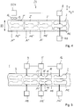
- FIGS. 1 to 7 are initially described together in terms of their similarities. They are a process according to the invention and a novel process Plant for producing a sheet metal blank 2 of flexible rolled strip material 3 shown.
- a starting material hot strip or cold strip made of a metallic material, in particular of a hardenable steel material can be used.
- the material can be present as a slit strip or as a strip with natural edge.
- step S10 the strip material 3 is rolled by means of a rolling unit 1, by means of flexible rolling.
- the strip material 3 which is wound in the initial state on a coil 4 and before the flexible rolling a largely constant sheet thickness over the length, rolled by rollers 5, 6 such that it receives a variable sheet thickness along the rolling direction.
- the process is monitored and controlled, using the data determined by a sheet thickness measurement 7 as an input signal for controlling the rolls 5, 6.
- the strip material 3 in the rolling direction has different thicknesses over the length.
- the strip material 3 is wound up again to the coil 8 after the flexible rolling, so that it can be fed to the next method step.
- a subsequent process step S40 individual sheet metal blanks 2 are cut out of the flexibly rolled strip material 3 by means of a cutting unit 23.
- the cutting unit 23, which may also be referred to as a cutting arrangement, comprises a measuring device 10, an electronic control unit (ECU) and one or more cutting devices 9.
- the sheet metal blanks 2 are cut out of the strip material 3 by a cutting process by means of Cutting device 9 taking into account measured by means of the measuring device 10 sizes.
- the cutting device 9 is designed in particular in the form of a jet cutting device, wherein the separation of the board 2 from the strip material takes place in this case by means of a jet 11.
- a laser beam cutting device can be used, wherein the separation of the board 2 from the strip material by means of one or more laser beam 11 takes place. It is understood, however, that in principle a mechanical cutting device can be used instead of a jet cutting device.
- the measuring device 10 used for this purpose is upstream of the blasting cutting device 9 in the feed direction of the strip material 3.
- the measuring device 10 comprises at least one sensor 12 for detecting a size representing the thickness of the strip material 3 and a sensor 13 for detecting a variable representing the length position of the strip material 3.
- the thickness and length values detected by the sensors 12, 13 are passed on to the electronic control unit (ECU).
- the electronic control unit is used for further processing of the measured thickness and length values and for controlling the jet cutting device 9.
- the measuring is preferably carried out continuously on the unwound from the coil 8 strip material 3.
- Each length position of the strip material 3 is assigned a thickness value, so that the overall thickness profile of the strip is detected over the length.
- the length values and associated thickness values are recorded in the relaxed state of the unwound strip material 3, that is, essentially free of force except for the required feed force.
- the distance L9 between the measuring device 10 and the jet cutting device 9 is greater than twice the length L2 of a sheet metal blank 2 to be cut out.
- the contours of the metal sheets 2 ', 2 ", 2'" to be cut out and the individual band regions 14 ', 14 ", 14 '''each sheet metal plate are in FIG. 2 shown in dashed lines.
- the contour of the straight cut sheet metal blank 2 is shown by a solid line. Due to the given distance L9 between the measuring device 10 and the cutting device 9, the thickness profile of at least two band regions 14 ', 14 "can be recorded and taken into account for defining the contours to be cut the sheet metal blanks 2. Thus, the manufacturing accuracy is increased overall or reduces the reject rate.
- the contour of the cut out of the strip material 3 sheet metal blanks 2 is arbitrary and can be adjusted individually according to the geometric specifications.
- a cut out of the strip material 3 board 2, which can also be referred to as three-dimensional sheet metal blanks (3D-TRB) or contour cut is schematically in FIG. 1 shown.
- the jet cutting device 9 can be moved at least along two or more axes X, Y, Z, namely in the feed direction, in the transverse direction and optionally in the vertical direction of the strip material.
- the jet cutting device 9 along the axis X can be moved independently of the movement along the axis Y and / or the axis Z, which applies analogously to the other axes (Y, Z).
- the strip material 3 can be stretched during the jet cutting in the longitudinal direction L of the strip material. This can be done by means of a front and behind the jet cutting device 9 arranged feed device (not shown). The two feed devices are synchronized so that the intermediate strip material is stretched.
- the cutting out of the sheet metal blanks 2 from the strip material 3 can be carried out continuously or discontinuously.
- the measuring and cutting takes place during the advancing movement of the strip material 3.
- the feed of the strip material in steps, wherein the cutting out of the boards 2 from the strip material 3 takes place with the belt stopped. After cutting out one or more boards, the strip material is advanced to make the next board or boards.
- the contour cuts and the waste material can be separated by a further cutting unit, and the components are transferred to a transport system.
- the transport system makes the boards 2 a stacking system available, which stacks them in customer containers or on pallets.
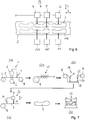
- FIG. 3 shows a cutting unit 23 for performing the method step S40 in a modified embodiment. This corresponds largely to the embodiment according to FIG. 2 , so that reference is made to the above description in terms of similarities. The same details are provided with the same reference numerals, as in FIG. 2 ,
- a difference of the embodiment according to FIG. 3 is that the cutting process takes place in two steps.
- the first cutting process only a part of the contour of the sheet metal blank 2 is cut, so that the blank to be cut remains connected to the remaining edge area of the strip material 3 via a plurality of uncut webs 15, 15 ', 15 ", 15'' the sheet metal blank 2 from the remaining strip material 3 is carried out in the second second step by means of a second cutting device 16.
- the webs 15, 15 ', 15 ", 15''' by means of the further cutting device 16 the first cutting device 9 in the transport direction L of the strip material 3 is downstream, severed.
- a total of four webs are provided, namely a web 15 at the front end, two lateral webs 15 ', 15 "and a web 15''' at the rear end
- the contour and size of the board to be cut may also be provided with any other technically sensible number of webs
- the front web 15 and the lateral web 15 ' have already been severed by means of the second cutting device 16.
- FIG. 4 shows a cutting unit 23 for performing the method step S40 in another embodiment. This corresponds largely to the embodiment according to FIG. 2 , so that reference is made to the above description in terms of similarities. The same details are provided with the same reference numerals, as in FIG. 2 ,
- a difference of the embodiment according to FIG. 4 is that over the width B3 of the strip material 3, two rows of sheet metal blanks 2, 102 are provided, which are to be cut out of the strip material.
- two cutting devices 9, 109 are provided which synchronously each cut an associated sheet metal blank 2, 102 from the strip material. Both cutting devices 9, 109 are controlled by the electronic control unit (ECU) on the basis of the thickness of the strip material 3 detected by the measuring device 10 over the length.
- ECU electronice control unit
- the distance L9 between the measuring device 10 and the jet cutting devices 9, 109 is greater than three times the length L2 of a sheet metal blank 2, which is to be cut out. In this way, in the calculation of the contour position of the sheet metal blanks 2, 102 to be cut out, the sheet thickness profile of respectively three successive blanks 14, 14 ', 14 ", 14''' can be taken into account.
- FIG. 5 shows a cutting unit 23 for performing the method step S40 in another embodiment. This corresponds largely to the embodiment according to FIG. 3 , so that reference is made to the above description in terms of similarities. The same details are provided with the same reference numerals, as in FIG. 3 ,
- a first difference of the embodiment according to FIG. 5 is that over the width B3 of the strip material 3, two rows of sheet metal blanks 2, 102 are provided, which are to be cut out of the strip material.
- two cutting devices 9, 109 are provided which synchronously each cut an associated sheet metal blank 2, 102 from the strip material. Both cutting devices 9, 109 are controlled by the electronic control unit (ECU) on the basis of the thickness of the strip material 3 detected by the measuring device 10 over the length.
- ECU electronice control unit
- the cutting process takes place in two steps.
- first cutting process only part of the contour of the respective sheet metal blank 2, 102 is cut per row of boards, so that the board remains connected to the remaining edge area of the strip material 3 via a plurality of uncut webs 15, 115.
- the complete separation of the sheet metal plate 2, 102 from the remaining strip material 3 is carried out in the second second step by means of the second cutting device 16, 116.
- the webs 15, 115 by means of the further cutting device 16, 116, the first cutting device 9, 109 in the transport direction L. downstream of the strip material 3, cut through.
- the respective contour position for the sheet metal blanks 2, 102 to be worked out from the strip material 3 takes place in each case as a function of the measured thickness over the length of at least two successive blanks.
- FIG. 6 shows a cutting unit 23 for performing the method step S40 in another embodiment. This corresponds largely to the embodiment according to FIG. 5 , so that reference is made to the above description in terms of similarities. The same details are provided with the same reference numerals, as in FIG. 5 ,
- a difference of the embodiment according to FIG. 6 consists in that for carrying out the first substep several cutting devices 9, 9 '; 109, 109 'are provided, with which a sheet metal blank 2, 2'; 102, 102 'are each processed synchronously. This also leads to a reduction of the processing time compared to a design with only one cutting device per board row. For the separation of the webs 15, a cutting device 16, 116 is provided per row.
- FIG. 7 a method according to the invention is shown with further possible method steps, which are each optional.
- the strip material 3 can be smoothed in step S20 by means of a band straightening unit 17. If necessary, the material can also be annealed after the flexible rolling or after smoothing.
- the strip material 3 can be provided with a corrosion protection in method step S30.
- the strip material 3 passes through an electrolytic strip coating unit 18. It can be seen that the strip coating takes place in a continuous process, that is, the strip material 3 is unwound from the coil 4, passes through the coating unit 18 and is wound up again to the coil 4 after coating.
- the coil coating unit 18 includes a dip tank 19 filled with an electrolytic liquid 20 passing through the strip material 3.
- the strip material after the electrolytic coating (S30) is cut according to the method step S40 described above, wherein individual sheet metal blanks 2 are cut out of the strip material. It is understood that the working out of the sheet metal blanks according to each of the embodiments according to the FIGS. 2 to 6 can be made, so that in this regard abbreviated reference is made to the above description.
- the blanks 2 After the production of blanks 2 from the strip material 3, the blanks 2 can be formed into the desired three-dimensional end product in method step S50. After a first possibility, the boards for this hot-formed or, after a second possibility, cold-formed.
- Hot forming can be done as a direct or indirect process.
- the blanks 2 are heated to austenitizing temperature prior to forming, which can be done, for example, by induction or in an oven.
- the heated board is reshaped in a forming tool 24 and simultaneously cooled at a high cooling rate, whereby the component is given its final contour and cured at the same time.
- indirect hot forming the blank 2 is subjected to preforming prior to austenitizing. The preforming takes place in a cold state of the board, that is without prior heating. When preforming the component receives a profile that does not yet correspond to the final shape, but is approximated to this. After preforming, austenitizing and thermoforming then take place, as in the direct process, whereby the component receives its final contour and is hardened.
- the blanks can also be cold formed.
- the cold forming is particularly suitable for soft body steels or components to which there are no special requirements in terms of strength. During cold forming, the blanks are reshaped at room temperature.
- the process control shown can also be modified.
- the electrolytic coating can also be carried out before the flexible rolling or after working out the blanks 2 from the strip material, or after the forming of the molded part by way of piece coating.
Description
- Die Erfindung betrifft ein Verfahren und eine Vorrichtung zur Herstellung von Blechplatinen mit verschiedenen Blechdicken.
- Aus der
DE 10 2012 110 972 B3 ist ein Verfahren zum Herstellen eines Erzeugnisses aus flexibel gewalztem Bandmaterial bekannt. Das flexibel gewalzte Bandmaterial wird anschließend elektrolytisch beschichtet und wärmebehandelt. Aus dem flexibel gewalzten Bandmaterial werden Platinen durch mechanischen Zuschnitt oder Laserschweißen hergestellt. Die so hergestellten Platinen können anschließend im Wege eines Umformverfahrens zu einem Formteil weiterbearbeitet werden, das beispielsweise als Strukturbauteil für ein Kraftfahrzeug gestaltet sein kann. - Aus der
DE 10 2012 014 258 A1 ist ein Verfahren zur Herstellung eines Bauteils aus Stahl mit verminderter Kantenrissempfindlichkeit bekannt. Das Bauteil wird durch Umformen einer Blechplatine aus Stahl hergestellt, bei dem die Platine zuvor aus einem Bandmaterial zugeschnitten und anschließend zu einem Bauteil umgeformt wird. Der Zuschnitt der Platine erfolgt bei einer Temperatur oberhalb der Raumtemperatur und unterhalb der Ac1-Umwandlungstemperatur. Die Platine kann flexibel mit unterschiedlichen Dicken gewalzt sein. - Aus der
WO 2010/085486 A1 ist ein Verfahren und eine Anlage zum Laserschneiden von Platinen aus einem Stahlband bekannt. - Aus der
EP 2 420 344 B1 ist ein Verfahren zum Herstellen eines Konturschnitts aus einem Blechband bekannt. Das Blechband wird bezüglich seiner Breite in mindestens drei Bearbeitungsstreifen gegliedert, wobei jedem Bearbeitungsstreifen eine Laserschneideinrichtung zugeordnet ist. Der Arbeitsbereich der ersten Laserschneideinrichtung schließt sich gegenüber dem Arbeitsbereich der zweiten Laserschneideinrichtung stromauf- oder stromabwärts an. Die Laserschneideinrichtungen werden so gesteuert, dass ein erster Teilabschnitt des Konturschnitts mittels der stromaufwärtigen Laserschneideinrichtung hergestellt wird und ein zweiter Teilabschnitt zur Fertigstellung des Konturschnitts von der stromabwärtigen Laserschneideinrichtung. - Der vorliegenden Erfindung liegt die Aufgabe zugrunde, ein Verfahren zur Herstellung von Blechplatinen mit verschiedenen Blechdicken vorzuschlagen, das eine große Prozessstabilität bietet und eine hohe Fertigungsgenauigkeit der herzustellenden Blechplatinen beziehungsweise eine geringe Ausschussrate gewährleistet. Die Aufgabe besteht ferner darin, eine entsprechende Anlage vorzuschlagen, mit der Blechplatinen prozesssicher und mit hoher Genauigkeit hergestellt werden können.
- Eine Lösung besteht in einem Verfahren zur Herstellung einer Blechplatine, mit den Schritten: Flexibles Walzen eines Bandmaterials aus einem metallischen Werkstoff, wobei ein Dickenprofil mit unterschiedlichen Blechdicken über der Länge des Bandmaterials erzeugt wird, derart, dass hintereinanderliegende Bereiche des flexibel gewalzten Bandmaterials jeweils mit einem Solldickenprofil einer hieraus auszuschneidenden Blechplatine korrespondieren; Ermitteln eines Messdickenprofils von mehreren hintereinander liegenden Bereichen des Bandmaterials; Berechnen einer Sollposition in dem Bandmaterial für eine aus dem Bandmaterial auszuschneidende Blechplatine in Abhängigkeit von dem generierten Messdickenprofil von zumindest zwei hintereinander liegenden Bereichen des Bandmaterials; Schneiden des flexibel gewalzten Bandmaterials mittels zumindest einer Schneidvorrichtung entlang der Sollposition zum Erzeugen der Blechplatine.
- Ein Vorteil besteht darin, dass eine genaue Zuordnung der Sollkonturlage für die aus dem Bandmaterial auszuschneidende Blechplatine auf das gemessene Blechdickenprofil des Bandmaterials erfolgen kann. Auf diese Weise wird eine hohe Fertigungsgenauigkeit der herzustellenden Blechplatinen erreicht, beziehungsweise der Anteil von aufgrund von Fertigungsungenauigkeiten nicht brauchbarem Ausschuss wird reduziert. Durch das dem Strahlschneidprozess vorgelagerte Vermessen des Bandmaterials können gegebenenfalls Bereiche der Platine, die hinsichtlich des Dickenverlaufs nicht den geometrischen Vorgaben entsprechen, unbearbeitet gelassen werden. Hierdurch ergibt sich eine besonders hohe Effizienz des Verfahrens, da kein unnötiger Ausschuss erzeugt wird.
- Als Ausgangsmaterial für das Flexible Walzen wird Bandmaterial aus einem metallischen Werkstoff verwendet. Hiermit sind insbesondere Werkstoffe gemeint, die zumindest ein metallisches Element beziehungsweise eine Legierung aus metallischen Elementen beinhalten. In der industriellen Fertigung wird häufig Bandmaterial aus Stahl beziehungsweise aus einer Stahllegierung verwendet, wobei auch Bandmaterial aus anderen Metallen, wie Aluminium beziehungsweise Aluminiumlegierungen eingesetzt werden. Es kann Warmband oder Kaltband verwendet werden, wobei diese Begriffe im Sinne der Fachsprache für unterschiedliche Bandbreitenbereiche zu verstehen sind. Unter Warmband wird ein Walzstahlfertigerzeugnis (Stahlband) verstanden, das durch Walzen nach vorherigem Erwärmen erzeugt wird. Mit Kaltband ist ein kaltgewalztes Stahlband (Flachstahl) gemeint. Als kaltgewalzt wird Flachstahl bezeichnet, dessen letzte Dickenabnahme durch Walzen ohne vorhergehendes Erwärmen erfolgt.
- Das Bandmaterial mit im Wesentlichen einheitlicher Blechdicke wird im Rahmen des Flexiblen Walzens durch Verändern des Walzspalts zu Bandmaterial mit variabler Blechdicke über der Länge ausgewalzt. Dabei wird das Bandmaterial derart gewalzt, dass bereichsweise erzeugte Dickenprofile des Bandmaterials jeweils zu einem Solldickenprofil einer hieraus herzustellenden Platine korrespondieren. Hiermit ist insbesondere gemeint, dass ein in einem Bereich durch Flexibles Walzen erzeugtes Dickenprofil dem Solldickenprofil der hieraus auszuschneidenden Platinen zumindest im Wesentlichen entspricht, das heißt unter Berücksichtigung von Fertigungs- und Lagetoleranzen. Im Rahmen der vorliegenden Offenbarung ist mit einem Bereich des Bandmaterials ein geometrisch definierbarer Teil des Bandmaterials gemeint, aus dem eine zugehörige Platine ausgeschnitten wird. Die einzelnen Bereiche sind hintereinander im Bandmaterial angeordnet. Es ist insbesondere vorgesehen, dass die einzelnen Bereiche des Bandmaterials jeweils mehrere Abschnitte mit unterschiedlicher Dicke haben. Diese durch das Flexible Walzen erzeugten Abschnitte unterschiedlicher Dicke erstrecken sich quer zur Längsrichtung beziehungsweise zur Walzrichtung des Bandmaterials. Das Bandmaterial kann nach dem Flexiblen Walzen auf einfache Weise wieder zum Coil aufgewickelt werden und an anderer Stelle der Weiterverarbeitung zugeführt werden, oder es kann direkt weiterverarbeitet werden.
- Das Ermitteln eines Dickenprofils erfolgt insbesondere auf Basis von Messungen der Dicke über der Länge des Bandmaterials. Einer gemessenen Längenposition beziehungsweise Wegposition des Bandmaterials wird eine zugehörige Dickenposition zugeordnet, welche ein Positionspaar bilden. Zur Messung können ein Dickensensor und ein Wegsensor verwendet werden. Das Messen der Dicke über der Länge des Bandmaterials kann inkrementell, das heißt in Schritten, oder fortlaufend erfolgen. Beim schrittweisen Messen werden je auszuschneidender Blechplatine mehrere Positionen entlang der Längsrichtung gemessen. Aus den gemessenen Dicken- und zugehörigen Positionswerten wird dann das Messdickenprofil generiert. Eine besonders hohe Prozesssicherheit und genaue Fertigung wird durch kontinuierliches Erfassen der Dicke über der Länge des Bandmaterials erreicht. Dabei wird fortlaufend jeder Längenposition des Bandmaterials eine Dickenposition zugeordnet, so dass für einen vermessenen Bandbereich ein vollständiges Messdickenprofil über der Länge vorliegt. Dieses gemessene Dickenprofil kann dann rechnerisch mit dem Solldickenprofil der auszuschneidenden Blechplatine abgeglichen werden, so dass die Lage des anzusetzenden Strahlschnitts individuell an die geometrischen Rahmenbedingungen angepasst werden kann. Die Positionierung beziehungsweise Synchronisierung der Konturlage der aus dem Band auszuschneidenden Platinen zum gegebenen Blechdickenprofil kann mittels geeigneter Berechnungsalgorithmen erfolgen. Auf diese Weise kann eine Lageoptimierung der Bauteile im Band erfolgen, was zu einem stabilen Prozess mit hoher Fertigungsgenauigkeit führt.
- In beispielhafter Konkretisierung kann die Dicke über der Länge des Bandmaterials in einem ersten und einen hieran anschließenden zweiten Bereich des Bandmaterials erfasst werden und das Schneiden der ersten Blechplatine aus dem ersten Bereich in Abhängigkeit von dem Messdickenprofil des ersten und des zweiten Bereichs erfolgen.
- Dieses Prinzip lässt sich in allgemeiner Form weiter fortsetzen. So können auch die Messwerte von mehr als zwei Platinen-Bereichen des Bandmaterials bei der Festlegung der Schnittkontur der Schneidvorrichtung herangezogen werden. Beispielsweise können die Schnittkonturen von aufeinanderfolgenden Gruppen von Platinen, beispielsweise von drei Platinen, unter Berücksichtigung des Messdickenprofils von allen zu dieser Gruppe zugehörigen Bandbereichen bestimmt werden.
- Zum Schneiden einer Platine aus dem Bandmaterial können eine oder mehrere Schneidvorrichtungen verwendet werden. Bei Verwendung mehrerer Schneidvorrichtungen können diese parallel zueinander, das heißt in Bezug auf die Bandbreite nebeneinander, und/oder hintereinander, das heißt in Bezug auf die Bandlängserstreckung hintereinander angeordnet sein. Zumindest ein Teilschnitt zum Trennen einer Platine aus dem Bandmaterial kann mittels eines Strahls erfolgen. In diesem Fall ist zumindest eine der Schneidvorrichtungen als Strahlschneidvorrichtung gestaltet. Es ist aber auch denkbar, dass zumindest ein Teilschnitt zum Trennen einer Platine aus dem Bandmaterial mechanisch mittels eines Stanz- oder Schneidwerkzeugs mit definierter Schneide erfolgt.
- Nach einer möglichen Verfahrensführung wird das Bandmaterial während des Strahlschneidens in Längsrichtung des Bandmaterials gespannt. Durch diese Maßnahme wird eine hohe Lagegenauigkeit des Bandmaterials und damit hohe Fertigungsgenauigkeit der hieraus auszuschneidenden Blechplatinen erreicht.
- Nach einer Ausgestaltung kann die zumindest eine Strahlschneidvorrichtung entlang mehrerer Achsen bewegt werden, wobei insbesondere vorgesehen ist, dass die Bewegung entlang einer Achse unabhängig von der Bewegung einer anderen Achse steuerbar ist. Auf diese Weise wird eine genaue Positionierung und hohe Fertigungsgenauigkeit erreicht.
- Es können mehrere Schneidvorrichtungen zum Strahlschneiden beziehungsweise mechanischen Schneiden der Blechplatinen aus dem Bandmaterial vorgesehen sein. Dabei können mehrere Schneidvorrichtungen gleichzeitig an dem Konturschnitt derselben Blechplatine arbeiten, oder es können mehrere Blechplatinen gleichzeitig mittels einer jeweils zugehörigen Schneidvorrichtung bearbeitet werden.
- Das Verfahren kann kontinuierlich durchgeführt werden, das heißt, dass das Strahlschneiden unter Vorschub des Bandmaterials durchgeführt wird. In diesem Fall bewegen sich die Schneidvorrichtungen mit dem Bandmaterial mit. Alternativ kann das Verfahren auch diskontinuierlich durchgeführt werden, das heißt, es erfolgt ein Vorschub des zu schneidenden Bandbereichs zur Schneidvorrichtung, dann wird der Vorschub gestoppt, und das Schneiden der Blechplatine aus dem Bandmaterial erfolgt bei stillstehendem Band. Nach dem Herausschneiden der Blechplatine wird das Bandmaterial zur Herstellung der nächsten Platine vorgeschoben. Letztere Verfahrensführung eignet sich insbesondere für ein mechanisches Schneiden.
- Nach einer möglichen Ausgestaltung kann das Strahlschneiden derart durchgeführt werden, dass eine strahlgeschnittene Platine mittels zumindest einem Steg zunächst mit dem Bandmaterial verbunden bleibt. Das vollständige Trennen der Blechplatine vom verbleibenden Bandmaterial kann anschließend in einem nachgelagerten Schritt durchgeführt werden. Dabei wird der zumindest eine Steg mittels einer weiteren Schneidvorrichtung, die der ersten Schneidvorrichtung in Transportrichtung des Bandmaterials nachgelagert ist, durchtrennt. In Konkretisierung kann das Strahlschneiden derart durchgeführt werden, dass im Rahmen der ersten Schneidbearbeitung mehrere Stege vorgesehen werden, über welche die teilgeschnittene Platine mit dem Bandmaterial zunächst verbunden bleibt. Dabei ist es günstig, wenn zumindest ein erster Steg in einem in Bezug auf die Bandvorschubrichtung vorderen ersten Drittel der strahlgeschnittenen Platine angeordnet ist und zumindest ein zweiter Steg in einem in Bezug auf die Bandvorschubrichtung hinteren Drittel der Strahlgeschnittenen Platine angeordnet ist. Auf diese Weise können Vorschubkräfte vom Bandmaterial auf die teilbeschnittene Platine übertragen werden, so dass die Platine genau positioniert ist. Der erste Steg und/oder der zweite Steg können so gestaltet sein, dass sie sich im Wesentlichen in Längsrichtung des Bandmaterials erstrecken.
- Nach einer möglichen Konkretisierung kann zum Strahlschneiden ein Laserstrahl verwendet werden, das heißt die Strahlschneidevorrichtung ist in Form einer Laserstrahlschneidevorrichtung gestaltet. Es versteht sich jedoch, dass auch andere Strahlschneideverfahren einsetzbar sind, wie beispielsweise Wasserstrahlschneiden. Mit der Strahlschneidvorrichtung können Schneidparameter eingestellt und/oder während des Schneidprozesses gesteuert werden. Solche den Schneidprozess beeinflussende Schneidparameter sind beispielsweise Strahlleistung, Fokus des Strahls, Vorschubgeschwindigkeit, Ausgasdrücke und/oder andere technische Parameter. Insbesondere kann vorgesehen sein, dass zumindest einer der Schneidparameter der Strahlschneidvorrichtung auf die Blechdicke und/oder die Materialeigenschaften des metallischen Werkstoffs eingestellt wird beziehungsweise während des Schneidprozesses in Abhängigkeit von den gemessenen Blechdicken des Bandmaterials gesteuert wird. Beispielsweise können dickere Bandabschnitte mit anderen Parametern beschnitten werden als dünnere Bandabschnitte, so dass der Schneidprozess insgesamt effizient und bedarfsgerecht durchgeführt werden kann. Dies gilt selbstverständlich auch für mechanisches Schneiden der Platinen, bei dem das mechanische Schneiden beeinflussende Schneidparameter, wie beispielsweise Schneidkraft oder Schnittgeschwindigkeit, in Abhängigkeit von der Blechdicke gesteuert werden können.
- Es können weitere Verfahrensschritte vorgesehen sein, wie das Aufbringen eines Korrosionsschutzes auf die Blechplatinen beziehungsweise das Bandmaterial. Nach einer ersten Möglichkeit kann das Bandmaterial bereits vor dem Flexiblen Walzen beschichtet werden, was jedoch zur Folge hat, dass die Korrosionsschutzschicht aufgrund des nachfolgenden Flexiblen Walzens über der Länge des Bandmaterials eine unterschiedliche Dicke erhält. Nach einer zweiten Möglichkeit kann die Korrosionsschutzschicht auch nach dem Flexiblen Walzen aufgebracht werden. In diesem Fall ist die Dicke der Korrosionsschutzschicht über der Länge des flexibel gewalzten Bandes im Wesentlichen konstant. In beiden Fällen wird der Korrosionsschutz vorzugsweise im Durchlaufverfahren aufgebracht. Hierfür wird das Bandmaterial vom Coil abgewickelt, im Durchlaufverfahren mit Korrosionsschutz versehen, und anschließend wieder zum Coil aufgewickelt, um dem jeweils nachfolgenden Verfahrensschritten zugeführt zu werden. Es versteht sich, dass das Bandmaterial auch direkt weiterbearbeitet werden kann, das heißt in abgewickeltem Zustand. Nach einer weiteren Möglichkeit können auch zunächst die Blechplatinen aus dem Bandmaterial herausgearbeitet und anschließend stückweise mit Korrosionsschutz versehen werden.
- Die Blechplatinen können in nachfolgenden Fertigungsschritten weiterbearbeitet werden, beispielsweise zu einem Formteil umgeformt werden. Die Formteile können gehärtet werden. Alternativ können die Blechplatinen im Wege des Presshärtens auch in einem Werkzeug umgeformt und gehärtet werden.
- Die Lösung der oben genannte Aufgabe besteht weiter in einer Anlage zur Herstellung einer Blechplatine, umfassend: eine Walzeinheit zum Flexiblen Walzen von Bandmaterial aus einem metallischen Werkstoff, insbesondere Stahlblech, und eine Schneideinheit zum Ausschneiden von einzelnen Blechplatinen aus dem Bandmaterial, wobei das Bandmaterial eine Vielzahl von hintereinander liegenden Bereichen aufweist, aus denen jeweils eine Blechplatine auszuschneiden ist; wobei die Schneideinheit eine Messvorrichtung zum Erfassen der Dicke des Bandmaterials in Längsrichtung des Bandmaterials, zumindest eine Schneidvorrichtung zum Schneiden des flexibel gewalzten Bandmaterials, und eine elektronische Steuereinheit zum Steuern der Schneidvorrichtung auf Basis von mittels der Messvorrichtung erfassten Messwerten aufweist, dadurch gekennzeichnet, dass im Betrieb der Abstand zwischen der Messvorrichtung und der Schneidvorrichtung größer als das Doppelte der Länge einer auszuschneidenden Blechplatine ist, so dass eine Sollposition für eine aus dem Bandmaterial herauszuarbeitende Blechplatine in Abhängigkeit von einem Messprofil von zumindest zwei hintereinander liegenden Bereichen des Bandmaterials bestimmbar ist. Die Anlage eignet sich somit zur Durchführung des oben genannten Verfahrens. Es ergeben sich insofern auch dieselben Vorteile, so dass diesbezüglich auf die obige Beschreibung Bezug genommen wird. Es versteht sich, dass alle verfahrensmäßigen Merkmale auf die Anlage übertragbar sind, und umgekehrt, alle anlagenbezogenen Merkmale auf das Verfahren. Die Anlage ermöglicht eine Lageoptimierung der auszuschneidenden Blechplatinen im Bandmaterial, das heißt eine genaue positionsmäßige Einstellung der Sollkontur der aus dem Bandmaterial auszuschneidenden Blechplatine relativ zum Blechdickenprofil des Bandmaterials. Die Sollkontur der auszuschneidenden Blechplatinen wird erst nach der Vermessung der Blechdicke über der Länge festgelegt, so dass insgesamt eine hohe Fertigungsgenauigkeit erreicht wird.
- Vorzugsweise umfasst die Schneidvorrichtung zumindest eine Strahlschneidvorrichtung, wobei es sich versteht, dass in Ergänzung oder alternativ auch zumindest eine mechanische Schneidvorrichtung vorgesehen sein kann. Nach einer möglichen Konkretisierung können mehrere Strahlschneidevorrichtungen vorgesehen sein. Die Strahlschneidevorrichtungen können derart gestaltet und von der elektronischen Steuereinheit ansteuerbar sein, dass mehrere Blechplatinen gleichzeitig aus dem Bandmaterial ausgeschnitten werden können. Alternativ oder in Ergänzung können auch mehrere Schneidvorrichtungen vorgesehen sein, die gleichzeitig eine Blechplatine ausschneiden.
- Nach einer weiteren Ausgestaltung kann eine Vorschubanordnung zum Vorschub des Bandmaterials vorgesehen sein. Die Vorschubanordnung kann eine erste Vorschubvorrichtung aufweisen, die vor der Schneidvorrichtung angeordnet ist, und eine zweite Vorschubvorrichtung, die hinter der Schneidvorrichtung angeordnet ist. Die Vorschubanordnung ist vorzugsweise so steuerbar, dass das Bandmaterial im Bereich des Schneidens gespannt ist.
- Die Schneideanlage beziehungsweise das Verfahren zum Ausschneiden kann in weiterer Konkretisierung folgende Merkmale umfassen: Das Coil kann von einem Coilladestuhl, einer Vorrichtung zum Zwischenlagern des Coils, einer Haspel zugeführt werden. Mittels der Haspel wird das Coil abgehaspelt und der Endabschnitt des Coils wird mit entsprechenden Hilfsmitteln an der Richteinheit eingeführt und gemäß den Vorgaben gerichtet. Es kann ein Bandspeicher vorgesehen sein, der Toleranzen und Schwankungen im Bearbeitungsprozess ausgleicht. Hierfür ist der Bandspeicher so ausreichend dimensioniert, das die maximalen Vorschublängen und Geschwindigkeiten bei der Bearbeitung voll abgedeckt werden. Zwischen dem Bandspeicher und der Messvorrichtung kann eine Bandberuhigungsvorrichtung vorgesehen sein, in der das Bandmaterial beruhigt beziehungsweise geglättet wird. Die Messvorrichtung umfasst eine Banddickenmessung und eine Bandlängenmessung. Der Vorschub des Bandmaterials erfolgt mittels einer Vorschubvorrichtung, die der Messvorrichtung vorgelagert ist. Die Zuführung beziehungsweises der Vorschub sind so gestaltet, dass im laufenden Betrieb Längentoleranzen aus dem Walzprozess ausgeglichen werden können. An den ersten Vorschub schließt sich ein Rollengang an, der zumindest die Doppelte Länge eines Platinenbereichs aufweist, um die erforderliche Messlänge zur Blechdickenmessung und Zuordnung der Konturlage mehrerer Platinen relativ zum Blechdickenprofil zu erzielen. Im Anschluss werden die Konturlagen im Band positioniert und die Position an die Schneidvorrichtung übermittelt. Es ist insbesondere vorgesehen, dass die Messung der Dicke und Längenwerte fortlaufend erfolgt und unmittelbar an die Steuerung der Schneidvorrichtung zum exakten Positionieren und Steuern der Schneidwerkzeuge weitergegeben wird. Es findet also eine fortlaufende Kontrolle statt, bei der die vollständige Bandlänge vermessen wird.
- Bevorzugte Ausführungsbeispiele werden nachstehend anhand der Zeichnungsfiguren erläutert. Hierin zeigt
- Figur 1
- ein erfindungsgemäßes Verfahren schematisch als Ablaufdiagramm;
- Figur 2
- die Schneideanordnung aus
Figur 1 schematisch als Detail; - Figur 3
- die Schneideanordnung aus
Figur 1 schematisch als Detail in einer abgewandelten Ausführungsform; - Figur 4
- die Schneideanordnung aus
Figur 1 schematisch als Detail in einer weiteren Ausführungsform; - Figur 5
- die Schneideanordnung aus
Figur 1 schematisch als Detail in einer weiteren Ausführungsform; - Figur 6
- die Schneideanordnung aus
Figur 1 schematisch als Detail in einer weiteren Ausführungsform; und - Figur 7
- das Verfahren nach
Figur 1 schematisch als Ablaufdiagramm mit weiteren Verfahrensschritten. - Die
Figuren 1 bis 7 werden hinsichtlich ihrer Gemeinsamkeiten zunächst gemeinsam beschrieben. Es sind ein erfindungsgemäßes Verfahren sowie eine erfindungsgemäße Anlage zur Herstellung einer Blechplatine 2 aus flexibel gewalztem Bandmaterial 3 gezeigt. Als Ausgangsmaterial kann Warmband oder Kaltband aus einem metallischen Werkstoff, insbesondere aus einem härtbaren Stahlwerkstoff verwendet werden. Das Material kann als Spaltband oder als Band mit Naturkante vorliegen. - Im Verfahrensschritt S10 wird das Bandmaterial 3 mittels einer Walzeinheit 1 walzend bearbeitet, und zwar mittels flexiblem Walzen. Hierfür wird das Bandmaterial 3, das im Ausgangszustand auf einem Coil 4 aufgewickelt ist und vor dem flexiblen Walzen eine weitestgehend konstante Blechdicke über der Länge aufweist, mittels Walzen 5, 6 derart gewalzt, dass es längs der Walzrichtung eine variable Blechdicke erhält. Während des Walzens wird der Prozess überwacht und gesteuert, wobei die von einer Blechdickenmessung 7 ermittelten Daten als Eingangssignal zur Steuerung der Walzen 5, 6 verwendet werden. Nach dem flexiblen Walzen hat das Bandmaterial 3 in Walzrichtung unterschiedliche Dicken über der Länge. Das Bandmaterial 3 wird nach dem flexiblen Walzen wieder zum Coil 8 aufgewickelt, so dass es dem nächsten Verfahrensschritt zugeführt werden kann.
- In einem nachgelagerten Verfahrensschritt S40 werden mittels einer Schneideeinheit 23 einzelne Blechplatinen 2 aus dem flexibel gewalzten Bandmaterial 3 ausgeschnitten. Die Schneideinheit 23, die auch als Schneidanordnung bezeichnet werden kann, umfasst eine Messvorrichtung 10, eine elektronische Regeleinheit (Electronic Control Unit, ECU) sowie eine oder mehrere Schneidvorrichtungen 9. Dabei erfolgt das Ausschneiden der Blechplatinen 2 aus dem Bandmaterial 3 durch einen Schneidprozess mittels der Schneidvorrichtung 9 unter Berücksichtigung von mittels der Messvorrichtung 10 gemessenen Größen. Die Schneidvorrichtung 9 ist insbesondere in Form einer Strahlschneidvorrichtung gestaltet, wobei das Heraustrennen der Platine 2 aus dem Bandmaterial in diesem Fall mittels eines Strahls 11 erfolgt. In Konkretisierung kann eine Laserstrahlschneidvorrichtung verwendet werden, wobei das Heraustrennen der Platine 2 aus dem Bandmaterial mittels eines oder mehrerer Laserstrahlens 11 erfolgt. Es versteht sich jedoch, dass grundsätzlich auch eine mechanische Schneidvorrichtung anstelle einer Strahlschneidvorrichtung zum Einsatz kommen kann.
- Ein wichtiger Teilschritt zum Ausschneiden der Blechplatinen 2 ist das Messen der Dicke entlang der Länge des Bandmaterials 3. Die hierfür verwendete Messvorrichtung 10 ist der Strahlschneidvorrichtung 9 in Vorschubrichtung des Bandmaterials 3 vorgelagert. Die Messvorrichtung 10 umfasst zumindest einen Sensor 12 zum Erfassen einer die Dicke des Bandmaterials 3 repräsentierenden Größe und einen Sensor 13 zum Erfassen einer die Längenposition des Bandmaterials 3 repräsentierenden Größe. Die von den Sensoren 12, 13 erfassten Dicken- und Längenwerte werden an die elektronische Regeleinheit (ECU) weitergegeben. Die elektronische Regeleinheit dient zur Weiterverarbeitung der gemessenen Dicken- und Längenwerte sowie zur Steuerung der Strahlschneidevorrichtung 9. Das Messen erfolgt vorzugsweise kontinuierlich am vom Coil 8 abgewickelten Bandmaterial 3. Dabei wird jeder Längenposition des Bandmaterials 3 ein Dickenwert zugeordnet, so dass insgesamt das Dickenprofil des Bandes über der Länge erfasst wird. Die Längenwerte und zugehörigen Dickenwerte werden in entspanntem Zustand des abgewickelten Bandmaterials 3 erfasst, das heißt bis auf die erforderliche Vorschubkraft im Wesentlichen kraftfrei.
- Wie insbesondere in
Figur 2 erkennbar, ist der Abstand L9 zwischen der Messvorrichtung 10 und der Strahlschneidvorrichtung 9 größer als das Doppelte der Länge L2 einer auszuschneidenden Blechplatine 2. Die Konturen der noch auszuschneidenden Blechplatinen 2', 2", 2''' sowie die einzelnen Bandbereiche 14', 14", 14''' je Blechplatine sind inFigur 2 gestrichelt dargestellt. Die Kontur der gerade geschnittenen Blechplatine 2 ist mit durchgezogener Linie dargestellt. Durch den gegebenen Abstand L9 zwischen Messvorrichtung 10 und Schneidvorrichtung 9 kann das Dickenprofil von mindestens zwei Bandbereichen 14', 14" erfasst und für die Festlegung der zu schneidenden Konturen berücksichtigt werden. Auf diese Weise können Längentoleranzen des flexibel gewalzten Bandmaterials 3 ausgeglichen und bei der Herstellung der Blechplatinen 2 berücksichtigt werden. Damit wird die Fertigungsgenauigkeit insgesamt gesteigert beziehungsweise die Ausschussrate vermindert. - Die Kontur der aus dem Bandmaterial 3 auszuschneidenden Blechplatinen 2 ist beliebig und kann entsprechend den geometrischen Vorgaben individuell eingestellt werden. Eine aus dem Bandmaterial 3 ausgeschnittene Platine 2, die auch als dreidimensionale Blechplatinen (3D-TRB) oder Konturschnitt bezeichnet werden können, ist schematisch in
Figur 1 gezeigt. Um beliebige Konturen herzustellen, kann die Strahlschneidvorrichtung 9 zumindest entlang zweier oder mehr Achsen X, Y, Z, nämlich in Vorschubrichtung, in Querrichtung und gegebenenfalls in Hochrichtung des Bandmaterials bewegt werden. Dabei kann die Strahlschneidvorrichtung 9 entlang der Achse X unabhängig von der Bewegung entlang der Achse Y und/oder der Achse Z bewegt werden, was analog für die übrigen Achsen (Y, Z) gilt. - Für eine hohe Lagegenauigkeit der auszuschneidenden Platine 2 kann das Bandmaterial 3 während des Strahlschneidens in Längsrichtung L des Bandmaterials gespannt werden. Dies kann mittels einer vor und einer hinter der Strahlschneidvorrichtung 9 angeordneten Vorschubeinrichtung (nicht dargestellt) erfolgen. Die beiden Vorschubeinrichtungen sind dabei so synchronisiert, dass das dazwischenliegende Bandmaterial gespannt ist.
- Das Ausschneiden der Blechplatinen 2 aus dem Bandmaterial 3 kann kontinuierlich oder diskontinuierlich durchgeführt werden. Beim kontinuierlichen Prozess erfolgt das Messen und Schneiden während der Vorschubbewegung des Bandmaterials 3. Beim diskontinuierlichen Prozess erfolgt der Vorschub des Bandmaterials in Schritten, wobei das Ausschneiden der Platinen 2 aus dem Bandmaterial 3 bei stillstehendem Band erfolgt. Nach dem Ausschneiden einer oder mehrerer Platinen wird das Bandmaterial zur Herstellung der nächsten Platine beziehungsweise Platinen vorgeschoben.
- Hinter der letzten Vorschubeinrichtung können die Konturschnitte und die Materialabfälle durch eine weitere Schneideinheit getrennt, und die Bauteile an ein Transportsystem übergeben werden. Das Transportsystem stellt die Platinen 2 einem Stapelsystem zur Verfügung, welche diese in Kundenbehälter oder auf Paletten stapelt.
-
Figur 3 zeigt eine Schneideinheit 23 zur Durchführung des Verfahrensschritts S40 in einer abgewandelten Ausführungsform. Diese entspricht weitestgehend der Ausführungsform gemäßFigur 2 , so dass hinsichtlich der Gemeinsamkeiten auf die obige Beschreibung Bezug genommen wird. Dabei sind gleiche Einzelheiten mit gleichen Bezugszeichen versehen, wie inFigur 2 . - Ein Unterschied der Ausführungsform gemäß
Figur 3 besteht darin, dass der Schneidprozess in zwei Teilschritten erfolgt. Im Rahmen des ersten Schneidprozesses wird nur ein Teil der Kontur der Blechplatine 2 geschnitten, so dass die auszuschneidende Platine über mehrere unbeschnittene Stege 15, 15', 15", 15''' mit dem verbleibenden Randbereich des Bandmaterials 3 verbunden bleiben. Das vollständige Trennen der Blechplatine 2 vom verbleibenden Bandmaterial 3 erfolgt im nachgelagerten zweiten Teilschritt mittels einer zweiten Schneidvorrichtung 16. Dabei werden die Stege 15, 15', 15", 15''' mittels der weiteren Schneidvorrichtung 16, die der ersten Schneidvorrichtung 9 in Transportrichtung L des Bandmaterials 3 nachgelagert ist, durchtrennt. InFigur 3 ist erkennbar, dass bei der vorliegenden Ausführung insgesamt vier Stege vorgesehen sind, und zwar einer Steg 15 am vorderen Ende, zwei seitliche Stege 15', 15" und ein Steg 15''' am hinteren Ende. Es versteht sich jedoch, dass je nach Kontur und Größe der zu schneidenden Platine auch eine beliebige andere technisch sinnvolle Zahl von Stegen vorgesehen sein kann. In dem gezeigten Zustand des zweiten Teilschritts sind der vordere Steg 15 und der seitliche Steg 15' mittels der zweiten Schneidvorrichtung 16 bereits durchtrennt worden. -
Figur 4 zeigt eine Schneideinheit 23 zur Durchführung des Verfahrensschritts S40 in einer weiteren Ausführungsform. Diese entspricht weitestgehend der Ausführungsform gemäßFigur 2 , so dass hinsichtlich der Gemeinsamkeiten auf die obige Beschreibung Bezug genommen wird. Dabei sind gleiche Einzelheiten mit gleichen Bezugszeichen versehen, wie inFigur 2 . - Ein Unterschied der Ausführungsform gemäß
Figur 4 besteht darin, dass über der Breite B3 des Bandmaterials 3 zwei Reihen von Blechplatinen 2, 102 vorgesehen sind, die aus dem Bandmaterial auszuschneiden sind. Entsprechend sind auch zwei Schneidvorrichtungen 9, 109 vorgesehen, die synchron jeweils eine zugehörige Blechplatine 2, 102 aus dem Bandmaterial ausschneiden. Beide Schneidvorrichtungen 9, 109 werden von der elektronischen Regeleinheit (ECU) auf Basis der von der Messvorrichtung 10 über der Länge erfassten Dicke des Bandmaterials 3 gesteuert. - Bei der vorliegenden Ausführungsform ist ebenfalls vorgesehen, dass die jeweilige Konturlage für die aus dem Bandmaterial 3 herauszuarbeitenden Blechplatinen 2, 102 jeweils in Abhängigkeit von dem gemessenen Dickenverlauf über der Länge von mindestens zwei aufeinander folgenden Platinenbereichen erfolgt. Konkret ist hier vorgesehen, dass der Abstand L9 zwischen der Messvorrichtung 10 und den Strahlschneidvorrichtungen 9, 109 größer als das Dreifache der Länge L2 einer auszuschneidenden Blechplatine 2, 102 ist. Auf diese Weise kann bei der Berechnung der Konturlage der auszuschneidenden Blechplatinen 2, 102 der Blechdickenverlauf von jeweils drei aufeinanderfolgenden Platinenbereichen 14, 14', 14", 14''' berücksichtigt werden.
-
Figur 5 zeigt eine Schneideinheit 23 zur Durchführung des Verfahrensschritts S40 in einer weiteren Ausführungsform. Diese entspricht weitestgehend der Ausführungsform gemäßFigur 3 , so dass hinsichtlich der Gemeinsamkeiten auf die obige Beschreibung Bezug genommen wird. Dabei sind gleiche Einzelheiten mit gleichen Bezugszeichen versehen, wie inFigur 3 . - Ein erster Unterschied der Ausführungsform gemäß
Figur 5 besteht darin, dass über der Breite B3 des Bandmaterials 3 zwei Reihen von Blechplatinen 2, 102 vorgesehen sind, die aus dem Bandmaterial auszuschneiden sind. Entsprechend sind auch zwei Schneidvorrichtungen 9, 109 vorgesehen, die synchron jeweils eine zugehörige Blechplatine 2, 102 aus dem Bandmaterial ausschneiden. Beide Schneidvorrichtungen 9, 109 werden von der elektronischen Regeleinheit (ECU) auf Basis der von der Messvorrichtung 10 über der Länge erfassten Dicke des Bandmaterials 3 gesteuert. Die Messvorrichtung ist vorliegend der Einfachheit halber nicht gezeigt. - Ein weiterer Unterschied besteht darin, dass der Schneidprozess in zwei Teilschritten erfolgt. Im Rahmen des ersten Schneidprozesses werden je Platinenreihe nur ein Teil der Kontur der jeweiligen Blechplatine 2, 102 geschnitten, so dass die Platine über mehrere unbeschnittene Stege 15, 115 mit dem verbleibenden Randbereich des Bandmaterials 3 verbunden bleiben. Das vollständige Trennen der Blechplatine 2, 102 vom verbleibenden Bandmaterial 3 erfolgt im nachgelagerten zweiten Teilschritt mittels der zweiten Schneidvorrichtung 16, 116. Dabei werden die Stege 15, 115 mittels der weiteren Schneidvorrichtung 16, 116, die der ersten Schneidvorrichtung 9, 109 in Transportrichtung L des Bandmaterials 3 nachgelagert ist, durchtrennt.
- Es ist ferner vorgesehen, dass zur Durchführung des ersten Teilschrittes mehrere Schneidvorrichtungen 9, 9'; 109, 109' vorgesehen sind, mit denen zwei aufeinanderfolgende Blechplatinen 2, 2'; 102, 102' synchron bearbeitet werden können. Hierdurch kann die Bearbeitungszeit reduziert werden. Für das im zweiten Teilschritt erfolgende Trennen der Stege 15, 115 genügt je Platinenreihe eine Schneidevorrichtung 16, 116, da die verbleibenden Schnittlängen der zu trennenden Stege 15, 115 nur gering ist. Die ersten Schneidvorrichtungen 9, 109; 9' 109' und die zweiten Schneidvorrichtungen 16, 116 lassen sich mittels der elektronischen Regeleinheit jeweils individuell steuern.
- Auch bei der vorliegenden Ausführungsform ist vorgesehen, dass die jeweilige Konturlage für die aus dem Bandmaterial 3 herauszuarbeitenden Blechplatinen 2, 102 jeweils in Abhängigkeit von dem gemessenen Dickenverlauf über der Länge von mindestens zwei aufeinander folgenden Platinenbereichen erfolgt.
-
Figur 6 zeigt eine Schneideinheit 23 zur Durchführung des Verfahrensschritts S40 in einer weiteren Ausführungsform. Diese entspricht weitestgehend der Ausführungsform gemäßFigur 5 , so dass hinsichtlich der Gemeinsamkeiten auf die obige Beschreibung Bezug genommen wird. Dabei sind gleiche Einzelheiten mit gleichen Bezugszeichen versehen, wie inFigur 5 . - Gemeinsamkeiten mit der Ausführungsform nach
Figur 5 sind, dass über der Breite B3 des Bandmaterials 3 zwei Reihen von Blechplatinen 2, 102 vorgesehen sind, dass der Schneidprozess in zwei Teilschritten erfolgt und, dass die jeweilige Konturlage für die aus dem Bandmaterial 3 herauszuarbeitenden Blechplatinen 2, 102 jeweils in Abhängigkeit von dem gemessenen Dickenverlauf über der Länge von mindestens zwei aufeinander folgenden Platinenbereichen 14, 14', 14", 14''' erfolgt. - Ein Unterschied der Ausführungsform gemäß
Figur 6 besteht darin, dass zur Durchführung des ersten Teilschrittes mehrere Schneidvorrichtungen 9, 9'; 109, 109' vorgesehen sind, mit denen eine Blechplatine 2, 2'; 102, 102' jeweils synchron bearbeitet werden. Dies führt ebenfalls zu einer Reduktion der Bearbeitungszeit gegenüber einer Ausführung mit nur einer Schneidvorrichtung je Platinenreihe. Für das Trennen der Stege 15 ist je Reihe eine Schneidvorrichtung 16, 116 vorgesehen. - Es versteht sich, dass weitere Abwandlungen denkbar sind. Beispielsweise können je nach Breite B3 des Bandmaterials 3 und Größe der auszuschneidenden Blechplatinen 2 auch mehr als zwei Reihen vorgesehen sein. Ferner können die Blechplatinen 2, 102 der verschiedenen Reihen auch gegeneinander versetzt angeordnet sein und/oder unterschiedliche Konturen aufweisen.
- In
Figur 7 ist ein erfindungsgemäßes Verfahren mit weiteren möglichen Verfahrensschritten gezeigt, die jeweils für sich optional sind. - Nach dem Flexiblen Walzen (S10) kann das Bandmaterial 3 im Verfahrensschritt S20 mittels einer Bandrichteinheit 17 geglättet werden. Bei Bedarf kann das Material auch nach dem Flexiblen Walzen beziehungsweise nach dem Glätten geglüht werden.
- Nach dem Flexiblen Walzen (S10) beziehungsweise Glätten (S20) kann das Bandmaterial 3 im Verfahrensschritt S30 mit einem Korrosionsschutz versehen. Hierfür durchläuft das Bandmaterial 3 eine elektrolytische Bandbeschichtungseinheit 18. Es ist erkennbar, dass die Bandbeschichtung im Durchlaufverfahren erfolgt, das heißt das Bandmaterial 3 wird vom Coil 4 abgewickelt, durchläuft die Beschichtungseinheit 18 und wird nach dem Beschichten wieder zum Coil 4 aufgewickelt. Die Bandbeschichtungseinheit 18 umfasst ein Tauchbecken 19, das mit einer elektrolytischen Flüssigkeit 20 gefüllt ist, welche das Bandmaterial 3 durchläuft. Die Führung des Bandmaterials 3 erfolgt mittels Rollensätzen 21, 22.
- Bei der vorliegenden Verfahrensführung ist vorgesehen, dass das Bandmaterial nach dem elektrolytischen Beschichten (S30) gemäß dem oben beschriebenen Verfahrensschritt S40 geschnitten wird, wobei einzelne Blechplatinen 2 aus dem Bandmaterial ausgeschnitten werden. Dabei versteht es sich, dass das Herausarbeiten der Blechplatinen gemäß jeder der Ausführungsformen gemäß den
Figuren 2 bis 6 erfolgen kann, so dass diesbezüglich abkürzend auf die obige Beschreibung Bezug genommen wird. - Nach dem Erzeugen von Platinen 2 aus dem Bandmaterial 3 kann im Verfahrensschritt S50 ein Umformen der Platine 2 zum gewünschten dreidimensionalen Endprodukt erfolgen. Nach einer ersten Möglichkeit können die Platinen hierfür warmumgeformt oder, nach einer zweiten Möglichkeit, kaltumgeformt werden.
- Das Warmumformen kann als direkter oder indirekter Prozess durchgeführt werden. Beim direkten Prozess werden die Platinen 2 vor dem Umformen auf Austenitisierungstemperatur erwärmt, was beispielsweise durch Induktion oder in einem Ofen erfolgen kann. Nach dem Erhitzen auf Austenitisierungstemperatur wird die erhitzte Platine in einem formgebenden Werkzeug 24 umgeformt und gleichzeitig mit hoher Abkühlgeschwindigkeit abgekühlt, wobei das Bauteil seine Endkontur erhält und gleichzeitig gehärtet wird. Beim indirekten Warmumformen wird die Platine 2 vor dem Austenitisieren noch einem Vorformen unterzogen. Das Vorformen erfolgt in kaltem Zustand der Platine, das heißt ohne vorherige Erwärmung. Beim Vorformen erhält das Bauteil ein Profil, das noch nicht der Endform entspricht, aber an diese angenähert ist. Nach dem Vorformen findet dann, wie beim direkten Prozess, ein Austenitisieren und Warmformen statt, wobei das Bauteil seine Endkontur erhält und gehärtet wird.
- Alternativ zum Warmumformen als formgebenden Prozess lassen sich die Platinen auch Kaltumformen. Das Kaltumformen eignet sich insbesondere für weiche Karosseriestähle beziehungsweise Bauteile, an die keine besonderen Anforderungen im Hinblick auf die Festigkeit bestehen. Beim Kaltumformen werden die Platinen bei Raumtemperatur umgeformt.
- Es versteht sich, dass die gezeigte Verfahrensführung auch abgewandelt werden kann. Beispielsweise kann das elektrolytische Beschichten auch vor dem Flexiblen Walzen oder nach dem Herausarbeiten der Platinen 2 aus dem Bandmaterial, beziehungsweise nach dem Umformen zum Formteil im Wege der Stückbeschichtung vorgenommen werden.
-
- 1
- Walzeinheit
- 2
- Blechplatine
- 3
- Bandmaterial
- 4
- Coil
- 5
- Walze
- 6
- Walze
- 7
- Blechdickenmessung
- 8
- Coil
- 9
- Schneidvorrichtung
- 10
- Messvorrichtung
- 11
- Laserstrahl
- 12
- Sensor
- 13
- Sensor
- 14
- Bandbereich
- 15
- Steg
- 16
- Schneidvorrichtung
- 17
- Bandrichteinheit
- 18
- Bandbeschichtungseinheit
- 19
- Tauchbecken
- 20
- Flüssigkeit
- 21
- Rollensatz
- 22
- Rollensatz
- 23
- Schneideinheit
- 24
- Umformeinheit
- B
- Breite
- L
- Länge
- R
- Längsrichtung
Claims (15)
- Verfahren zur Herstellung einer Blechplatine, mit den Schritten:Flexibles Walzen (S10) eines Bandmaterials (3) aus einem metallischen Werkstoff, wobei ein Dickenprofil mit unterschiedlichen Blechdicken über der Länge des Bandmaterials (3) erzeugt wird, derart, dass hintereinanderliegende Bereiche (14, 14', 14", 14''') des flexibel gewalzten Bandmaterials (3) jeweils mit einem Solldickenprofil einer hieraus auszuschneidenden Blechplatine (2, 102; 2', 102'; 2", 102"; 2''', 102''') korrespondieren;Ermitteln eines Messdickenprofils von mehreren hintereinander liegenden Bereichen (14, 14', 14", 14''') des Bandmaterials (3);Berechnen einer Sollposition in dem Bandmaterial (3) für eine aus dem Bandmaterial (3) auszuschneidende Blechplatine (2, 102; 2', 102'; 2", 102"; 2''', 102''') in Abhängigkeit von dem generierten Messdickenprofil von zumindest zwei hintereinander liegenden Bereichen (14, 14', 14", 14''') des Bandmaterials (3);Schneiden des flexibel gewalzten Bandmaterials (3) mittels zumindest einer Schneidvorrichtung (9, 9'; 109, 109'; 16, 116) entlang der Sollposition zum Erzeugen der Blechplatine (2, 2', 2", 2''').
- Verfahren nach Anspruch 1,
dadurch gekennzeichnet, dass das Erfassen der Dicke des Bandmaterials (3) über der Länge des Bandmaterials (3) kontinuierlich erfolgt, wobei jeweils eine Längenposition und eine Dickenposition einander zugeordnet werden. - Verfahren nach Anspruch 1 oder 2,
gekennzeichnet durch:Messen der Dicke des Bandmaterials (3) über der Länge des Bandmaterials (3) in einem ersten Bereich (14) des Bandmaterials (3), aus dem eine erste Blechplatine (2) auszuschneiden ist, in einem an den ersten Bereich anschlie-ßenden zweiten Bereich (14') des Bandmaterials (3), aus dem eine zweite Blechplatine (2') auszuschneiden ist, und in einem an den zweiten Bereich (14') anschließenden dritten Bereich (14") des Bandmaterials (3), aus dem eine dritte Blechplatine (2") auszuschneiden ist;wobei das Berechnen der Sollkonturpositionen für die aus dem Bandmaterial (3) auszuschneidenden ersten Blechplatine (2) und zweiten Blechplatine (2') in Abhängigkeit von dem ermittelten Messdickenprofil von zumindest dem ersten Bereich (14), dem zweiten Bereich (14') und dem dritten Bereich (14") erfolgt. - Verfahren nach einem der Ansprüche 1 bis 3,
dadurch gekennzeichnet, dass das Bandmaterial (3) während des Schneidens in Längsrichtung des Bandmaterials (3) vorgespannt wird. - Verfahren nach einem der Ansprüche 1 bis 4,
dadurch gekennzeichnet, dass die zumindest eine Schneidvorrichtung (9, 9'; 109, 109'; 16, 116) entlang mehrerer Achsen unabhängig voneinander positionierbar ist. - Verfahren nach einem der Ansprüche 1 bis 5,
dadurch gekennzeichnet,
dass das Schneiden einer Blechplatine (2, 102; 2', 102'; 2", 102"; 2''', 102''') mittels mehrerer Schneidvorrichtungen (9, 9'; 109, 109'; 16, 116) erfolgt, welche die Blechplatine (2, 102; 2', 102'; 2", 102"; 2''', 102''') gleichzeitig aus dem Bandmaterial (3) ausschneiden und/oder
dass mehrere Blechplatinen (2, 102; 2', 102'; 2", 102"; 2''', 102''') gleichzeitig mittels jeweils zumindest einer Schneidvorrichtung (9, 9'; 109, 109'; 16, 116) aus dem Bandmaterial (3) ausgeschnitten werden. - Verfahren nach einem der Ansprüche 1 bis 6,
dadurch gekennzeichnet, dass das Schneiden derart durchgeführt wird, dass eine strahlgeschnittene Platine (2, 102; 2', 102'; 2", 102"; 2''', 102''') mittels zumindest einem Steg (15, 15', 15", 15'''; 115, 115', 115", 115''') zunächst mit dem Bandmaterial (3) verbunden bleibt. - Verfahren nach einem der Ansprüche 1 bis 7,
dadurch gekennzeichnet, dass das Schneiden derart erfolgt, dass ein erster Steg (15) in einem in Bezug auf die Bandvorschubrichtung vorderen ersten Drittel der strahlgeschnittenen Platine (2) angeordnet ist und ein zweiter Steg (15''') in einem in Bezug auf die Bandvorschubrichtung hinteren Drittel der strahlgeschnittenen Platine angeordnet ist. - Verfahren nach einem der Ansprüche 1 bis 8,
dadurch gekennzeichnet, dass der erste Steg (15) und/oder der zweite Steg (15''') sich im Wesentlichen in Längsrichtung des Bandmaterials (3) erstrecken, so dass vom Bandmaterial (3) ausgehende Vorschubkräfte auf die Blechplatine (2) übertragen werden. - Verfahren nach einem der Ansprüche 1 bis 9,
dadurch gekennzeichnet, dass als weiterer Schritt vorgesehen ist:Nachschneiden der geschnittenen Blechplatine (2), wobei der zumindest eine Steg (15, 15', 15", 15'''; 115, 115', 115", 115''') durchtrennt wird, so dass die Blechplatine (2, 102) vollständig von einem Restbereich des Bandmaterials (3) abgetrennt wird. - Verfahren nach einem der Ansprüche 1 bis 10,
dadurch gekennzeichnet, dass das Schneiden mittels zumindest einem Schneidstrahl durchgeführt wird, wobei zumindest ein Schnittparameter des Schneidstrahls in Abhängigkeit von der Blechdicke und/oder den Materialeigenschaften des Bandmaterials gesteuert wird. - Anlage zur Herstellung einer Blechplatine, umfassend:eine Walzeinheit (1) zum Flexiblen Walzen von Bandmaterial (3) aus einem metallischen Werkstoff undeine Schneideinheit (23) zum Ausschneiden von einzelnen Blechplatinen (2, 102; 2', 102'; 2", 102"; 2''', 102''') aus dem Bandmaterial (3), wobei das Bandmaterial (3) eine Vielzahl von hintereinander liegenden Bereichen aufweist, aus denen jeweils eine Blechplatine (2, 102; 2', 102'; 2", 102"; 2''', 102''') auszuschneiden ist,wobei die Schneideinheit (23) eine Messvorrichtung (10) zum Erfassen der Dicke des Bandmaterials (3) über der Länge des Bandmaterials (3), zumindest eine Schneidvorrichtung (9, 9'; 109, 109'; 16, 116) zum Schneiden des flexibel gewalzten Bandmaterials (3), und eine elektronische Steuereinheit (ECU) zum Steuern der Schneidvorrichtung (9, 9'; 109, 109'; 16, 116) auf Basis von mittels der Messvorrichtung (10) erfassten Messwerten aufweist,dadurch gekennzeichnet,dass im Betrieb der Abstand (L9) zwischen der Messvorrichtung (10) und der Schneidvorrichtung (9, 9'; 109, 109'; 16, 116) größer als das Doppelte der Länge (L2) einer auszuschneidenden Blechplatine (2, 102; 2', 102'; 2", 102"; 2''', 102''') ist, so dasseine Sollposition für eine aus dem Bandmaterial (3) herauszuarbeitende Blechplatine (2, 102; 2', 102'; 2", 102"; 2''', 102''') in Abhängigkeit von einem Messprofil von zumindest zwei hintereinander liegenden Bereichen des Bandmaterials (3) bestimmbar ist.
- Anlage nach Anspruch 12,
dadurch gekennzeichnet,
dass mehrere Schneidvorrichtungen (9, 9'; 109, 109'; 16, 116) vorgesehen sind, welche derart gestaltet und von der elektronischen Steuereinheit ansteuerbar sind, dass mehrere Blechplatinen (2, 102; 2', 102'; 2", 102"; 2''', 102''') gleichzeitig aus dem Bandmaterial (3) ausgeschnitten werden können und/oder dass mehrere Schneidvorrichtungen (9, 9'; 109, 109'; 16, 116) vorgesehen sind, welche ausgestaltet und von der elektronischen Steuereinheit ansteuerbar sind, um gemeinsam eine Blechplatine (2, 102; 2', 102'; 2", 102"; 2''', 102''') aus dem Bandmaterial (3) auszuschneiden. - Anlage nach Anspruch 12 oder 13,
dadurch gekennzeichnet, dass eine Transportvorrichtung zum Transportieren des Bandmaterials (3) durch die Messvorrichtung (10) und die Schneidvorrichtung (9, 9'; 109, 109'; 16, 116) vorgesehen ist, wobei die Transportvorrichtung eine Vielzahl von Rollkörpern aufweist, auf denen das Bandmaterial (3) aufliegt. - Anlage nach einem der Ansprüche 12 bis 14,
dadurch gekennzeichnet, dass eine Vorschubanordnung zum Vorschub des Bandmaterials (3) vorgesehen ist, wobei die Vorschubanordnung eine erste Vorschubvorrichtung aufweist, die vor der Schneidvorrichtung (9, 9'; 109, 109'; 16, 116) angeordnet ist, und eine zweite Vorschubvorrichtung, die hinter der Schneidvorrichtung (9, 9'; 109, 109'; 16, 116) angeordnet ist, wobei die erste und zweite Vorschubvorrichtungen derart steuerbar sind, dass das Bandmaterial (3) dazwischen spannbar ist.
Priority Applications (8)
| Application Number | Priority Date | Filing Date | Title |
|---|---|---|---|
| PL15201051T PL3181248T3 (pl) | 2015-12-18 | 2015-12-18 | Sposób i układ do wytwarzania arkusza blaszanego |
| EP15201051.8A EP3181248B1 (de) | 2015-12-18 | 2015-12-18 | Verfahren und anlage zur herstellung einer blechplatine |
| ES15201051.8T ES2659866T3 (es) | 2015-12-18 | 2015-12-18 | Procedimiento e instalación para la fabricación de una pletina de chapa |
| US15/376,946 US9993859B2 (en) | 2015-12-18 | 2016-12-13 | Sheet metal blank |
| CN201611273081.8A CN108067837B (zh) | 2015-12-18 | 2016-12-13 | 用于制造板状金属坯料的方法和设备 |
| KR1020160170090A KR20170073493A (ko) | 2015-12-18 | 2016-12-14 | 시트 금속 블랭크를 생산하기 위한 프로세스 및 설비 |
| JP2016244404A JP7090398B2 (ja) | 2015-12-18 | 2016-12-16 | 金属薄板ブランクを製造する方法および装置 |
| US15/967,702 US10399132B2 (en) | 2015-12-18 | 2018-05-01 | Sheet metal blank |
Applications Claiming Priority (1)
| Application Number | Priority Date | Filing Date | Title |
|---|---|---|---|
| EP15201051.8A EP3181248B1 (de) | 2015-12-18 | 2015-12-18 | Verfahren und anlage zur herstellung einer blechplatine |
Publications (2)
| Publication Number | Publication Date |
|---|---|
| EP3181248A1 EP3181248A1 (de) | 2017-06-21 |
| EP3181248B1 true EP3181248B1 (de) | 2018-01-10 |
Family
ID=55022304
Family Applications (1)
| Application Number | Title | Priority Date | Filing Date |
|---|---|---|---|
| EP15201051.8A Active EP3181248B1 (de) | 2015-12-18 | 2015-12-18 | Verfahren und anlage zur herstellung einer blechplatine |
Country Status (7)
| Country | Link |
|---|---|
| US (2) | US9993859B2 (de) |
| EP (1) | EP3181248B1 (de) |
| JP (1) | JP7090398B2 (de) |
| KR (1) | KR20170073493A (de) |
| CN (1) | CN108067837B (de) |
| ES (1) | ES2659866T3 (de) |
| PL (1) | PL3181248T3 (de) |
Cited By (2)
| Publication number | Priority date | Publication date | Assignee | Title |
|---|---|---|---|---|
| DE102021203239A1 (de) | 2021-03-30 | 2022-10-06 | Volkswagen Aktiengesellschaft | Verfahren zur Herstellung einer presshärtegeeigneten Blechplatine mit unterschiedlichen Blechdicken und Verfahren zur Herstellung eines pressgehärteten Blechformteils |
| DE102021110555A1 (de) | 2021-04-26 | 2022-10-27 | Bayerische Motoren Werke Aktiengesellschaft | Verfahren zur Herstellung eines pressgehärteten Blechformteils und damit hergestelltes pressgehärtetes Blechformteil mit unterschiedlichen Blechdicken und kathodischer Korrosionsschutzbeschichtung |
Families Citing this family (10)
| Publication number | Priority date | Publication date | Assignee | Title |
|---|---|---|---|---|
| DE102018106399A1 (de) * | 2018-03-19 | 2019-09-19 | Muhr Und Bender Kg | Gehäuseanordnung zur Aufnahme elektrischer Speichermittel und Verfahren zur Herstellung einer Gehäuseanordnung |
| EP3566788B1 (de) | 2018-05-08 | 2021-02-17 | Muhr und Bender KG | Anlage und verfahren zum vereinzeln von flexibel gewalztem bandmaterial |
| EP3572161B1 (de) | 2018-05-24 | 2021-02-24 | Muhr und Bender KG | Verfahren und vorrichtung zur herstellung eines produkts aus flexibel gewalztem bandmaterial |
| DE102018118015A1 (de) * | 2018-07-25 | 2020-01-30 | Muhr Und Bender Kg | Verfahren zur Herstellung eines gehärteten Stahlprodukts |
| CN109108732B (zh) * | 2018-08-09 | 2020-05-08 | 上海宝钢包装钢带有限公司 | 变厚板的自动激光定位装置及其定位方法 |
| WO2020035107A1 (de) | 2018-08-16 | 2020-02-20 | Bilstein Gmbh & Co. Kg | Verfahren und anlage zur herstellung von bandabschnitten aus blech sowie bandausschnitt aus blechbandmaterial |
| DE102018125620A1 (de) * | 2018-10-16 | 2020-04-16 | Schuler Pressen Gmbh | Verfahren und Vorrichtung zum Schneiden einer Blechplatine aus einem kontinuierlich geförderten Blechband |
| DE102019100661A1 (de) * | 2019-01-11 | 2020-07-16 | Dieffenbacher GmbH Maschinen- und Anlagenbau | Vermessungsvorrichtung und Verfahren zur Vermessung von Werkstoffplatten und Anlage |
| CN112122365B (zh) * | 2020-08-26 | 2021-08-03 | 北京科技大学 | 一种基于称重的箔带横断面轮廓测量方法 |
| CN112222229A (zh) * | 2020-11-04 | 2021-01-15 | 东莞理工学院 | 一种耳座的检测成型一体机 |
Family Cites Families (13)
| Publication number | Priority date | Publication date | Assignee | Title |
|---|---|---|---|---|
| US5875672A (en) * | 1993-02-11 | 1999-03-02 | Fourie; Eugene | Method and apparatus for manufacturing metallic support beams for windscreen wiper blade assemblies |
| JP4642963B2 (ja) | 1999-05-18 | 2011-03-02 | 株式会社アマダ | 板材加工機およびこの板材加工機を用いた加工方法 |
| DE10246164B4 (de) * | 2002-10-02 | 2014-03-20 | Benteler Automobiltechnik Gmbh | Verfahren zum Herstellen von Strukturbauteilen |
| DE102005042020A1 (de) * | 2005-09-02 | 2007-03-08 | Sms Demag Ag | Verfahren zum Schmieren und Kühlen von Walzen und Metallband beim Walzen, insbesondere beim Kaltwalzen, von Metallbändern |
| SI2285521T1 (sl) | 2008-02-20 | 2019-11-29 | Lasercoil Tech Llc | Progresivna laserska rezalna naprava za visokohitrostno rezanje |
| JP5591831B2 (ja) | 2009-01-20 | 2014-09-17 | レーザーコイル・テクノロジーズ、エルエルシー | コイルストリップ輪郭コンベヤシステムからのレーザブランキング |
| DE102010042067A1 (de) | 2010-08-19 | 2012-02-23 | Schuler Automation Gmbh & Co. Kg | Verfahren und Vorrichtung zum Herstellen eines Konturschnitts in einem Blechband |
| DE102011001320A1 (de) * | 2011-03-16 | 2012-10-04 | Muhr Und Bender Kg | Verfahren zur Herstellung von Blechplatinen aus Bandmaterial |
| DE102012014258A1 (de) | 2012-07-12 | 2014-01-16 | Salzgitter Flachstahl Gmbh | Verfahren zur Herstellung eines Bauteils aus Stahl mit verminderter Kantenrissempfindlichkeit |
| GB2504269B (en) | 2012-07-23 | 2014-09-03 | Siemens Plc | Method of rolling metal plate |
| DE102012110972B3 (de) * | 2012-11-14 | 2014-03-06 | Muhr Und Bender Kg | Verfahren zum Herstellen eines Erzeugnisses aus flexibel gewalztem Bandmaterial und Erzeugnis aus flexibel gewalztem Bandmaterial |
| DE102013203384B4 (de) * | 2013-02-28 | 2015-07-23 | Schuler Automation Gmbh & Co. Kg | Verfahren zum Schneiden einer Blechplatine |
| DE102014210008A1 (de) * | 2014-05-26 | 2015-11-26 | Muhr Und Bender Kg | Verfahren und Anlage zum Herstellen eines gehärteten Formteils |
-
2015
- 2015-12-18 EP EP15201051.8A patent/EP3181248B1/de active Active
- 2015-12-18 ES ES15201051.8T patent/ES2659866T3/es active Active
- 2015-12-18 PL PL15201051T patent/PL3181248T3/pl unknown
-
2016
- 2016-12-13 CN CN201611273081.8A patent/CN108067837B/zh active Active
- 2016-12-13 US US15/376,946 patent/US9993859B2/en active Active
- 2016-12-14 KR KR1020160170090A patent/KR20170073493A/ko unknown
- 2016-12-16 JP JP2016244404A patent/JP7090398B2/ja active Active
-
2018
- 2018-05-01 US US15/967,702 patent/US10399132B2/en active Active
Non-Patent Citations (1)
| Title |
|---|
| None * |
Cited By (2)
| Publication number | Priority date | Publication date | Assignee | Title |
|---|---|---|---|---|
| DE102021203239A1 (de) | 2021-03-30 | 2022-10-06 | Volkswagen Aktiengesellschaft | Verfahren zur Herstellung einer presshärtegeeigneten Blechplatine mit unterschiedlichen Blechdicken und Verfahren zur Herstellung eines pressgehärteten Blechformteils |
| DE102021110555A1 (de) | 2021-04-26 | 2022-10-27 | Bayerische Motoren Werke Aktiengesellschaft | Verfahren zur Herstellung eines pressgehärteten Blechformteils und damit hergestelltes pressgehärtetes Blechformteil mit unterschiedlichen Blechdicken und kathodischer Korrosionsschutzbeschichtung |
Also Published As
| Publication number | Publication date |
|---|---|
| US20170173651A1 (en) | 2017-06-22 |
| US9993859B2 (en) | 2018-06-12 |
| US10399132B2 (en) | 2019-09-03 |
| ES2659866T3 (es) | 2018-03-19 |
| CN108067837A (zh) | 2018-05-25 |
| JP7090398B2 (ja) | 2022-06-24 |
| JP2017121665A (ja) | 2017-07-13 |
| KR20170073493A (ko) | 2017-06-28 |
| CN108067837B (zh) | 2020-04-07 |
| PL3181248T3 (pl) | 2018-06-29 |
| US20180243808A1 (en) | 2018-08-30 |
| EP3181248A1 (de) | 2017-06-21 |
Similar Documents
| Publication | Publication Date | Title |
|---|---|---|
| EP3181248B1 (de) | Verfahren und anlage zur herstellung einer blechplatine | |
| DE69814513T2 (de) | Walzverfahren und Walzstrasse für dünne Flacherzeugnisse | |
| EP2709791B1 (de) | VORRICHTUNG UND VERFAHREN ZUM HERSTELLEN EINES MAßGESCHNEIDERTEN BLECHBANDES ODER METALLPROFILS | |
| DE102017202555B4 (de) | Kontinuierliche thtb (tailored heat-treated blanks) | |
| EP0593932B1 (de) | Verfahren zum Herstellen geschweisster Stahlblechplatinen | |
| DE10041280C2 (de) | Verfahren und Vorrichtung zum flexiblen Walzen eines Metallbandes | |
| EP1244816A2 (de) | Verfahren zur steuerung und/oder regelung der kühlstrecke einer warmbandstrasse zum walzen von metallband und zugehörige vorrichtung | |
| DE2023799B2 (de) | Vorrichtung zur Steuerung einer Kühleinrichtung für bandförmiges Walzgut | |
| EP3535069B1 (de) | Verfahren zum betreiben einer giesswalzverbundanlage | |
| DE2856525C2 (de) | Steuereinrichtung in einer Vorrichtung zur Herstellung langer Stäbe oder Stangen | |
| DE102017107746A1 (de) | Stranggiesstechnik mit variabler Dicke für massgeschneidertes Walzen | |
| EP1595608A1 (de) | Flexibles Walzen von Leichtmetallen | |
| DE102005000893A1 (de) | Verfahren zum Herstellen eines Strukturbauteils für ein Kraftfahrzeug und Vorrichtung zur Durchführung des Verfahrens | |
| EP3572161B1 (de) | Verfahren und vorrichtung zur herstellung eines produkts aus flexibel gewalztem bandmaterial | |
| EP3315267B1 (de) | Verfahren zur optimierung von bewegungsprofilen, verfahren zur bereitstellung von bewegungsprofilen, steuereinrichtung, anlage und computerprogrammprodukt | |
| DE102018206343A1 (de) | Verfahren und Anlage zur Serienfertigung warmumgeformter Blechformteile aus einem Stahlblechband | |
| EP2438202A1 (de) | Warmumformung mit einlegematerial | |
| DE2940473A1 (de) | Verfahren und vorrichtung zur herstellung von metallprofilen | |
| EP3177412B1 (de) | Einstellen eines gezielten temperaturprofiles an bandkopf und bandfuss vor dem querteilen eines metallbands | |
| DE102011001320A1 (de) | Verfahren zur Herstellung von Blechplatinen aus Bandmaterial | |
| DE10145241C2 (de) | Verfahren zur Herstellung von in der Dicke variierenden Blechprodukten | |
| DE2838128A1 (de) | Vorrichtung zum herstellen von ringen | |
| EP3566788B1 (de) | Anlage und verfahren zum vereinzeln von flexibel gewalztem bandmaterial | |
| DE102014201611A1 (de) | Bidirektionale Tailored Rolled Platine | |
| EP1595615B1 (de) | Coilverarbeitung von flexibel gewalztem Band |
Legal Events
| Date | Code | Title | Description |
|---|---|---|---|
| PUAI | Public reference made under article 153(3) epc to a published international application that has entered the european phase |
Free format text: ORIGINAL CODE: 0009012 |
|
| STAA | Information on the status of an ep patent application or granted ep patent |
Free format text: STATUS: THE APPLICATION HAS BEEN PUBLISHED |
|
| AK | Designated contracting states |
Kind code of ref document: A1 Designated state(s): AL AT BE BG CH CY CZ DE DK EE ES FI FR GB GR HR HU IE IS IT LI LT LU LV MC MK MT NL NO PL PT RO RS SE SI SK SM TR |
|
| AX | Request for extension of the european patent |
Extension state: BA ME |
|
| STAA | Information on the status of an ep patent application or granted ep patent |
Free format text: STATUS: REQUEST FOR EXAMINATION WAS MADE |
|
| GRAP | Despatch of communication of intention to grant a patent |
Free format text: ORIGINAL CODE: EPIDOSNIGR1 |
|
| STAA | Information on the status of an ep patent application or granted ep patent |
Free format text: STATUS: GRANT OF PATENT IS INTENDED |
|
| 17P | Request for examination filed |
Effective date: 20170628 |
|
| RBV | Designated contracting states (corrected) |
Designated state(s): AL AT BE BG CH CY CZ DE DK EE ES FI FR GB GR HR HU IE IS IT LI LT LU LV MC MK MT NL NO PL PT RO RS SE SI SK SM TR |
|
| RIC1 | Information provided on ipc code assigned before grant |
Ipc: B21B 37/26 20060101AFI20170718BHEP Ipc: B21D 28/06 20060101ALI20170718BHEP |
|
| INTG | Intention to grant announced |
Effective date: 20170801 |
|
| RAP1 | Party data changed (applicant data changed or rights of an application transferred) |
Owner name: MUHR UND BENDER KG |
|
| GRAS | Grant fee paid |
Free format text: ORIGINAL CODE: EPIDOSNIGR3 |
|
| GRAA | (expected) grant |
Free format text: ORIGINAL CODE: 0009210 |
|
| STAA | Information on the status of an ep patent application or granted ep patent |
Free format text: STATUS: THE PATENT HAS BEEN GRANTED |
|
| AK | Designated contracting states |
Kind code of ref document: B1 Designated state(s): AL AT BE BG CH CY CZ DE DK EE ES FI FR GB GR HR HU IE IS IT LI LT LU LV MC MK MT NL NO PL PT RO RS SE SI SK SM TR |
|
| REG | Reference to a national code |
Ref country code: CH Ref legal event code: EP Ref country code: AT Ref legal event code: REF Ref document number: 961835 Country of ref document: AT Kind code of ref document: T Effective date: 20180115 |
|
| REG | Reference to a national code |
Ref country code: IE Ref legal event code: FG4D Free format text: LANGUAGE OF EP DOCUMENT: GERMAN |
|
| RAP2 | Party data changed (patent owner data changed or rights of a patent transferred) |
Owner name: MUHR UND BENDER KG |
|
| REG | Reference to a national code |
Ref country code: DE Ref legal event code: R096 Ref document number: 502015002837 Country of ref document: DE |
|
| REG | Reference to a national code |
Ref country code: ES Ref legal event code: FG2A Ref document number: 2659866 Country of ref document: ES Kind code of ref document: T3 Effective date: 20180319 |
|
| REG | Reference to a national code |
Ref country code: NL Ref legal event code: FP |
|
| REG | Reference to a national code |
Ref country code: SE Ref legal event code: TRGR |
|
| PG25 | Lapsed in a contracting state [announced via postgrant information from national office to epo] |
Ref country code: FI Free format text: LAPSE BECAUSE OF FAILURE TO SUBMIT A TRANSLATION OF THE DESCRIPTION OR TO PAY THE FEE WITHIN THE PRESCRIBED TIME-LIMIT Effective date: 20180110 Ref country code: HR Free format text: LAPSE BECAUSE OF FAILURE TO SUBMIT A TRANSLATION OF THE DESCRIPTION OR TO PAY THE FEE WITHIN THE PRESCRIBED TIME-LIMIT Effective date: 20180110 Ref country code: LT Free format text: LAPSE BECAUSE OF FAILURE TO SUBMIT A TRANSLATION OF THE DESCRIPTION OR TO PAY THE FEE WITHIN THE PRESCRIBED TIME-LIMIT Effective date: 20180110 Ref country code: CY Free format text: LAPSE BECAUSE OF FAILURE TO SUBMIT A TRANSLATION OF THE DESCRIPTION OR TO PAY THE FEE WITHIN THE PRESCRIBED TIME-LIMIT Effective date: 20180110 Ref country code: NO Free format text: LAPSE BECAUSE OF FAILURE TO SUBMIT A TRANSLATION OF THE DESCRIPTION OR TO PAY THE FEE WITHIN THE PRESCRIBED TIME-LIMIT Effective date: 20180410 |
|
| REG | Reference to a national code |
Ref country code: SK Ref legal event code: T3 Ref document number: E 27184 Country of ref document: SK |
|
| PG25 | Lapsed in a contracting state [announced via postgrant information from national office to epo] |
Ref country code: IS Free format text: LAPSE BECAUSE OF FAILURE TO SUBMIT A TRANSLATION OF THE DESCRIPTION OR TO PAY THE FEE WITHIN THE PRESCRIBED TIME-LIMIT Effective date: 20180510 Ref country code: BG Free format text: LAPSE BECAUSE OF FAILURE TO SUBMIT A TRANSLATION OF THE DESCRIPTION OR TO PAY THE FEE WITHIN THE PRESCRIBED TIME-LIMIT Effective date: 20180410 Ref country code: LV Free format text: LAPSE BECAUSE OF FAILURE TO SUBMIT A TRANSLATION OF THE DESCRIPTION OR TO PAY THE FEE WITHIN THE PRESCRIBED TIME-LIMIT Effective date: 20180110 Ref country code: RS Free format text: LAPSE BECAUSE OF FAILURE TO SUBMIT A TRANSLATION OF THE DESCRIPTION OR TO PAY THE FEE WITHIN THE PRESCRIBED TIME-LIMIT Effective date: 20180110 Ref country code: GR Free format text: LAPSE BECAUSE OF FAILURE TO SUBMIT A TRANSLATION OF THE DESCRIPTION OR TO PAY THE FEE WITHIN THE PRESCRIBED TIME-LIMIT Effective date: 20180411 |
|
| PG25 | Lapsed in a contracting state [announced via postgrant information from national office to epo] |
Ref country code: MT Free format text: LAPSE BECAUSE OF FAILURE TO SUBMIT A TRANSLATION OF THE DESCRIPTION OR TO PAY THE FEE WITHIN THE PRESCRIBED TIME-LIMIT Effective date: 20180110 |
|
| REG | Reference to a national code |
Ref country code: DE Ref legal event code: R097 Ref document number: 502015002837 Country of ref document: DE |
|
| PG25 | Lapsed in a contracting state [announced via postgrant information from national office to epo] |
Ref country code: EE Free format text: LAPSE BECAUSE OF FAILURE TO SUBMIT A TRANSLATION OF THE DESCRIPTION OR TO PAY THE FEE WITHIN THE PRESCRIBED TIME-LIMIT Effective date: 20180110 Ref country code: AL Free format text: LAPSE BECAUSE OF FAILURE TO SUBMIT A TRANSLATION OF THE DESCRIPTION OR TO PAY THE FEE WITHIN THE PRESCRIBED TIME-LIMIT Effective date: 20180110 |
|
| PLBE | No opposition filed within time limit |
Free format text: ORIGINAL CODE: 0009261 |
|
| STAA | Information on the status of an ep patent application or granted ep patent |
Free format text: STATUS: NO OPPOSITION FILED WITHIN TIME LIMIT |
|
| PG25 | Lapsed in a contracting state [announced via postgrant information from national office to epo] |
Ref country code: DK Free format text: LAPSE BECAUSE OF FAILURE TO SUBMIT A TRANSLATION OF THE DESCRIPTION OR TO PAY THE FEE WITHIN THE PRESCRIBED TIME-LIMIT Effective date: 20180110 Ref country code: SM Free format text: LAPSE BECAUSE OF FAILURE TO SUBMIT A TRANSLATION OF THE DESCRIPTION OR TO PAY THE FEE WITHIN THE PRESCRIBED TIME-LIMIT Effective date: 20180110 |
|
| 26N | No opposition filed |
Effective date: 20181011 |
|
| REG | Reference to a national code |
Ref country code: CH Ref legal event code: PL |
|
| PG25 | Lapsed in a contracting state [announced via postgrant information from national office to epo] |
Ref country code: LU Free format text: LAPSE BECAUSE OF NON-PAYMENT OF DUE FEES Effective date: 20181218 Ref country code: MC Free format text: LAPSE BECAUSE OF FAILURE TO SUBMIT A TRANSLATION OF THE DESCRIPTION OR TO PAY THE FEE WITHIN THE PRESCRIBED TIME-LIMIT Effective date: 20180110 |
|
| REG | Reference to a national code |
Ref country code: IE Ref legal event code: MM4A |
|
| REG | Reference to a national code |
Ref country code: BE Ref legal event code: MM Effective date: 20181231 |
|
| PG25 | Lapsed in a contracting state [announced via postgrant information from national office to epo] |
Ref country code: IE Free format text: LAPSE BECAUSE OF NON-PAYMENT OF DUE FEES Effective date: 20181218 |
|
| PG25 | Lapsed in a contracting state [announced via postgrant information from national office to epo] |
Ref country code: BE Free format text: LAPSE BECAUSE OF NON-PAYMENT OF DUE FEES Effective date: 20181231 |
|
| PG25 | Lapsed in a contracting state [announced via postgrant information from national office to epo] |
Ref country code: LI Free format text: LAPSE BECAUSE OF NON-PAYMENT OF DUE FEES Effective date: 20181231 Ref country code: CH Free format text: LAPSE BECAUSE OF NON-PAYMENT OF DUE FEES Effective date: 20181231 |
|
| PG25 | Lapsed in a contracting state [announced via postgrant information from national office to epo] |
Ref country code: PT Free format text: LAPSE BECAUSE OF FAILURE TO SUBMIT A TRANSLATION OF THE DESCRIPTION OR TO PAY THE FEE WITHIN THE PRESCRIBED TIME-LIMIT Effective date: 20180110 |
|
| PG25 | Lapsed in a contracting state [announced via postgrant information from national office to epo] |
Ref country code: HU Free format text: LAPSE BECAUSE OF FAILURE TO SUBMIT A TRANSLATION OF THE DESCRIPTION OR TO PAY THE FEE WITHIN THE PRESCRIBED TIME-LIMIT; INVALID AB INITIO Effective date: 20151218 Ref country code: MK Free format text: LAPSE BECAUSE OF NON-PAYMENT OF DUE FEES Effective date: 20180110 Ref country code: RO Free format text: LAPSE BECAUSE OF FAILURE TO SUBMIT A TRANSLATION OF THE DESCRIPTION OR TO PAY THE FEE WITHIN THE PRESCRIBED TIME-LIMIT Effective date: 20180110 |
|
| PG25 | Lapsed in a contracting state [announced via postgrant information from national office to epo] |
Ref country code: SI Free format text: LAPSE BECAUSE OF NON-PAYMENT OF DUE FEES Effective date: 20181218 |
|
| REG | Reference to a national code |
Ref country code: ES Ref legal event code: PC2A Owner name: HARALD EICHNER Effective date: 20210420 |
|
| REG | Reference to a national code |
Ref country code: SK Ref legal event code: PC4A Ref document number: E 27184 Country of ref document: SK Owner name: EICHNER HARALD, HENNEF, DE Free format text: FORMER OWNER: MUHR UND BENDER KG, ATTENDORN, DE Effective date: 20210420 Ref country code: NL Ref legal event code: PD Owner name: HARALD EICHNER; DE Free format text: DETAILS ASSIGNMENT: CHANGE OF OWNER(S), ASSIGNMENT; FORMER OWNER NAME: MUHR UND BENDER KG Effective date: 20210330 |
|
| REG | Reference to a national code |
Ref country code: GB Ref legal event code: 732E Free format text: REGISTERED BETWEEN 20211014 AND 20211020 |
|
| REG | Reference to a national code |
Ref country code: AT Ref legal event code: PC Ref document number: 961835 Country of ref document: AT Kind code of ref document: T Owner name: HARALD EICHNER, DE Effective date: 20210930 |
|
| PGFP | Annual fee paid to national office [announced via postgrant information from national office to epo] |
Ref country code: PL Payment date: 20220923 Year of fee payment: 8 |
|
| PGFP | Annual fee paid to national office [announced via postgrant information from national office to epo] |
Ref country code: ES Payment date: 20230119 Year of fee payment: 8 |
|
| PGFP | Annual fee paid to national office [announced via postgrant information from national office to epo] |
Ref country code: SK Payment date: 20231114 Year of fee payment: 9 |
|
| PGFP | Annual fee paid to national office [announced via postgrant information from national office to epo] |
Ref country code: GB Payment date: 20231220 Year of fee payment: 9 |
|
| PGFP | Annual fee paid to national office [announced via postgrant information from national office to epo] |
Ref country code: TR Payment date: 20231116 Year of fee payment: 9 Ref country code: SE Payment date: 20231218 Year of fee payment: 9 Ref country code: NL Payment date: 20231220 Year of fee payment: 9 Ref country code: IT Payment date: 20231120 Year of fee payment: 9 Ref country code: FR Payment date: 20231221 Year of fee payment: 9 Ref country code: DE Payment date: 20231204 Year of fee payment: 9 Ref country code: CZ Payment date: 20231123 Year of fee payment: 9 Ref country code: AT Payment date: 20231221 Year of fee payment: 9 |
|
| PGFP | Annual fee paid to national office [announced via postgrant information from national office to epo] |
Ref country code: PL Payment date: 20231113 Year of fee payment: 9 |
|
| PGFP | Annual fee paid to national office [announced via postgrant information from national office to epo] |
Ref country code: ES Payment date: 20240105 Year of fee payment: 9 |