EP3179240A1 - Röntgenbildgebungssystem mit differenzphasenkontrast und komponenten dafür - Google Patents
Röntgenbildgebungssystem mit differenzphasenkontrast und komponenten dafür Download PDFInfo
- Publication number
- EP3179240A1 EP3179240A1 EP17153899.4A EP17153899A EP3179240A1 EP 3179240 A1 EP3179240 A1 EP 3179240A1 EP 17153899 A EP17153899 A EP 17153899A EP 3179240 A1 EP3179240 A1 EP 3179240A1
- Authority
- EP
- European Patent Office
- Prior art keywords
- grating
- ray
- contrast
- rays
- talbot
- Prior art date
- Legal status (The legal status is an assumption and is not a legal conclusion. Google has not performed a legal analysis and makes no representation as to the accuracy of the status listed.)
- Withdrawn
Links
Images


Classifications
-
- A—HUMAN NECESSITIES
- A61—MEDICAL OR VETERINARY SCIENCE; HYGIENE
- A61B—DIAGNOSIS; SURGERY; IDENTIFICATION
- A61B6/00—Apparatus for radiation diagnosis, e.g. combined with radiation therapy equipment
- A61B6/48—Diagnostic techniques
- A61B6/484—Diagnostic techniques involving phase contrast X-ray imaging
-
- A—HUMAN NECESSITIES
- A61—MEDICAL OR VETERINARY SCIENCE; HYGIENE
- A61B—DIAGNOSIS; SURGERY; IDENTIFICATION
- A61B6/00—Apparatus for radiation diagnosis, e.g. combined with radiation therapy equipment
- A61B6/40—Apparatus for radiation diagnosis, e.g. combined with radiation therapy equipment with arrangements for generating radiation specially adapted for radiation diagnosis
- A61B6/4035—Apparatus for radiation diagnosis, e.g. combined with radiation therapy equipment with arrangements for generating radiation specially adapted for radiation diagnosis the source being combined with a filter or grating
- A61B6/4042—K-edge filters
-
- A—HUMAN NECESSITIES
- A61—MEDICAL OR VETERINARY SCIENCE; HYGIENE
- A61B—DIAGNOSIS; SURGERY; IDENTIFICATION
- A61B6/00—Apparatus for radiation diagnosis, e.g. combined with radiation therapy equipment
- A61B6/42—Apparatus for radiation diagnosis, e.g. combined with radiation therapy equipment with arrangements for detecting radiation specially adapted for radiation diagnosis
- A61B6/4291—Apparatus for radiation diagnosis, e.g. combined with radiation therapy equipment with arrangements for detecting radiation specially adapted for radiation diagnosis the detector being combined with a grid or grating
-
- A—HUMAN NECESSITIES
- A61—MEDICAL OR VETERINARY SCIENCE; HYGIENE
- A61B—DIAGNOSIS; SURGERY; IDENTIFICATION
- A61B6/00—Apparatus for radiation diagnosis, e.g. combined with radiation therapy equipment
- A61B6/48—Diagnostic techniques
- A61B6/482—Diagnostic techniques involving multiple energy imaging
-
- A—HUMAN NECESSITIES
- A61—MEDICAL OR VETERINARY SCIENCE; HYGIENE
- A61B—DIAGNOSIS; SURGERY; IDENTIFICATION
- A61B6/00—Apparatus for radiation diagnosis, e.g. combined with radiation therapy equipment
- A61B6/48—Diagnostic techniques
- A61B6/483—Diagnostic techniques involving scattered radiation
-
- A—HUMAN NECESSITIES
- A61—MEDICAL OR VETERINARY SCIENCE; HYGIENE
- A61B—DIAGNOSIS; SURGERY; IDENTIFICATION
- A61B6/00—Apparatus for radiation diagnosis, e.g. combined with radiation therapy equipment
- A61B6/50—Clinical applications
- A61B6/505—Clinical applications involving diagnosis of bone
-
- A—HUMAN NECESSITIES
- A61—MEDICAL OR VETERINARY SCIENCE; HYGIENE
- A61B—DIAGNOSIS; SURGERY; IDENTIFICATION
- A61B6/00—Apparatus for radiation diagnosis, e.g. combined with radiation therapy equipment
- A61B6/52—Devices using data or image processing specially adapted for radiation diagnosis
- A61B6/5211—Devices using data or image processing specially adapted for radiation diagnosis involving processing of medical diagnostic data
- A61B6/5229—Devices using data or image processing specially adapted for radiation diagnosis involving processing of medical diagnostic data combining image data of a patient, e.g. combining a functional image with an anatomical image
- A61B6/5235—Devices using data or image processing specially adapted for radiation diagnosis involving processing of medical diagnostic data combining image data of a patient, e.g. combining a functional image with an anatomical image combining images from the same or different ionising radiation imaging techniques, e.g. PET and CT
-
- A—HUMAN NECESSITIES
- A61—MEDICAL OR VETERINARY SCIENCE; HYGIENE
- A61B—DIAGNOSIS; SURGERY; IDENTIFICATION
- A61B6/00—Apparatus for radiation diagnosis, e.g. combined with radiation therapy equipment
- A61B6/58—Testing, adjusting or calibrating apparatus or devices for radiation diagnosis
- A61B6/582—Calibration
- A61B6/583—Calibration using calibration phantoms
-
- G—PHYSICS
- G01—MEASURING; TESTING
- G01N—INVESTIGATING OR ANALYSING MATERIALS BY DETERMINING THEIR CHEMICAL OR PHYSICAL PROPERTIES
- G01N23/00—Investigating or analysing materials by the use of wave or particle radiation, e.g. X-rays or neutrons, not covered by groups G01N3/00 – G01N17/00, G01N21/00 or G01N22/00
- G01N23/02—Investigating or analysing materials by the use of wave or particle radiation, e.g. X-rays or neutrons, not covered by groups G01N3/00 – G01N17/00, G01N21/00 or G01N22/00 by transmitting the radiation through the material
- G01N23/04—Investigating or analysing materials by the use of wave or particle radiation, e.g. X-rays or neutrons, not covered by groups G01N3/00 – G01N17/00, G01N21/00 or G01N22/00 by transmitting the radiation through the material and forming images of the material
- G01N23/041—Phase-contrast imaging, e.g. using grating interferometers
-
- G—PHYSICS
- G01—MEASURING; TESTING
- G01N—INVESTIGATING OR ANALYSING MATERIALS BY DETERMINING THEIR CHEMICAL OR PHYSICAL PROPERTIES
- G01N23/00—Investigating or analysing materials by the use of wave or particle radiation, e.g. X-rays or neutrons, not covered by groups G01N3/00 – G01N17/00, G01N21/00 or G01N22/00
- G01N23/02—Investigating or analysing materials by the use of wave or particle radiation, e.g. X-rays or neutrons, not covered by groups G01N3/00 – G01N17/00, G01N21/00 or G01N22/00 by transmitting the radiation through the material
- G01N23/06—Investigating or analysing materials by the use of wave or particle radiation, e.g. X-rays or neutrons, not covered by groups G01N3/00 – G01N17/00, G01N21/00 or G01N22/00 by transmitting the radiation through the material and measuring the absorption
- G01N23/083—Investigating or analysing materials by the use of wave or particle radiation, e.g. X-rays or neutrons, not covered by groups G01N3/00 – G01N17/00, G01N21/00 or G01N22/00 by transmitting the radiation through the material and measuring the absorption the radiation being X-rays
- G01N23/087—Investigating or analysing materials by the use of wave or particle radiation, e.g. X-rays or neutrons, not covered by groups G01N3/00 – G01N17/00, G01N21/00 or G01N22/00 by transmitting the radiation through the material and measuring the absorption the radiation being X-rays using polyenergetic X-rays
-
- G—PHYSICS
- G01—MEASURING; TESTING
- G01N—INVESTIGATING OR ANALYSING MATERIALS BY DETERMINING THEIR CHEMICAL OR PHYSICAL PROPERTIES
- G01N23/00—Investigating or analysing materials by the use of wave or particle radiation, e.g. X-rays or neutrons, not covered by groups G01N3/00 – G01N17/00, G01N21/00 or G01N22/00
- G01N23/20—Investigating or analysing materials by the use of wave or particle radiation, e.g. X-rays or neutrons, not covered by groups G01N3/00 – G01N17/00, G01N21/00 or G01N22/00 by using diffraction of the radiation by the materials, e.g. for investigating crystal structure; by using scattering of the radiation by the materials, e.g. for investigating non-crystalline materials; by using reflection of the radiation by the materials
- G01N23/20075—Investigating or analysing materials by the use of wave or particle radiation, e.g. X-rays or neutrons, not covered by groups G01N3/00 – G01N17/00, G01N21/00 or G01N22/00 by using diffraction of the radiation by the materials, e.g. for investigating crystal structure; by using scattering of the radiation by the materials, e.g. for investigating non-crystalline materials; by using reflection of the radiation by the materials by measuring interferences of X-rays, e.g. Borrmann effect
-
- G—PHYSICS
- G21—NUCLEAR PHYSICS; NUCLEAR ENGINEERING
- G21K—TECHNIQUES FOR HANDLING PARTICLES OR IONISING RADIATION NOT OTHERWISE PROVIDED FOR; IRRADIATION DEVICES; GAMMA RAY OR X-RAY MICROSCOPES
- G21K1/00—Arrangements for handling particles or ionising radiation, e.g. focusing or moderating
- G21K1/06—Arrangements for handling particles or ionising radiation, e.g. focusing or moderating using diffraction, refraction or reflection, e.g. monochromators
- G21K1/067—Arrangements for handling particles or ionising radiation, e.g. focusing or moderating using diffraction, refraction or reflection, e.g. monochromators using surface reflection, e.g. grazing incidence mirrors, gratings
-
- H—ELECTRICITY
- H05—ELECTRIC TECHNIQUES NOT OTHERWISE PROVIDED FOR
- H05G—X-RAY TECHNIQUE
- H05G2/00—Apparatus or processes specially adapted for producing X-rays, not involving X-ray tubes, e.g. involving generation of a plasma
- H05G2/001—X-ray radiation generated from plasma
-
- A—HUMAN NECESSITIES
- A61—MEDICAL OR VETERINARY SCIENCE; HYGIENE
- A61B—DIAGNOSIS; SURGERY; IDENTIFICATION
- A61B6/00—Apparatus for radiation diagnosis, e.g. combined with radiation therapy equipment
- A61B6/42—Apparatus for radiation diagnosis, e.g. combined with radiation therapy equipment with arrangements for detecting radiation specially adapted for radiation diagnosis
- A61B6/4208—Apparatus for radiation diagnosis, e.g. combined with radiation therapy equipment with arrangements for detecting radiation specially adapted for radiation diagnosis characterised by using a particular type of detector
- A61B6/4241—Apparatus for radiation diagnosis, e.g. combined with radiation therapy equipment with arrangements for detecting radiation specially adapted for radiation diagnosis characterised by using a particular type of detector using energy resolving detectors, e.g. photon counting
-
- G—PHYSICS
- G01—MEASURING; TESTING
- G01N—INVESTIGATING OR ANALYSING MATERIALS BY DETERMINING THEIR CHEMICAL OR PHYSICAL PROPERTIES
- G01N2223/00—Investigating materials by wave or particle radiation
- G01N2223/20—Sources of radiation
- G01N2223/206—Sources of radiation sources operating at different energy levels
-
- G—PHYSICS
- G21—NUCLEAR PHYSICS; NUCLEAR ENGINEERING
- G21K—TECHNIQUES FOR HANDLING PARTICLES OR IONISING RADIATION NOT OTHERWISE PROVIDED FOR; IRRADIATION DEVICES; GAMMA RAY OR X-RAY MICROSCOPES
- G21K2207/00—Particular details of imaging devices or methods using ionizing electromagnetic radiation such as X-rays or gamma rays
- G21K2207/005—Methods and devices obtaining contrast from non-absorbing interaction of the radiation with matter, e.g. phase contrast
Definitions
- the field of the currently claimed embodiments of this invention relates to X-ray systems, and more particularly to differential phase contrast X-ray imaging systems and X-ray illumination systems.
- X-ray differential phase-contrast (DPC) imaging relies on the refraction of the X-rays passing through an object. Since for hard X-rays the refraction angles arc in the ⁇ -radian range, the basic technique used for DPC imaging is to angularly filter with ⁇ -radian resolution the transmitted X-ray beam, thus converting the angular beam deviations from refraction into intensity changes on a conventional detector. The angular filtering is done using X-ray optics such as crystals or gratings (see [1] for a recent review).
- a fundamental advantage of DPC imaging is that it is sensitive to density gradients in the measured object rather than to its bulk X-ray absorption.
- refraction has a contrast enhancing effect at tissue boundaries, which enables the detection of soft tissues which are otherwise invisible in conventional X-ray imaging.
- the ultra-small angle scattering occurring in micro-structured soft tissue such as cartilage, tendon, ligament or muscle has also a volume contrast enhancing effect [1-5].
- Another benefit of DPC for medical imaging is that it can improve contrast and resolution at similar or lower dose than in conventional X-ray imaging. This is possible because DPC uses X-rays that are not absorbed by the body and because the soft tissue refraction coefficients decrease with X-ray energy much slower than the absorption ones. In particular, by using for DPC a spectrum with mean energy in the 50-80 keV range approximately, the soft tissue dose is minimized while refraction strongly dominates over absorption [1,6].
- X-ray phase-contrast is also of interest for imaging and non-destructive characterization in material sciences, in particular as concerns low-Z materials.
- the structure and defects of materials ranging from polymers, to fiber composites, to wood, and to engineered bio-materials can be probed on the micrometer scale using X-ray phase-contrast [7-9].
- Some of the techniques used for X-ray phase-contrast can also be applied with neutrons [10].
- Recently X-ray phase-contrast has gained attention in fusion energy research, where the capability of refraction based imaging to measure the density gradients in an object can be used for the diagnostic of high density plasmas in inertial confinement fusion (ICF) and other high energy density physics (HEDP) experiments [11].
- ICF inertial confinement fusion
- HEDP high energy density physics
- a DPC method that can work with conventional X-ray sources is the Talbot-Lau shearing interferometry, in which micro-periodic optics such as gratings are used to angularly filter the refracted X-rays with ⁇ -radian resolution [15-17].
- the Talbot interferometer includes first a 'beam-splitter' (typically a ⁇ -shift phase grating), which divides (or 'shears') through the Talbot effect the incoming beam into few ⁇ -radian wide beamlets.
- the beam-splitter thus creates at the 'Talbot distance' a micro-periodic fringe pattern, which changes shape (shifts) with respect to the unperturbed pattern when a refractive object is introduced in the beam.
- the differential phase-contrast imaging consists thus in measuring the changes in the fringe pattern induced by the object, with respect to the pattern without the object.
- the period g must be in the ⁇ m range, resulting in a Talbot distance of a few tens of cm.
- the fringe pattern can in principle be directly measured using a microscopic pixel detector [17]. This is however quite inefficient. For most practical applications, the fringe pattern changes are converted into intensity changes on a macroscopic pixel detector by introducing an 'analyzer' absorption grating placed behind the beam-splitter and having the period of the Talbot pattern. Lastly, for such an interferometer to function with an extended spot X-ray tube, a 'source' absorption grating is placed in front of the source, thus dividing it into an array of quasi-coherent line sources [16-18].
- the gratings are made by micro-lithography in thin Si wafers or photoresist [19, 20].
- the absorption gratings are difficult to fabricate; they are typically made by filling with gold the gaps in regular transmission gratings.
- the 'grating shearing method' described above has demonstrated performance similar to the crystal method at energies below a few tensofkeV [21].
- a new type of optics is therefore needed to enable efficient DPC imaging at X-ray energies above a few tens of keV.
- a differential phase contrast X-ray imaging system includes an X-ray illumination system, a beam splitter arranged in an optical path of the X-ray illumination system, and a detection system arranged in an optical path to detect X-rays after passing through the beam splitter.
- the detection system includes an X-ray detection component.
- the beam splitter includes a splitter grating arranged to intercept an incident X-ray beam and provide an interference pattern of X-rays.
- the detection system includes an analyzer grating arranged to intercept and block at least portions of the interference pattern of X-rays prior to reaching the X-ray detection component.
- the analyzer grating has a longitudinal dimension, a lateral dimension that is orthogonal to the longitudinal dimension and a transverse dimension that is orthogonal to the longitudinal and lateral dimensions.
- the analyzer grating includes a pattern of optically dense regions each having a longest dimension along the longitudinal dimension that are spaced substantially parallel to each other in the lateral dimension such that there are optically rare regions between adjacent optically dense regions.
- Each optically dense region has a depth in the transverse dimension that is smaller than a length in the longitudinal dimension.
- the analyzer grating is arranged with the longitudinal dimension at a shallow angle relative to incident X-rays and the shallow angle is less than 30 degrees.
- An X-ray illumination system includes a poly-energetic X-ray source and a band-pass filter arranged in an optical path of X-rays from the poly-energetic X-ray source.
- the band-pass filter allows X-rays within a band of energies to pass more strongly than X-rays outside the band of energies.
- Some embodiments of the current invention can use commercially available micro-periodic gratings tilted at glancing incidence (incidence angles ⁇ in the range from a few degrees to a few tens of degrees), to make Talbot-Lau differential phase-contrast (DPC) interferometers up to very high X-ray energy (100 keV and higher).
- Some embodiments of the current invention may also include grazing incidence mirrors in conjunction with the tilted gratings that help to produce a quasi-monochromatic X-ray spectrum and/or to improve the coherence of the radiation incident on the gratings.
- Some applications can include medical X-ray imaging where refraction and ultra-small-angle scatter (USAXS) have been shown to strongly enhance the visibility of soft tissues, such cartilage, tendon, blood vessel walls, brain tissue, micro calcifications, and tumors.
- Some embodiments of the current invention can work with high energy X-rays and with high power, extended spot medical X-ray tubes, thus enabling X-ray phase-contrast imaging of tissues deep in the human body.
- Examples of possible medical applications are 'X-ray biopsy' systems that may enable early cancer detection for organs deep in the body, such as the prostate, lung, pancreas, or brain.
- the main imaging modalities for soft tissues are MRI, ultrasound, and X-rays.
- MRI and ultrasound provide good soft tissue contrast, their spatial resolution is limited.
- Conventional (attenuation based) X-ray imaging on the other hand has good spatial resolution, but poor soft tissue contrast.
- DPC differential phase-contrast
- X-ray refraction and ultra-small angle scatter offers both good soft tissue contrast and high spatial resolution.
- These capabilities arise from the sensitivity of DPC to small-scale density gradients in the object rather than to its bulk absorption. This enhances the contrast for tissue boundaries and for micro-structured tissues such as cartilage, tendon, ligament or muscle.
- DPC can provide sensitive detection of tumors in a variety of organs, from the breast, to the liver and to the lung.
- X-ray DPC [1].
- DPC imaging works by using X-ray optics to angularly filter the refracted component in the transmitted radiation.
- Recently a very efficient DPC method was developed that enables the use of conventional X-ray tubes. The method is based on the Talbot-Lau interferometer setup in which micro-periodic absorption and transmission gratings are used to angularly filter the refracted X-rays [2,3].
- Some embodiments of the current invention are directed to a new type of X-ray imaging systems based on Talbot-Lau interferometers having glancing incidence micro-periodic gratings, or combinations of glancing incidence gratings and mirrors. These systems can enable high resolution DPC imaging with X-rays up to 100 keV or higher and using conventional, extended spot X-ray tubes.
- the systems described according to some embodiments of the current invention also have sufficiently large 2-D fields of view (order of 2 x7 cm for a single interferometer) to enable most practical applications.
- Some embodiments of the current invention can be used in combination with and/or further develop concepts described by the current inventors in MICRO-PERIODIC MIRROR BASED SYSTEMS FOR PHASE-CONTRAST IMAGING WITH HARD X-RAYS [7].
- This previously reported system can provide DPC imaging at high energy, but one distinction is that the field of view is limited to a few hundred ⁇ m in one dimension.
- FIG 2A provides a schematic illustration of a differential phase contrast X-ray imaging system 100 according to an embodiment of the current invention.
- the differential phase contrast X-ray imaging system 100 includes an X-ray illumination system 102, a beam splitter 104 arranged in an optical path 106 of the X-ray illumination system 102, and a detection system 108 arranged in an optical path 110 to detect X-rays after passing through the beam splitter 104.
- the detection system 108 includes an X-ray detection component 112.
- the beam splitter 104 includes a splitter grating, as is shown in the embodiment of Figure 2A , arranged to intercept an incident X-ray beam and provide an interference pattern of X-rays.
- the detection system 108 also includes an analyzer grating 114 arranged to intercept and block at least portions of the interference pattern of X-rays prior to reaching the X-ray detection component 112.
- the analyzer grating 114 has a longitudinal dimension, a lateral dimension that is orthogonal to the longitudinal dimension, and a transverse dimension that is orthogonal to the longitudinal and lateral dimensions.
- the analyzer grating 114 has a pattern of optically dense regions, each having a longest dimension along the longitudinal dimension and spaced substantially parallel to each other in the lateral dimension such that there are optically rare regions between adjacent optically dense regions. Each optically dense region has a depth in the transverse dimension that is smaller than a length in the longitudinal dimension.
- the analyzer grating 114 is arranged with the longitudinal dimension at a shallow angle ⁇ relative to incident X-rays such that the shallow angle ⁇ is less than 30 degrees. As is illustrated in the embodiment of Figure 2A , the longitudinal dimension of the analyzer grating 114 is oriented substantially along the optical path 110 (which can be the optical axis, for example), except tilted at the shallow angle ⁇ . (This will also be referred to as a glancing angle.)
- each optically dense region has a depth in the transverse dimension that is smaller than a length in the longitudinal dimension by at least a factor of two. In an embodiment, each optically dense region has a depth in the transverse dimension that is smaller than a length in the longitudinal dimension by at least a factor of ten. In a further embodiment, each optically dense region has a depth in the transverse dimension that is smaller than a length in the longitudinal dimension by at least a factor of one hundred.
- the shallow angle ⁇ is less than 25 degrees and greater than 5 degrees. In another embodiment, the shallow angle ⁇ is less than 15 degrees and greater than 3 degrees.
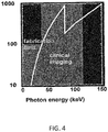
- An embodiment of the current invention is directed to medical applications. Since it is difficult to produce few-micron period gratings with more than ⁇ 100 ⁇ m Au absorber thickness, inclining the gratings at an angle in the 5-25° range makes for 200-1000 ⁇ m effective Au thickness. As is shown in Fig. 4 , this thickness enables >90% X-ray absorption (and thus high interferometer contrast) over the ⁇ 40 keV-110 keV energy range, of interest for medical phase-contrast imaging deep in the body.
- Another embodiment is directed to industrial or non-destructive testing (NDT) applications.
- NDT non-destructive testing
- the effective Au thickness is in the 400-2000 ⁇ m range, which makes for good X-ray absorption and interferometer contrast in the ⁇ 100 keV-250 keV energy range of interest for industrial NDT applications.
- the splitter grating 104 is a reflection grating (not shown in Figure 2A ).
- a reflection grating such as described in Ref. [7], which is incorporated herein by reference, can be used according to some embodiments of the current invention.
- the splitter grating 104 is a transmission grating, as is illustrated schematically in Figure 2A .
- the splitter grating 104 is a transmission grating, similar to analyzer grating 114, such an embodiment of the analyzer grating has a longitudinal dimension, a lateral dimension that is orthogonal to the longitudinal dimension, and a transverse dimension that is orthogonal to the longitudinal and lateral dimensions.
- the splitter grating 104 in this embodiment has a pattern of optically dense regions, each having a longest dimension along the longitudinal dimension and being spaced substantially parallel to each other in the lateral dimension such that there are optically rare regions between adjacent optically dense regions. Each optically dense region has a depth in the transverse dimension that is smaller than a length in the longitudinal dimension.
- the splitter grating 104 is arranged with the longitudinal dimension at a shallow angle ⁇ relative to incident X-rays such that it is less than 30 degrees.
- the splitter grating 104 can be similar in construction as the analyzer grating 114 and arranged similarly at a shallow angle ⁇ as described above with respect to the analyzer grating 114, although placed at a different position along the optical axis.
- FIG. 2B is a schematic illustration of a conventional differential phase contrast X-ray imaging system that can be contrasted with the differential phase contrast X-ray imaging system 100 according to an embodiment of the current invention.
- the gratings are arranged orthogonal to, and in some cases at slightly off-orthogonal angles to the optical axis along which a beam of X-rays travels.
- the longitudinal direction of the source, beam-splitter and analyzer gratings are all in the vertical direction of the illustration.
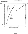
- the thickness of the grating t is the maximum depth of corresponding optically dense regions, such as parallel lines of gold or other high-Z material separated by regions of low-Z material, such as a silicon substrate. According to the conventional approach, one would have to increase the depth of the optically dense regions to operate with higher energy X-rays in order to sufficiently block the higher energy X-rays with the optically dense regions.
- block X-rays is intended to mean that sufficient attenuation is achieved relative to X-rays that pass through the optically rare regions of the grating to permit a useful contrast for the particular application. It is not intended to require absolutely 100% attenuation.
- the splitter grating 104 and the analyzer grating 114 are arranged with a separation determined according to Talbot-Lau conditions according to some embodiments of the current invention.
- the splitter grating 104 and the analyzer grating 114 have grating patterns that are determined according to Talbot-Lau conditions.
- the X-ray illumination system 102 can include an X-ray source 116, and a source grating 118 arranged in an optical path between the X-ray source 116 and the beam splitter 104.
- the source grating 118 provides a plurality of substantially coherent X-ray beams when X-ray source 116 is a spatially extended source of X-rays, as is illustrated schematically in Figure 2A .
- the X-ray illumination system 102 can include combinations of one or more gratings and mirrors, including both transmission and/or reflection gratings.
- Figure 3A is a schematic illustration of an X-ray illumination system 200 according to an embodiment of the current invention.
- the X-ray illumination system 200 can be used as part of the differential phase contrast X-ray imaging system 100 and/or any of the variations described above and/or can be used in conventional systems such as that illustrated in Figure 2B , for example.
- the X-ray illumination system 200 can be used for, or as a portion of, the X-ray illumination system 102.
- the X-ray illumination system 200 is not limited to only these particular applications.
- the X-ray illumination system 200 has a poly-energetic X-ray source 202 and a band-pass filter 204 arranged in an optical path of X-rays 206 from the poly-energetic X-ray source 202.
- the band-pass filter 204 allows X-rays within a band of energies to pass more strongly than X-rays outside the band of energies.
- the band-pass filter 204 includes a high-pass X-ray mirror 208 that reflects a first portion 210 of an incident beam of X-rays 206 that have energies less than a lower pass-band energy and allows a second portion 212 of the incident beam of X-rays to pass therethrough.
- the band-pass filter 204 also includes first beam stop 214 arranged to intercept and at least attenuate the first portion 210 of the incident beam of X-rays 206 that have energies less than the lower pass-band energy, a low-pass X-ray mirror 216 that reflects a portion 218 of the second portion 212 of the incident beam of X-rays 206 after passing through the high-pass X-ray mirror 208 that have energies less than a upper pass-band energy, and a second beam stop 220 arranged to intercept and at least attenuate X-rays that miss the high-pass X-ray mirror 208 prior to reaching the second beam stop 220.
- first beam stop 214 arranged to intercept and at least attenuate the first portion 210 of the incident beam of X-rays 206 that have energies less than the lower pass-band energy
- a low-pass X-ray mirror 216 that reflects a portion 218 of the second portion 212 of the incident beam of X-rays
- the first and second beam stops (214, 220) are arranged to allow a beam of X-rays 222 having energies between the upper pass-band energy and the lower pass-band energy to pass therethrough.
- the band-pass filter 204 is not limited to the particular example illustrated in Figure 3A . In other embodiments, more than three mirrors can be used, for example.
- the X-ray illumination system 200 provides a more monochromatic beam of X-rays than that of the X-ray source 202.
- reflection and/or transmission gratings can be used in combination with the band-pass filter 204 to improve coherence of the X-rays from the poly-energetic X-ray source 202.
- a combination of high-pass mirrors and at least one low-pass mirror can provide combined improved coherence and chromaticity of X-rays from the poly-energetic X-ray source 202.
- the low-pass X-ray mirror can be a membrane X-ray mirror, for example, that has a reflecting layer that is a high-Z material on a support layer that is a low-Z material.
- Z is the atomic number.
- high-Z material is intended to mean materials that include atomic elements with Z at least 42 (for example, but not limited to Rh, Pt, and/or Au) so as to have a relatively strong reflectivity for the X-rays.
- low-Z material is intended to mean materials that include atomic elements with Z less than 14 (for example, but not limited to C, Si, quartz, and/or glass) so as to have a relatively low reflectivity for the X-rays.
- the phase-contrast imaging system of the example illustrated in Figure 2A includes three micro-periodic gratings in a Talbot-Lau interferometer configuration, tilted at equal glancing angles ⁇ , in the range from a few degrees to a few tens of degrees.
- the first grating is a 'source grating', which produces an array of quasi-coherent line sources from an extended incoherent source.
- the second grating is a beam-splitter which produces a high contrast fringe pattern (the 'Talbot pattern') at the analyzer location when illuminated through the source grating.
- an analyzer grating is used to transform changes in the Talbot pattern into intensity changes on a 2-D X-ray detector.
- the system works similarly to the conventional, normal incidence Talbot-Lau interferometer [2,3], sketched for reference in Figure 2B .
- Object When a refractive object is placed in the X-ray beam ("Object" in Figure 2A ) it perturbs the Talbot pattern produced by the beam-splitter.
- the analyzer transforms this perturbation into an intensity change on the detector, which enables imaging and quantifying the X-ray refraction and scatter induced by the object.
- the source and analyzer gratings can be conventional, commercially available absorption gratings made, for example, by filling the gaps in a silicon or photoresist grating with gold, as described in Refs. [5, 6].
- the beam-splitter can be a ⁇ -shift phase grating, also can also be made in the conventional manner.
- the gratings are tilted at a glancing angle and have the absorbing bars along the direction of the incident radiation, as shown schematically in Figure 2A .
- Some embodiments of the current invention can provide a simple, practical and also economical solution to this problem: by tilting the gratings at a glancing angle ⁇ , the effective absorber thickness in the X-ray path increases to t/sin( ⁇ ), with t the physical or normal incidence thickness of the grating. For instance at ⁇ 10° the effective thickness increases by a factor of 6. Thus, a 100 ⁇ m thick, 5 ⁇ m period grating, which is within the present technological capability, appears as a grating of 600 ⁇ m thickness when tilted at a glancing angle of 10° in the direction of the radiation.
- the physical thickness of the beam-splitter is simply that required to produce a ⁇ -phase shift at the desired design energy E 0 , when viewed by X-rays incident at an angle ⁇ ; for instance, if t(0) is the thickness needed for normal incidence operation at E 0 , the thickness required at glancing incidence ⁇ , is t*sin( ⁇ ).
- Some embodiments of the current invention can enable, in this way, building high contrast Talbot-Lau interferometers up to very high X-ray energy.
- Figure 5A plots the computed contrast as a function of energy for an interferometer having 100 ⁇ m thick gratings at normal incidence, and at 10° glancing incidence angle.
- tilting the gratings produces a dramatic contrast increase for energies above 40 keV approximately.
- good contrast obtains in the 40-70 keV range, which is of high interest for medical phase-contrast imaging because in this range the soft tissue dose is at a minimum [1].
- appreciable contrast obtains also above the Au K-edge at 80 keV.
- some embodiments of the current invention can provide high contrast interferometers for even higher X-ray energies.
- the source grating duty-cycle is 37%.
- a broad band of high interferometer contrast obtains in the region ⁇ 90 -130 keV.
- the capability for operation at these high energies makes some embodiments of the current invention also of strong interest for NDT and security applications.
- some embodiments of the current invention can allow one to obtain interferometers with sufficiently large fields of views for medical and other practical applications.
- a commercially available 70x70 mm analyzer grating would enable one to obtain a ⁇ 12x70 mm field of view at 10° incidence and a 9x70 mm field of view at 7° incidence.
- a Moire fringe pattern produced by the tilted gratings is shown in the left panel of Fig. 7A , while a lineout through the pattern is shown in the right panel.
- Fig. 7B illustrates the limited contrast that can be obtained with Talbot-Lau interferometers using normal incidence gratings.
- the Moire pattern in this case has been obtained using 5.4 ⁇ m period gratings, with source and analyzer gratings having nominally 100 ⁇ m thickness, which is about the technological limit for this period.
- the phase grating was a 15 ⁇ m thick Ni grating designed for 40 keV mean energy.
- the incident spectrum was the same as in Fig. 7A .
- the best achievable normal incidence contrast is more than twice lower (V ⁇ 11%) than at glancing incidence.
- the contrast of the glancing incidence interferometer can easily be pushed to even higher values by further tilting the gratings.
- Fig. 7C demonstrates that the glancing angle Talbot-Lau interferometer performs phase-contrast measurements similar to the normal incidence one.
- the left panel in Fig. 7C shows the perturbed Moire pattern obtained with the tilted gratings when imaging a nylon rod of 12 mm diameter.
- the opaque object in the image is a Sn wire of 1.5 mm diameter.
- the nylon rod is almost transparent to X-rays, it nevertheless produces strong Moire fringe shifts near its edges.
- USAXS ultra-small angle scattering
- Another alternative embodiment would be to use energy resolving detectors to select the spectral region of high interferometer contrast.
- this would be for instance the region between 90 keV and 130 keV approximately.
- 2-D pixilated detectors such as CdTe arrays exist nowadays that have high energy resolution, high quantum efficiency and good photon counting capability, at energies up to a few hundred keV.
- This novel approach is of particular interest for situations that can tolerate a higher radiation dose, such as in industrial applications, since a large flux of photons outside the region of high interferometer contrast would not be detrimental.
- the mirror can be a simple, non-patterned mirror that serves only as spectral filter ( Fig. 8A ), or it can be a micro- periodically patterned mirror having strips parallel to the incident X-rays (the 'physical period' geometry described in Ref. 7) that would replace the source grating ( Fig. 8B ). In the latter case the mirror would serve simultaneously as spectral filter and spatial filter, thus reducing the number of optical elements and simplifying the setup. Further, the mirror can be either a total reflection mirror working at angles around 1-1.5 mrad, or a graded multilayer mirror working at larger angles of several mrad.
- This quasi-monochromatic emission can be made very bright using W anode tubes at high voltage (few hundred kV).
- this energy region is ideal for medical phase-contrast imaging deep in the human body.
- Fig. 9 The principle of this embodiment is sketched in Fig. 9 .
- the total reflection on the mirror effectively cuts off the high energy portion of the spectrum, which would contribute to the dose without contributing to the phase contrast image [8].
- the low energy part of the spectrum is cut off by an absorption filter.
- the mirror can be micro-periodically patterned and thus fulfill simultaneously the function of spectral filter and of source grating.
- the field of view of systems combining glancing angle gratings with grazing incidence mirrors such as in Fig. 8 is smaller in the vertical dimension than for pure tilted grating systems.
- a typical value is of several mm by several cm.
- This possibility has been in fact demonstrated experimentally for conventional X-ray imaging in Ref. 10, where tens of laterally graded multilayer mirrors have been stacked one upon the other to make a large area ( ⁇ 10x20 cm) quasi-monochromatic radiographic system.
- the following examples analyze the angular sensitivity needed for refraction enhanced imaging with the Talbot method and proposes ways to optimize the Talbot setup for improved refraction based imaging with conventional X-ray sources. Even though we use examples from medical and high energy density (HED) plasma imaging, the conclusions apply also to other fields, such as material sciences, NDT, or security.
- HED high energy density
- the basic interferometer consists of the beam-splitter (typically a ⁇ -shift; phase grating) followed by an 'analyzer' absorption grating of period g 2 equal to that of the Talbot fringe pattern and placed at the magnified Talbot distance D ⁇ d T /(1-d T /L) from the beam-splitter, where L is the distance between the source and the beam-splitter ( Fig. 10 ).
- the Talbot pattern is shifted, leading to intensity changes behind the analyzer approximately proportional to the angle of refraction of the X-rays.
- g 2 Since hard X-rays are deflected by only a few ⁇ -radians in low-Z matter, g 2 must be of the order of a few ⁇ m and D of the order of the meter to achieve sufficient angular sensitivity.
- Typical angular widths are in the 5-10 ⁇ -radian range and typical contrast values are ⁇ few tens of percent when working with conventional X-ray sources [20,21].
- the decrease comes from the fact that the refraction angle 'seen' by the beam-splitter at a distance R is smaller than that at the object [19].
- Mean energies possible with grating interferometers are up to a few tens of keV, with spectral widths ⁇ E/ ⁇ E> ⁇ 1/m, where m is the Talbot order [13-15, 20-21].
- the upper energy bound is due to technological limits in the fabrication of thick, micron-period absorption gratings [22, 23].
- the optical transmission or throughput of the Talbot interferometer for divergent and polychromatic light is much higher (up to 10-20%) than for crystal ABI systems.
- the Talbot method can thus efficiently utilize the spectrally broad and divergent emission produced by conventional X-ray sources.
- the field of view is limited by the practical grating size at ⁇ 10x10 cm approximately.
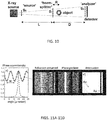
- Figs. 11A-11D The phase-scan technique is illustrated with a numerical simulation in Figs. 11A-11D .
- XWFP code in conjunction with the XOP database [24, 25].
- XWFP computes the X-ray wave propagation, including absorption, refraction and diffraction, through objects such as rods, spheres, and cavities, and through optical elements such as phase and absorption gratings.
- the XOP database allows computing ⁇ and ⁇ for materials of arbitrary composition, by specifying the mass fraction for each element and the mass density of the compound.
- a 100 ⁇ m diameter X-ray opaque Au wire was also included in the simulation to provide a contrast reference.
- the spectrally averaged images were obtained by weighting monochromatic images computed at 0.5 keV intervals with the W tube power spectrum and by including statistical photon noise.
- the maxima of the phase-scan modulations represent the 'bright-field' (BF) intensity and the minima the 'dark-field' (DF) intensity [15].
- Fig. 11B shows the raw, refraction enhanced image obtained at an interferometer position in the middle of the quasi-linear portion of the phase-scan curve, as indicated by the arrow.
- Refraction contrast of ⁇ 20% obtains at edges of the Be rod, showing that the Talbot method can produce contrast enhancements of the order of ⁇ M/ W eff , even without phase-scanning.
- Fig. 11C and 11D show the output of the phase retrieval procedure.
- Fig. 11C shows the phase gradient or 'pure refraction' image, in which the intensity is proportional to the refraction angle, while
- Fig. 11D shows the 'pure attenuation' image [14,15].
- the analysis was done using the Fourier method described in Ref. 15.
- Figs. 11B to 11D illustrate the potential of refraction based imaging: while the weakly absorbing Be object is almost invisible in the attenuation image, it appears with good contrast in the phase gradient and in the refraction enhanced images.
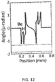
- HED plasma radiography In the typical HED plasma radiography a micron sized X-ray backlighter (usually a laser produced plasma) illuminates a sub-mm, low-Z plasma target of many times the solid density, such as an imploding IFE (Inertial Fusion Energy) capsule. High spatial resolution requires imaging at high magnification (M ⁇ 10-100) [11,26,27].
- Fig. 12 shows the range of refraction angles incident on the beam-splitter for a typical backlighter energy of 22 keV (Ag K- ⁇ , [27]). As seen, while the refraction contrast enables one to discriminate the Be and H layers (otherwise invisible in the attenuation image), the range of refraction angles is small, ⁇ M ⁇ ⁇ 1 ⁇ -radian.
- Soft tissue radiography Soft tissue imaging is one of the most investigated applications of the Talbot method.
- the synchrotron experiments show for instance that X-ray refraction enables imaging of joint soft tissues such as cartilage or tendon, which are important in the diagnostic of arthritis [1,4,18].
- To estimate the typical refraction angles for soft tissues we assumed the case of a small joint and used a simple numerical model or 'phantom' to compute its attenuation and refraction angle profiles.
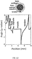
- the phantom consisted of layers of materials simulating bone, cartilage, synovial fluid, connective tissue of the joint capsule, tendon, and skeletal muscle (inset in Fig. 13 ), approximating the anatomy of a human proximal finger joint.
- To compute ⁇ and ⁇ for the joint soft tissues we used the composition and density of body tissues from the compilation by Woodard and White [28].
- refraction angles for the small joint phantom at 25 keV are shown in Fig. 13 .
- the range of refraction angles for cartilage, fluid and joint capsule is very small, ⁇ M in the range of a few tenths of a ⁇ -radian. This is due to the small difference in index of refraction between soft issues (e.g., several % for cartilage and joint fluid).
- These very small refraction angles predicted by our model are also in agreement with the synchrotron experiments; for instance, Shimao et al. estimated refraction angles in the range 0.1-0.4 ⁇ -radian for a human finger joint at 36 keV [18].
- M T (L+D)/L is the Talbot magnification [19,20].
- Fig. 14A shows that once the system length is fixed and the symmetrical setup chosen, the only way to further increase the angular sensitivity is to increase the Talbot order.
- the only way to further increase the angular sensitivity is to increase the Talbot order.
- the interferometer contrast is defined as above.
- the Talbot period was adjusted in each order to match the 2 m interferometer length.
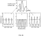
- the contrast curves in Fig. 15 include also the geometrical broadening of the Talbot fringe pattern by the finite source grating openings, simulated by convolving the Talbot pattern at the analyzer with a Gaussian of width s 0 [20,21].
- a practical configuration maximizing the angular sensitivity of the Talbot method is a symmetric setup having gratings of equal period and length of around 2 m.
- the third Talbot order offers a good compromise between angular sensitivity and contrast when using a spectrally broad source.
- Fig. 14A the smallest angular width achievable with a Talbot interferometer in a low order (m ⁇ 3) is still several times larger than that of a crystal system.
- the only way to achieve with the Talbot method angular sensitivity closer to that of crystal optics is to use higher Talbot orders.
- nearly 5 ⁇ -radian angular width can be obtained with a 2 m long interferometer in the 7th order.
- the adjacent peaks are 'harmonics' that produce high contrast Talbot patterns, but having twice the period of the pattern of the central peak. As such, although a broad source spectrum would overlap with these side peaks, they would not contribute to the formation of the refraction image with the full angular sensitivity of the interferometer, but with half this value. In addition, depending on the details of the imaged object, these side peaks could subtract from the effective refraction contrast produced by the central peak, instead of adding to it.
- the solution to simultaneously maximize the angular sensitivity and the effective contrast of Talbot method is thus to work in a high order (m ⁇ 5), while using a quasi-monochromatic X-ray spectrum of width ⁇ E/ ⁇ E> ⁇ 1/m ⁇ 15-20%. Possible ways to do this are described in the following.
- K-line spectra filtered with K-edge absorbers The simplest method to obtain a quasi-monochromatic spectrum is to use a bright K-linc emitter, such as a Mo or Rh anode tube for biomedical applications or an Ag K- ⁇ backlighter for HED plasma radiography, and to filter the emission with a K-edge absorber of the same atomic number as the emitter.
- a bright K-linc emitter such as a Mo or Rh anode tube for biomedical applications or an Ag K- ⁇ backlighter for HED plasma radiography
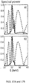
- Figs. 18A-18D The increase in refraction contrast possible using high Talbot orders and K-line/K-edge filtered spectra is illustrated with computed refraction enhanced images of the joint phantom in Figs. 18A-18D .
- the refraction enhanced images are computed for an interferometer phasing at mid-distance between the bright and dark field settings, which as illustrated in Fig. 11B maximizes the refraction contrast.
- Fig. 18A shows as a reference the image obtained assuming the W anode tube spectrum in Fig. 15 and operation in the third Talbot order, optimal for this spectrum.
- the refraction contrast enhancement is too faint to be useful in practice without resorting to phase-scanning and/or CT, which would require multiple exposures.
- Fig. 18B shows that the single exposure contrast can be substantially increased however by using the interferometer in the 7th order and the K-edge filtered Rh spectrum; the cartilage, joint fluid and connective capsule are clearly delineated in this case.
- the relative intensity variation or contrast at the cartilage fluid interface for instance is around 20%.
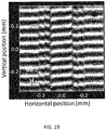
- FIG. 19 shows a Moire fringe image or deflectogram of the IFE capsule modeled in Fig. 12 .
- the use of Moire deflectometry for density profile diagnostic in HED plasmas was demonstrated at the NOVA facility using backlighting with an XUV laser and focusing optics [29].
- the clear Moire fringe shifts at the location of the Be ablator and H fuel layer in Fig. 19 indicate that using the Talbot method with quasi-monochromatic backlighting would provide a simple density profile diagnostic for the capsule, without the need for X-ray lasers or focusing optics.
- X-ray mirrors or reflectors to shape the source spectrum.
- the principle of the method is sketched in Fig. 20 .
- a grazing incidence mirror is placed near the source grating and a slot collimator selects only the reflected beam.
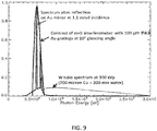
- a first possibility is to use total reflection mirrors. These are simply made of a thin high-Z film (e.g., Au, Ta, Pt) deposited on a low-Z substrate and can reflect with high efficiency (> 60-80%) hard X-rays incident below the critical reflection angle [30]. The sharp energy cutoff due to the total reflection effect can be used to efficiently filter out high energy photons. This is illustrated in Fig. 17B with the computed Rh tube spectrum at 40 kVp, filtered with a 30 ⁇ m Rh absorber followed by reflection on a Pt mirror at 3.5 mrad incidence angle. The mirror was assumed to have 3 ⁇ surface roughness. As can be seen, the parasitic radiation above about 22 keV is completely suppressed, while the radiation in the useful Rh K- ⁇ band is efficiently transmitted.
- a thin high-Z film e.g., Au, Ta, Pt
- mirrors are laterally graded multilayer mirrors as narrow band, high throughput spectral filters. These are synthetic Bragg reflectors for which the period varies along the length, enabling it to reflect a narrow range of wavelengths over the entire length of a planar mirror [31]. Recent experiments demonstrate that at incidence angles of several milli-radians such mirrors can efficiently reflect X-rays up to tens of KeV. For instance, Park et al. demonstrated efficient production ( ⁇ 50% reflectivity) of quasi-monochromatic X-ray bands using a conventional rotating anode X-ray tube and a 100 mm long graded multilayer with period varying between 32 and 38 ⁇ [32].
- Curved HOPG highly ordered pyrolytic graphite reflectors could also be used to produce nearly monochromatic radiation from conventional X-ray sources, as demonstrated with a Mo K- ⁇ mammographic system by Lawaczeck et al. [33].
- the constraint in the mirror filtering method is that the field of view (FOV) height perpendicular to the mirror plane (vertical in Fig. 20 ) is limited to values H ⁇ d at the object location, with ⁇ the difference between the maximum and the minimum incidence angle on the mirror and d the distance between the mirror and the object.
- ⁇ is constrained in turn by the acceptable variation in high energy cutoff across the length of the mirror. For instance, assuming a Rh anode spectrum at 60 kVp and a Pt mirror at 3.5 milli-radian central incidence angle, ⁇ of ⁇ 1 milli-radian would correspond to a cutoff energy variation between 22 keV and 28 keV, which would still allow obtaining high refraction contrast as in Fig.
- the vertical FOV at the object will thus be limited to H ⁇ 1 mm for a 2 m long interferometer having d ⁇ L, as in Fig. 20 .
- the FOV is limited only by the available grating width, since large area X-ray mirrors can nowadays be easily produced.
- the field of view height could be substantially larger, however, since the only limiting factor is the Bragg angle variation along the mirror. For instance, assuming the mirror parameters in Ref. 32, H would increase to ⁇ 2.5 mm for a 2 m long interferometer. Further on, using curved optics the field of view could be even larger; for instance, using a 50 mm long crystal with 480 mm curvature radius placed at 50 mm from the source Lawaczeck et al. achieved a 10 mm high FOV for Mo K- ⁇ radiation, at 550 mm distance from the source [33]. For a 2 m long symmetric Talbot interferometer this would translate into a FOV height of ⁇ 15 mm.
- the mirror filtered Talbot interferometer would need to work in a slot-scan mode, in which either the object or the interferometer field of view is scanned vertically in Fig. 20 . This would require, in principle, longer measurement times than possible with a large field of view, 'cone-beam' system.
- a compensating advantage of the slot-scan geometry could be the strong reduction in large angle scattered radiation reaching the detector. As demonstrated by slot-scan medical systems this reduction substantially improves the overall image contrast [32-34].
- using a quasi-monochromatic spectrum has the advantage of decreasing the radiation dose, since only the wavelength useful for imaging is incident on the object [33,34].
- the slot-scan Talbot systems would also closer resemble the crystal ABI systems, which as above discussed also reject the large angle scattered radiation.
- the measurement time of a mirror filtered slot-scan system could be drastically shortened by using multiple, stacked reflectors. This was demonstrated by Park et al., who used an array of stacked multilayer mirrors to achieve scan times of less than 1 s for an image of ⁇ 200 mm x 240 mm size [32].
- the mirror filtering could enable also extending the range of energy bands available for quasi-monochromatic Talbot interferometry. This could be done using narrow band-pass mirrors in combination with a bright continuum source, such as a rotating W anode tube.
- a first way to obtain narrow energy bands could be to use depth graded multilayer mirrors. These are multilayers for which the period varies with the depth, enabling to efficiently produce energy bands of width ⁇ E/ ⁇ E> ⁇ 10-15%, for X-rays up to several tens of keV energy [35,36].
- a simple and tunable band-pass filter could be made using two total reflection mirrors.
- This dual-mirror filter design is sketched in Fig. 3A and expands on a filtering technique demonstrated at the synchrotrons (the 'transmission mirror') [37,38].
- the first mirror has a high-Z metallic film deposited on a thin (few ⁇ m) low-Z membrane. Total reflection on this mirror rejects the low energy part of the spectrum, while the high energy part is transmitted through the thin membrane with little attenuation.
- the radiation transmitted by the first mirror is then low-pass filtered by a second total reflection mirror.
- FIG. 3B shows an example of the spectral response possible with this design, indicating that band-pass of the order of 15-20% could be achieved for energies of up to several tens of keV. These energy bands would in turn match well the contrast of Talbot interferometers in high orders, as also illustrated in Fig. 3B .
- a further improvement to the mirror filtered interferometer design would be to combine the source grating and the filter mirror in a single optical element, using the micro-periodic mirror concept we described in Ref. 30.
- These are total reflection 'mirror gratings' made by patterning a low-Z substrate with thin ( ⁇ 500 ⁇ ), periodic strips of high-Z metal.
- the difference in reflectivity between the high-Z strips and the low-Z substrate enables one to produce high contrast (up to ⁇ 80%) reflection gratings for X-ray energies up to several tens of keV.
- the use of a micro-periodic mirror instead of the 'source' grating would allow increasing the interferometer contrast at high energy, since the mirror would be the equivalent a very thick absorption grating.
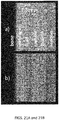
- Figs. 21A-21B This possibility is illustrated in Figs. 21A-21B with calculations of refraction enhanced images for a large joint phantom.
- the phantom has the same layout as the one in Fig. 13 , but with dimensions typical of a knee joint (15 cm muscle diameter, 1.5 mm thick cartilage, fluid and connective tissue layers, 35 mm bone diameter and 6 mm diameter tendon).
- a W anode tube of 0.3 mm spot operated at 70 kVp (typical of knee radiography) and filtered with 0.12 mm Cu and 2 mm Al.
- the detector had 100 ⁇ m pixels.
- Fig. 21A shows the image obtained assuming a 2.2 m long symmetric interferometer of 45 keV mean energy and 5 ⁇ m period, operated in the 5th order, and using 100 ⁇ m thick source and analyzer gratings, with a source grating duty factor of 33%.
- the photons above ⁇ 50 keV are cut by a Pt mirror at 1.8 milli-radian incidence angle.
- the refraction contrast for soft tissues is poor because the absorption contrast between the bars and the openings of the source grating decreases rapidly for X-rays above a few tens of keV.
- Fig. 21B shows the image obtained assuming instead of the source grating a micro-periodic Pt mirror, having 33% duty factor and 80% reflection contrast between the reflecting and non-reflecting strips, independent of energy [30].
- the source grating could be replaced with a micro-periodically patterned multilayer mirror or possibly a patterned HOPG crystal, for near monochromatic differential phase-contrast imaging at high energy.
- Talbot interferometry is a simple technique for refraction based imaging, its angular sensitivity and contrast should be carefully optimized in order to compete with those of the crystal method. This is particularly critical for demanding applications such as soft tissue imaging or high energy density plasma diagnostic, where the refraction angles can be in the sub ⁇ -radian range.
- a practical way to simultaneously maximize the angular sensitivity and contrast of the Talbot method is to use a symmetric interferometer setup with a quasi-monochromatic source spectrum.
- Several solutions are described for shaping the source spectrum, ranging from K-edge absorption filters to reflection on grazing incidence mirrors.
Applications Claiming Priority (3)
| Application Number | Priority Date | Filing Date | Title |
|---|---|---|---|
| US201161513175P | 2011-07-29 | 2011-07-29 | |
| US201261620140P | 2012-04-04 | 2012-04-04 | |
| EP12819196.2A EP2737302B1 (de) | 2011-07-29 | 2012-06-11 | Röntgenbildgebungssystem mit differenzphasenkontrast und komponenten dafür |
Related Parent Applications (2)
| Application Number | Title | Priority Date | Filing Date |
|---|---|---|---|
| EP12819196.2A Division EP2737302B1 (de) | 2011-07-29 | 2012-06-11 | Röntgenbildgebungssystem mit differenzphasenkontrast und komponenten dafür |
| EP12819196.2A Division-Into EP2737302B1 (de) | 2011-07-29 | 2012-06-11 | Röntgenbildgebungssystem mit differenzphasenkontrast und komponenten dafür |
Publications (1)
| Publication Number | Publication Date |
|---|---|
| EP3179240A1 true EP3179240A1 (de) | 2017-06-14 |
Family
ID=47597232
Family Applications (2)
| Application Number | Title | Priority Date | Filing Date |
|---|---|---|---|
| EP12819196.2A Active EP2737302B1 (de) | 2011-07-29 | 2012-06-11 | Röntgenbildgebungssystem mit differenzphasenkontrast und komponenten dafür |
| EP17153899.4A Withdrawn EP3179240A1 (de) | 2011-07-29 | 2012-06-11 | Röntgenbildgebungssystem mit differenzphasenkontrast und komponenten dafür |
Family Applications Before (1)
| Application Number | Title | Priority Date | Filing Date |
|---|---|---|---|
| EP12819196.2A Active EP2737302B1 (de) | 2011-07-29 | 2012-06-11 | Röntgenbildgebungssystem mit differenzphasenkontrast und komponenten dafür |
Country Status (8)
| Country | Link |
|---|---|
| US (3) | US8767915B2 (de) |
| EP (2) | EP2737302B1 (de) |
| JP (2) | JP5624253B2 (de) |
| KR (2) | KR101482699B1 (de) |
| AU (1) | AU2012290646B2 (de) |
| CA (1) | CA2843311C (de) |
| IL (2) | IL230695A (de) |
| WO (1) | WO2013019322A2 (de) |
Cited By (2)
| Publication number | Priority date | Publication date | Assignee | Title |
|---|---|---|---|---|
| CN108469443A (zh) * | 2018-04-18 | 2018-08-31 | 北京航空航天大学 | 基于二维错位吸收光栅的x射线光栅差分相位衬度成像方法及装置 |
| CN111190217A (zh) * | 2020-01-23 | 2020-05-22 | 中国工程物理研究院激光聚变研究中心 | 一种透射带通型辐射流探测器 |
Families Citing this family (61)
| Publication number | Priority date | Publication date | Assignee | Title |
|---|---|---|---|---|
| CN102365687B (zh) | 2009-03-27 | 2015-08-19 | 皇家飞利浦电子股份有限公司 | 消色差的相衬成像 |
| EP2585817B1 (de) * | 2010-06-28 | 2020-01-22 | Paul Scherrer Institut | Verfahren für röntgenstrahlphasenkontrast und dunkelfeldbildgebung mit einer anordnung aus gittern in planarer geometrie |
| EP2761586B1 (de) * | 2011-08-31 | 2022-10-12 | Koninklijke Philips N.V. | Differenzielle phasenkontrastbildgebung mit energieempfindlichem nachweis |
| US20150117599A1 (en) | 2013-10-31 | 2015-04-30 | Sigray, Inc. | X-ray interferometric imaging system |
| KR101378757B1 (ko) * | 2012-08-30 | 2014-03-27 | 한국원자력연구원 | 물질 원소 정보 획득 및 영상 차원의 선택이 가능한 방사선 영상화 장치 |
| US9001967B2 (en) * | 2012-12-28 | 2015-04-07 | Carestream Health, Inc. | Spectral grating-based differential phase contrast system for medical radiographic imaging |
| US9907524B2 (en) | 2012-12-21 | 2018-03-06 | Carestream Health, Inc. | Material decomposition technique using x-ray phase contrast imaging system |
| US9494534B2 (en) | 2012-12-21 | 2016-11-15 | Carestream Health, Inc. | Material differentiation with phase contrast imaging |
| US10096098B2 (en) | 2013-12-30 | 2018-10-09 | Carestream Health, Inc. | Phase retrieval from differential phase contrast imaging |
| US9357975B2 (en) | 2013-12-30 | 2016-06-07 | Carestream Health, Inc. | Large FOV phase contrast imaging based on detuned configuration including acquisition and reconstruction techniques |
| US10578563B2 (en) | 2012-12-21 | 2020-03-03 | Carestream Health, Inc. | Phase contrast imaging computed tomography scanner |
| US9700267B2 (en) | 2012-12-21 | 2017-07-11 | Carestream Health, Inc. | Method and apparatus for fabrication and tuning of grating-based differential phase contrast imaging system |
| US9724063B2 (en) | 2012-12-21 | 2017-08-08 | Carestream Health, Inc. | Surrogate phantom for differential phase contrast imaging |
| US9439613B2 (en) | 2013-02-12 | 2016-09-13 | The Johns Hopkins University | System and method for phase-contrast X-ray imaging |
| CN104095645A (zh) * | 2013-04-03 | 2014-10-15 | 中国科学院高能物理研究所 | 高分辨率和高信噪比的x射线成像系统和成像方法 |
| CN104095646B (zh) * | 2013-04-03 | 2017-03-08 | 中国科学院高能物理研究所 | 高分辨率和高信噪比的双旋ct成像系统和成像方法 |
| US10085701B2 (en) * | 2013-07-30 | 2018-10-02 | Konica Minolta, Inc. | Medical image system and joint cartilage state score determination method |
| WO2015038793A1 (en) * | 2013-09-12 | 2015-03-19 | The United States Of America, As Represented By The Secretary, Department Of Health & Human Services | Demodulation of intensity modulation in x-ray imaging |
| US10297359B2 (en) | 2013-09-19 | 2019-05-21 | Sigray, Inc. | X-ray illumination system with multiple target microstructures |
| US10295485B2 (en) | 2013-12-05 | 2019-05-21 | Sigray, Inc. | X-ray transmission spectrometer system |
| US10269528B2 (en) | 2013-09-19 | 2019-04-23 | Sigray, Inc. | Diverging X-ray sources using linear accumulation |
| US10304580B2 (en) | 2013-10-31 | 2019-05-28 | Sigray, Inc. | Talbot X-ray microscope |
| USRE48612E1 (en) | 2013-10-31 | 2021-06-29 | Sigray, Inc. | X-ray interferometric imaging system |
| CN105745718B (zh) * | 2013-11-05 | 2017-12-19 | 皇家飞利浦有限公司 | 具有对光子通量的快速空间调制的x射线成像设备 |
| CN104622492A (zh) * | 2013-11-11 | 2015-05-20 | 中国科学技术大学 | 一种x射线光栅相位衬度成像装置和方法 |
| WO2015078690A1 (en) | 2013-11-28 | 2015-06-04 | Koninklijke Philips N.V. | Talbot effect based nearfield diffraction for spectral filtering |
| CN105142524A (zh) * | 2014-02-10 | 2015-12-09 | 约翰斯·霍普金斯大学 | 处于高能量的x射线相衬成像和ct的大视场光栅干涉仪 |
| EP2942619A1 (de) * | 2014-05-07 | 2015-11-11 | Paul Scherrer Institut | Beugungsgitteransatz für Röntgengitterinterferometrie im Abtastmodus |
| NZ741924A (en) | 2014-05-08 | 2019-04-26 | L Livermore Nat Security Llc | Methods for 2-color radiography with laser-compton x-ray sources |
| AU2015255872B2 (en) * | 2014-05-08 | 2019-08-15 | Lawrence Livermore National Security, Llc | Ultralow-dose, feedback imaging with laser-compton x-ray and laser-compton gamma-ray sources |
| EP3139836B1 (de) * | 2014-05-09 | 2021-07-07 | The Johns Hopkins University | System und verfahren für phasenkontrast-röntgenbildgebung |
| US10401309B2 (en) | 2014-05-15 | 2019-09-03 | Sigray, Inc. | X-ray techniques using structured illumination |
| US9801600B2 (en) * | 2014-11-17 | 2017-10-31 | Rensselaer Polytechnic Institute | X-ray phase-contrast imaging |
| JP6451400B2 (ja) * | 2015-02-26 | 2019-01-16 | コニカミノルタ株式会社 | 画像処理システム及び画像処理装置 |
| US10352880B2 (en) | 2015-04-29 | 2019-07-16 | Sigray, Inc. | Method and apparatus for x-ray microscopy |
| US10295486B2 (en) | 2015-08-18 | 2019-05-21 | Sigray, Inc. | Detector for X-rays with high spatial and high spectral resolution |
| US10506993B2 (en) | 2015-08-26 | 2019-12-17 | Koninklijke Philips N.V. | Dual energy differential phase contrast imaging |
| JP6632852B2 (ja) * | 2015-10-06 | 2020-01-22 | 浜松ホトニクス株式会社 | X線撮像装置及びx線撮像方法 |
| US10247683B2 (en) | 2016-12-03 | 2019-04-02 | Sigray, Inc. | Material measurement techniques using multiple X-ray micro-beams |
| JP6753342B2 (ja) * | 2017-03-15 | 2020-09-09 | 株式会社島津製作所 | 放射線格子検出器およびx線検査装置 |
| WO2018175570A1 (en) | 2017-03-22 | 2018-09-27 | Sigray, Inc. | Method of performing x-ray spectroscopy and x-ray absorption spectrometer system |
| JP6908106B2 (ja) * | 2017-04-07 | 2021-07-21 | コニカミノルタ株式会社 | 品質検査方法 |
| KR101799346B1 (ko) | 2017-07-12 | 2017-11-20 | 주식회사 우진엔텍 | 펄스 피크시간 포착을 이용한 방사선 검출기의 신호처리장치 |
| JP6844461B2 (ja) * | 2017-07-20 | 2021-03-17 | 株式会社島津製作所 | X線位相イメージング装置および情報取得手法 |
| CN107527670A (zh) * | 2017-08-01 | 2017-12-29 | 中国工程物理研究院激光聚变研究中心 | 一种透过率多级调制的x射线选能器件 |
| EP3494885A1 (de) * | 2017-12-07 | 2019-06-12 | Koninklijke Philips N.V. | Vorrichtung zur präsentation von dunkelfeld-röntgenbildinformationen |
| US10578566B2 (en) | 2018-04-03 | 2020-03-03 | Sigray, Inc. | X-ray emission spectrometer system |
| US10845491B2 (en) | 2018-06-04 | 2020-11-24 | Sigray, Inc. | Energy-resolving x-ray detection system |
| GB2591630B (en) | 2018-07-26 | 2023-05-24 | Sigray Inc | High brightness x-ray reflection source |
| US10656105B2 (en) | 2018-08-06 | 2020-05-19 | Sigray, Inc. | Talbot-lau x-ray source and interferometric system |
| DE112019004433T5 (de) | 2018-09-04 | 2021-05-20 | Sigray, Inc. | System und verfahren für röntgenstrahlfluoreszenz mit filterung |
| CN112823280A (zh) | 2018-09-07 | 2021-05-18 | 斯格瑞公司 | 用于深度可选x射线分析的系统和方法 |
| WO2020252056A1 (en) * | 2019-06-11 | 2020-12-17 | Prc-Desoto International, Inc. | Method and system of inspecting pre-molded sealant parts |
| JP7226171B2 (ja) * | 2019-07-26 | 2023-02-21 | 株式会社島津製作所 | X線位相イメージング装置 |
| WO2021046059A1 (en) | 2019-09-03 | 2021-03-11 | Sigray, Inc. | System and method for computed laminography x-ray fluorescence imaging |
| US11175243B1 (en) | 2020-02-06 | 2021-11-16 | Sigray, Inc. | X-ray dark-field in-line inspection for semiconductor samples |
| JP7395775B2 (ja) | 2020-05-18 | 2023-12-11 | シグレイ、インコーポレイテッド | 結晶解析装置及び複数の検出器素子を使用するx線吸収分光法のためのシステム及び方法 |
| US11348703B2 (en) * | 2020-09-16 | 2022-05-31 | Uchicago Argonne, Llc | Tunable side-bounce x-ray monochromator |
| JP2023542674A (ja) | 2020-09-17 | 2023-10-11 | シグレイ、インコーポレイテッド | X線を用いた深さ分解計測および分析のためのシステムおよび方法 |
| WO2022126071A1 (en) | 2020-12-07 | 2022-06-16 | Sigray, Inc. | High throughput 3d x-ray imaging system using a transmission x-ray source |
| US11885755B2 (en) | 2022-05-02 | 2024-01-30 | Sigray, Inc. | X-ray sequential array wavelength dispersive spectrometer |
Citations (2)
| Publication number | Priority date | Publication date | Assignee | Title |
|---|---|---|---|---|
| US5812629A (en) | 1997-04-30 | 1998-09-22 | Clauser; John F. | Ultrahigh resolution interferometric x-ray imaging |
| US20100091936A1 (en) * | 2008-09-30 | 2010-04-15 | Christian David | X-ray ct system for x-ray phase contrast and/or x-ray dark field imaging |
Family Cites Families (8)
| Publication number | Priority date | Publication date | Assignee | Title |
|---|---|---|---|---|
| US4798446A (en) * | 1987-09-14 | 1989-01-17 | The United States Of America As Represented By The United States Department Of Energy | Aplanatic and quasi-aplanatic diffraction gratings |
| JP3217871B2 (ja) * | 1992-09-24 | 2001-10-15 | 理学電機工業株式会社 | X線分析装置および全反射蛍光x線分析装置 |
| US6137574A (en) * | 1999-03-15 | 2000-10-24 | Zygo Corporation | Systems and methods for characterizing and correcting cyclic errors in distance measuring and dispersion interferometry |
| US6804324B2 (en) * | 2001-03-01 | 2004-10-12 | Osmo, Inc. | X-ray phase contrast imaging using a fabry-perot interferometer concept |
| US7315611B2 (en) * | 2003-06-03 | 2008-01-01 | Monochromatic X-Ray Technologies, Inc. | X-ray reflector exhibiting taper, method of making same, narrow band x-ray filters including same, devices including such filters, multispectral x-ray production via unispectral filter, and multispectral x-ray production via multispectral filter |
| EP1731099A1 (de) | 2005-06-06 | 2006-12-13 | Paul Scherrer Institut | Interferometer zur quantitativen Phasenkontrastbildgebung und -tomographie mit einer inkohärenten polychromatischen Röntgenquelle |
| JP2010253194A (ja) * | 2009-04-28 | 2010-11-11 | Fujifilm Corp | 放射線位相画像撮影装置 |
| DE102011077797A1 (de) * | 2011-06-20 | 2012-12-20 | Siemens Aktiengesellschaft | Patientenlagerungstisch, medizinisches Gerät mit einem Patientenlagerungstisch und Verfahren für einen Patientenlagerungstisch |
-
2012
- 2012-06-11 AU AU2012290646A patent/AU2012290646B2/en not_active Ceased
- 2012-06-11 KR KR1020147005431A patent/KR101482699B1/ko active IP Right Grant
- 2012-06-11 EP EP12819196.2A patent/EP2737302B1/de active Active
- 2012-06-11 US US13/493,392 patent/US8767915B2/en active Active
- 2012-06-11 JP JP2014522824A patent/JP5624253B2/ja active Active
- 2012-06-11 WO PCT/US2012/041908 patent/WO2013019322A2/en active Application Filing
- 2012-06-11 KR KR1020147029323A patent/KR20140129394A/ko not_active Application Discontinuation
- 2012-06-11 CA CA2843311A patent/CA2843311C/en active Active
- 2012-06-11 EP EP17153899.4A patent/EP3179240A1/de not_active Withdrawn
-
2014
- 2014-01-28 IL IL230695A patent/IL230695A/en active IP Right Grant
- 2014-05-16 US US14/280,272 patent/US9557279B2/en active Active
- 2014-09-25 JP JP2014194844A patent/JP5926784B2/ja not_active Expired - Fee Related
-
2015
- 2015-04-16 IL IL238340A patent/IL238340A/en active IP Right Grant
-
2016
- 2016-12-06 US US15/370,280 patent/US9823202B2/en active Active
Patent Citations (2)
| Publication number | Priority date | Publication date | Assignee | Title |
|---|---|---|---|---|
| US5812629A (en) | 1997-04-30 | 1998-09-22 | Clauser; John F. | Ultrahigh resolution interferometric x-ray imaging |
| US20100091936A1 (en) * | 2008-09-30 | 2010-04-15 | Christian David | X-ray ct system for x-ray phase contrast and/or x-ray dark field imaging |
Non-Patent Citations (70)
| Title |
|---|
| A. IIDA ET AL, NUCL. INSTRUM. METH. PHYS. RES., vol. A235, 1985, pages 597 |
| A. RACK ET AL: "Advances in X-Ray/EUV Optics and Components V", PROC. SPIE, vol. 7802, 2010, pages 78020M-1 |
| A. W. STEVENSON ET AL, NUCLEAR INSTRUMENTS AND METHODS IN PHYSICS RESEARCH B, vol. 199, 2003, pages 427 |
| ARFELLI F. ET AL, PHYS. MED. BIOL., vol. 55, 2010, pages 1643 |
| ATSUSHI MOMOSE ET AL: "Phase Tomography by X-ray Talbot Interferometry for Biological Imaging", JAPANESE JOURNAL OF APPLIED PHYSICS, vol. 45, 2006, pages 5254, XP002444795, DOI: doi:10.1143/JJAP.45.5254 |
| BECH M. ET AL, PHYS. MED. BIOL., vol. 54, 2009, pages 2747 |
| BREY E.M. ET AL, TISSUE ENG. PART C METHODS, vol. 16, 2010, pages 1597 |
| C. DAVID; J. ET AL: "Fabrication of diffraction gratings for hard X-ray phase contrast imaging", MICROELECTRONIC ENGINEERING, vol. 84, 2007, pages 1172, XP022061972, DOI: doi:10.1016/j.mee.2007.01.151 |
| CAMILLE K KEMBLE ET AL: "Grazing angle Mach-Zehnder interferometer using reflective phase gratings and a polychromatic, un-collimated light source", OPTICS EXPRESS, vol. 18, no. 26, 20 December 2010 (2010-12-20), pages 27481 - 27492, XP055153060, DOI: 10.1364/OE.18.027481 * |
| CAROL MUEHLEMAN ET AL, J ANAT., vol. 208, 2006, pages 115 - 124 |
| CAROL MUEHLEMAN ET AL: "Multiple-image radiography for human soft tissue", J. ANAT., vol. 208, 2006, pages 115 |
| D CHAPMAN ET AL, PHYS. MED. BIOL., vol. 42, 1997, pages 2015 |
| D. RESS ET AL, REV. SCI. INSTRUM., vol. 66, 1995, pages 579 |
| D. STUTMAN ET AL, APPLIED OPTICS, vol. 49, 2010, pages 4677 |
| D. STUTMAN ET AL, PHYS. MED. BIOL., vol. 56, no. 5697, 2011 |
| D. STUTMAN ET AL, REV. SCI. INSTRUM., vol. 81, 2010, pages 10E504 |
| DAN STUTMAN ET AL: "Development of microperiodic mirrors for hard x-ray phase-contrast imaging", APPLIED OPTICS, OPTICAL SOCIETY OF AMERICA, WASHINGTON, DC; US, vol. 49, no. 25, 1 September 2010 (2010-09-01), pages 4677 - 4686, XP001556464, ISSN: 0003-6935, [retrieved on 20100824], DOI: 10.1364/AO.49.004677 * |
| DAVID C. ET AL, MICROELECTRONIC ENGINEERING, vol. 84, 2007, pages 1172 |
| DONATH T. ET AL, INVESTIGATIVE RADIOLOGY, vol. 45, 2010, pages 445 |
| DONATH T. ET AL, J. APPL. PHYS., vol. 106, 2009, pages 054703 |
| ELENA REZNIKOVA ET AL: "Soft X-ray lithography of high aspect ratio SU8 submicron structures", MICROSYST. TECHNOL., vol. 14, 2008, pages 1683, XP019632828 |
| ENGELHARDT M. ET AL, JOURNAL OF MICROSCOPY, vol. 232, 2008, pages 145 |
| F. PFEIFFER ET AL: "Hard-X-ray dark-field imaging using a grating interferometer", NATURE MATERIALS, vol. 7, 2008, pages 134, XP055003146, DOI: doi:10.1038/nmat2096 |
| H.-S. PARK ET AL., PHYSICS OF PLASMAS, vol. 15, 2008, pages 07270 |
| HAN WEN ET AL, OPTICS EXPRESS, vol. 19, 2011, pages 25093 |
| HEIKKI SUHONEN ET AL: "Refraction and scattering of X-rays in analyzer based imaging", J. SYNCHROTRON RAD., vol. 14, 2007, pages 512 |
| J. LI ET AL: "Phase-sensitive X-ray imaging of synovial joints", OSTEOARTHRITIS AND CARTILAGE, vol. 17, 2009, pages 1193, XP026493264, DOI: doi:10.1016/j.joca.2009.03.005 |
| JEFFREY A. KOCH ET AL, J. APPL. PHYS., vol. 105, 2009, pages 113112 |
| JEFFREY A. KOCH ET AL: "Refraction-enhanced X-ray radiography for inertial confinement fusion and laser-produced plasma applications", J. APPL. PHYS., vol. 105, 2009, pages 113112, XP012125461, DOI: doi:10.1063/1.3133092 |
| K HUSSEIN ET AL, PHYS. MED. BIOL., vol. 54, 2009, pages 1533 |
| K.D.JOENSEN ET AL: "Multilayer and Grazing Incidence X-Ray/EUV Optics II", PROC. SPIE, vol. 2011, 1994, pages 360 |
| KEYRILAINEN J. ET AL, ACTA RADIOLOGICA, vol. 8, 2010, pages 866 |
| M. SANCHEZ DEL RIO ET AL: "XOP: recent developments, in Crystal and Multilayer Optics", PROC. SPIE, vol. 3448, 1998, pages 340 |
| M. SCHUSTER ET AL: "EUV, X-Ray, and Neutron Optics and Sources", PROC. SPIE, vol. 3767, 1999, pages 183 |
| M. STROBL ET AL: "Neutron Dark-Field Tomography", PHYS. REV. LETT., vol. 101, 2008, pages 123902 |
| M. TESTORF ET AL, OPT. COMMUN., vol. 129, 1996, pages 167 - 172 |
| MARTIN BECH ET AL: "Hard X-ray phase-contrast imaging with the Compact Light Source based on inverse Compton X-rays", J. SYNCHROTRON RAD., vol. 16, 2009, pages 43, XP055100380, DOI: doi:10.1107/S090904950803464X |
| MARTIN BECH ET AL: "Soft-tissue phase-contrast tomography with an X-ray tube source", PHYS. MED. BIOL., vol. 54, 2009, pages 2747, XP020149963, DOI: doi:10.1088/0031-9155/54/9/010 |
| MOMOSE A. ET AL, JAPANESE JOURNAL OF APPLIED PHYSICS, vol. 45, 2006, pages 5254 |
| MUEHLEMAN C. ET AL: "Diffraction-enhanced imaging of musculoskeletal tissues using a conventional X-ray tube", ACAD. RADIOL., vol. 16, 2009, pages 918, XP026677450, DOI: doi:10.1016/j.acra.2009.04.006 |
| PAOLA COAN ET AL: "Analyzer-based imaging technique in tomography of cartilage and metal implants: A study at the ESRF", EUROPEAN JOURNAL OF RADIOLOGY, vol. 68, 2008, pages S41 |
| PFEIFFER F. ET AL, NATURE MATERIALS, vol. 7, 2008, pages 134 |
| PFEIFFER F. ET AL, NATURE PHYSICS, vol. 2, 2006, pages 258 |
| PFEIFFER, F. ET AL: "Phase retrieval and differential phase-contrast imaging with low-brilliance X-ray sources", NATURE PHYSICS, vol. 2, 2006, pages 258 |
| R A LEWIS: "Medical phase contrast X-ray imaging: current status and future prospects", PHYS. MED. BIOL., vol. 49, 2004, pages 3573, XP002624599, DOI: doi:10.1088/0031-9155/49/16/005 |
| R. A. LEWIS, PHYS. \LED. BIOL., vol. 49, 2004, pages 3573 |
| R. LAWACZECK ET AL, INVESTIGATIVE RADIOLOGY, vol. 40, 2005, pages 33 |
| R. TOMMASINI, LLNL REPORT, LLNL-TR-429373, 2010 |
| REZNIKOVA E. ET AL, AFICROSYST. TECHNOL, vol. 14, 2008, pages 1683 |
| REZNIKOVA E. ET AL, FICROSYST. TECHNOL., vol. 14, 2008, pages 1683 |
| S. CORNABY ET AL, J. SYNCHROTRON RAD., vol. 15, 2008, pages 371 |
| S. MAYO ET AL, JOURNAL OF PHYSICS: CONFERENCE SERIES, vol. 186, 2009, pages 012105 |
| S.-A. ZHOU ET AL, PHYSIC A MEDICA, vol. 24, 2008, pages 129 |
| S.-A. ZHOU ET AL, PHYSICA MEDICA, vol. 24, 2008, pages 129 |
| SANCHEZ DEL RIO M. ET AL: "Crystal and Multilayer Optics", PROC. SPIE, vol. 3448, 1998, pages 340 |
| SHERIDAN MAYO ET AL: "X-ray phase-contrast micro-tomography and image analysis of wood microstructure", JOURNAL OF PHYSICS: CONFERENCE SERIES, vol. 186, 2009, pages 012105 |
| SHIMAO D. ET AL, EUROPEAN JOURNAL OF RADIOLOGY, vol. 68, 2008, pages S27 |
| SHU-ANG ZHOU ET AL: "Development of phase-contrast X-ray imaging techniques and potential medical applications", PHYSICA MEDICA, vol. 24, 2008, pages 129, XP024341442, DOI: doi:10.1016/j.ejmp.2008.05.006 |
| STUTMAN D ET AL: "Development of optics for x-ray phase-contrast imaging of high energy density plasmas", REVIEW OF SCIENTIFIC INSTRUMENTS, AIP, MELVILLE, NY, US, vol. 81, no. 10, 4 October 2010 (2010-10-04), pages 10E504 - 10E504, XP012145761, ISSN: 0034-6748, DOI: 10.1063/1.3479116 * |
| SUHONEN H. ET AL, J. SYNCHROTRON RAD., vol. 14, 2007, pages 512 |
| TETSUYA YUASA ET AL: "Highly sensitive detection of the soft tissues based on refraction contrast by in-plane diffraction-enhanced imaging CT", NUCLEAR INSTRUMENTS AND METHODS IN PHYSICS RESEARCH, vol. A 591, 2008, pages 546 |
| TILMAN DONATH ET AL., REV. SCI. INSTRUM., vol. 80, 2009, pages 053701 |
| TILMAN DONATH ET AL.: "Phase-contrast imaging and tomography at 60 keV using a conventional X-ray tube source", REV. SCI. INSTRUM., vol. 80, 2009, pages 053701 |
| TIMM WEITKAMP ET AL: "Tomography with grating interferometers at low-brilliance sources", PROC. SPIE 6318, 2006, pages 6318, XP055060370, DOI: doi:10.1117/12.683851 |
| TIMM WEITKAMP: "XWFP: An X-ray wavefront propagation software package for the IDL computer language", PROC. SPIE, vol. 5536, 2004, pages 181 - 189 |
| WEITKAMP T. ET AL: "Developments in X-Ray Tomography V", PROC. SPIE, vol. 6318, 2006, pages 28 |
| WEITKAMP T.: "Advances in Computational Methods for X-Ray and Neutron Optics", PROC. SPIE, vol. 5536, 2004, pages 181 |
| WOODARD H.Q. ET AL, THE BRITISH JOURNAL OF RADIOLOGY, vol. 59, 1986, pages 1209 |
| Y. PARK; S. ET AL, PROC. SPIE 7258 MEDICAL IMAGING 2009: PHYSICS OF MEDICAL IMAGING, 2009, pages 72583L |
| YOGESH S. ET AL: "Laboratory-based X-ray phase-contrast imaging technique for material and medical science applications", APPLIED RADIATION AND ISOTOPES, vol. 66, 2008, pages 1083, XP022700365, DOI: doi:10.1016/j.apradiso.2007.12.008 |
Cited By (2)
| Publication number | Priority date | Publication date | Assignee | Title |
|---|---|---|---|---|
| CN108469443A (zh) * | 2018-04-18 | 2018-08-31 | 北京航空航天大学 | 基于二维错位吸收光栅的x射线光栅差分相位衬度成像方法及装置 |
| CN111190217A (zh) * | 2020-01-23 | 2020-05-22 | 中国工程物理研究院激光聚变研究中心 | 一种透射带通型辐射流探测器 |
Also Published As
| Publication number | Publication date |
|---|---|
| AU2012290646A1 (en) | 2014-03-06 |
| EP2737302A2 (de) | 2014-06-04 |
| WO2013019322A2 (en) | 2013-02-07 |
| US9823202B2 (en) | 2017-11-21 |
| US20140328457A1 (en) | 2014-11-06 |
| JP2015033588A (ja) | 2015-02-19 |
| IL230695A (en) | 2015-05-31 |
| EP2737302A4 (de) | 2015-04-15 |
| US20170146466A1 (en) | 2017-05-25 |
| AU2012290646B2 (en) | 2014-09-04 |
| IL238340A (en) | 2016-03-31 |
| JP5926784B2 (ja) | 2016-05-25 |
| KR20140054153A (ko) | 2014-05-08 |
| US8767915B2 (en) | 2014-07-01 |
| CA2843311C (en) | 2016-06-07 |
| IL230695A0 (en) | 2014-03-31 |
| US20130028378A1 (en) | 2013-01-31 |
| KR101482699B1 (ko) | 2015-01-14 |
| CA2843311A1 (en) | 2013-02-07 |
| JP2014521437A (ja) | 2014-08-28 |
| JP5624253B2 (ja) | 2014-11-12 |
| US9557279B2 (en) | 2017-01-31 |
| IL238340A0 (en) | 2015-06-30 |
| KR20140129394A (ko) | 2014-11-06 |
| EP2737302B1 (de) | 2017-03-22 |
| WO2013019322A3 (en) | 2013-03-28 |
Similar Documents
| Publication | Publication Date | Title |
|---|---|---|
| US9823202B2 (en) | Differential phase contrast X-ray imaging system and components | |
| Stutman et al. | Talbot phase-contrast x-ray imaging for the small joints of the hand | |
| JP4847568B2 (ja) | X線撮像装置およびx線撮像方法 | |
| Stampanoni et al. | Phase-contrast tomography at the nanoscale using hard x rays | |
| US9439613B2 (en) | System and method for phase-contrast X-ray imaging | |
| EP2442722B1 (de) | Korrekturverfahren für differenzielle phasenkontrastbildgebung | |
| US6594335B2 (en) | X-ray phase-contrast medical micro-imaging methods | |
| Coan et al. | Phase-contrast x-ray imaging of the breast: recent developments towards clinics | |
| JP5601909B2 (ja) | X線撮像装置及びこれを用いるx線撮像方法 | |
| US9269469B2 (en) | Arrangement and method for inverse X-ray phase contrast imaging | |
| US20040062349A1 (en) | Phase contrast X-ray device for creating a phase contrast image of an object and method for creating the phase contrast image | |
| Weitkampab et al. | Recent developments in X-ray Talbot interferometry at ESRF-ID19 | |
| AU2014268157A1 (en) | Differential phase contrast X-ray imaging and X-ray Illumination Methods | |
| Kido et al. | Bone cartilage imaging with x-ray interferometry using a practical x-ray tube | |
| Safca et al. | Experimental demonstration of ultrahigh sensitivity Talbot-Lau interferometer for low dose mammography | |
| Safca et al. | PERSPECTIVE ON USING TALBOT-LAU X-RAY PHASE CONTRAST IMAGING FOR ATHEROSCLEROSIS DIAGNOSIS | |
| Kupsch et al. | Progress survey of X-Ray refraction imaging techniques | |
| Stutman et al. | K-edge and mirror filtered x-ray grating interferometers | |
| Pyakurel | Phase and dark field radiography and CT with mesh-based structured illumination and polycapillary optics | |
| Stutman et al. | Towards high-sensitivity and low-dose medical imaging with laser x-ray sources | |
| Makifuchi et al. | Development of X‐Ray Talbot‐Lau Interferometer with a Practical X‐Ray Tube for Medical Imaging | |
| Haibel | Synchrotron Tomography |
Legal Events
| Date | Code | Title | Description |
|---|---|---|---|
| PUAI | Public reference made under article 153(3) epc to a published international application that has entered the european phase |
Free format text: ORIGINAL CODE: 0009012 |
|
| AC | Divisional application: reference to earlier application |
Ref document number: 2737302 Country of ref document: EP Kind code of ref document: P |
|
| AK | Designated contracting states |
Kind code of ref document: A1 Designated state(s): AL AT BE BG CH CY CZ DE DK EE ES FI FR GB GR HR HU IE IS IT LI LT LU LV MC MK MT NL NO PL PT RO RS SE SI SK SM TR |
|
| STAA | Information on the status of an ep patent application or granted ep patent |
Free format text: STATUS: THE APPLICATION IS DEEMED TO BE WITHDRAWN |
|
| 18D | Application deemed to be withdrawn |
Effective date: 20171215 |