EP3177552B1 - Pneumatische fördervorrichtung - Google Patents
Pneumatische fördervorrichtung Download PDFInfo
- Publication number
- EP3177552B1 EP3177552B1 EP15749867.6A EP15749867A EP3177552B1 EP 3177552 B1 EP3177552 B1 EP 3177552B1 EP 15749867 A EP15749867 A EP 15749867A EP 3177552 B1 EP3177552 B1 EP 3177552B1
- Authority
- EP
- European Patent Office
- Prior art keywords
- conveying apparatus
- pneumatic conveying
- plate
- holes
- plates
- Prior art date
- Legal status (The legal status is an assumption and is not a legal conclusion. Google has not performed a legal analysis and makes no representation as to the accuracy of the status listed.)
- Active
Links
Images



Classifications
-
- B—PERFORMING OPERATIONS; TRANSPORTING
- B65—CONVEYING; PACKING; STORING; HANDLING THIN OR FILAMENTARY MATERIAL
- B65G—TRANSPORT OR STORAGE DEVICES, e.g. CONVEYORS FOR LOADING OR TIPPING, SHOP CONVEYOR SYSTEMS OR PNEUMATIC TUBE CONVEYORS
- B65G53/00—Conveying materials in bulk through troughs, pipes or tubes by floating the materials or by flow of gas, liquid or foam
- B65G53/34—Details
- B65G53/40—Feeding or discharging devices
- B65G53/46—Gates or sluices, e.g. rotary wheels
- B65G53/4608—Turnable elements, e.g. rotary wheels with pockets or passages for material
- B65G53/4616—Turnable elements, e.g. rotary wheels with pockets or passages for material with axis of turning parallel to flow
-
- B—PERFORMING OPERATIONS; TRANSPORTING
- B65—CONVEYING; PACKING; STORING; HANDLING THIN OR FILAMENTARY MATERIAL
- B65G—TRANSPORT OR STORAGE DEVICES, e.g. CONVEYORS FOR LOADING OR TIPPING, SHOP CONVEYOR SYSTEMS OR PNEUMATIC TUBE CONVEYORS
- B65G53/00—Conveying materials in bulk through troughs, pipes or tubes by floating the materials or by flow of gas, liquid or foam
- B65G53/34—Details
- B65G53/40—Feeding or discharging devices
- B65G53/46—Gates or sluices, e.g. rotary wheels
-
- F—MECHANICAL ENGINEERING; LIGHTING; HEATING; WEAPONS; BLASTING
- F16—ENGINEERING ELEMENTS AND UNITS; GENERAL MEASURES FOR PRODUCING AND MAINTAINING EFFECTIVE FUNCTIONING OF MACHINES OR INSTALLATIONS; THERMAL INSULATION IN GENERAL
- F16K—VALVES; TAPS; COCKS; ACTUATING-FLOATS; DEVICES FOR VENTING OR AERATING
- F16K3/00—Gate valves or sliding valves, i.e. cut-off apparatus with closing members having a sliding movement along the seat for opening and closing
- F16K3/02—Gate valves or sliding valves, i.e. cut-off apparatus with closing members having a sliding movement along the seat for opening and closing with flat sealing faces; Packings therefor
- F16K3/04—Gate valves or sliding valves, i.e. cut-off apparatus with closing members having a sliding movement along the seat for opening and closing with flat sealing faces; Packings therefor with pivoted closure members
- F16K3/06—Gate valves or sliding valves, i.e. cut-off apparatus with closing members having a sliding movement along the seat for opening and closing with flat sealing faces; Packings therefor with pivoted closure members in the form of closure plates arranged between supply and discharge passages
- F16K3/08—Gate valves or sliding valves, i.e. cut-off apparatus with closing members having a sliding movement along the seat for opening and closing with flat sealing faces; Packings therefor with pivoted closure members in the form of closure plates arranged between supply and discharge passages with circular plates rotatable around their centres
-
- F—MECHANICAL ENGINEERING; LIGHTING; HEATING; WEAPONS; BLASTING
- F16—ENGINEERING ELEMENTS AND UNITS; GENERAL MEASURES FOR PRODUCING AND MAINTAINING EFFECTIVE FUNCTIONING OF MACHINES OR INSTALLATIONS; THERMAL INSULATION IN GENERAL
- F16K—VALVES; TAPS; COCKS; ACTUATING-FLOATS; DEVICES FOR VENTING OR AERATING
- F16K3/00—Gate valves or sliding valves, i.e. cut-off apparatus with closing members having a sliding movement along the seat for opening and closing
- F16K3/02—Gate valves or sliding valves, i.e. cut-off apparatus with closing members having a sliding movement along the seat for opening and closing with flat sealing faces; Packings therefor
- F16K3/04—Gate valves or sliding valves, i.e. cut-off apparatus with closing members having a sliding movement along the seat for opening and closing with flat sealing faces; Packings therefor with pivoted closure members
- F16K3/06—Gate valves or sliding valves, i.e. cut-off apparatus with closing members having a sliding movement along the seat for opening and closing with flat sealing faces; Packings therefor with pivoted closure members in the form of closure plates arranged between supply and discharge passages
- F16K3/08—Gate valves or sliding valves, i.e. cut-off apparatus with closing members having a sliding movement along the seat for opening and closing with flat sealing faces; Packings therefor with pivoted closure members in the form of closure plates arranged between supply and discharge passages with circular plates rotatable around their centres
- F16K3/085—Gate valves or sliding valves, i.e. cut-off apparatus with closing members having a sliding movement along the seat for opening and closing with flat sealing faces; Packings therefor with pivoted closure members in the form of closure plates arranged between supply and discharge passages with circular plates rotatable around their centres the axis of supply passage and the axis of discharge passage being coaxial and parallel to the axis of rotation of the plates
-
- B—PERFORMING OPERATIONS; TRANSPORTING
- B65—CONVEYING; PACKING; STORING; HANDLING THIN OR FILAMENTARY MATERIAL
- B65G—TRANSPORT OR STORAGE DEVICES, e.g. CONVEYORS FOR LOADING OR TIPPING, SHOP CONVEYOR SYSTEMS OR PNEUMATIC TUBE CONVEYORS
- B65G2812/00—Indexing codes relating to the kind or type of conveyors
- B65G2812/16—Pneumatic conveyors
- B65G2812/1608—Pneumatic conveyors for bulk material
- B65G2812/1616—Common means for pneumatic conveyors
- B65G2812/1625—Feeding or discharging means
Definitions
- the present invention relates to a pneumatic conveying apparatus. More particularly, the present invention relates to an adjustable multi-hole orifice plate which can be used in a pneumatic conveying apparatus to assist in the discharge of material.
- Orifice plates are used to control the flow of gas through the gas distribution manifold.
- the number and size of holes required in the orifice plate can be calculated using real life data and using the following mathematical calculation: the gas flow (volume / time); the area of the orifice (area) and the velocity of the gas (distance/time).
- a pneumatic conveying apparatus comprising:
- the present invention therefore resides in the provision of an adjustable multi-hole orifice plate which can be used in a pneumatic conveying apparatus to assist in the discharge of material.
- the adjustable multi-hole orifice plate may be mounted in pipework with a flow of gas moving through the hoes in the multi-hole orifice plate.
- the holes may have a size of about 1 - 20 mm or preferably about 2 - 8 mm.
- the adjustable multi-hole orifice plate may therefore comprise two circular plates: a front (i.e. top) plate and a back (i.e. bottom) plate.
- the radial slots extend partially around the circumference of the front plate.
- the back plate may comprise holes located at the same radius as the apertures or slots in the front plate and these can therefore be exposed (i.e. opened) or closed by rotating the front and/or back plates.
- the rotation of the front and back plates may be adjusted using simple hand tools such as a spanner to undo a locking nut.
- the required number of holes may be exposed by rotating the front plate with radial slots over the bottom plate with radially drilled holes. Once the desired number of holes are uncovered the two plates may be locked in position by tightening the screw and nut that are located on the axis of the plates.
- the adjustable multi-hole orifice may be used as part of conveying apparatus for dry solids. Often such solids contaminate other kinds of adjustable flow control reducing their performance.
- the present invention resides in the provision of an adjustable multi-hole orifice plate which can be used in a pneumatic conveying apparatus to assist in the discharge of material.
- Figure 1 is a representation of an adjustable multi-hole orifice 10 mounted in pipework 12. There is also shown a locking screw and nut 14. There is shown a gas flow moving from the left to the right through the multi-hole orifice 10.
- the adjustable multi-hole orifice 10 is, for example, made from any of the following suitable materials: stainless steel; plastics; ABS and nylon.
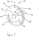
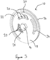
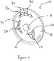
- FIGS 2 to 4 show the operation of the adjustable multi-hole orifice 10.
- the adjustable multi-hole orifice 10 comprises two circular plates: a front (i.e. top) plate 18 and a back (i.e. bottom) plate 16.
- the front plate 18 has a series of radial slots: a large slot 22 extending around toward the outer periphery of the front plate 18; and three smaller slots 24, 26, 28 closer to the centre of the front plate 18.
- the back plate 16 has holes located at the same radius as the slots 24, 26, 28 and these can therefore be exposed (i.e. opened) or closed by rotating the front and back plates 16, 18.
- the rotation of the front and back plates 16, 18 can be adjusted using simple hand tools. Therefore, as opposed to prior art devices no drilling or welding is required. Moreover, the rotation of the front and back plates 16, 18 can be altered adjacent to the conveying vessel meaning that the alteration can be done very simply and quickly.
- the front and back plates 16, 18 are mounted on a common axis with the locking screw and nut 14 holding them in place.
- the required number of holes 20 is achieved by rotating the front plate 18, with radial slots 22, 24, 26, 28 over the bottom plate 16 with radially drilled holes 20. Once the desired number of holes 20 are uncovered the two plates 16, 18 can be locked in position by tightening the screw and nut 14 that are located on the axis of the plates 16, 18. The maximum number and size of holes 20 are dependent on the size of the plates 16, 18.
- the adjustable multi-hole orifice 10 would be used as part of conveying apparatus for dry solids. Often such solids contaminate other kinds of adjustable flow control reducing their performance.
- Figure 2 shows the adjustable multi-hole orifice 10 in the minimum hole position where only one hole 20 is present.
- the stop pin 30 is shown abutting against the end of the slot 22 and preventing further movement to one side.
- the front plate 18 has been rotated to expose eight holes 20.
- the front plate 18 has been further rotated to expose twelve holes 20 and is in the maximum hole position. In the configuration shown in Figure 4 the maximum amount of flow will be allowed through the orifice 10.
- FIG. 5 is a representation of a dispensing vessel 100 according to the present invention.
- the dispensing vessel 100 comprises an inlet dome valve 110, a vessel shell 112, a pressure regulator 114, a main blow valve 116 and an outlet blend 118.
- the multi-hole orifice plates 120, 122, 124 are similar to those shown in Figures 2 to 4 . Therefore, the multi-hole orifice plates 120, 122, 124 can be adjusted as previously described by rotating a front and/or back plate to expose or cover a series of holes which allow the flow of material through the dispensing vessel 100 to be controlled.
- FIG. 6 is a representation of a twin vessel pneumatic injection apparatus 200 according to a further embodiment of the present invention. There is shown a dispensing vessel 210 and a lock vessel 212. This embodiment of the invention has two multi-hole orifice plates 214, 216. The multi-hole orifice plates 214, 216 are as previously described and operate in a similar manner.
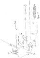
- Figure 7 is a representation of pneumatic conveying apparatus 300 known in the field as a densphase pneumatic conveying apparatus which can be used on any of the following:
- the pneumatic conveying apparatus 300 comprises a dispense vessel 310 and a lock vessel 312.
- This embodiment of the invention has three multi-hole orifice plates 314, 316, 318.
- the multi-hole orifice plates 314, 316, 318 are as previously described and operate in a similar manner.
- any suitable type and shape of front and back plate may be used.
- the device may also comprise any suitable number and arrangement of holes which can be opened and closed by rotating the front and/or back plate.
Landscapes
- Engineering & Computer Science (AREA)
- Mechanical Engineering (AREA)
- General Engineering & Computer Science (AREA)
- Furnace Charging Or Discharging (AREA)
- Air Transport Of Granular Materials (AREA)
- Filling Or Emptying Of Bunkers, Hoppers, And Tanks (AREA)
Claims (12)
- Pneumatische Fördereinrichtung (100, 200, 300), umfassend:eine einstellbare Mehrloch-Messblende (10), die eine vordere und hintere Scheibe (18, 16) aufweist, wobei die vordere und hintere Scheibe (18, 16) auf einer gemeinsamen Achse mit einer Feststellschraube und Mutter (14), die sie in Position halten, montiert sind;wobei die vordere Scheibe (18) eine Reihe radialer Öffnungen oder Schlitze (24, 26, 28) aufweist und die hintere Scheibe eine Reihe Löcher (20) aufweist;wobei die vordere Scheibe (18) eine Reihe radialer Schlitze (24, 26, 28), die sich um die vordere Scheibe herum erstrecken, einen Schlitz (22), der sich um den Außenumfang der vorderen Scheibe und der hinteren Scheibe (16) erstreckt, umfasst und einen Anschlagstift (30) in dem Schlitz (22) aufweist, wobei, wenn der Anschlagstift gegen ein Ende des Schlitzes (22), der sich um den Außenumfang der vorderen Scheibe erstreckt, stößt, ein weitere Bewegung verhindert wird; undwobei die Messblende eingestellt werden kann, indem die vordere und/oder hintere Scheibe so gedreht werden, dass die erforderliche Anzahl Löcher geschlossen und freigelegt werden und dadurch der Luftstrom durch einen Verteiler und infolgedessen der Materialaustrag gesteuert wird.
- Pneumatische Fördereinrichtung (100, 200, 300) nach Anspruch 1, wobei die einstellbare Mehrloch-Messblende (10) in einer Rohrleitung (12) mit einem Gasstrom, der sich durch die Löcher (20) der Mehrloch-Messblende bewegt, montiert ist.
- Pneumatische Fördereinrichtung (100, 200, 300) nach Anspruch 1 oder 2, wobei die einstellbare Mehrloch-Messblende (10) zwei kreisförmige Scheiben umfasst.
- Pneumatische Fördereinrichtung (100, 200, 300) nach einem der vorhergehenden Ansprüche, wobei die hintere Scheibe (16) Löcher (20) umfasst, die sich im gleichen Radius wie die Schlitze (24, 26, 28) in der vorderen Scheibe befinden.
- Pneumatische Fördereinrichtung (100) nach einem der vorhergehenden Ansprüche, wobei die pneumatische Fördereinrichtung einen Einlassdom (110), einen Behältermantel (112), einen Druckregler (114), ein Hauptabblaseventil (116) und einen Auslassverbund (118) umfasst.
- Pneumatische Fördereinrichtung (200) nach einem der vorhergehenden Ansprüche, wobei die pneumatische Fördereinrichtung eine pneumatische Doppelbehälter-Einspritzeinrichtung ist, die einen Abgabebehälter (210) und einen Schleusbehälter (212) umfasst.
- Pneumatische Fördereinrichtung (100, 200, 300) nach einem der vorhergehenden Ansprüche, wobei die pneumatische Fördereinrichtung mehrere einstellbare Mehrloch-Messblenden (120, 122, 124, 214, 216, 314, 316, 318) umfasst.
- Pneumatische Fördereinrichtung (100, 200, 300) nach einem der vorhergehenden Ansprüche, wobei die pneumatische Fördereinrichtung 1 - 10 einstellbare Mehrloch-Messblenden umfasst.
- Pneumatische Fördereinrichtung (100, 200, 300) nach einem der vorhergehenden Ansprüche, wobei die pneumatische Fördereinrichtung 2 oder 3 einstellbare Mehrloch-Messblenden umfasst.
- Verfahren zum Verwenden einer pneumatischen Fördereinrichtung (100, 200, 300) nach einem der vorhergehenden Ansprüche, wobei während der Verwendung die erforderliche Anzahl Löcher (20) freigelegt werden, indem die vordere Scheibe (18) mit radialen Schlitzen (24, 26, 28) über der unteren Scheibe (16) mit radial gebohrten Löchern (20) gedreht wird, und wobei, sobald die gewünschte Anzahl Löcher freigelegt sind, die zwei Scheiben in Position festgestellt werden, indem die Schraube und Mutter (14) festgezogen werden, die sich auf der Achse der Scheiben befinden.
- Verfahren zum Verwenden einer pneumatischen Fördereinrichtung (100, 200, 300) nach einem der Ansprüche 1 bis 9, wobei die einstellbare Mehrloch-Messblende (10) als Teil einer Fördereinrichtung für trockene Feststoffe verwendet wird.
- Verfahren zum Verwenden einer pneumatischen Fördereinrichtung (100, 200, 300) nach einem der Ansprüche 1 bis 9, wobei die pneumatischen Fördereinrichtung in einer der folgenden verwendet wird:• Gypsindustrie für das Überführen von vorkalzinierten Materialien, Zusätzen, Putz und die Wiederverwertung von Abfallmaterial• Eisen- und Stahlindustrie für das Überführen von Sinterfeinerz, Staubförderung, stückiger, körniger und pulverisierter Kohle und Ofenschlacke• Nicht-Eisenindustrien für das Überführen von Rücklaufschrott, metallurgischen Stäuben, Kalk, gekörntem Draht, Zink, stückiger, körniger und pulverisierter Kohle und Stäuben• Aluminiumindustrie für das Überführen von frischem Aluminiumoxid, Fluorit, Flugstäuben, Spänen, Verdichten von stückiger Kohle, Staub aus bearbeiteter Kohle und wiederverwerteten Materialien.
Applications Claiming Priority (2)
| Application Number | Priority Date | Filing Date | Title |
|---|---|---|---|
| GB1413984.4A GB2528954B (en) | 2014-08-07 | 2014-08-07 | Adjustable multi-hole orifice plate in a pneumatic conveying apparatus |
| PCT/GB2015/052294 WO2016020700A1 (en) | 2014-08-07 | 2015-08-07 | Adjustable multi-hole orifice plate in a pneumatic conveying apparatus |
Publications (2)
| Publication Number | Publication Date |
|---|---|
| EP3177552A1 EP3177552A1 (de) | 2017-06-14 |
| EP3177552B1 true EP3177552B1 (de) | 2019-12-18 |
Family
ID=51629429
Family Applications (1)
| Application Number | Title | Priority Date | Filing Date |
|---|---|---|---|
| EP15749867.6A Active EP3177552B1 (de) | 2014-08-07 | 2015-08-07 | Pneumatische fördervorrichtung |
Country Status (7)
| Country | Link |
|---|---|
| US (1) | US10000347B2 (de) |
| EP (1) | EP3177552B1 (de) |
| KR (1) | KR102337500B1 (de) |
| CN (1) | CN106660716B (de) |
| DK (1) | DK3177552T3 (de) |
| GB (1) | GB2528954B (de) |
| WO (1) | WO2016020700A1 (de) |
Families Citing this family (12)
| Publication number | Priority date | Publication date | Assignee | Title |
|---|---|---|---|---|
| CN105840852A (zh) * | 2016-04-27 | 2016-08-10 | 池州大自然环保工程有限公司 | 快速开关排泥排灰阀 |
| GB2577436B (en) * | 2017-06-20 | 2024-11-27 | Control Components | Multi-stage, multi-path rotary disc valve |
| DE102018204903B4 (de) * | 2018-03-29 | 2020-10-08 | Vitesco Technologies GmbH | Vorrichtung zur Nachbehandlung von Abgasen |
| CN115717561A (zh) * | 2018-09-28 | 2023-02-28 | 康明斯排放处理公司 | 用于动态控制过滤效率和燃料经济性的系统和方法 |
| CN109364595A (zh) * | 2018-11-27 | 2019-02-22 | 黄冬艳 | 一种节能环保废气处理装置 |
| JP7544718B2 (ja) * | 2019-01-18 | 2024-09-03 | トライコヤ テクノロジーズ エルティーディー | 第1のガス圧の第1の環境から第2のガス圧の第2の環境へ固体粒子を移送するシステム及び方法 |
| CN110018291B (zh) * | 2019-04-18 | 2020-05-05 | 中国矿业大学 | 一种充填开采流固耦合物理相似模拟实验测试系统 |
| AT522142B1 (de) * | 2019-04-26 | 2020-08-15 | Nowe Gmbh | Vorrichtung zum Befüllen eines Behälters mit Schüttgut, insbesondere Sand |
| IT201900009456A1 (it) * | 2019-06-19 | 2020-12-19 | Salce S R L | Unita’ dosatrice con capacita’ di dosare in modo controllato una sostanza in forma polverosa, e corrispondente macchina per laboratorio di tintoria includente tale unita’ dosatrice |
| JP7365575B2 (ja) * | 2019-08-09 | 2023-10-20 | 三菱マテリアル株式会社 | 鉱石連続供給装置 |
| US12510077B2 (en) | 2021-07-08 | 2025-12-30 | Industrial Vacuum Transfer Services Usa, Llc | Air compressor having vacuum and associated methods for loading and extracting materials |
| US12485459B2 (en) * | 2021-07-08 | 2025-12-02 | Industrial Vacuum Transfer Services Usa, Llc | Systems, assemblies, and methods for pyrophoric material extraction |
Citations (2)
| Publication number | Priority date | Publication date | Assignee | Title |
|---|---|---|---|---|
| US5370369A (en) * | 1992-06-01 | 1994-12-06 | Outokumpu Research Oy | Multipurpose burner designed for adjusting the supply of a reaction gas to be fed into a smelting furnace |
| US20040082251A1 (en) * | 2002-10-29 | 2004-04-29 | Applied Materials, Inc. | Apparatus for adjustable gas distribution for semiconductor substrate processing |
Family Cites Families (45)
| Publication number | Priority date | Publication date | Assignee | Title |
|---|---|---|---|---|
| AT122567B (de) * | 1929-10-04 | 1931-04-25 | Ganz & Comp Danubius Maschinen | Steuervorrichtung für pneumatisch geschaltete Geschwindigkeitswechselgetriebe, insbesondere von Motorfahrzeugen. |
| US2550781A (en) * | 1946-12-09 | 1951-05-01 | Richard R Colburn | Concrete aggregate feeder having a measuring rotor and an adjustable feed hopper |
| US3178235A (en) * | 1963-03-29 | 1965-04-13 | Koppers Co Inc | Rotary feeder |
| US3776599A (en) * | 1966-01-03 | 1973-12-04 | Cons Eng Co | Self-purging, pneumatic conveying apparatus including fluid flow pumps on scales, with agitator, vacuum filled, with material dryer, and of varied means of sequential value operation |
| DE1950253A1 (de) * | 1969-10-06 | 1971-04-22 | Friedrichs Ingo Dipl Ing | Hydrostatisch entlastete Steuerung mit geringem Durchflusswiderstand |
| AT304224B (de) * | 1970-07-10 | 1972-12-27 | Deckel Ag Friedrich | Hydraulisches Steuerventil für Nachformfräsmaschinen |
| GB1386247A (en) * | 1971-08-05 | 1975-03-05 | Vertue C R F | Device for delivering particulate material |
| DE2413420A1 (de) * | 1974-03-20 | 1975-10-02 | Klaus Dipl Ing Scheuermann | Mischbatteriesystem |
| US4009912A (en) * | 1974-11-04 | 1977-03-01 | Joseph Mraz | Pneumatic conveying apparatus and method |
| GB1488581A (en) * | 1975-01-08 | 1977-10-12 | Newport Forge & Eng Ltd | Pneumatically operated conveyor systems for pulverulent or particulate materials |
| GB1534118A (en) * | 1977-07-21 | 1978-11-29 | Enfo Grundlagen Forschungs Ag | Closing member for a ring valve |
| US4182383A (en) * | 1978-06-23 | 1980-01-08 | General Electric Company | Fluidized bed powder discharge and metering method and apparatus |
| DE3204937C2 (de) * | 1982-02-12 | 1983-12-22 | J.M. Voith Gmbh, 7920 Heidenheim | Drosselblende zum Einbau in die Spaltwasserleitung von Turbinen sowie Pumpen |
| US4511291A (en) * | 1982-06-03 | 1985-04-16 | Quates Sr Norman C | Vacuum material conveying apparatus |
| DE3239925A1 (de) * | 1982-10-28 | 1984-05-03 | Friedrich Grohe Armaturenfabrik Gmbh & Co, 5870 Hemer | Absperr- und regulierventil |
| US4765781A (en) * | 1985-03-08 | 1988-08-23 | Southwestern Public Service Company | Coal slurry system |
| SE457348B (sv) * | 1985-05-09 | 1988-12-19 | Abb Stal Ab | Pneumatiskt transportsystem med materialmatare |
| US4662799A (en) * | 1985-05-17 | 1987-05-05 | Fuller Company | Apparatus and process for pneumatically conveying particulate material |
| BR8602938A (pt) | 1985-06-28 | 1987-02-17 | Union Carbide Corp | Dispositivo de dosagem |
| US5222840A (en) * | 1991-06-21 | 1993-06-29 | The Stolle Corporation | Double plenum air conveyor/accumulator |
| GB9114729D0 (en) * | 1991-07-09 | 1991-08-28 | Cmb Foodcan Plc | Valve |
| US5407305A (en) * | 1993-04-29 | 1995-04-18 | Semco, Inc. | Continuous dense phase conveying method utilizing high pressure gas at predetermined gas pressures within a conveying pipe |
| US5676173A (en) * | 1994-11-04 | 1997-10-14 | T I Properties, Inc. | In-line venturi |
| US5997220A (en) * | 1994-12-14 | 1999-12-07 | Wormser Systems, Inc. | Vertical-shaft airlock |
| JPH102435A (ja) * | 1996-06-18 | 1998-01-06 | Yunibaasu:Kk | エアーマット用のロータリー弁 |
| DE19815775A1 (de) * | 1998-04-08 | 1999-10-14 | Bosch Gmbh Robert | Drallscheibe und Brennstoffeinspritzventil mit Drallscheibe |
| AUPP789898A0 (en) * | 1998-12-23 | 1999-01-21 | Birrus Engineering Pty Ltd | Conveying |
| CN2440028Y (zh) * | 2000-09-26 | 2001-07-25 | 杭州华源人工环境工程有限公司 | 多仓式密相输送泵 |
| US6722210B2 (en) * | 2001-08-31 | 2004-04-20 | Texas Instruments Incorporated | System and method for measuring air flow at multiple points of an air channel |
| US7156372B2 (en) * | 2003-12-19 | 2007-01-02 | Eastman Kodak Company | Non-contact valve for particulate material |
| US7007914B2 (en) * | 2004-05-14 | 2006-03-07 | United States Gypsum Company | Slurry mixer constrictor valve |
| DE102004040221B4 (de) * | 2004-08-19 | 2009-01-08 | Pierburg Gmbh | Regelbare Zwei-Wege-Ventilvorrichtung für eine Verbrennungskraftmaschine |
| CN100472108C (zh) * | 2006-01-05 | 2009-03-25 | 崔荀 | 一种陶瓷阀片组件及装有该组件的冷热水混合阀 |
| DE102007009758B4 (de) * | 2007-02-27 | 2024-11-28 | Metso Outotec Finland Oy | Verfahren und Vorrichtung zur Regelung eines Feststoffstromes |
| US8061295B2 (en) * | 2007-10-25 | 2011-11-22 | Aexcel Corporation | Bead applicator |
| US20090124945A1 (en) * | 2007-11-08 | 2009-05-14 | Reich Bonnie E | High Efficiency Water Pick Cleaning Apparatus and Showerhead |
| US20100034049A1 (en) * | 2008-08-06 | 2010-02-11 | Nicholas William Ferri | Adjustable Diffusing Coal Valve |
| US8337122B2 (en) * | 2009-11-09 | 2012-12-25 | Magnum Systems, Inc. | Continuous semi-dense pneumatic conveying system and method |
| US8893703B2 (en) * | 2009-11-16 | 2014-11-25 | Colorado State University Research Foundation | Combustion chamber for charcoal stove |
| US8377387B2 (en) * | 2010-06-23 | 2013-02-19 | General Electric Company | Fluidization device for solid fuel particles |
| JP6200419B2 (ja) * | 2011-06-03 | 2017-09-20 | ラディセンス ダイアグノスティクス リミテッド | ビーズベースの免疫アッセイで使用するための微小流体ディスク |
| CA2892024C (en) * | 2012-12-05 | 2021-01-19 | Yoshino Gypsum Co., Ltd. | Mixing and stirring device, mixing and stirring method, and method for manufacturing lightweight gypsum board |
| CN203477388U (zh) * | 2013-04-25 | 2014-03-12 | 中国核电工程有限公司 | 流量可调节式限流孔板 |
| JP6152759B2 (ja) * | 2013-09-17 | 2017-06-28 | 株式会社ジェイテクト | オイルポンプ |
| CN203670848U (zh) * | 2014-01-15 | 2014-06-25 | 浙江欧意阀门有限公司 | 流量调节阀的密封阀板 |
-
2014
- 2014-08-07 GB GB1413984.4A patent/GB2528954B/en active Active
-
2015
- 2015-08-07 EP EP15749867.6A patent/EP3177552B1/de active Active
- 2015-08-07 KR KR1020177004918A patent/KR102337500B1/ko active Active
- 2015-08-07 DK DK15749867.6T patent/DK3177552T3/da active
- 2015-08-07 US US15/502,065 patent/US10000347B2/en active Active
- 2015-08-07 CN CN201580042367.2A patent/CN106660716B/zh active Active
- 2015-08-07 WO PCT/GB2015/052294 patent/WO2016020700A1/en not_active Ceased
Patent Citations (2)
| Publication number | Priority date | Publication date | Assignee | Title |
|---|---|---|---|---|
| US5370369A (en) * | 1992-06-01 | 1994-12-06 | Outokumpu Research Oy | Multipurpose burner designed for adjusting the supply of a reaction gas to be fed into a smelting furnace |
| US20040082251A1 (en) * | 2002-10-29 | 2004-04-29 | Applied Materials, Inc. | Apparatus for adjustable gas distribution for semiconductor substrate processing |
Also Published As
| Publication number | Publication date |
|---|---|
| EP3177552A1 (de) | 2017-06-14 |
| GB201413984D0 (en) | 2014-09-24 |
| US10000347B2 (en) | 2018-06-19 |
| KR102337500B1 (ko) | 2021-12-10 |
| GB2528954B (en) | 2017-05-24 |
| US20170225909A1 (en) | 2017-08-10 |
| GB2528954A (en) | 2016-02-10 |
| CN106660716B (zh) | 2021-01-26 |
| KR20170039208A (ko) | 2017-04-10 |
| WO2016020700A1 (en) | 2016-02-11 |
| DK3177552T3 (da) | 2020-03-16 |
| CN106660716A (zh) | 2017-05-10 |
Similar Documents
| Publication | Publication Date | Title |
|---|---|---|
| US10000347B2 (en) | Adjustable multi-hole orifice in a pneumatic conveying apparatus | |
| US4759507A (en) | Size reduction machine having an external gap adjustment | |
| US10556239B2 (en) | Method for operating an installation comprising at least one assembly with a rotating surface | |
| US4090956A (en) | Hydrocyclone | |
| EP1419823B1 (de) | Spiralstrahlmühle | |
| EP3160629B1 (de) | Anordnung zur steuerung des abflusses aus unter druck stehenden verarbeitungsbehältern und biomassenbehandlungssystem | |
| EP3645152B1 (de) | Gebläseeinheit für pneumatische mischer und vorrichtung zur pneumatischen mischung von körnchen, pulvern und/oder flüssigkeiten mit dieser gebläseeinheit | |
| CN113767054B (zh) | 圆顶阀可调节顶板 | |
| CN101923010B (zh) | 核级不锈钢锻件的局部曲面圆弧取样方法 | |
| DE69402546T2 (de) | Pneumatisches fördersystem | |
| CN216763577U (zh) | 一种向两台成球机输送耐火球的送料装置 | |
| US3010610A (en) | Solids flow control device and method | |
| US20110085883A1 (en) | Adjustable wear and diversion device for bulk material transfer systems and method of using the same | |
| CN113522464A (zh) | 一种溢流型球磨机排矿装置 | |
| CN204173613U (zh) | 一种圆盘给料机给料闸门 | |
| CN206623043U (zh) | 可变间距反应釜法兰紧固工具 | |
| CN201889103U (zh) | 一种轴盘式排矿装置 | |
| CN207056822U (zh) | 一种粉料用分级器 | |
| CN111632741A (zh) | 耐磨型蜗壳进料机座 | |
| KR102910625B1 (ko) | 분체 유량 분배기 및 이를 이용한 분체 유량 분배 방법 | |
| CN110577028B (zh) | 一种溜槽翻板防卡阻装置 | |
| JP6116736B1 (ja) | 流量調節弁 | |
| CN102462982A (zh) | 轴盘式排矿装置 | |
| CN212237114U (zh) | 一种混合机刀臂安装座保护装置和采用该装置的混合机 | |
| CN208616724U (zh) | 一种改进的螺旋输送机 |
Legal Events
| Date | Code | Title | Description |
|---|---|---|---|
| STAA | Information on the status of an ep patent application or granted ep patent |
Free format text: STATUS: THE INTERNATIONAL PUBLICATION HAS BEEN MADE |
|
| PUAI | Public reference made under article 153(3) epc to a published international application that has entered the european phase |
Free format text: ORIGINAL CODE: 0009012 |
|
| STAA | Information on the status of an ep patent application or granted ep patent |
Free format text: STATUS: REQUEST FOR EXAMINATION WAS MADE |
|
| 17P | Request for examination filed |
Effective date: 20170213 |
|
| AK | Designated contracting states |
Kind code of ref document: A1 Designated state(s): AL AT BE BG CH CY CZ DE DK EE ES FI FR GB GR HR HU IE IS IT LI LT LU LV MC MK MT NL NO PL PT RO RS SE SI SK SM TR |
|
| AX | Request for extension of the european patent |
Extension state: BA ME |
|
| DAV | Request for validation of the european patent (deleted) | ||
| DAX | Request for extension of the european patent (deleted) | ||
| STAA | Information on the status of an ep patent application or granted ep patent |
Free format text: STATUS: EXAMINATION IS IN PROGRESS |
|
| 17Q | First examination report despatched |
Effective date: 20181205 |
|
| GRAP | Despatch of communication of intention to grant a patent |
Free format text: ORIGINAL CODE: EPIDOSNIGR1 |
|
| STAA | Information on the status of an ep patent application or granted ep patent |
Free format text: STATUS: GRANT OF PATENT IS INTENDED |
|
| INTG | Intention to grant announced |
Effective date: 20190801 |
|
| GRAS | Grant fee paid |
Free format text: ORIGINAL CODE: EPIDOSNIGR3 |
|
| GRAA | (expected) grant |
Free format text: ORIGINAL CODE: 0009210 |
|
| STAA | Information on the status of an ep patent application or granted ep patent |
Free format text: STATUS: THE PATENT HAS BEEN GRANTED |
|
| AK | Designated contracting states |
Kind code of ref document: B1 Designated state(s): AL AT BE BG CH CY CZ DE DK EE ES FI FR GB GR HR HU IE IS IT LI LT LU LV MC MK MT NL NO PL PT RO RS SE SI SK SM TR |
|
| REG | Reference to a national code |
Ref country code: CH Ref legal event code: EP |
|
| REG | Reference to a national code |
Ref country code: IE Ref legal event code: FG4D |
|
| REG | Reference to a national code |
Ref country code: DE Ref legal event code: R096 Ref document number: 602015043890 Country of ref document: DE |
|
| REG | Reference to a national code |
Ref country code: AT Ref legal event code: REF Ref document number: 1214381 Country of ref document: AT Kind code of ref document: T Effective date: 20200115 |
|
| REG | Reference to a national code |
Ref country code: DE Ref legal event code: R081 Ref document number: 602015043890 Country of ref document: DE Owner name: QLAR EUROPE GMBH, DE Free format text: FORMER OWNER: SCHENCK PROCESS UK LTD., EDINBURGH, GB Ref country code: DE Ref legal event code: R081 Ref document number: 602015043890 Country of ref document: DE Owner name: SCHENCK PROCESS EUROPE GMBH, DE Free format text: FORMER OWNER: SCHENCK PROCESS UK LTD., EDINBURGH, GB |
|
| REG | Reference to a national code |
Ref country code: CH Ref legal event code: NV Representative=s name: TR-IP CONSULTING LLC, CH |
|
| REG | Reference to a national code |
Ref country code: DK Ref legal event code: T3 Effective date: 20200312 Ref country code: FI Ref legal event code: FGE |
|
| RAP2 | Party data changed (patent owner data changed or rights of a patent transferred) |
Owner name: SCHENCK PROCESS EUROPE GMBH |
|
| REG | Reference to a national code |
Ref country code: NL Ref legal event code: MP Effective date: 20191218 |
|
| PG25 | Lapsed in a contracting state [announced via postgrant information from national office to epo] |
Ref country code: LV Free format text: LAPSE BECAUSE OF FAILURE TO SUBMIT A TRANSLATION OF THE DESCRIPTION OR TO PAY THE FEE WITHIN THE PRESCRIBED TIME-LIMIT Effective date: 20191218 Ref country code: SE Free format text: LAPSE BECAUSE OF FAILURE TO SUBMIT A TRANSLATION OF THE DESCRIPTION OR TO PAY THE FEE WITHIN THE PRESCRIBED TIME-LIMIT Effective date: 20191218 Ref country code: BG Free format text: LAPSE BECAUSE OF FAILURE TO SUBMIT A TRANSLATION OF THE DESCRIPTION OR TO PAY THE FEE WITHIN THE PRESCRIBED TIME-LIMIT Effective date: 20200318 Ref country code: LT Free format text: LAPSE BECAUSE OF FAILURE TO SUBMIT A TRANSLATION OF THE DESCRIPTION OR TO PAY THE FEE WITHIN THE PRESCRIBED TIME-LIMIT Effective date: 20191218 Ref country code: GR Free format text: LAPSE BECAUSE OF FAILURE TO SUBMIT A TRANSLATION OF THE DESCRIPTION OR TO PAY THE FEE WITHIN THE PRESCRIBED TIME-LIMIT Effective date: 20200319 Ref country code: NO Free format text: LAPSE BECAUSE OF FAILURE TO SUBMIT A TRANSLATION OF THE DESCRIPTION OR TO PAY THE FEE WITHIN THE PRESCRIBED TIME-LIMIT Effective date: 20200318 |
|
| REG | Reference to a national code |
Ref country code: LT Ref legal event code: MG4D |
|
| PG25 | Lapsed in a contracting state [announced via postgrant information from national office to epo] |
Ref country code: HR Free format text: LAPSE BECAUSE OF FAILURE TO SUBMIT A TRANSLATION OF THE DESCRIPTION OR TO PAY THE FEE WITHIN THE PRESCRIBED TIME-LIMIT Effective date: 20191218 Ref country code: RS Free format text: LAPSE BECAUSE OF FAILURE TO SUBMIT A TRANSLATION OF THE DESCRIPTION OR TO PAY THE FEE WITHIN THE PRESCRIBED TIME-LIMIT Effective date: 20191218 |
|
| PG25 | Lapsed in a contracting state [announced via postgrant information from national office to epo] |
Ref country code: AL Free format text: LAPSE BECAUSE OF FAILURE TO SUBMIT A TRANSLATION OF THE DESCRIPTION OR TO PAY THE FEE WITHIN THE PRESCRIBED TIME-LIMIT Effective date: 20191218 |
|
| PG25 | Lapsed in a contracting state [announced via postgrant information from national office to epo] |
Ref country code: RO Free format text: LAPSE BECAUSE OF FAILURE TO SUBMIT A TRANSLATION OF THE DESCRIPTION OR TO PAY THE FEE WITHIN THE PRESCRIBED TIME-LIMIT Effective date: 20191218 Ref country code: CZ Free format text: LAPSE BECAUSE OF FAILURE TO SUBMIT A TRANSLATION OF THE DESCRIPTION OR TO PAY THE FEE WITHIN THE PRESCRIBED TIME-LIMIT Effective date: 20191218 Ref country code: PT Free format text: LAPSE BECAUSE OF FAILURE TO SUBMIT A TRANSLATION OF THE DESCRIPTION OR TO PAY THE FEE WITHIN THE PRESCRIBED TIME-LIMIT Effective date: 20200513 Ref country code: NL Free format text: LAPSE BECAUSE OF FAILURE TO SUBMIT A TRANSLATION OF THE DESCRIPTION OR TO PAY THE FEE WITHIN THE PRESCRIBED TIME-LIMIT Effective date: 20191218 Ref country code: EE Free format text: LAPSE BECAUSE OF FAILURE TO SUBMIT A TRANSLATION OF THE DESCRIPTION OR TO PAY THE FEE WITHIN THE PRESCRIBED TIME-LIMIT Effective date: 20191218 |
|
| PG25 | Lapsed in a contracting state [announced via postgrant information from national office to epo] |
Ref country code: IS Free format text: LAPSE BECAUSE OF FAILURE TO SUBMIT A TRANSLATION OF THE DESCRIPTION OR TO PAY THE FEE WITHIN THE PRESCRIBED TIME-LIMIT Effective date: 20200418 Ref country code: SK Free format text: LAPSE BECAUSE OF FAILURE TO SUBMIT A TRANSLATION OF THE DESCRIPTION OR TO PAY THE FEE WITHIN THE PRESCRIBED TIME-LIMIT Effective date: 20191218 Ref country code: SM Free format text: LAPSE BECAUSE OF FAILURE TO SUBMIT A TRANSLATION OF THE DESCRIPTION OR TO PAY THE FEE WITHIN THE PRESCRIBED TIME-LIMIT Effective date: 20191218 |
|
| REG | Reference to a national code |
Ref country code: DE Ref legal event code: R097 Ref document number: 602015043890 Country of ref document: DE |
|
| REG | Reference to a national code |
Ref country code: AT Ref legal event code: MK05 Ref document number: 1214381 Country of ref document: AT Kind code of ref document: T Effective date: 20191218 |
|
| PLBE | No opposition filed within time limit |
Free format text: ORIGINAL CODE: 0009261 |
|
| STAA | Information on the status of an ep patent application or granted ep patent |
Free format text: STATUS: NO OPPOSITION FILED WITHIN TIME LIMIT |
|
| PG25 | Lapsed in a contracting state [announced via postgrant information from national office to epo] |
Ref country code: ES Free format text: LAPSE BECAUSE OF FAILURE TO SUBMIT A TRANSLATION OF THE DESCRIPTION OR TO PAY THE FEE WITHIN THE PRESCRIBED TIME-LIMIT Effective date: 20191218 |
|
| 26N | No opposition filed |
Effective date: 20200921 |
|
| PG25 | Lapsed in a contracting state [announced via postgrant information from national office to epo] |
Ref country code: SI Free format text: LAPSE BECAUSE OF FAILURE TO SUBMIT A TRANSLATION OF THE DESCRIPTION OR TO PAY THE FEE WITHIN THE PRESCRIBED TIME-LIMIT Effective date: 20191218 Ref country code: AT Free format text: LAPSE BECAUSE OF FAILURE TO SUBMIT A TRANSLATION OF THE DESCRIPTION OR TO PAY THE FEE WITHIN THE PRESCRIBED TIME-LIMIT Effective date: 20191218 |
|
| PG25 | Lapsed in a contracting state [announced via postgrant information from national office to epo] |
Ref country code: IT Free format text: LAPSE BECAUSE OF FAILURE TO SUBMIT A TRANSLATION OF THE DESCRIPTION OR TO PAY THE FEE WITHIN THE PRESCRIBED TIME-LIMIT Effective date: 20191218 |
|
| PG25 | Lapsed in a contracting state [announced via postgrant information from national office to epo] |
Ref country code: PL Free format text: LAPSE BECAUSE OF FAILURE TO SUBMIT A TRANSLATION OF THE DESCRIPTION OR TO PAY THE FEE WITHIN THE PRESCRIBED TIME-LIMIT Effective date: 20191218 |
|
| PG25 | Lapsed in a contracting state [announced via postgrant information from national office to epo] |
Ref country code: MC Free format text: LAPSE BECAUSE OF FAILURE TO SUBMIT A TRANSLATION OF THE DESCRIPTION OR TO PAY THE FEE WITHIN THE PRESCRIBED TIME-LIMIT Effective date: 20191218 |
|
| GBPC | Gb: european patent ceased through non-payment of renewal fee |
Effective date: 20200807 |
|
| PG25 | Lapsed in a contracting state [announced via postgrant information from national office to epo] |
Ref country code: LU Free format text: LAPSE BECAUSE OF NON-PAYMENT OF DUE FEES Effective date: 20200807 |
|
| REG | Reference to a national code |
Ref country code: BE Ref legal event code: MM Effective date: 20200831 |
|
| PG25 | Lapsed in a contracting state [announced via postgrant information from national office to epo] |
Ref country code: FR Free format text: LAPSE BECAUSE OF NON-PAYMENT OF DUE FEES Effective date: 20200831 |
|
| PG25 | Lapsed in a contracting state [announced via postgrant information from national office to epo] |
Ref country code: IE Free format text: LAPSE BECAUSE OF NON-PAYMENT OF DUE FEES Effective date: 20200807 Ref country code: GB Free format text: LAPSE BECAUSE OF NON-PAYMENT OF DUE FEES Effective date: 20200807 Ref country code: BE Free format text: LAPSE BECAUSE OF NON-PAYMENT OF DUE FEES Effective date: 20200831 |
|
| PG25 | Lapsed in a contracting state [announced via postgrant information from national office to epo] |
Ref country code: TR Free format text: LAPSE BECAUSE OF FAILURE TO SUBMIT A TRANSLATION OF THE DESCRIPTION OR TO PAY THE FEE WITHIN THE PRESCRIBED TIME-LIMIT Effective date: 20191218 Ref country code: MT Free format text: LAPSE BECAUSE OF FAILURE TO SUBMIT A TRANSLATION OF THE DESCRIPTION OR TO PAY THE FEE WITHIN THE PRESCRIBED TIME-LIMIT Effective date: 20191218 Ref country code: CY Free format text: LAPSE BECAUSE OF FAILURE TO SUBMIT A TRANSLATION OF THE DESCRIPTION OR TO PAY THE FEE WITHIN THE PRESCRIBED TIME-LIMIT Effective date: 20191218 |
|
| PG25 | Lapsed in a contracting state [announced via postgrant information from national office to epo] |
Ref country code: MK Free format text: LAPSE BECAUSE OF FAILURE TO SUBMIT A TRANSLATION OF THE DESCRIPTION OR TO PAY THE FEE WITHIN THE PRESCRIBED TIME-LIMIT Effective date: 20191218 |
|
| REG | Reference to a national code |
Ref country code: DE Ref legal event code: R082 Ref document number: 602015043890 Country of ref document: DE Ref country code: DE Ref legal event code: R081 Ref document number: 602015043890 Country of ref document: DE Owner name: QLAR EUROPE GMBH, DE Free format text: FORMER OWNER: SCHENCK PROCESS EUROPE GMBH, 64293 DARMSTADT, DE |
|
| PGFP | Annual fee paid to national office [announced via postgrant information from national office to epo] |
Ref country code: FI Payment date: 20250822 Year of fee payment: 11 |
|
| PGFP | Annual fee paid to national office [announced via postgrant information from national office to epo] |
Ref country code: DK Payment date: 20250825 Year of fee payment: 11 Ref country code: DE Payment date: 20250820 Year of fee payment: 11 |
|
| PGFP | Annual fee paid to national office [announced via postgrant information from national office to epo] |
Ref country code: CH Payment date: 20250901 Year of fee payment: 11 |