EP3177223B1 - Schraube mit einbringpfosten - Google Patents
Schraube mit einbringpfosten Download PDFInfo
- Publication number
- EP3177223B1 EP3177223B1 EP15753326.6A EP15753326A EP3177223B1 EP 3177223 B1 EP3177223 B1 EP 3177223B1 EP 15753326 A EP15753326 A EP 15753326A EP 3177223 B1 EP3177223 B1 EP 3177223B1
- Authority
- EP
- European Patent Office
- Prior art keywords
- screw
- post
- contour
- recess
- predetermined breaking
- Prior art date
- Legal status (The legal status is an assumption and is not a legal conclusion. Google has not performed a legal analysis and makes no representation as to the accuracy of the status listed.)
- Active
Links
Images


Classifications
-
- A—HUMAN NECESSITIES
- A61—MEDICAL OR VETERINARY SCIENCE; HYGIENE
- A61B—DIAGNOSIS; SURGERY; IDENTIFICATION
- A61B17/00—Surgical instruments, devices or methods
- A61B17/56—Surgical instruments or methods for treatment of bones or joints; Devices specially adapted therefor
- A61B17/58—Surgical instruments or methods for treatment of bones or joints; Devices specially adapted therefor for osteosynthesis, e.g. bone plates, screws or setting implements
- A61B17/68—Internal fixation devices, including fasteners and spinal fixators, even if a part thereof projects from the skin
- A61B17/84—Fasteners therefor or fasteners being internal fixation devices
- A61B17/86—Pins or screws or threaded wires; nuts therefor
- A61B17/8605—Heads, i.e. proximal ends projecting from bone
-
- A—HUMAN NECESSITIES
- A61—MEDICAL OR VETERINARY SCIENCE; HYGIENE
- A61B—DIAGNOSIS; SURGERY; IDENTIFICATION
- A61B17/00—Surgical instruments, devices or methods
- A61B17/56—Surgical instruments or methods for treatment of bones or joints; Devices specially adapted therefor
- A61B17/58—Surgical instruments or methods for treatment of bones or joints; Devices specially adapted therefor for osteosynthesis, e.g. bone plates, screws or setting implements
- A61B17/88—Osteosynthesis instruments; Methods or means for implanting or extracting internal or external fixation devices
- A61B17/8872—Instruments for putting said fixation devices against or away from the bone
-
- A—HUMAN NECESSITIES
- A61—MEDICAL OR VETERINARY SCIENCE; HYGIENE
- A61B—DIAGNOSIS; SURGERY; IDENTIFICATION
- A61B17/00—Surgical instruments, devices or methods
- A61B17/56—Surgical instruments or methods for treatment of bones or joints; Devices specially adapted therefor
- A61B17/58—Surgical instruments or methods for treatment of bones or joints; Devices specially adapted therefor for osteosynthesis, e.g. bone plates, screws or setting implements
- A61B17/68—Internal fixation devices, including fasteners and spinal fixators, even if a part thereof projects from the skin
- A61B17/84—Fasteners therefor or fasteners being internal fixation devices
- A61B17/86—Pins or screws or threaded wires; nuts therefor
- A61B17/8605—Heads, i.e. proximal ends projecting from bone
- A61B17/861—Heads, i.e. proximal ends projecting from bone specially shaped for gripping driver
- A61B17/8615—Heads, i.e. proximal ends projecting from bone specially shaped for gripping driver at the central region of the screw head
-
- A—HUMAN NECESSITIES
- A61—MEDICAL OR VETERINARY SCIENCE; HYGIENE
- A61B—DIAGNOSIS; SURGERY; IDENTIFICATION
- A61B90/00—Instruments, implements or accessories specially adapted for surgery or diagnosis and not covered by any of the groups A61B1/00 - A61B50/00, e.g. for luxation treatment or for protecting wound edges
- A61B90/03—Automatic limiting or abutting means, e.g. for safety
- A61B2090/037—Automatic limiting or abutting means, e.g. for safety with a frangible part, e.g. by reduced diameter
Definitions
- the invention relates to screws with a placement post and method for producing screws with a placement post according to the preamble of the independent claims.
- Screws are used where individual parts are to be fixed together. For example, bone parts are fixed after fracture with bone screws. Often bone plates are also used, which are fixed with the help of screws to the bone.
- FR 2 768 781 A1 describes a screw with a placement post.
- the WO 97/27812 suggests to provide a bone screw, which is present with a screwing tool as a unit.
- the Screwing tool has a shaft which is connected to a screw head. In the connection region between the head and the shaft a predetermined breaking point is formed. This unit is screwed into the bone. During screwing, the torque acting on the predetermined breaking point increases. When the screwing depth is reached, the torque is so great that the screw body breaks off from the shaft at the predetermined breaking point.
- a part of the insertion tool remains connected to the screw head.
- the breakage can be rough and irritate or damage surrounding tissue.
- the fracture contour prevents a conventional boring tool can be inserted into the screw head when the screw is to be released again. To remove the screw, therefore, a special tool is needed.
- Such special tools are on the one hand very expensive, on the other hand they are not always available at the doctors specialized in explantations.
- a screw in particular a bone screw, proposed with a head, a shank and a tip.
- the screw has a recess on the head side with a contour.
- a mating contour of a tool can be brought into operative connection with the contour of the recess.
- the screw is also provided in the recess with a Einbringpfosten.
- the placement head is connected via a predetermined breaking point with the bone screw. The predetermined breaking point is arranged within the recess so that after breakage and removal of the Einbringpfostens a torque transmission between the tool and the screw on the contour and counter contour is possible.
- the screw tip generally describes the opposite end of the head side of the screw.
- the screw tip does not necessarily have to be pointed, but may e.g. also be rounded or flattened.
- the head of the screw generally describes an end of the screw having the recess.
- the screw head does not necessarily have to be designed as a cross-sectional widening with respect to the shaft.
- the shaft and the head may also have the same or even a smaller cross section.
- the shank of the screw is at least partially provided with a thread.
- a pitch of the thread is selectable depending on the function of the screw. It is also possible that the screw has a thread with multiple pitches.
- the thread preferably extends into the tip.
- the thread can be self-drilling or not self-drilling.
- the contour of the recess is designed so that it allows torque transmission with the mating contour of the tool.
- the contour is formed as an inner contour and the mating contour as an outer contour.
- the contour is formed as an outer contour.
- the contour is formed, for example, as a pin in the recess.
- the counter contour can be formed in this embodiment as an inner contour, which is slipped over the pin.
- the screw is connected via a predetermined breaking point with a placement post.
- the connection is formed indirectly via the predetermined breaking point.
- a direct connection is understood when the predetermined breaking point is the only connecting piece between the placement post and screw.
- connection is understood when the connection is made only about a post top.
- the proposed screw can be screwed in via the placement post.
- the placement post breaks at the predetermined breaking point.
- the introduction post which points from the predetermined breaking point in the direction of the head side, is released from the screw.
- the breakage of the predetermined breaking point takes place before the end position of the screw is reached.
- the screw can then be rotated with the tool in the end position.
- the insertion head screw unit is designed so that the predetermined breaking point breaks as soon as the screw has reached its final position.
- the predetermined breaking point prevents that too much torque arises. By preventing the torque from becoming too great, it prevents the bone and / or the screw (for example, the contour of the screw) from being damaged or any plate attached to the screw from being damaged. This will ensure that the screw can perform its fixation task. Furthermore, it is ensured with an undamaged contour that the screw is easily releasable once the fixation is no longer needed.
- the predetermined breaking point can be broken by breaking off (bending moment) instead of twisting (torsion moment). This is preferably done before an end position of the screw is achieved. The end position can then be achieved in turn via the contour of the recess and the mating contour of the tool.
- the tool can, as described above, serve to bring the screw in the end position.
- the tool also serves to loosen the screw, e.g. when the fixation is no longer needed.
- a torque transmission between the mating contour of the tool and the contour of the recess is necessary.
- the predetermined breaking point between the screw and placement head is sunk within the recess so that after breaking at the predetermined breaking point and a distance of the aborted end of the Einbringpfostens torque transmission between the contour of the recess and the mating contour of the tool is possible.
- the predetermined breaking point is therefore arranged sunk against the head side of the screw, in particular, the predetermined breaking point is arranged sunk by more than 50% of a length of the recess, more preferably, the predetermined breaking point is approximately on one Level of a base of the recess, preferably located exactly at the level of the base of the recess.
- the predetermined breaking point is arranged inside the screw. As a result, surrounding tissue is not irritated by the breakage point after breaking the predetermined breaking point, whereby irritation and / or damage to the tissue is prevented.
- the contour is accessible to the tool.
- the predetermined breaking point is preferably arranged on the side of the contour assigned to the screw tip. Such an arrangement has the consequence that the entire contour is not covered by breakage of the predetermined breaking point and removal of the Einbringpfostens of the predetermined breaking point and / or the possible post tip. As a result, the entire contour for the mating contour of the tool is freely accessible. This allows a good torque transmission between the tool and screw. Furthermore, in such an arrangement, the predetermined breaking point is separated from the head side of the screw at least over the entire length of the contour. The predetermined breaking point is thus in no contact with the surrounding tissue.
- the recess subsequently to the contour against the screw tip towards an opening for mounting the Einbringpfostens.
- the post tip can be mounted in the opening.
- the opening is preferably formed with a smaller diameter than the recess with the contour.
- the opening preferably has a different contour than the contour of the recess.
- the predetermined breaking point is preferably at the transition between the opening for mounting the Einbringpfostens and the contour, ie approximately at the level of the base of the recess, arranged.
- the predetermined breaking point may also be within the aperture, i. below the level of the base of the recess, be arranged.
- the predetermined breaking point at the lower end of the recess is formed with a contour.
- the contour is still largely uncovered and torque transmission between the tool and the screw is still possible.
- Cannulated screws are also conceivable in connection with the present invention.
- a through hole is formed in the screw.
- Cannulated screws are conceivable for screws with or without an opening for mounting the placement post.
- the passage opening preferably has a smaller diameter than the recess and the opening for mounting the Einbringpfostens.
- the opening for mounting is part of the passage opening.
- the screw may be inserted over a previously set bone wire (e.g., K-wire).
- the predetermined breaking point as a material weakening with reduced Torsionsbruch- and Biegebruchmoments, preferably in the form of a constriction formed.
- the predetermined breaking point is thereby formed weaker than the placement post, at least on a pointing in the direction of the head side and adjacent to the predetermined breaking point section.
- the predetermined breaking point is weaker than the entire remaining placement post.
- About dimension and / or shape and / or material of the predetermined breaking point can be determined at which torque breaks the predetermined breaking point.
- the predetermined breaking point is preferably formed of the same material, preferably titanium, titanium alloy, implant steel, resorbable metallic or non-metallic material, such as the surrounding locations of the placement post.
- the predetermined breaking point can come about, for example, by a machining process.
- the predetermined breaking point can also be formed from a different material.
- the introduction post is made largely of metal except for the predetermined breaking point, but the predetermined breaking point consists of plastic, an adhesive, another metal or another material which has a reduced torsional fracture and / or bending moment.
- the predetermined breaking point can be formed in this case without constriction.
- the placement head is provided in one piece over the predetermined breaking point with a post tip.
- the post tip can be mounted preferably in the opening for mounting the Einbringpfostens.
- One-piece design means that the placement post with predetermined breaking point and post tip is made in one piece.
- the post tip can be mounted in the recess, preferably in the opening, that a torque for screwing the screw on the post tip on the screw is transferable.
- the post tip preferably has a post tip contour for torque transmission to a post tip counter contour.
- the post tip preferably remains in the screw after fracture.
- a one-piece design is easy to produce because no parts need to be joined together.
- the post tip contour and the predetermined breaking point are preferably incorporated in the placement post.
- the predetermined breaking point is designed so that it breaks at a tightening torque which is less than or equal to the usual tightening torque of this screw.
- the placement post with the post tip is pressed into the opening for mounting the placement post.
- the placement post is preferably pressed with one-piece post tip into the opening.
- the post tip a moment transfer from the insertion post on the screw is possible.
- the placement post is screwed into the opening.
- the post tip is at least partially provided with a thread which can be screwed into a mating thread of the opening.
- the post tip is arranged in the opening after screwing.
- this opening may be formed as a through hole with at least a partial thread.
- a screw connection is a stable, detachable connection, which does not require additional fasteners.
- the predetermined breaking point is preferably formed directly adjacent to the thread of the post tip.
- the tightening torque for the threaded connection is chosen to be so high that it is higher than the insertion or removal torque for the screw shaft, however, smaller than the tightening torque of the predetermined breaking point.
- an additional press connection is used for the screw connection.
- the screwed insertion post is preferably additionally compressed from the outside.
- the contour of the recess is formed as a slot, Phillips, polygon socket, mecanicvielrund or Phillipps, particularly preferably as a hexagon or hexalobular ("Torx”), ie as a standardized or standardized contour formed. Both hexagon and hexalog round form reliable ways of torque transmission.
- the placement post additionally has an insertion contour for torque transmission of a commercially available, (medical) drilling machine.
- the Einbringkontur can also be designed as a handle, such as known from screwdrivers.
- the various parts of the placement post and screw are titanium, titanium alloy, implant steel, resorbable metallic or non-metallic material.
- the post tip may consist of resorbable material.
- the post tip preferably remains in the screw after breaking the predetermined breaking point. If the screw is used as a bone screw, the post tip therefore remains in the body. If the post tip the contour of the recess still partially covered, the entire contour becomes free again through absorption. As a result of this, the tool with the mating contour for removing the screw during the explantation can interact better with the contour. As a result, a loosening of the screw is facilitated.
- the placement post contains a product-specific identification, preferably a Lotnr, a barcode or a logo.
- the product-specific marking can be read out and / or stored after breaking the predetermined breaking point.
- the implanted screw can be identified with hindsight knowing the severed placement post.
- a further aspect of the invention relates to a set having at least one screw according to the invention and a tool which has a complementary contour of the recess to the contour of the recess.
- Another aspect of the invention relates to a set having at least one bone plate and at least one screw according to the invention as described above.
- the screw (s) preferably serves to fix the bone plate (s) on the bone.
- the screw (s) and the bone plate (s) may have a blocking contour or a thread, whereby the screw can be locked in the plate. Details of the blocking are eg in the EP 1 608 278 A1 whose content is incorporated herein by reference.
- this set additionally comprises at least one tool with a mating contour complementary to the contour of the recess.
- the screw can be tightened even more after breaking off the placement post and / or after healing of a bone fracture, be loosened and removed.
- the placement post is screwed into the screw body.
- the placement post is additionally pressed from the outside with the screw body.
- the introduction post can also be pressed only in the screw body.
- the placement head is preferably connected to the screw body by a combination of the methods described.
- FIGS. 1a and 1b show a longitudinal section through a first embodiment of a screw according to the invention 1.
- the screw 1 has a shaft 2, which is provided with a thread 14.
- the screw 1 also has a tip 15 and a screw head 16 opposite the tip 15.
- the screw head 16 has a head side 3.
- a recess 4 is formed on the head side 3.
- an opening 8 for receiving a post tip 9 of a Einbringpfostens 6 is present.
- the opening 8 for receiving the post tip 9 has an internal thread (not shown).
- the tip 9 has an external thread (not shown), which can be screwed into the internal thread of the opening 8.
- FIG. 1a the post tip 9 is connected via a predetermined breaking point 7 with a post shank 20 of the placement post 6.
- the post shaft 20 is in the FIGS. 1a and 1b only partially shown.
- the predetermined breaking point 7 is formed as a constriction between the tip 9 and the post shank 20.
- the placement post 6 is therefore indirectly connected via the predetermined breaking point 7 with the screw 1.
- the indirect connection of post tip and screw can be made via a conical or cylindrical thread, by pressing, gluing, shrinking, crimping or other connection methods or as Combination of several of these connection methods. In a connection, which takes place, for example, only by pressing, gluing, shrinking or crimping, the threads can also be omitted.
- the predetermined breaking point 7 is designed so that it breaks before reaching the tightening torque.
- FIG. 1b is the post shaft 20 of the Einbringpfostens 6 broken off at the predetermined breaking point 7 of the post tip 9.
- the post tip 9 thereby has a break point 18.
- the break point 18 is located approximately at the level of the base surface 23 of the recess 4. Thus, the break point 18 does not come into contact with surrounding tissue, whereby irritation of this tissue is prevented.
- the recess 4 has a contour 5.
- the contour is formed as a hexalobular. After removal of the post shaft 20 of the placement post 6, the contour 5 is exposed.
- a tool 12 (see, eg Fig. 6 ) with a matching mating contour 13 (see, eg Fig. 6 ) can be brought into operative connection with the contour 5. With the aid of the tool 12, the screw 1 can be screwed into an end position. The screw 1 can also be turned out with the aid of the tool 12 as soon as the screw 1 is no longer needed.
- FIG. 2 shows an alternative screw 1.
- the placement post 6 and the screw 1 are integrally formed. Both parts are made of one piece of material.
- the breaking point 7 forms directly the connection point between the placement post 6 and the screw 1.
- a break point 8 is again approximately at the level of the base 23 of the recess. 4 located (not shown).
- the recess in turn has a contour 5, via which with the aid of the tool 12 (not shown) after breaking off the predetermined breaking point 7, the screw 1 can be further screwed or turned.
- FIG. 3 shows a further embodiment of a screw according to the invention 1.
- the screw 1 and the placement posts are as in the embodiment of FIGS. 1a and 1b indirectly connected via the predetermined breaking point 7.
- the screw 1 is cannulated in this embodiment.
- the cannulation 19 extends over the entire shaft 2 of the screw 1.
- the placement post has a cannulation 21.
- the cannulas 19, 21 are in fluid connection with screwed insertion post 6. This provides a continuous cannulation.
- a wire 22 Within cannulations 19, 21 is a wire 22, a so-called Kirschner or K-wire. Such wires 22 are used in various orthopedic and other operations.
- the wire 22 is inserted into the bone.
- the screw 1 can be introduced via the wire 22 into the bone.
- the wire 22 serves as a guide.
- FIG. 4 shows another screw 1.
- a cannulation 19 is present in the screw 1.
- the placement post 6 and the screw 1 are as in FIG. 2 integrally formed.
- the cannulation 19 is formed continuously by the screw 1 and the placement post 6.
- a wire 22 is shown within the cannulation 19, in turn, a wire 22 is shown.
- the screw 1 was again introduced via the cannulation 19 and the wire 22.
- FIGS. 5a, b, c show detail views of placement head 6.
- the placement posts 6 have post tips 9 and post shafts 20 which are interconnected via predetermined breaking points 7.
- the predetermined breaking point 7 has been realized as a material variation.
- the predetermined breaking point 7 is therefore formed of a fracture weaker material than the post tip 9 and the post shank 20.
- the post tip 9 and the post shaft 20 are made of titanium, for example, the predetermined breaking point, for example, made of a biocompatible plastic, which adheres the two parts. As a result, the predetermined breaking point 7 will break at a certain torque.
- the predetermined breaking point 7 is formed as a constriction.
- the constriction has come about through material removal at this point.
- the post tip 9 and the post shaft 20 are integrally formed.
- the predetermined breaking point is formed by a compound with reduced resistance torque against bending and torsion.
- Such compounds may be, for example, welded joints.
- Alternative connections include compression joints, shrink joints, crimp joints, glue joints and other suitable joints, as well as combinations of joints.
- FIG. 6 shows a screw 1 according to the invention after removal of the post shaft 20 of the placement post 6 (not shown).
- a tool 12 introduced in the recess 4 (in Fig. 6 not visible) in the recess 4 (in Fig. 6 not visible).
- the screw 1 can be screwed in further by the tool 12. Once the screw is no longer needed or needs to be explanted, the screw can be loosened using the tool 12.
- the contour 5 (not visible) of the recess is e.g. designed as a hexalobular. This common contour ensures that the screw 1 with a standardized / standardized tool 12 can be further screwed or turned.
- the tool 12 has at a opposite end of the mating contour 13 a connecting portion 17.
- the connecting portion 17 is used to connect the tool 12 with a screwing aid (not shown) such as a drill or a screwdriver handle.
- FIG. 7 shows a longitudinal section of the screw 1 of FIGS. 1a, b After the post shaft 20 of the placement post 6 (not shown) has been removed and the tool 12 has been introduced with the mating contour 13 in the recess 4.
- FIG. 8 shows a longitudinal section of the screw 1 of FIG. 3 After the post shaft 20 of the placement post 6 (not shown) has been removed and the tool 12 has been introduced with the mating contour 13 in the recess 4.
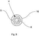
- FIG. 9 shows a cross section through a screw head 16 at the level of the predetermined breaking point 7 of an inventive screw 1 with Einbringpfosten 6.
- the recess 4 of the screw head 16 has a contour 5 in the form of a hexalobular. After removal of the Einbringpfostens 6, the screw 1 on the contour 5 with the matching tool 12 (in Fig. 9 not shown) further screwed or turned off.
Landscapes
- Health & Medical Sciences (AREA)
- Orthopedic Medicine & Surgery (AREA)
- Surgery (AREA)
- Life Sciences & Earth Sciences (AREA)
- Heart & Thoracic Surgery (AREA)
- Nuclear Medicine, Radiotherapy & Molecular Imaging (AREA)
- Engineering & Computer Science (AREA)
- Biomedical Technology (AREA)
- Medical Informatics (AREA)
- Molecular Biology (AREA)
- Animal Behavior & Ethology (AREA)
- General Health & Medical Sciences (AREA)
- Public Health (AREA)
- Veterinary Medicine (AREA)
- Neurology (AREA)
- Surgical Instruments (AREA)
Description
- Die Erfindung betrifft Schrauben mit einem Einbringpfosten sowie Verfahren zur Herstellung von Schrauben mit einem Einbringpfosten gemäss dem Oberbegriff der unabhängigen Ansprüche.
- Nachfolgend wird die Erfindung der Einfachheit halber anhand von Knochenschrauben beschrieben. Dies soll aber auf keinen Fall einschränkend verstanden werden. Die erfindungsgemässen Schrauben können auch in anderen Gebieten, in welchen Schrauben benötigt werden, zum Einsatz kommen.
- Schrauben kommen zum Einsatz, wo Einzelteile aneinander fixiert werden sollen. So werden beispielsweise Knochenteile nach einem Bruch mit Knochenschrauben fixiert. Oftmals kommen dabei auch Knochenplatten zum Einsatz, welche mit Hilfe von Schrauben an den Knochen fixiert werden.
- Beim Eindrehen von Schrauben besteht die Gefahr, dass die Schraube so fest eingedreht wird, dass Teile der Schraube oder des Knochens beschädigt werden. Dadurch kann es vorkommen, dass die Funktion der Schraube nicht mehr gewährleistet ist. Zudem kann der Antrieb beschädigt werden, wodurch ein Entfernen der Schraube durch Ausdrehung nicht mehr sichergestellt werden kann. Dies kann gerade auch bei einer maschinellen Eindrehung geschehen, bei welcher die Drehmomentzunahme weniger bzw. nicht vom Benutzer bemerkt wird.
-
FR 2 768 781 A1 - Die
WO 97/27812 - Ein Teil des Eindrehwerkzeugs verbleibt mit dem Schraubenkopf verbunden. Die Bruchstelle kann dabei rau sein und umliegendes Gewebe reizen oder beschädigen. Zudem verhindert die Bruchkontur, dass ein herkömmliches Ausdrehwerkzeug in den Schraubenkopf eingeführt werden kann, wenn die Schraube wieder gelöst werden soll. Um die Schraube zu entfernen wird daher ein Spezialwerkzeug benötigt. Solche Spezialwerkzeuge sind zum einen sehr teuer, zum anderen sind sie bei den auf Explantationen spezialisierten Ärzten nicht immer vorhanden.
- Es ist daher die Aufgabe der vorliegenden Erfindung, eine Schraube bereitzustellen, welche die Nachteile des bekannten Standes der Technik verhindert. Insbesondere ist es die Aufgabe der vorliegenden Erfindung eine Schraube bereitzustellen, bei welcher die Bruchstelle das umliegende Gewebe nicht beschädigen kann und welche einfach wieder lösbar ist.
- Erfindungsgemäss wird das Problem gemäss den Merkmalen der unabhängigen Ansprüche gelöst. Dabei wird eine Schraube, insbesondere eine Knochenschraube, mit einem Kopf, einem Schaft und einer Spitze vorgeschlagen. Die Schraube weist auf der Kopfseite eine Ausnehmung mit einer Kontur auf. Eine Gegenkontur eines Werkzeugs ist mit der Kontur der Ausnehmung in Wirkverbindung bringbar. Die Schraube ist ausserdem in der Ausnehmung mit einem Einbringpfosten versehen. Dabei ist der Einbringpfosten über eine Sollbruchstelle mit der Knochenschraube verbunden. Die Sollbruchstelle ist innerhalb der Ausnehmung so angeordnet, dass nach Bruch und Entfernung des Einbringpfostens eine Drehmomentübertragung zwischen dem Werkzeug und der Schraube über die Kontur und Gegenkontur möglich ist.
- Die Schraubenspitze beschreibt allgemein das entgegengesetzte Ende der Kopfseite der Schraube. Die Schraubenspitze muss dabei nicht zwingend spitz ausgebildet sein, sondern kann z.B. auch abgerundet oder abgeflacht ausgebildet sein.
- Der Kopf der Schraube beschreibt allgemein ein Endstück der Schraube, welches die Ausnehmung aufweist. Der Schraubenkopf muss dabei nicht zwingend als Querschnittserweiterung gegenüber dem Schaft ausgebildet sein. Der Schaft und der Kopf können auch denselben oder sogar einen kleineren Querschnitt aufweisen.
- Der Schaft der Schraube ist dabei zumindest teilweise mit einem Gewinde versehen. Eine Steigung des Gewindes ist je nach Funktion der Schraube wählbar. Es ist auch möglich, dass die Schraube ein Gewinde mit mehreren Steigungen aufweist. Das Gewinde verläuft vorzugsweise bis in die Spitze. Das Gewinde kann selbstbohrend oder nicht selbstbohrend ausgebildet sein.
- Die Kontur der Ausnehmung ist so ausgebildet, dass sie eine Momentübertragung mit der Gegenkontur des Werkzeuges ermöglicht. Vorzugsweise ist die Kontur dabei als Innenkontur und die Gegenkontur als Aussenkontur ausgebildet.
- Alternativ ist denkbar, dass die Kontur als Aussenkontur ausbildet ist. Dabei ist die Kontur beispielsweise als Stift in der Ausnehmung ausgebildet. Die Gegenkontur kann bei dieser Ausbildung als Innenkontur ausgebildet sein, welche über den Stift gestülpt wird.
- Innerhalb der Ausnehmung ist die Schraube über eine Sollbruchstelle mit einem Einbringpfosten verbunden. Die Verbindung ist dabei über die Sollbruchstelle indirekt ausgebildet.
- Als direkte Verbindung wird verstanden, wenn die Sollbruchstelle das einzige Verbindungsstück zwischen Einbringpfosten und Schraube darstellt.
- Als indirekte Verbindung wird verstanden, wenn die Verbindung erst über eine Pfostenspitze zustande kommt.
- Als Pfostenspitze wird vorliegend ein Endstück des Einbringpfostens verstanden, welches durch ein Brechen der Sollbruchstelle vom restlichen Einbringpfosten getrennt werden kann.
- Die vorgeschlagene Schraube kann über den Einbringpfosten eingedreht werden. Während des Eindrehens nimmt das Drehmoment zu. Sobald ein gewisses Drehmoment erreicht ist, bricht der Einbringpfosten an der Sollbruchstelle. Dadurch wird zumindest ein Teil des Einbringpfostens, welcher von der Sollbruchstelle in Richtung Kopfseite zeigt, von der Schraube gelöst.
- Vorzugsweise erfolgt der Bruch der Sollbruchstelle, bevor die Endstellung der Schraube erreicht wird. Über die Kontur der Ausnehmung kann die Schraube danach mit dem Werkzeug in die Endposition gedreht werden.
- Alternativ ist die Einheit Einbringpfosten-Schraube so konzipiert, dass die Sollbruchstelle bricht, sobald die Schraube ihre Endposition eingenommen hat.
- Die Sollbruchstelle verhindert dabei, dass ein zu grosses Drehmoment entsteht. Indem das Drehmoment nicht zu gross werden kann, wird verhindert, dass der Knochen und/oder die Schraube (z.B. die Kontur der Schraube) oder eine allfällige Platte, welche mit der Schraube befestigt wird, beschädigt wird. Dadurch wird sichergestellt, dass die Schraube ihre Fixierungsaufgabe wahrnehmen kann. Des Weiteren wird mit einer unbeschädigten Kontur sichergestellt, dass die Schraube einfach wieder lösbar ist, sobald die Fixierung nicht mehr benötigt wird.
- Alternativ kann die Sollbruchstelle durch Abbrechen (Biegemoment) statt Abdrehen (Torsionsmoment) gebrochen werden. Dies geschieht vorzugsweise, bevor eine Endstellung der Schraube erreicht wird. Die Endstellung kann danach wiederum über die Kontur der Ausnehmung und die Gegenkontur des Werkzeugs erreicht werden.
- Das Werkzeug kann, wie vorgängig beschrieben, dazu dienen, die Schraube in die Endposition zu bringen. Das Werkzeug dient aber auch dazu, die Schraube wieder zu lösen, z.B. wenn die Fixierung nicht mehr benötigt wird. Dazu ist eine Drehmomentübertragung zwischen der Gegenkontur des Werkzeugs und der Kontur der Ausnehmung nötig. Die Sollbruchstelle zwischen Schraube und Einbringpfosten ist so versenkt innerhalb der Ausnehmung angeordnet, dass nach dem Bruch an der Sollbruchstelle und einer Entfernung des abgebrochenen Endes des Einbringpfostens eine Drehmomentübertragung zwischen der Kontur der Ausnehmung und der Gegenkontur des Werkzeugs möglich ist.
- Die Sollbruchstelle ist daher versenkt gegenüber der Kopfseite der Schraube angeordnet, insbesondere ist die Sollbruchstelle um mehr als 50 % einer Länge der Ausnehmung versenkt angeordnet, besonders bevorzugt ist die Sollbruchstelle ungefähr auf einem Niveau einer Grundfläche der Ausnehmung, bevorzugt genau auf dem Niveau der Grundfläche der Ausnehmung, angeordnet. Die Sollbruchstelle ist dabei innerhalb der Schraube angeordnet. Dadurch wird umliegendes Gewebe nach Brechen der Sollbruchstelle nicht durch die Bruchstelle irritiert, wodurch Reizung und/oder Beschädigung des Gewebes verhindert wird. Ausserdem ist die Kontur für das Werkzeug zugänglich.
- Bevorzugt ist die Sollbruchstelle auf der der Schraubenspitze zugeordneten Seite der Kontur angeordnet. Eine derartige Anordnung hat zur Folge, dass die gesamte Kontur nach Bruch der Sollbruchstelle und Entfernung des Einbringpfostens nicht von der Sollbruchstelle und/oder der allfälligen Pfostenspitze bedeckt ist. Dadurch ist auch die gesamte Kontur für die Gegenkontur des Werkzeugs frei zugänglich. Dies ermöglicht eine gute Drehmomentübertragung zwischen Werkzeug und Schraube. Weiter ist die Sollbruchstelle bei einer derartigen Anordnung von der Kopfseite der Schraube mindestens über die gesamte Länge der Kontur getrennt. Die Sollbruchstelle ist dadurch in keinerlei Kontakt mit dem umliegenden Gewebe.
- Bevorzugt weist die Ausnehmung anschliessend an die Kontur gegen die Schraubenspitze hin eine Öffnung für eine Montage des Einbringpfostens auf. Die Pfostenspitze kann dabei in der Öffnung montiert werden. Die Öffnung ist bevorzugt mit kleinerem Durchmesser als die Ausnehmung mit der Kontur ausgebildet. Die Öffnung weist bevorzugt eine andere Kontur als die Kontur der Ausnehmung auf. Die Sollbruchstelle ist dabei bevorzugt am Übergang zwischen der Öffnung zur Montage des Einbringpfostens und der Kontur, d.h. ungefähr auf dem Niveau der Grundfläche der Ausnehmung, angeordnet.
- Die Sollbruchstelle kann auch innerhalb der Öffnung, d.h. unter dem Niveau der Grundfläche der Ausnehmung, angeordnet sein.
- Alternativ ist die Sollbruchstelle am unteren Ende der Ausnehmung mit Kontur ausgebildet. Dadurch ist die Kontur immer noch zu grossen Teilen unbedeckt und eine Drehmomentübertragung zwischen Werkzeug und Schraube immer noch gut möglich.
- Im Zusammenhang mit der vorliegenden Erfindung sind auch kanülierte Schrauben denkbar. Dabei ist ein Durchgangsloch in der Schraube ausgebildet. Kanülierte Schrauben sind sowohl für Schrauben mit oder ohne Öffnung zur Montage des Einbringpfostens denkbar. Die Durchgangsöffnung besitzt bevorzugt einen kleineren Durchmesser als die Ausnehmung und die Öffnung zur Montage des Einbringpfostens. Alternativ ist die Öffnung zur Montage Teil der Durchgangsöffnung. Durch die Kanülierung kann die Schraube beispielsweise über einen zuvor im Knochen gesetzten Draht (z.B. K-wire) eingebracht werden.
- Bevorzugt ist die Sollbruchstelle als Materialschwächung mit reduziertem Torsionsbruch- und Biegebruchmoments, bevorzugt in Form einer Einschnürung, ausgebildet. Die Sollbruchstelle ist dadurch schwächer ausgebildet als der Einbringpfosten, zumindest an einem in Richtung Kopfseite zeigenden und an die Sollbruchstelle anliegenden Abschnitt. Vorzugsweise ist die Sollbruchstelle schwächer als der gesamte restliche Einbringpfosten. Über Dimension und/oder Form und/oder Material der Sollbruchstelle kann bestimmt werden, bei welchem Drehmoment die Sollbruchstelle bricht.
- Die Sollbruchstelle ist vorzugsweise aus demselben Material, vorzugsweise Titan, Titanlegierung, Implantatstahl, resorbierbarem metallischen oder nichtmetallischen Material, wie die umgebenden Stellen des Einbringpfostens ausgebildet.
- Die Sollbruchstelle kann beispielsweise durch einen spanabhebenden Prozess zustande kommen.
- Alternativ kann die Sollbruchstelle auch aus einem anderen Material ausgebildet sein. So ist beispielsweise denkbar, dass der Einbringpfosten bis auf die Sollbruchstelle weitgehend aus Metall gefertigt ist, die Sollbruchstelle jedoch aus Kunststoff, einem Klebstoff, einem anderen Metall oder einem anderweitigen Material, welches ein reduziertes Torsionsbruch- und/oder Biegebruchmoment aufweist, besteht. Die Sollbruchstelle kann in diesem Fall auch ohne Einschnürung ausgebildet sein.
- Der Einbringpfosten ist einteilig über die Sollbruchstelle mit einer Pfostenspitze versehen. Die Pfostenspitze lässt sich dabei bevorzugt in der Öffnung zur Montage des Einbringpfostens montieren.
- Einteilig ausgebildet heisst, dass der Einbringpfosten mit Sollbruchstelle und Pfostenspitze aus einem Stück angefertigt ist. Die Pfostenspitze kann so in der Ausnehmung, bevorzugt in der Öffnung, montiert werden, dass ein Drehmoment zum Eindrehen der Schraube über die Pfostenspitze auf die Schraube übertragbar ist. Dabei weist die Pfostenspitze bevorzugt eine Pfostenspitzenkontur zur Drehmomentsübertragung auf eine Pfostenspitzengegenkontur auf. Die Pfostenspitze verbleibt nach dem Bruch vorzugsweise in der Schraube.
- Eine einteilige Ausbildung ist einfach herzustellen, da keine Teile zusammengefügt werden müssen. Die Pfostenspitzenkontur und die Sollbruchstelle werden vorzugsweise in den Einbringpfosten eingearbeitet.
- Vorzugsweise ist die Sollbruchstelle so ausgelegt, dass sie bei einem Abdrehmoment bricht, welches kleiner oder gleich dem üblichen Anzugsmoment dieser Schraube ist.
- Typischerweise wird bei medizinischen Anwendungen beim Eindrehvorgang des Schaftes der Schraube dieses Abdrehmoment noch nicht erreicht. Es wird üblicherweise erreicht, sobald die Schraube ihre Endposition erreicht hat, also in der Regel wenn ein Kopf oder ein Endstück der Schraube auf eine Knochenplatte oder den Knochen trifft. Bei diesem Moment werden der Knochen und/oder die Schraube noch nicht beschädigt. Die Sollbruchstelle ist daher so konzipiert, dass zum einen eine Endstellung der Schraube durch Eindrehen mit dem Einbringpfosten erreicht wird, zum anderen aber keine Schäden am Knochen und/oder an der Schraube auftreten.
- Alternativ sind je nach Anwendung höhere oder tiefere Drehmomente denkbar.
- In einer bevorzugten Ausführungsform ist der Einbringpfosten mit der Pfostenspitze in die Öffnung zur Montage des Einbringpfostens eingepresst.
- Dabei wird der Einbringpfosten vorzugsweise mit einteiliger Pfostenspitze in die Öffnung gepresst. Über die Pfostenspitze ist eine Momentübertragung vom Einbringpfosten auf die Schraube möglich.
- Durch das Einpressen kann eine stabile Verbindung hergestellt werden, welche keine zusätzlichen Verbindungselemente benötigt.
- In einer weiteren alternativen, bevorzugten Ausführungsform wird der Einbringpfosten in die Öffnung eingeschraubt. Dabei ist die Pfostenspitze zumindest teilweise mit einem Gewinde versehen, welches in ein Gegengewinde der Öffnung verschraubt werden kann. Dadurch ist die Pfostenspitze nach dem Einschrauben in der Öffnung angeordnet. Im Falle einer kanülierten Schraube kann diese Öffnung jedoch als Durchgangsloch mit zumindest einem teilweisen Gewinde ausgebildet sein.
- Eine Schraubverbindung stellt eine stabile, lösbare Verbindung dar, welche keine zusätzlichen Verbindungselemente benötigt. Die Sollbruchstelle ist bevorzugt direkt anschliessend an das Gewinde der Pfostenspitze ausgebildet. Das Anzugsmoment für die Gewindeverbindung wird hierbei so hoch gewählt, dass es höher als das Ein- bzw. Ausdrehmoment für den Schraubenschaft jedoch kleiner als das Abdrehmoment der Sollbruchstelle ist. Somit ist ein Lösen der Schraube ohne Zerstörung der Sollbruchstelle während der Implantation möglich, z.B. wenn festgestellt wird, dass die Schraube noch nicht an der optimalen Stelle sitzt. Für eine Erhöhung des Anzugsmoments wird eine zur Schraubverbindung zusätzliche Pressverbindung verwendet.
- Dabei wird der eingeschraubte Einbringpfosten vorzugsweise zusätzlich von aussen verpresst.
- Es kann auch eine Kombination der vorstehend beschriebenen Verbindungsmöglichkeiten verwendet werden.
- Bevorzugt ist die Kontur der Ausnehmung als Schlitz, Kreuzschlitz, Innenmehrkant, Innenvielrund oder Phillipps, besonders bevorzugt als Sechskant oder Innensechsrund ("Torx"), d.h. als standardisierte oder genormte Kontur, ausgebildet. Sowohl Sechskant als auch Innensechsrund bilden zuverlässige Möglichkeiten der Momentübertragung.
- Mit diesen bevorzugten Konturen wird kein Spezialwerkzeug benötigt, um die Schraube wieder zu lösen oder nach dem Bruch der Sollbruchstelle fester anzuziehen. Da Spezialwerkzeuge meist teuer in der Herstellung -und im Ankauf- sind, ist eine Lösung mit Konturen wie Sechskant oder Innensechsrund kostengünstiger. Zudem sind Spezialwerkzeuge nicht immer vorhanden und das Anziehen, und vor allem auch das Ausdrehen bei der Explantation in einer Klinik/Praxis, die nicht über die entsprechenden Werkzeuge verfügt wäre in diesem Fall nicht bzw. nur schwer möglich.
- Vorzugsweise weist der Einbringpfosten zusätzlich eine Einbringkontur zur Momentenübertragung einer handelsüblichen, (medizinischen) Bohrmaschine auf.
- Die Einbringkontur kann auch als Griff, wie beispielsweise von Schraubendrehern bekannt, ausgebildet sein.
- Alternativ ist keine spezielle zusätzliche Kontur ausgebildet und die Momentübertragung auf den Einbringpfosten findet ohne zusätzliche Kontur z.B. rein reibschlüssig über das Backenfutter einer Bohrmaschine statt.
- Bevorzugt bestehen die verschiedenen Teile des Einbringpfostens und der Schraube aus Titan, Titanlegierung, Implantatstahl, resorbierbarem metallischem oder nichtmetallischem Material.
- Insbesondere die Pfostenspitze kann aus resorbierbarem Material bestehen. Die Pfostenspitze verbleibt nach dem Bruch der Sollbruchstelle vorzugsweise in der Schraube. Falls die Schraube als Knochenschraube verwendet wird, bleibt die Pfostenspitze daher im Körper. Falls die Pfostenspitze die Kontur der Ausnehmung noch teilweise bedeckt, wird durch die Resorption die ganze Kontur wieder frei. Dies führt dazu, dass das Werkzeug mit der Gegenkontur zur Entfernung der Schraube bei der Explantation besser mit der Kontur in Wirkverbindung treten kann. Dadurch wird ein Lösen der Schraube erleichtert.
- Bevorzugt enthält der Einbringpfosten eine produktspezifische Kennzeichnung, vorzugsweise eine Lotnr, einen Barcode oder ein Logo. Die produktspezifisch Kennzeichnung kann nach dem Bruch der Sollbruchstelle ausgelesen und/oder aufbewahrt werden.
- Durch die Kennzeichnung ist die implantierte Schraube in Kenntnis des abgetrennten Einbringpfostens im Nachhinein identifizierbar.
- Ein weiterer Aspekt der Erfindung betrifft ein Set mit mindestens einer erfindungsgemässen Schraube und einem Werkzeug, das eine zur Kontur der Ausnehmung komplementäre Gegenkontur der Schraube aufweist.
Ein weiterer Aspekt der Erfindung betrifft ein Set mit wenigstens einer Knochenplatte und wenigstens einer erfindungsgemässen Schraube wie vorgängig beschrieben. - Die Schraube(n) dient dabei vorzugsweise der Fixierung der Knochenplatte(n) am Knochen. Die Schraube(n) und die Knochenplatte(n) können dabei eine Verblockungskontur oder ein Gewinde aufweisen, wodurch die Schraube in der Platte verblockt werden kann. Details der Verblockung sind z.B. in der
EP 1 608 278 A1 beschrieben, deren Inhalt hier durch Referenz aufgenommen wird. - Vorzugsweise umfasst dieses Set zusätzlich mindestens ein Werkzeug mit einer zur Kontur der Ausnehmung komplementären Gegenkontur. Mit dem Werkzeug kann die Schraube beispielsweise nach dem Abbrechen des Einbringpfostens noch fester angezogen oder/und nach Verheilung eines Knochenbruchs wieder gelöst und entfernt werden.
- Des Weiteren betrifft die Erfindung ein Verfahren zur Herstellung einer Schraube mit einem Einbringpfosten gemäß Anspruch 14. Es umfasst folgende Schritte:
- Bereitstellen eines Schraubenkörpers mit einem Schraubenkopf, Schaft und Schraubenspitze, wobei der Schraubenkörper eine Ausnehmung mit einer Kontur und anschliessender Öffnung zur Aufnahme des Einbringpfostens aufweist,
- Bereitstellung eines Einbringpfostens, welcher über eine Sollbruchstelle mit einer Pfostenspitze verbunden ist
- Zusammenfügen des Einbringpfostens und des Schraubenkörpers über die Pfostenspitze und die Öffnung zur Aufnahme des Einbringpfostens.
- In einem bevorzugten Verfahren wird der Einbringpfosten in den Schraubenkörper eingeschraubt. Bevorzugt ist der Einbringpfosten zusätzlich von aussen mit dem Schraubenkörper verpresst.
- Alternativ kann der Einbringpfosten auch nur in den Schraubenkörper eingepresst werden.
- Bevorzugt wird der Einbringpfosten mit einer Kombination der beschriebenen Methoden mit dem Schraubenkörper verbunden.
- Weitere vorteilhafte Ausgestaltungen der Erfindung ergeben sich aus der nachfolgenden Beschreibung der Ausführungsbeispiele in Kombination mit den schematischen Figuren. Es zeigen schematisch:
- Figuren 1a/b:
- Einen Längsschnitt durch eine erste Ausführungsform einer erfindungsgemässe Schraube.
- Figur 2:
- Einen Längsschnitt durch eine alternative Schraube.
- Figur 3:
- Einen Längsschnitt durch eine weitere Ausführungsform einer erfindungsgemässen Schraube.
- Figur 4:
- Einen Längsschnitt durch eine weitere Schraube.
- Figuren 5a/b/c:
- Detailansichten von erfindungsgemässen Einbringpfosten mit unterschiedlichen Sollbruchstellen.
- Figur 6:
- eine erfindungsgemässe Schraube nach dem Abdrehen/Abbrechen des Einbringpfostens mit Werkzeug.
- Figur 7:
- einen Längsschnitt durch eine erste Ausführungsform einer erfindungsgemässen Schraube nach dem Abdrehen/Abbrechen des Einbringpfostens mit Werkzeug.
- Figur 8:
- einen Längsschnitt durch eine alternative Ausführungsform einer erfindungsgemässen Schraube nach dem Abdrehen/Abbrechen des Einbringpfostens mit Werkzeug.
- Figur 9:
- einen Querschnitt durch einen Schraubenkopf einer erfindungsgemässen Schraube mit Einbringpfosten.
-
Figuren 1a und 1b zeigen einen Längsschnitt durch eine erste Ausführungsform einer erfindungsgemässen Schraube 1. Die Schraube 1 hat einen Schaft 2, welcher mit einem Gewinde 14 versehen ist. Die Schraube 1 hat zudem eine Spitze 15 und einen der Spitze 15 gegenüberliegenden Schraubenkopf 16. Der Schraubenkopf 16 besitzt eine Kopfseite 3. An der Kopfseite 3ist eine Ausnehmung 4 ausgebildet. Anschliessend an die Ausnehmung 4 ist eine Öffnung 8 zur Aufnahme einer Pfostenspitze 9 eines Einbringpfostens 6 vorhanden. Die Öffnung 8 zur Aufnahme der Pfostenspitze 9 besitzt ein Innengewinde (nicht gezeigt). Die Spitze 9 besitzt ein Aussengewinde (nicht gezeigt), welches in das Innengewinde der Öffnung 8 eingeschraubt werden kann. - In
Figur 1a ist die Pfostenspitze 9 über eine Sollbruchstelle 7 mit einem Pfostenschaft 20 des Einbringpfostens 6 verbunden. Der Pfostenschaft 20 ist in denFiguren 1a und 1b nur teilweise dargestellt. Die Sollbruchstelle 7 ist dabei als Einschnürung zwischen der Spitze 9 und dem Pfostenschaft 20 ausgebildet. Der Einbringpfosten 6 ist daher indirekt über die Sollbruchstelle 7 mit der Schraube 1 verbunden. Die indirekte Verbindung von Pfostenspitze und Schraube kann über ein konisches oder zylindrisches Gewinde, durch Verpressen, Verkleben, Schrumpfen, Crimpen oder andere Verbindungsverfahren erfolgen bzw. als Kombination mehrerer dieser Verbindungsverfahren. Bei einer Verbindung, welche z.B. nur durch Verpressen, Verkleben, Schrumpfen oder Crimpen erfolgt, können die Gewinde auch entfallen. - Bei einem Eindrehen der Schraube 1 erhöht sich das Drehmoment. Die Sollbruchstelle 7 ist so ausgelegt, dass sie vor Erreichen des Anzugsmoments bricht. In
Figur 1b ist der Pfostenschaft 20 des Einbringpfostens 6 an der Sollbruchstelle 7 von der Pfostenspitze 9 abgebrochen. Die Pfostenspitze 9 weist dadurch eine Bruchstelle 18 auf. Die Bruchstelle 18 befindet sich ungefähr auf dem Niveau der Grundfläche 23 der Ausnehmung 4. Dadurch kommt die Bruchstelle 18 nicht in Kontakt mit umliegendem Gewebe, wodurch eine Reizung dieses Gewebes verhindert wird. - Die Ausnehmung 4 besitzt eine Kontur 5. Die Kontur ist als Innensechsrund ausgebildet. Nach Entfernung des Pfostenschafts 20 des Einbringpfostens 6 liegt die Kontur 5 frei. Ein Werkzeug 12 (siehe z.B.
Fig. 6 ) mit einer passenden Gegenkontur 13 (siehe z.B.Fig. 6 ) kann mit der Kontur 5 in Wirkverbindung gebracht werden. Mit Hilfe des Werkzeugs 12 kann die Schraube 1 in eine Endposition eingedreht werden. Die Schraube 1 kann mit Hilfe des Werkzeugs 12 auch ausgedreht werden, sobald die Schraube 1 nicht mehr benötigt wird. -
Figur 2 zeigt eine alternative Schraube 1. Der Einbringpfosten 6 und die Schraube 1 sind dabei einstückig ausgebildet. Beide Teile sind aus einem Stück Material angefertigt. Die Sollbruchstelle 7 bildet dabei direkt die Verbindungsstelle zwischen dem Einbringpfosten 6 und der Schraube 1. Nach einem Abbrechen des Einbringpfostens 6 an der Sollbruchstelle 7, wird sich eine Bruchstelle 8 wiederum ungefähr auf dem Niveau der Grundfläche 23 der Ausnehmung 4 befinden (nicht gezeigt). Die Ausnehmung besitzt wiederum eine Kontur 5, über welche mit Hilfe des Werkzeugs 12 (nicht gezeigt) nach Abbrechen der Sollbruchstelle 7 die Schraube 1 weiter eingedreht oder ausgedreht werden kann. -
Figur 3 zeigt eine weitere Ausführung einer erfindungsgemässen Schraube 1. Die Schraube 1 und der Einbringpfosten sind wie in der Ausführungsform derFiguren 1a und 1b indirekt über die Sollbruchstelle 7 verbunden. Die Schraube 1 ist in dieser Ausführungsform kanüliert. Die Kanülierung 19 erstreckt sich dabei über den gesamten Schaft 2 der Schraube 1. Auch der Einbringpfosten weist eine Kanülierung 21 auf. Die Kanülierungen 19, 21 sind bei eingeschraubtem Einbringpfosten 6 in Fluidverbindung. Dadurch ist eine durchgängige Kanülierung vorhanden. - Innerhalb der Kanülierungen 19, 21 befindet sich ein Draht 22, ein sogenannter Kirschner- oder K-wire. Solche Drähte 22 werden in verschiedenen orthopädischen und anderen Operationen verwendet. Der Draht 22 wird in den Knochen eingesetzt. Über die Kanülierung 19, 21 ist die Schraube 1 über den Draht 22 in den Knochen einbringbar. Der Draht 22 dient dabei als Führung.
-
Figur 4 zeigt eine weitere Schraube 1. Wie inFigur 3 ist eine Kanülierung 19 in der Schraube 1 vorhanden. Der Einbringpfosten 6 und die Schraube 1 sind wie inFigur 2 einstückig ausgebildet. Die Kanülierung 19 ist durchgängig durch die Schraube 1 und den Einbringpfosten 6 ausgebildet. Innerhalb der Kanülierung 19 ist wiederum ein Draht 22 gezeigt. Die Schraube 1 wurde wiederum über die Kanülierung 19 und den Draht 22 eingebracht. - Die
Figuren 5a, b, c zeigen Detailansichten von Einbringpfosten 6. Die Einbringpfosten 6 weisen Pfostenspitzen 9 und Pfostenschäfte 20 auf, welche über Sollbruchstellen 7 miteinander verbunden sind. - Bei der in
Figur 5a gezeigten Ausführung ist die Sollbruchstelle 7 als Materialvariation realisiert worden. Die Sollbruchstelle 7 ist daher aus einem bruchschwächeren Material als die Pfostenspitze 9 und der Pfostenschaft 20 gebildet. Die Pfostenspitze 9 und der Pfostenschaft 20 sind z.B. aus Titan gefertigt, die Sollbruchstelle z.B. aus einem biokompatiblen Kunststoff, welcher die beiden Teile verklebt. Dadurch wird die Sollbruchstelle 7 bei einem gewissen Drehmoment brechen. - Bei der in
Figur 5b gezeigten Ausführung ist die Sollbruchstelle 7 als Einschnürung ausgebildet. Die Einschnürung ist durch Materialabtragung an dieser Stelle zustande gekommen. Die Pfostenspitze 9 und der Pfostenschaft 20 sind einteilig ausgebildet. - Bei der in
Figur 5c gezeigten Ausführung ist die Sollbruchstelle durch eine Verbindung mit reduziertem Widerstandsmoment gegen Biegung und Torsion ausgebildet. Solche Verbindungen können beispielsweise Schweissverbindungen sein. Alternative Verbindungen sind Pressverbindungen, Schrumpfverbindungen, Crimpverbindungen, Klebeverbindungen und anderweitige passende Verbindungen, wie auch Kombinationen der Verbindungen. -
Figur 6 zeigt eine erfindungsgemässe Schraube 1 nach Entfernung des Pfostenschafts 20 des Einbringpfostens 6 (nicht gezeigt). In die Ausnehmung 4 (inFig. 6 nicht sichtbar) ist ein Werkzeug 12 eingeführt. Dabei ist eine Gegenkontur 13 des Werkzeugs 12 in Wirkverbindung mit der Kontur 5 (inFig. 6 nicht sichtbar) der Ausnehmung 4 (inFig. 6 nicht sichtbar). Die Schraube 1 kann durch das Werkzeug 12 noch weiter eingedreht werden. Sobald die Schraube nicht mehr benötigt wird oder explantiert werden muss, kann die Schraube mit Hilfe des Werkzeugs 12 gelöst werden. - Die Kontur 5 (nicht sichtbar) der Ausnehmung ist z.B. als Innensechsrund ausgebildet. Diese gängige Kontur stellt sicher, dass die Schraube 1 mit einem standardisierten/genormten Werkzeug 12 weiter eingedreht bzw. ausgedreht werden kann.
- Das Werkzeug 12 besitzt an einem der Gegenkontur 13 gegenüberliegenden Ende einen Verbindungsabschnitt 17. Der Verbindungsabschnitt 17 dient einer Verbindung des Werkzeugs 12 mit einer Eindrehhilfe (nicht gezeigt) wie beispielsweise einer Bohrmaschine oder einem Schraubendrehergriff.
-
Figur 7 zeigt einen Längsschnitt der Schraube 1 derFiguren 1a, b , nachdem der Pfostenschaft 20 des Einbringpfostens 6 (nicht gezeigt) entfernt wurde und das Werkzeug 12 mit der Gegenkontur 13 in die Ausnehmung 4 eingeführt wurde. -
Figur 8 zeigt einen Längsschnitt der Schraube 1 derFigur 3 , nachdem der Pfostenschaft 20 des Einbringpfostens 6 (nicht gezeigt) entfernt wurde und das Werkzeug 12 mit der Gegenkontur 13 in die Ausnehmung 4 eingeführt wurde. -
Figur 9 zeigt einen Querschnitt durch einen Schraubenkopf 16 auf Höhe der Sollbruchstelle 7 einer erfindungsgemässen Schraube 1 mit Einbringpfosten 6. Die Ausnehmung 4 des Schraubenkopfes 16 weist eine Kontur 5 in Form eines Innensechsrundes auf. Nach einer Entfernung des Einbringpfostens 6 kann die Schraube 1 über die Kontur 5 mit dem passenden Werkzeug 12 (inFig. 9 nicht gezeigt) noch weiter eingedreht oder ausgedreht werden.
Claims (16)
- Schraube (1), insbesondere Knochenschraube, mit einem Kopf (16), einem Schaft (2) und einer Spitze (15), wobei die Schraube an einer Kopfseite (3) eine Ausnehmung (4) mit einer Kontur (5) aufweist und in der Ausnehmung (4) mit einem Einbringpfosten (6) versehen ist, der über eine Sollbruchstelle (7) mit der Schraube (1) verbunden ist, wobei eine Gegenkontur (13) eines Werkzeugs (12) nach dem Bruch der Sollbruchstelle mit der Kontur (5) der Ausnehmung (4) in Wirkverbindung bringbar ist,
wobei die Sollbruchstelle (7) innerhalb der Ausnehmung (4) so angeordnet ist, dass nach Entfernung des Einbringpfostens (6) eine Drehmomentübertragung zwischen dem Werkzeug (12) und der Schraube (1) über die Kontur (5) und Gegenkontur (13) möglich ist, wobei der Einbringpfosten (6) einteilig über die Sollbruchstelle (7) mit einer Pfostenspitze (9) versehen ist,
dadurch gekennzeichnet,
dass die Pfostenspitze (9) eine Kontur für eine Drehmomentübertragung über eine Gegenkontur in der Ausnehmung (4) der Schraube (1) aufweist. - Schraube (1) nach Anspruch 1, wobei die Sollbruchstelle (7) versenkt gegenüber der Endfläche (3) der Schraube (1), insbesondere auf dem Niveau der Grundfläche (23) der Kontur (5) der Ausnehmung angeordnet ist.
- Schraube (1) nach einem der Ansprüche 1 und 2, wobei die Ausnehmung (4) anschliessend an die Kontur (5) eine Öffnung (8), vorzugsweise ein Sackloch, aufweist.
- Schraube (1) nach einem der Ansprüche 1 bis 3, wobei die Schraube (1) und der Einbringpfosten (6) eine Kanülierung (19, 21) aufweisen.
- Schraube (1) nach einem der Ansprüche 1 bis 4, wobei die Sollbruchstelle (7) als Materialschwächung in Form einer Einschnürung ausgebildet ist.
- Schraube (1) nach einem der vorhergehenden Ansprüche, wobei die Sollbruchstelle (7) so ausgelegt ist, dass sie bei einem Drehmoment bricht, das kleiner als das Durchdrehmoment des Knochens ist.
- Schraube (1) nach Anspruch 3 oder jedem davon abhängigen Anspruch, wobei der Einbringpfosten (6) in die Öffnung (8) eingeschraubt und zusätzlich verpresst ist.
- Schraube (1) nach Anspruch 3 oder jedem davon abhängigen Anspruch, wobei der Einbringpfosten (6) in die Öffnung (8) der Ausnehmung (4) eingepresst ist.
- Schraube (1) nach einem der vorhergehenden Ansprüche, wobei die Kontur (5) der Ausnehmung (4) als Sechskant oder Innensechsrund, Vierkant, Phillips, etc. ausgebildet ist.
- Schraube (1) nach einem der vorhergehenden Ansprüche, wobei die Schraube (1) und der Einbringpfosten aus einem biokompatiblen Material aus der Liste Titan, Titanlegierungen, Stahl, Kunststoff, resorbierbares Metall oder resorbierbarer Kunststoff bestehen.
- Schraube (1) nach einem der vorhergehenden Ansprüche, wobei der Einbringpfosten (6) eine produktspezifische Kennzeichnung, vorzugsweise eine Lotnr., einen Barcode oder ein Logo, enthält, der nach dem Bruch der Sollbruchstelle (7) ausgelesen und/oder aufbewahrt werden kann.
- Set, mit wenigstens einer Schraube (1) nach einem der Ansprüche 1-11 und einem Werkzeug (12), das eine zur Kontur (5) der Ausnehmung (4) komplementäre Gegenkontur (13) der Schraube (1) aufweist.
- Set nach Anspruch 12, welches zusätzlich eine Knochenplatte umfasst.
- Verfahren zur Herstellung einer Schraube (1) mit einem Einbringpfosten (6), welches die folgenden Schritte umfasst:- Bereitstellen eines Schraubenkörpers (1) mit einem Kopf, einem Schaft (2) und einer Spitze, wobei der Schraubenkörper (1) eine Ausnehmung (4) mit einer Kontur (5) und anschliessender Öffnung (8), vorzugsweise anschliessendem Sackloch, aufweist.- Bereitstellung eines Pfostens (6), welcher über eine Sollbruchstelle (7) mit einer Pfostenspitze (9) verbunden ist, wobei die Pfostenspitze (9) eine Kontur für eine Drehmomentübertragung über eine Gegenkontur in der Ausnehmung (4) der Schraube (1) aufweist- Zusammenfügen des Pfostens (6) und des Schraubenkörpers (1) über die Pfostenspitze (9) und die Öffnung (8).
- Verfahren nach Anspruch 14, wobei der Pfosten (6) in den Schraubenkörper (1) eingeschraubt und zusätzlich verpresst ist.
- Verfahren nach Anspruch 14, wobei der Pfosten (6) in den Schraubenkörper (1) eingepresst wird.
Applications Claiming Priority (2)
| Application Number | Priority Date | Filing Date | Title |
|---|---|---|---|
| DE202014006372.9U DE202014006372U1 (de) | 2014-08-05 | 2014-08-05 | Schraube mit Einbringpfosten |
| PCT/EP2015/067837 WO2016020329A1 (de) | 2014-08-05 | 2015-08-03 | Schraube mit einbringpfosten |
Publications (2)
| Publication Number | Publication Date |
|---|---|
| EP3177223A1 EP3177223A1 (de) | 2017-06-14 |
| EP3177223B1 true EP3177223B1 (de) | 2019-10-16 |
Family
ID=51520204
Family Applications (1)
| Application Number | Title | Priority Date | Filing Date |
|---|---|---|---|
| EP15753326.6A Active EP3177223B1 (de) | 2014-08-05 | 2015-08-03 | Schraube mit einbringpfosten |
Country Status (11)
| Country | Link |
|---|---|
| US (1) | US10582959B2 (de) |
| EP (1) | EP3177223B1 (de) |
| JP (1) | JP6581657B2 (de) |
| CN (1) | CN106572872B (de) |
| AU (1) | AU2015299098B2 (de) |
| BR (1) | BR112017002062B1 (de) |
| CH (1) | CH709980A8 (de) |
| DE (1) | DE202014006372U1 (de) |
| ES (1) | ES2765459T3 (de) |
| MX (1) | MX383615B (de) |
| WO (1) | WO2016020329A1 (de) |
Families Citing this family (25)
| Publication number | Priority date | Publication date | Assignee | Title |
|---|---|---|---|---|
| CN104791353A (zh) * | 2015-04-02 | 2015-07-22 | 张琦 | 一种凸块拧旋杆 |
| US11806250B2 (en) | 2018-02-22 | 2023-11-07 | Warsaw Orthopedic, Inc. | Expandable spinal implant system and method of using same |
| US11666367B2 (en) * | 2018-05-30 | 2023-06-06 | Tushar Goradia | Guidance apparatus for implantation into bone and related methods of use |
| WO2020152783A1 (ja) * | 2019-01-22 | 2020-07-30 | オリンパス株式会社 | 超音波処置具および振動伝達部材 |
| CN109899365B (zh) * | 2019-03-13 | 2021-02-26 | 博瑞康有限公司 | 螺栓 |
| US12239544B2 (en) | 2020-11-05 | 2025-03-04 | Warsaw Orthopedic, Inc. | Rhomboid shaped implants |
| US11564724B2 (en) | 2020-11-05 | 2023-01-31 | Warsaw Orthopedic, Inc. | Expandable inter-body device, system and method |
| US11963881B2 (en) | 2020-11-05 | 2024-04-23 | Warsaw Orthopedic, Inc. | Expandable inter-body device, system, and method |
| US12318308B2 (en) | 2020-11-05 | 2025-06-03 | Warsaw Orthopedic, Inc. | Dual expandable inter-body device |
| US11376134B1 (en) | 2020-11-05 | 2022-07-05 | Warsaw Orthopedic, Inc. | Dual expanding spinal implant, system, and method of use |
| US11833059B2 (en) | 2020-11-05 | 2023-12-05 | Warsaw Orthopedic, Inc. | Expandable inter-body device, expandable plate system, and associated methods |
| US12121453B2 (en) | 2020-11-05 | 2024-10-22 | Warsaw Orthopedic, Inc. | Dual wedge expandable implant with eyelets, system, and method of use |
| US11517443B2 (en) | 2020-11-05 | 2022-12-06 | Warsaw Orthopedic, Inc. | Dual wedge expandable implant, system and method of use |
| US11395743B1 (en) | 2021-05-04 | 2022-07-26 | Warsaw Orthopedic, Inc. | Externally driven expandable interbody and related methods |
| US11638653B2 (en) | 2020-11-05 | 2023-05-02 | Warsaw Orthopedic, Inc. | Surgery instruments with a movable handle |
| US12171439B2 (en) | 2020-11-05 | 2024-12-24 | Warsaw Orthopedic, Inc. | Protected drill |
| US12295865B2 (en) | 2021-06-24 | 2025-05-13 | Warsaw Orthopedic, Inc. | Expandable interbody implant and corresponding inserter |
| US12485019B2 (en) | 2021-06-24 | 2025-12-02 | Warsaw Orthopedic, Inc. | Parallel jaw inserter |
| US12440349B2 (en) | 2021-11-01 | 2025-10-14 | Warsaw Orthopedic, Inc. | Expandable interbody implant and breakoff screw |
| WO2022271280A1 (en) | 2021-06-24 | 2022-12-29 | Warsaw Orthopedic, Inc. | Expandable interbody implant and corresponding surgical tool |
| US12268614B2 (en) | 2021-06-24 | 2025-04-08 | Warsaw Orthopedic, Inc. | Interbody implant with adjusting shims |
| US11612499B2 (en) | 2021-06-24 | 2023-03-28 | Warsaw Orthopedic, Inc. | Expandable interbody implant |
| WO2023084653A1 (ja) * | 2021-11-10 | 2023-05-19 | オリンパスメディカルシステムズ株式会社 | 締結部材、超音波処置具の製造方法、及び超音波処置具 |
| US11850163B2 (en) | 2022-02-01 | 2023-12-26 | Warsaw Orthopedic, Inc. | Interbody implant with adjusting shims |
| US12533241B2 (en) | 2023-05-16 | 2026-01-27 | Warsaw Orthopedic, Inc. | Distracting and angling expandable interbody device |
Family Cites Families (24)
| Publication number | Priority date | Publication date | Assignee | Title |
|---|---|---|---|---|
| DE4323434C1 (de) | 1993-07-13 | 1995-02-16 | Arcus Elektrotech | Abscherschraube |
| DE19603410C2 (de) * | 1996-01-31 | 1999-02-18 | Kirsch Axel | Schraube zum Einsetzen in einen Knochen sowie Ausdrehwerkzeug dafür |
| JP3035567B2 (ja) * | 1997-01-31 | 2000-04-24 | 洋司 村嶋 | キャニュレイテッドスクリュー |
| FR2768781B1 (fr) * | 1997-09-25 | 2000-01-07 | Groupe Lepine | Ensemble de vis et de mandrin relies l'un a l'autre par un pont secable |
| FR2781998B1 (fr) * | 1998-08-07 | 2000-11-10 | Hassan Razian | Element prothetique, implantable dans un os, a tete de manipulation separable |
| US5971987A (en) * | 1998-09-18 | 1999-10-26 | Ethicon, Inc. | Biocompatible absorbable polymer fastener and driver for use in surgical procedures |
| WO2002054935A2 (en) * | 2000-12-29 | 2002-07-18 | Thomas James C Jr | Vertebral alignment system |
| US6723099B1 (en) * | 2001-11-08 | 2004-04-20 | Biomet, Inc. | Three sided tack for bone fixation |
| US20030125749A1 (en) * | 2001-12-27 | 2003-07-03 | Ethicon, Inc. | Cannulated screw and associated driver system |
| ATE450221T1 (de) | 2003-04-03 | 2009-12-15 | Medartis Ag | Aufnahme für ein verblockungselement und verblockungselement |
| US7354442B2 (en) * | 2003-05-05 | 2008-04-08 | Warsaw Orthopedic, Inc. | Bone anchor and methods of using the same |
| JP2006006822A (ja) * | 2004-06-29 | 2006-01-12 | Takiron Co Ltd | 生体骨用スクリュー |
| US7846167B2 (en) * | 2005-11-07 | 2010-12-07 | Biomet Microfixation, Llc | Driver assembly and fastener apparatus |
| US20070218750A1 (en) * | 2006-03-17 | 2007-09-20 | Nexa Orthopedics, Inc. | Snap-off screw with recessed breakoff area |
| US20070270859A1 (en) * | 2006-04-28 | 2007-11-22 | Sdgi Holdings, Inc. | Orthopedic screw with break away drive |
| DE102009003177B4 (de) | 2009-05-18 | 2014-02-13 | Peter Lazic Gmbh | Implantat zur Fixierung nebeneinander angeordneter Knochenplatten |
| DE102010016812A1 (de) | 2009-06-08 | 2011-03-17 | Z.-Medical Gmbh & Co. Kg | Knochenschraube |
| AU2010303934B2 (en) * | 2009-10-05 | 2014-03-27 | Roger P. Jackson | Polyaxial bone anchor with non-pivotable retainer and pop-on shank, some with friction fit |
| CN201642299U (zh) * | 2010-05-24 | 2010-11-24 | 范存义 | 一种自钻式可折断骨片钉 |
| DE102011001264A1 (de) * | 2011-03-14 | 2012-09-20 | Aesculap Ag | Chirurgischer K-Draht und chirurgisches Schraubensystem |
| DE102012104973A1 (de) | 2011-09-22 | 2013-03-28 | Zbigniew Combrowski | Chirurgisches Instrument |
| FR2983396B1 (fr) | 2011-12-05 | 2014-06-27 | Fournitures Hospitalieres Ind | Dispositif d'osteosynthese notamment pour correction d'une deformation d'un orteil et ancillaire pour la mise en place de celui-ci |
| ES2539501T3 (es) * | 2012-06-18 | 2015-07-01 | Biedermann Technologies Gmbh & Co. Kg | Anclaje óseo |
| AT513515B1 (de) | 2013-03-06 | 2014-05-15 | Arnetzl Gerwin Vincent Dr | Schraubvorrichtung für eine Kopfschraube zum Befestigen eines Abutments für einen Zahnaufbau an einem Implantatkörper |
-
2014
- 2014-08-05 DE DE202014006372.9U patent/DE202014006372U1/de not_active Expired - Lifetime
- 2014-08-15 CH CH01230/14A patent/CH709980A8/de not_active Application Discontinuation
-
2015
- 2015-08-03 WO PCT/EP2015/067837 patent/WO2016020329A1/de not_active Ceased
- 2015-08-03 MX MX2017001663A patent/MX383615B/es unknown
- 2015-08-03 CN CN201580043404.1A patent/CN106572872B/zh not_active Expired - Fee Related
- 2015-08-03 JP JP2017526759A patent/JP6581657B2/ja active Active
- 2015-08-03 AU AU2015299098A patent/AU2015299098B2/en active Active
- 2015-08-03 BR BR112017002062-9A patent/BR112017002062B1/pt active IP Right Grant
- 2015-08-03 EP EP15753326.6A patent/EP3177223B1/de active Active
- 2015-08-03 ES ES15753326T patent/ES2765459T3/es active Active
- 2015-08-03 US US15/329,385 patent/US10582959B2/en active Active
Non-Patent Citations (1)
| Title |
|---|
| None * |
Also Published As
| Publication number | Publication date |
|---|---|
| MX383615B (es) | 2025-03-14 |
| MX2017001663A (es) | 2017-04-27 |
| JP6581657B2 (ja) | 2019-09-25 |
| BR112017002062A2 (pt) | 2017-12-26 |
| BR112017002062B1 (pt) | 2022-05-03 |
| US10582959B2 (en) | 2020-03-10 |
| AU2015299098A1 (en) | 2017-03-16 |
| CH709980A2 (de) | 2016-02-15 |
| CN106572872B (zh) | 2020-05-29 |
| DE202014006372U1 (de) | 2014-08-22 |
| CN106572872A (zh) | 2017-04-19 |
| EP3177223A1 (de) | 2017-06-14 |
| ES2765459T3 (es) | 2020-06-09 |
| US20170325862A1 (en) | 2017-11-16 |
| CH709980A8 (de) | 2016-07-15 |
| JP2017523895A (ja) | 2017-08-24 |
| WO2016020329A1 (de) | 2016-02-11 |
| AU2015299098B2 (en) | 2020-02-20 |
Similar Documents
| Publication | Publication Date | Title |
|---|---|---|
| DE202014006372U1 (de) | Schraube mit Einbringpfosten | |
| EP2440147B1 (de) | Chirurgieinstrument mit knochenschraube | |
| EP1096892B1 (de) | Knochenschraube, insbesondere für den einsatz bei translaminärer wirbelverschraubung | |
| DE69430540T2 (de) | Konische knochenschraube mit variierender gewindesteigung | |
| EP1175871B1 (de) | Verriegelungsnagel | |
| DE60206700T2 (de) | Befestigungsvorrichtung für Knochenteile | |
| EP1972297B1 (de) | Kombination eines Abutments und einer zweiteilige Schraube | |
| DE102005021879B4 (de) | Orthopädisches Verankerungselement und Osteosynthesevorrichtung | |
| EP0654248B1 (de) | Kraftübertragungsglied für Osteosynthesearbeiten | |
| DE69415676T2 (de) | Sperrklinken-kompressionseinrichtung | |
| EP2564799B1 (de) | Chirurgischer Mittelfuß-Kompressionsnagel | |
| DE102005021885A1 (de) | Vorrichtung zum Einbringen eines Ankerelements samt Faden in einen Knochen | |
| EP1016382A2 (de) | Schenkelhalsschraube | |
| EP1440664A2 (de) | Implantat für Osteosynthese | |
| CH666176A5 (de) | Einrichtung zur behandlung eines knochens und nagel fuer eine solche einrichtung. | |
| EP0613657A1 (de) | Befestigungsnagel und Setzwerkzeug hierfür | |
| EP0172130A2 (de) | Schraube zur orthopädischen Fixation | |
| WO2007048267A1 (de) | Gewinde formende schraube | |
| DE102008017741B4 (de) | Werkzeug zum Eindrehen und Ausdrehen einer Schraubenfeder in den und aus dem Hohlraum eines Röhrenknochens | |
| DE102017101348A1 (de) | Achsgenauer Schraubendreher | |
| EP1982665B1 (de) | Kompressionsschraube mit Drahtelement | |
| EP0589235B1 (de) | Marknagel mit Arretierungsbolzen | |
| DE2225863A1 (de) | Zahnverankerung | |
| WO1996041573A1 (de) | Selbstbohrendes knochenfixationselement | |
| DE102006007541A1 (de) | Implantat für Zahnersatzbefestigung |
Legal Events
| Date | Code | Title | Description |
|---|---|---|---|
| STAA | Information on the status of an ep patent application or granted ep patent |
Free format text: STATUS: THE INTERNATIONAL PUBLICATION HAS BEEN MADE |
|
| PUAI | Public reference made under article 153(3) epc to a published international application that has entered the european phase |
Free format text: ORIGINAL CODE: 0009012 |
|
| STAA | Information on the status of an ep patent application or granted ep patent |
Free format text: STATUS: REQUEST FOR EXAMINATION WAS MADE |
|
| 17P | Request for examination filed |
Effective date: 20170201 |
|
| AK | Designated contracting states |
Kind code of ref document: A1 Designated state(s): AL AT BE BG CH CY CZ DE DK EE ES FI FR GB GR HR HU IE IS IT LI LT LU LV MC MK MT NL NO PL PT RO RS SE SI SK SM TR |
|
| AX | Request for extension of the european patent |
Extension state: BA ME |
|
| DAV | Request for validation of the european patent (deleted) | ||
| DAX | Request for extension of the european patent (deleted) | ||
| GRAP | Despatch of communication of intention to grant a patent |
Free format text: ORIGINAL CODE: EPIDOSNIGR1 |
|
| STAA | Information on the status of an ep patent application or granted ep patent |
Free format text: STATUS: GRANT OF PATENT IS INTENDED |
|
| INTG | Intention to grant announced |
Effective date: 20190529 |
|
| GRAS | Grant fee paid |
Free format text: ORIGINAL CODE: EPIDOSNIGR3 |
|
| GRAA | (expected) grant |
Free format text: ORIGINAL CODE: 0009210 |
|
| STAA | Information on the status of an ep patent application or granted ep patent |
Free format text: STATUS: THE PATENT HAS BEEN GRANTED |
|
| AK | Designated contracting states |
Kind code of ref document: B1 Designated state(s): AL AT BE BG CH CY CZ DE DK EE ES FI FR GB GR HR HU IE IS IT LI LT LU LV MC MK MT NL NO PL PT RO RS SE SI SK SM TR |
|
| REG | Reference to a national code |
Ref country code: GB Ref legal event code: FG4D Free format text: NOT ENGLISH |
|
| REG | Reference to a national code |
Ref country code: CH Ref legal event code: EP |
|
| REG | Reference to a national code |
Ref country code: DE Ref legal event code: R096 Ref document number: 502015010683 Country of ref document: DE |
|
| REG | Reference to a national code |
Ref country code: IE Ref legal event code: FG4D Free format text: LANGUAGE OF EP DOCUMENT: GERMAN |
|
| REG | Reference to a national code |
Ref country code: AT Ref legal event code: REF Ref document number: 1190531 Country of ref document: AT Kind code of ref document: T Effective date: 20191115 |
|
| REG | Reference to a national code |
Ref country code: CH Ref legal event code: NV Representative=s name: HEPP WENGER RYFFEL AG, CH |
|
| REG | Reference to a national code |
Ref country code: NL Ref legal event code: MP Effective date: 20191016 |
|
| REG | Reference to a national code |
Ref country code: LT Ref legal event code: MG4D |
|
| PG25 | Lapsed in a contracting state [announced via postgrant information from national office to epo] |
Ref country code: GR Free format text: LAPSE BECAUSE OF FAILURE TO SUBMIT A TRANSLATION OF THE DESCRIPTION OR TO PAY THE FEE WITHIN THE PRESCRIBED TIME-LIMIT Effective date: 20200117 Ref country code: NO Free format text: LAPSE BECAUSE OF FAILURE TO SUBMIT A TRANSLATION OF THE DESCRIPTION OR TO PAY THE FEE WITHIN THE PRESCRIBED TIME-LIMIT Effective date: 20200116 Ref country code: BG Free format text: LAPSE BECAUSE OF FAILURE TO SUBMIT A TRANSLATION OF THE DESCRIPTION OR TO PAY THE FEE WITHIN THE PRESCRIBED TIME-LIMIT Effective date: 20200116 Ref country code: PL Free format text: LAPSE BECAUSE OF FAILURE TO SUBMIT A TRANSLATION OF THE DESCRIPTION OR TO PAY THE FEE WITHIN THE PRESCRIBED TIME-LIMIT Effective date: 20191016 Ref country code: SE Free format text: LAPSE BECAUSE OF FAILURE TO SUBMIT A TRANSLATION OF THE DESCRIPTION OR TO PAY THE FEE WITHIN THE PRESCRIBED TIME-LIMIT Effective date: 20191016 Ref country code: LV Free format text: LAPSE BECAUSE OF FAILURE TO SUBMIT A TRANSLATION OF THE DESCRIPTION OR TO PAY THE FEE WITHIN THE PRESCRIBED TIME-LIMIT Effective date: 20191016 Ref country code: PT Free format text: LAPSE BECAUSE OF FAILURE TO SUBMIT A TRANSLATION OF THE DESCRIPTION OR TO PAY THE FEE WITHIN THE PRESCRIBED TIME-LIMIT Effective date: 20200217 Ref country code: FI Free format text: LAPSE BECAUSE OF FAILURE TO SUBMIT A TRANSLATION OF THE DESCRIPTION OR TO PAY THE FEE WITHIN THE PRESCRIBED TIME-LIMIT Effective date: 20191016 Ref country code: NL Free format text: LAPSE BECAUSE OF FAILURE TO SUBMIT A TRANSLATION OF THE DESCRIPTION OR TO PAY THE FEE WITHIN THE PRESCRIBED TIME-LIMIT Effective date: 20191016 Ref country code: LT Free format text: LAPSE BECAUSE OF FAILURE TO SUBMIT A TRANSLATION OF THE DESCRIPTION OR TO PAY THE FEE WITHIN THE PRESCRIBED TIME-LIMIT Effective date: 20191016 |
|
| PG25 | Lapsed in a contracting state [announced via postgrant information from national office to epo] |
Ref country code: IS Free format text: LAPSE BECAUSE OF FAILURE TO SUBMIT A TRANSLATION OF THE DESCRIPTION OR TO PAY THE FEE WITHIN THE PRESCRIBED TIME-LIMIT Effective date: 20200224 Ref country code: HR Free format text: LAPSE BECAUSE OF FAILURE TO SUBMIT A TRANSLATION OF THE DESCRIPTION OR TO PAY THE FEE WITHIN THE PRESCRIBED TIME-LIMIT Effective date: 20191016 Ref country code: RS Free format text: LAPSE BECAUSE OF FAILURE TO SUBMIT A TRANSLATION OF THE DESCRIPTION OR TO PAY THE FEE WITHIN THE PRESCRIBED TIME-LIMIT Effective date: 20191016 |
|
| REG | Reference to a national code |
Ref country code: ES Ref legal event code: FG2A Ref document number: 2765459 Country of ref document: ES Kind code of ref document: T3 Effective date: 20200609 |
|
| PG25 | Lapsed in a contracting state [announced via postgrant information from national office to epo] |
Ref country code: AL Free format text: LAPSE BECAUSE OF FAILURE TO SUBMIT A TRANSLATION OF THE DESCRIPTION OR TO PAY THE FEE WITHIN THE PRESCRIBED TIME-LIMIT Effective date: 20191016 |
|
| REG | Reference to a national code |
Ref country code: DE Ref legal event code: R097 Ref document number: 502015010683 Country of ref document: DE |
|
| PG2D | Information on lapse in contracting state deleted |
Ref country code: IS |
|
| PG25 | Lapsed in a contracting state [announced via postgrant information from national office to epo] |
Ref country code: RO Free format text: LAPSE BECAUSE OF FAILURE TO SUBMIT A TRANSLATION OF THE DESCRIPTION OR TO PAY THE FEE WITHIN THE PRESCRIBED TIME-LIMIT Effective date: 20191016 Ref country code: CZ Free format text: LAPSE BECAUSE OF FAILURE TO SUBMIT A TRANSLATION OF THE DESCRIPTION OR TO PAY THE FEE WITHIN THE PRESCRIBED TIME-LIMIT Effective date: 20191016 Ref country code: EE Free format text: LAPSE BECAUSE OF FAILURE TO SUBMIT A TRANSLATION OF THE DESCRIPTION OR TO PAY THE FEE WITHIN THE PRESCRIBED TIME-LIMIT Effective date: 20191016 Ref country code: DK Free format text: LAPSE BECAUSE OF FAILURE TO SUBMIT A TRANSLATION OF THE DESCRIPTION OR TO PAY THE FEE WITHIN THE PRESCRIBED TIME-LIMIT Effective date: 20191016 Ref country code: IS Free format text: LAPSE BECAUSE OF FAILURE TO SUBMIT A TRANSLATION OF THE DESCRIPTION OR TO PAY THE FEE WITHIN THE PRESCRIBED TIME-LIMIT Effective date: 20200216 |
|
| PLBE | No opposition filed within time limit |
Free format text: ORIGINAL CODE: 0009261 |
|
| STAA | Information on the status of an ep patent application or granted ep patent |
Free format text: STATUS: NO OPPOSITION FILED WITHIN TIME LIMIT |
|
| PG25 | Lapsed in a contracting state [announced via postgrant information from national office to epo] |
Ref country code: SM Free format text: LAPSE BECAUSE OF FAILURE TO SUBMIT A TRANSLATION OF THE DESCRIPTION OR TO PAY THE FEE WITHIN THE PRESCRIBED TIME-LIMIT Effective date: 20191016 Ref country code: SK Free format text: LAPSE BECAUSE OF FAILURE TO SUBMIT A TRANSLATION OF THE DESCRIPTION OR TO PAY THE FEE WITHIN THE PRESCRIBED TIME-LIMIT Effective date: 20191016 |
|
| 26N | No opposition filed |
Effective date: 20200717 |
|
| PG25 | Lapsed in a contracting state [announced via postgrant information from national office to epo] |
Ref country code: SI Free format text: LAPSE BECAUSE OF FAILURE TO SUBMIT A TRANSLATION OF THE DESCRIPTION OR TO PAY THE FEE WITHIN THE PRESCRIBED TIME-LIMIT Effective date: 20191016 |
|
| PG25 | Lapsed in a contracting state [announced via postgrant information from national office to epo] |
Ref country code: MC Free format text: LAPSE BECAUSE OF FAILURE TO SUBMIT A TRANSLATION OF THE DESCRIPTION OR TO PAY THE FEE WITHIN THE PRESCRIBED TIME-LIMIT Effective date: 20191016 |
|
| PG25 | Lapsed in a contracting state [announced via postgrant information from national office to epo] |
Ref country code: LU Free format text: LAPSE BECAUSE OF NON-PAYMENT OF DUE FEES Effective date: 20200803 |
|
| REG | Reference to a national code |
Ref country code: BE Ref legal event code: MM Effective date: 20200831 |
|
| PG25 | Lapsed in a contracting state [announced via postgrant information from national office to epo] |
Ref country code: BE Free format text: LAPSE BECAUSE OF NON-PAYMENT OF DUE FEES Effective date: 20200831 Ref country code: IE Free format text: LAPSE BECAUSE OF NON-PAYMENT OF DUE FEES Effective date: 20200803 |
|
| PG25 | Lapsed in a contracting state [announced via postgrant information from national office to epo] |
Ref country code: TR Free format text: LAPSE BECAUSE OF FAILURE TO SUBMIT A TRANSLATION OF THE DESCRIPTION OR TO PAY THE FEE WITHIN THE PRESCRIBED TIME-LIMIT Effective date: 20191016 Ref country code: MT Free format text: LAPSE BECAUSE OF FAILURE TO SUBMIT A TRANSLATION OF THE DESCRIPTION OR TO PAY THE FEE WITHIN THE PRESCRIBED TIME-LIMIT Effective date: 20191016 Ref country code: CY Free format text: LAPSE BECAUSE OF FAILURE TO SUBMIT A TRANSLATION OF THE DESCRIPTION OR TO PAY THE FEE WITHIN THE PRESCRIBED TIME-LIMIT Effective date: 20191016 |
|
| PG25 | Lapsed in a contracting state [announced via postgrant information from national office to epo] |
Ref country code: MK Free format text: LAPSE BECAUSE OF FAILURE TO SUBMIT A TRANSLATION OF THE DESCRIPTION OR TO PAY THE FEE WITHIN THE PRESCRIBED TIME-LIMIT Effective date: 20191016 |
|
| PGFP | Annual fee paid to national office [announced via postgrant information from national office to epo] |
Ref country code: ES Payment date: 20250902 Year of fee payment: 11 |
|
| PGFP | Annual fee paid to national office [announced via postgrant information from national office to epo] |
Ref country code: DE Payment date: 20250730 Year of fee payment: 11 |
|
| PGFP | Annual fee paid to national office [announced via postgrant information from national office to epo] |
Ref country code: IT Payment date: 20250728 Year of fee payment: 11 |
|
| PGFP | Annual fee paid to national office [announced via postgrant information from national office to epo] |
Ref country code: GB Payment date: 20250731 Year of fee payment: 11 |
|
| PGFP | Annual fee paid to national office [announced via postgrant information from national office to epo] |
Ref country code: AT Payment date: 20250725 Year of fee payment: 11 Ref country code: FR Payment date: 20250808 Year of fee payment: 11 |
|
| PGFP | Annual fee paid to national office [announced via postgrant information from national office to epo] |
Ref country code: CH Payment date: 20250901 Year of fee payment: 11 |