EP3177219B1 - Dispositifs médicaux présentant un élément tubulaire libérable - Google Patents
Dispositifs médicaux présentant un élément tubulaire libérable Download PDFInfo
- Publication number
- EP3177219B1 EP3177219B1 EP15754320.8A EP15754320A EP3177219B1 EP 3177219 B1 EP3177219 B1 EP 3177219B1 EP 15754320 A EP15754320 A EP 15754320A EP 3177219 B1 EP3177219 B1 EP 3177219B1
- Authority
- EP
- European Patent Office
- Prior art keywords
- tubular member
- intermediate member
- outside diameter
- distal end
- proximal
- Prior art date
- Legal status (The legal status is an assumption and is not a legal conclusion. Google has not performed a legal analysis and makes no representation as to the accuracy of the status listed.)
- Active
Links
- 238000004891 communication Methods 0.000 claims description 14
- 239000000463 material Substances 0.000 description 52
- 238000000034 method Methods 0.000 description 50
- 210000001519 tissue Anatomy 0.000 description 35
- 229920002614 Polyether block amide Polymers 0.000 description 6
- 239000003814 drug Substances 0.000 description 6
- 229910001000 nickel titanium Inorganic materials 0.000 description 6
- 210000001581 salivary duct Anatomy 0.000 description 6
- 230000000295 complement effect Effects 0.000 description 5
- 229940079593 drug Drugs 0.000 description 5
- 239000000853 adhesive Substances 0.000 description 4
- 230000001070 adhesive effect Effects 0.000 description 4
- 239000012530 fluid Substances 0.000 description 4
- -1 polyethylene Polymers 0.000 description 4
- 210000001635 urinary tract Anatomy 0.000 description 4
- 238000003466 welding Methods 0.000 description 4
- 239000004677 Nylon Substances 0.000 description 3
- 239000004698 Polyethylene Substances 0.000 description 3
- RTAQQCXQSZGOHL-UHFFFAOYSA-N Titanium Chemical compound [Ti] RTAQQCXQSZGOHL-UHFFFAOYSA-N 0.000 description 3
- 239000000560 biocompatible material Substances 0.000 description 3
- 238000004519 manufacturing process Methods 0.000 description 3
- 229910052751 metal Inorganic materials 0.000 description 3
- 239000002184 metal Substances 0.000 description 3
- 150000002739 metals Chemical class 0.000 description 3
- HLXZNVUGXRDIFK-UHFFFAOYSA-N nickel titanium Chemical compound [Ti].[Ti].[Ti].[Ti].[Ti].[Ti].[Ti].[Ti].[Ti].[Ti].[Ti].[Ni].[Ni].[Ni].[Ni].[Ni].[Ni].[Ni].[Ni].[Ni].[Ni].[Ni].[Ni].[Ni].[Ni] HLXZNVUGXRDIFK-UHFFFAOYSA-N 0.000 description 3
- 229920001778 nylon Polymers 0.000 description 3
- 229920000573 polyethylene Polymers 0.000 description 3
- 229920000642 polymer Polymers 0.000 description 3
- 229920001296 polysiloxane Polymers 0.000 description 3
- 229920002635 polyurethane Polymers 0.000 description 3
- 239000004814 polyurethane Substances 0.000 description 3
- 210000003296 saliva Anatomy 0.000 description 3
- 229910001220 stainless steel Inorganic materials 0.000 description 3
- 239000010935 stainless steel Substances 0.000 description 3
- 229910052719 titanium Inorganic materials 0.000 description 3
- 239000010936 titanium Substances 0.000 description 3
- 239000004696 Poly ether ether ketone Substances 0.000 description 2
- 208000014674 injury Diseases 0.000 description 2
- 229920002530 polyetherether ketone Polymers 0.000 description 2
- 229920001343 polytetrafluoroethylene Polymers 0.000 description 2
- 239000004810 polytetrafluoroethylene Substances 0.000 description 2
- 230000008733 trauma Effects 0.000 description 2
- 229920001661 Chitosan Polymers 0.000 description 1
- 239000003795 chemical substances by application Substances 0.000 description 1
- 230000007423 decrease Effects 0.000 description 1
- 230000003247 decreasing effect Effects 0.000 description 1
- 238000001125 extrusion Methods 0.000 description 1
- 238000003780 insertion Methods 0.000 description 1
- 230000037431 insertion Effects 0.000 description 1
- 230000002262 irrigation Effects 0.000 description 1
- 238000003973 irrigation Methods 0.000 description 1
- 210000003734 kidney Anatomy 0.000 description 1
- 210000000244 kidney pelvis Anatomy 0.000 description 1
- 238000012986 modification Methods 0.000 description 1
- 230000004048 modification Effects 0.000 description 1
- 238000000465 moulding Methods 0.000 description 1
- 230000000149 penetrating effect Effects 0.000 description 1
- 210000003079 salivary gland Anatomy 0.000 description 1
- 229940124597 therapeutic agent Drugs 0.000 description 1
- 210000000115 thoracic cavity Anatomy 0.000 description 1
- 210000000626 ureter Anatomy 0.000 description 1
- 210000003708 urethra Anatomy 0.000 description 1
- 210000003932 urinary bladder Anatomy 0.000 description 1
- 230000002485 urinary effect Effects 0.000 description 1
Images


Classifications
-
- A—HUMAN NECESSITIES
- A61—MEDICAL OR VETERINARY SCIENCE; HYGIENE
- A61B—DIAGNOSIS; SURGERY; IDENTIFICATION
- A61B17/00—Surgical instruments, devices or methods, e.g. tourniquets
- A61B17/34—Trocars; Puncturing needles
-
- A—HUMAN NECESSITIES
- A61—MEDICAL OR VETERINARY SCIENCE; HYGIENE
- A61B—DIAGNOSIS; SURGERY; IDENTIFICATION
- A61B17/00—Surgical instruments, devices or methods, e.g. tourniquets
- A61B17/34—Trocars; Puncturing needles
- A61B17/3415—Trocars; Puncturing needles for introducing tubes or catheters, e.g. gastrostomy tubes, drain catheters
-
- A—HUMAN NECESSITIES
- A61—MEDICAL OR VETERINARY SCIENCE; HYGIENE
- A61B—DIAGNOSIS; SURGERY; IDENTIFICATION
- A61B17/00—Surgical instruments, devices or methods, e.g. tourniquets
- A61B17/34—Trocars; Puncturing needles
- A61B17/3417—Details of tips or shafts, e.g. grooves, expandable, bendable; Multiple coaxial sliding cannulas, e.g. for dilating
- A61B17/3421—Cannulas
- A61B17/3423—Access ports, e.g. toroid shape introducers for instruments or hands
-
- A—HUMAN NECESSITIES
- A61—MEDICAL OR VETERINARY SCIENCE; HYGIENE
- A61B—DIAGNOSIS; SURGERY; IDENTIFICATION
- A61B17/00—Surgical instruments, devices or methods, e.g. tourniquets
- A61B17/34—Trocars; Puncturing needles
- A61B17/3417—Details of tips or shafts, e.g. grooves, expandable, bendable; Multiple coaxial sliding cannulas, e.g. for dilating
-
- A—HUMAN NECESSITIES
- A61—MEDICAL OR VETERINARY SCIENCE; HYGIENE
- A61B—DIAGNOSIS; SURGERY; IDENTIFICATION
- A61B17/00—Surgical instruments, devices or methods, e.g. tourniquets
- A61B2017/00477—Coupling
-
- A—HUMAN NECESSITIES
- A61—MEDICAL OR VETERINARY SCIENCE; HYGIENE
- A61B—DIAGNOSIS; SURGERY; IDENTIFICATION
- A61B17/00—Surgical instruments, devices or methods, e.g. tourniquets
- A61B17/34—Trocars; Puncturing needles
- A61B17/3417—Details of tips or shafts, e.g. grooves, expandable, bendable; Multiple coaxial sliding cannulas, e.g. for dilating
- A61B17/3421—Cannulas
- A61B2017/345—Cannulas for introduction into a natural body opening
-
- A—HUMAN NECESSITIES
- A61—MEDICAL OR VETERINARY SCIENCE; HYGIENE
- A61B—DIAGNOSIS; SURGERY; IDENTIFICATION
- A61B17/00—Surgical instruments, devices or methods, e.g. tourniquets
- A61B17/34—Trocars; Puncturing needles
- A61B2017/348—Means for supporting the trocar against the body or retaining the trocar inside the body
- A61B2017/3492—Means for supporting the trocar against the body or retaining the trocar inside the body against the outside of the body
Definitions
- the disclosure relates generally to the field of medical devices. Particular embodiments are related to medical devices that have a releasable tubular member and exemplary methods, not forming part of the invention, of using a medical device that has a releasable tubular member.
- a variety of medical devices have been developed to treat bodily passages, such as the salivary glands.
- some medical devices have been developed that can be introduced into a bodily passage to provide access to the bodily passage during the performance of a procedure.
- These devices can be difficult to manipulate and position within the bodily passage and are often introduced and removed a number of times during treatment so that other procedures can be performed.
- the repeated introduction and removal of devices from the bodily passage during treatment increases patient discomfort and the likelihood of trauma. Therefore, a need exists for improved medical devices that can be introduced into a bodily passage and that can be used to provide access during treatment.
- a thoracoscopic cannula system includes a cannula having an enlarged limiter flange and an elongated hollow tube for insertion between the ribs of a thoracic patient.
- the tube includes first and second opposed concave recesses for snap fitting and interlocking with the adjacent ribs to securely anchor it; an introducer including an elongated member slidably received in the hollow tube with a stop flange at one end to limit movement of the introducer through the tube; and a beveled, blunted surface at the other end for gently penetrating and leading the cannula through an incision between the ribs of the patient.
- a first example embodiment of a medical device comprises an elongate member, an intermediate member, and a tubular member.
- the elongate member has a proximal portion and a shaft that extends distally from the proximal portion.
- the proximal portion has a first proximal end, a first distal end, and a first outside diameter.
- the shaft has a second proximal end attached to the first distal end of the proximal portion, a second distal end, and a second outside diameter that is less than the first outside diameter.
- the intermediate member is releasably attached to the elongate member and is disposed on the shaft.
- the intermediate member has a third proximal end, a third distal end, a first surface, a second surface, an intermediate member body, and a third outside diameter that is greater than the first outside diameter of the proximal portion of the elongate member.
- the intermediate member body defines a first intermediate member opening, a second intermediate member opening, an intermediate member lumen, an edge, and a slot.
- the first intermediate member opening is defined on the first surface of the intermediate member.
- the second intermediate member opening is defined between the first surface and the second surface and is in communication with the slot.
- the intermediate member lumen extends from the first intermediate member opening to the second intermediate member opening.
- the intermediate member lumen has a first inside diameter that is less than the first outside diameter of the proximal portion of the elongate member.
- the edge extends from the first surface to the second surface of the intermediate member.
- the slot is cooperatively defined by the edge and the second surface and extends from the second surface into the intermediate member body.
- the tubular member is partially disposed within the slot defined by the intermediate member such that the tubular member is releasably attached to the intermediate member.
- the tubular member is disposed on the shaft of the elongate member and has a fourth proximal end, a fourth distal end, and a tubular member body.
- the tubular member body defines a first tubular member opening on the fourth proximal end, a second tubular member opening on the fourth distal end, and a tubular member lumen that extends from the first tubular member opening to the second tubular member opening.
- a second example embodiment of a medical device comprises an elongate member, an intermediate member, and a tubular member.
- the elongate member has a proximal portion and a shaft that extends distally from the proximal portion.
- the proximal portion has a first proximal end, a first distal end, and a first outside diameter.
- the shaft has a second proximal end attached to the first distal end of the proximal portion, a second distal end, and a second outside diameter that is less than the first outside diameter.
- the intermediate member is releasably attached to the elongate member and is disposed on the shaft.
- the intermediate member has a third proximal end, a third distal end, a first surface, a second surface, an intermediate member body, and a third outside diameter that is greater than the first outside diameter of the proximal portion of the elongate member.
- the intermediate member body defines a first intermediate member opening, a second intermediate member opening, an intermediate member lumen, an edge, and a slot.
- the first intermediate member opening is defined on the first surface of the intermediate member.
- the second intermediate member opening is defined between the first surface and the second surface and is in communication with the slot.
- the intermediate member lumen extends from the first intermediate member opening to the second intermediate member opening.
- the intermediate member lumen has a first inside diameter that is less than the first outside diameter of the proximal portion of the elongate member.
- the edge extends from the first surface to the second surface of the intermediate member.
- the slot is cooperatively defined by the edge and the second surface and extends from the second surface into the intermediate member body.
- the slot has a first portion and a second portion.
- the first portion extends from the second surface toward the first surface and has a first width.
- the second portion extends from the first portion toward the first surface and has a second width that is greater than the first width.
- the tubular member is partially disposed within the slot defined by the intermediate member such that the tubular member is releasably attached to the intermediate member.
- the tubular member is disposed on the shaft of the elongate member and has a fourth proximal end, a fourth distal end, and a tubular member body.
- the tubular member body defines a first tubular member opening on the fourth proximal end, a second tubular member opening on the fourth distal end, a tubular member lumen that extends from the first tubular member opening to the second tubular member opening, a proximal portion that extends from the fourth proximal end toward the fourth distal end, and a distal portion that extends from the fourth distal end toward the fourth proximal end.
- the proximal portion of the tubular member has a fourth outside diameter that is greater than the first width of the slot.
- the distal portion of the tubular member has a fifth outside diameter that is less than the fourth outside diameter.
- the proximal portion of the tubular member is disposed within the slot defined by the intermediate member.
- the intermediate member lumen is in communication with the tubular member lumen.
- a third example embodiment of a medical device comprises an elongate member, an intermediate member, and a tubular member.
- the elongate member has a proximal portion and a shaft that extends distally from the proximal portion.
- the proximal portion has a first proximal end, a first distal end, and a first outside diameter.
- the shaft has a second proximal end attached to the first distal end of the proximal portion, a tapered second distal end, a second outside diameter that is less than the first outside diameter, and a protuberance disposed between the second proximal end and the second distal end.
- the protuberance has a third outside diameter that is greater than the second outside diameter of the shaft.
- the intermediate member is releasably attached to the elongate member and is disposed on the shaft.
- the intermediate member has a third proximal end, a third distal end, a first surface, a second surface, an intermediate member body, and a fourth outside diameter that is greater than the first outside diameter of the proximal portion of the elongate member.
- the intermediate member body defines a first intermediate member opening, a second intermediate member opening, an intermediate member lumen, an edge, a slot, and a recess.
- the first intermediate member opening is defined on the first surface of the intermediate member.
- the second intermediate member opening is defined between the first surface and the second surface and is in communication with the slot.
- the intermediate member lumen extends from the first intermediate member opening to the second intermediate member opening.
- the intermediate member lumen has a first inside diameter that is less than the first outside diameter of the proximal portion of the elongate member.
- the edge extends from the first surface to the second surface of the intermediate member.
- the slot is cooperatively defined by the edge and the second surface and extends from the second surface into the intermediate member body.
- the slot has a first portion and a second portion.
- the first portion extends from the second surface toward the first surface and has a first width.
- the second portion extends from the first portion toward the first surface and has a second width that is greater than the first width.
- the recess is defined between the first intermediate member opening and the second intermediate member opening within the intermediate member lumen and has a second inside diameter that is greater than the first inside diameter of the intermediate member lumen.
- the tubular member is partially disposed within the slot defined by the intermediate member such that the tubular member is releasably attached to the intermediate member.
- the tubular member is disposed on the shaft of the elongate member and has a fourth proximal end, a tapered fourth distal end, and a tubular member body.
- the tubular member body defines a first tubular member opening on the fourth proximal end, a second tubular member opening on the fourth distal end, a tubular member lumen that extends from the first tubular member opening to the second tubular member opening, a frustoconical proximal portion that extends from the fourth proximal end and tapers toward the fourth distal end, and a distal portion that extends from the fourth distal end toward the fourth proximal end.
- the frustoconical proximal portion of the tubular member has a fifth outside diameter that is greater than the first width of the slot.
- the distal portion of the tubular member has a sixth outside diameter that is less than the fifth outside diameter.
- the frustoconical proximal portion of the tubular member is disposed within the slot defined by the intermediate member.
- the intermediate member lumen is in communication with the tubular member lumen.
- the protuberance of the shaft is disposed within the recess defined by the intermediate member.
- the fourth distal end of the tubular member is disposed between the second proximal end and the second distal end of the shaft.
- diameter refers to the length of a straight line passing from side to side through the center of a body, element, or feature, and does not impart any structural configuration on the body, element, or feature.
- cuboid does not require that each side of the element or component be square and only requires that the element or component have six surfaces, hypothetical or actual, at right angles to each other.
- body passage or “body passage” refers to any passage within the body of an animal, including, but not limited to, humans, and includes elongate passages.
- salivary duct refers to parotid ducts (e.g., Stensen ducts), submandibular ducts (e.g., Wharton ducts), and/or sublingual ducts.
- urinary tract refers to the kidneys, renal pelvis, ureters, bladder, urethra, and/or any other portion of the urinary system.
- dication refers to any fluid, drug, agent, therapeutic agent, and/or any other material used to treat a patient.
- FIGS. 1, 2 , and 3 illustrate a medical device 10 that comprises an elongate member 12, an intermediate member 14, and a tubular member 16.
- the medical device 10 has a proximal end 18 and a distal end 20.
- each of the intermediate member 14 and tubular member 16 is releasably disposed on the elongate member 12, as described in more detail herein.
- the elongate member 12 comprises a proximal end 24, a distal end 26, a length 27, and a body 28 that defines a proximal portion 30 and a shaft 32.
- the length 27 of the elongate member 12 extends from the proximal end 24 to the distal end 26 of the elongate member 12.
- the proximal portion 30 has a proximal end 34, a distal end 36, a length 35, a first outside diameter 37, a second outside diameter 39, and a third outside diameter 41.
- the length 35 of the proximal portion 30 extends from the proximal end 34 to the distal end 36 of the proximal portion 30.
- the first outside diameter 37 is disposed at the distal end 36 of the proximal portion 30, the second outside diameter 39 is disposed between the proximal end 34 and the distal end 36 of the proximal portion 30, and the third outside diameter 41 is disposed on the proximal end 34 of the proximal portion 30.
- Each of the first outside diameter 37 and the third outside diameter 41 is greater than the second outside diameter 39.
- the body 28 of the elongate member 12 defines the first outside diameter 37 along a first portion 38 of the proximal portion 30, the second outside diameter 39 along a second portion 40 of the proximal portion 30, and the third outside diameter 41 along a third portion 42 of the proximal portion 30.
- the first portion 38 extends from the distal end 36 toward the proximal end 34 to the second portion 40 and has a length that is less than the length 35 of the proximal portion 30.
- the second portion 40 extends from the first portion 38 to the third portion 42 and has a length that is less than the length 35 of the proximal portion 30.
- the third portion 42 extends from the second portion 40 to the proximal end 34 of the proximal portion 30 and has a length that is less than the length 35 of the proximal portion 30.
- the second portion 40 has a length that is greater than the length of the first portion 38 and the third portion 42.
- the shaft 32 extends distally from the distal end 36 of the proximal portion 30 and has a proximal end 44, a tapered distal end 46, a first outside diameter 47 at the proximal end 44 of the shaft 32, and a second outside diameter 49 at the distal end 46 of the shaft 32.
- the shaft 32 has a length 45 that extends from the proximal end 44 to the distal end 46 of the shaft 32.
- the proximal end 44 of shaft 32 is attached to the distal end 36 of the proximal portion 30 and extends away from the proximal end 34 of the proximal portion 30.
- the first outside diameter 47 of the shaft 32 is greater than the second outside diameter 49 of the shaft 32.
- the first outside diameter 47 is less than the first outside diameter 37 of the proximal portion 30.
- the body 28 of the elongate member 12 defines the first outside diameter 47 along a first portion 48 of the shaft 32 that extends from the proximal end 44 of the shaft 32 toward the distal end 46 of the shaft 32.
- the first outside diameter 47 is constant along the first portion 48 of the shaft 32.
- the first outside diameter 47 of the shaft 32 tapers to the second outside diameter 49 along a second portion 50 of the shaft 32 that extends from the first portion 48 to the distal end 46 of the shaft 32.
- the first portion 48 has a length that is less than the length 45 of the shaft 32 and greater than the length of the second portion 50.
- the length 27 of the elongate member 12 is equal to the sum of the length 35 of the proximal portion 30 and the length 45 of the shaft 32.
- the length 35 of the proximal portion 30 is less than the length 45 of the shaft 32.
- an elongate member can have any suitable structural arrangement. Skilled artisans will be able to select a suitable structural arrangement for an elongate member according to a particular embodiment based on various considerations, including the structural arrangement of an intermediate member and/or tubular member included in a medical device of which the elongate member is a component.
- Example structural arrangements considered suitable for the proximal portion of an elongate member include a proximal portion that has an outside diameter that is constant, or substantially constant, along a portion, or the entirety, of its length, a proximal portion that has an outside diameter along a portion, or the entirety, of its length that is equal to, or substantially equal to, the first outside diameter, or any outside diameter, of a shaft, a proximal portion that has an outside diameter that is equal to, or substantially equal to, the first outside diameter of a shaft and that defines one or more protuberances that extend outward and away from the body of the elongate member (e.g., each protuberance providing a mechanical stop to proximal advancement of an intermediate portion and/or tubular member along the elongate member), and any other structural arrangement considered suitable for a particular application.
- each protuberance providing a mechanical stop to proximal advancement of an intermediate portion and/or tubular member along the elongate member
- Example structural arrangements considered suitable for the shaft of an elongate member include a shaft that has a constant, or substantially constant, outside diameter along a portion, or the entirety, of its length, a shaft that omits the inclusion of a tapered distal end, a shaft that has a diameter that varies along a portion, or the entirety, of its length, and any other structural arrangement considered suitable for a particular application.
- an elongate member can define a lumen that extends through the proximal portion and the shaft, as shown in FIG. 4 .
- the shaft 32 can be attached to the distal end 36 of proximal portion 30 using any suitable technique or method of attachment.
- Skilled artisans will be able to select a suitable technique or method of attachment to use between the shaft and the proximal portion of an elongate member according to a particular embodiment based on various considerations, including the material(s) that forms the proximal portion and/or the shaft.
- suitable techniques and methods of attachment considered suitable between the proximal portion and the shaft of an elongate member include using an adhesive, welding, fusing (e.g., heat fusing), threaded connections, integrated components, and any other technique or method of attachment considered suitable for a particular application.
- the elongate member 12 can be formed of any suitable material. Skilled artisans will be able to select a suitable material to form an elongate member according to a particular embodiment based on various considerations, including the material(s) that forms an intermediate member and/or a tubular member included in a medical device of which the elongate member is a component.
- Example materials considered suitable to form an elongate member include biocompatible materials, materials that can be made biocompatible, metals such as stainless steel, titanium, nickel-titanium alloy (e.g., Nitinol), polymers, Pebax (Pebax is a registered trademark of Ato Chimie Corporation of Allee des Vosges, Courbevoie, France), nylon, polyethylene, polyurethane, silicone, and any other material considered suitable for a particular application.
- metals such as stainless steel, titanium, nickel-titanium alloy (e.g., Nitinol), polymers, Pebax (Pebax is a registered trademark of Ato Chimie Corporation of Allee des Vosges, Courbevoie, France), nylon, polyethylene, polyurethane, silicone, and any other material considered suitable for a particular application.
- the intermediate member 14 When assembled, as shown in FIG. 1 , the intermediate member 14 is releasably disposed on shaft 32 and comprises a proximal end 52, a distal end 54, and a body 56.
- the intermediate member 14 has a length 53 that extends from the proximal end 52 to the distal end 54.
- the body 56 of the intermediate member 14 defines a first opening 58, a second opening 60, a lumen 62, a first surface 64, a second surface 66, a protuberance 68, and a support post 70.
- the first opening 58 is defined on the proximal end 52 and the second opening 60 is defined on the distal end 54.
- the lumen 62 extends from the first opening 58 to the second opening 60.
- Each of the first opening 58, second opening 60, and lumen 62 has an inside diameter that is sized and configured to receive the shaft 32.
- each of the first opening 58, second opening 60, and lumen 62 has an inside diameter that is less than the first outside diameter 37 of the proximal portion 30 and greater than the first outside diameter 47 of the shaft 32.
- the first surface 64 is opposably facing the second surface 66.
- the first surface 64 is disposed on the proximal end 52 of intermediate member 14 and the second surface 66 is disposed between the proximal end 52 and the distal end 54 of the intermediate member 14.
- a first portion 55 of the intermediate member 14 extends from the first surface 64 to the second surface 66.
- the first surface 64 and the second surface 66 cooperatively define a disc-shaped portion 67 of the intermediate member 14.
- the first surface 64 is circular and has an outside diameter 65 that is greater than the first outside diameter 37 of the proximal portion 30.
- the second surface 66 is circular and has an outside diameter that is equal to the outside diameter 65 of the first surface 64. While the first surface 64 has been illustrated as having an outside diameter that is equal to the outside diameter of the second surface 66, a first surface can have an outside diameter that is greater than, less than, or substantially equal to, the outside diameter of a second surface of an intermediate member.
- the protuberance 68 extends distally from the second surface 66 and tapers from the second surface 66 to the distal end 54 of the intermediate member 14.
- the protuberance 68 is frustoconical and the second opening 60 is defined on the protuberance 68.
- the protuberance 68 is complementary to a proximal portion 94 of the lumen 86 of the tubular member 16, as described in more detail herein.
- the support post 70 extends from the protuberance 68 and away from the second surface 66 to a support post end 72 and has an outside diameter that is constant along the length of the support post 70. In the illustrated embodiment, the support post 70 is cylindrical.
- the intermediate member 14 can be formed of any suitable material. Skilled artisans will be able to select a suitable material to form an intermediate member according to a particular embodiment based on various considerations, including the material(s) that forms an elongate member and/or a tubular member included in a medical device of which the intermediate member is a component.
- Example materials considered suitable to form an intermediate member include biocompatible materials, materials that can be made biocompatible, metals such as stainless steel, titanium, nickel-titanium alloy (e.g., Nitinol), polymers, Pebax (Pebax is a registered trademark of Ato Chimie Corporation of Allee des Vosges, Courbevoie, France), nylon, polyethylene, polyurethane, polyetheretherketone (PEEK), silicone, and any other material considered suitable for a particular application.
- metals such as stainless steel, titanium, nickel-titanium alloy (e.g., Nitinol), polymers, Pebax (Pebax is a registered trademark of Ato Chimie Corporation of Allee des Vosges, Courbevoie, France), nylon, polyethylene, polyurethane, polyetheretherketone (PEEK), silicone, and any other material considered suitable for a particular application.
- an intermediate member can be formed of a material that is flexible relative to a material that forms an elongate member and/or tubular member (e.g., intermediate member is formed of a material that is relatively more flexible than a material that forms an elongate member and/or tubular member).
- an intermediate member can have any suitable structural arrangement. Skilled artisans will be able to select a suitable structural arrangement for an intermediate member according to a particular embodiment based on various considerations, including the structural arrangement of an elongate member and/or tubular member included in a medical device of which the intermediate member is a component.
- Example structural arrangements considered suitable for an intermediate member include intermediate members that omit the inclusion of a protuberance, intermediate members that omit the inclusion of a support post, intermediate members that omit the inclusion of a protuberance and a support post, intermediate members that define a notch, opening, and/or slot that are sized and configured to receive a portion of a tubular member, intermediate members that define a recess that is sized and configured to receive a portion of an elongate member (e.g., protuberance), and any other structural arrangement considered suitable for a particular application.
- first surface 64 has been illustrated as opposably facing the second surface 66
- first surface of an intermediate member can be positioned such that it is substantially opposably facing the second surface of an intermediate member, or disposed at an angle to the second surface of an intermediate member.
- Skilled artisans will be able to select a suitable arrangement between the first surface and second surface of an intermediate member according to a particular embodiment based on various considerations, including the structural arrangement of an elongate member and/or tubular member in a medical device of which the intermediate member is a component.
- first surface 64 and the second surface 66 have been illustrated as cooperatively defining a disc-shaped portion 67 of the intermediate member 14, the first surface and/or second surface of an intermediate member can have any suitable structural configuration.
- Skilled artisans will be able to select a suitable structural configuration for the first surface and/or second surface of an intermediate member according to a particular embodiment based on various considerations, including the structural arrangement of an elongate member and/or tubular member included in a medical device of which the intermediate member is a component.
- Example structural configurations considered suitable for a first surface and/or second surface of an intermediate member include a first surface and/or second surface that is circular, square, triangular, rectangular, oval, curved, and any other structural configuration considered suitable for a particular application.
- the portion of an intermediate member that is cooperatively defined by the first surface and the second surface of an intermediate member can have any suitable geometric shape, such as a disc, cylinder, cuboid, cube, triangular prism, sphere, semi-sphere, and any other shape considered suitable for a particular application (e.g., such that a portion of an intermediate member extends beyond the outside diameter of the proximal portion of an elongate member when assembled).
- first opening 58, second opening 60, and lumen 62 has been illustrated as having an inside diameter that is greater than the first outside diameter 47 of shaft 32
- first opening, second opening, and/or lumen of an intermediate member can have any suitable diameter, such as a diameter that is greater than, equal to, substantially equal to, or less than the first outside diameter of a shaft.
- a first opening, second opening, and/or lumen can have a diameter that is equal to, substantially equal to, or less than the first outside diameter of a shaft.
- the first opening, second opening, and/or lumen can expand when the shaft is passed through, or disposed within, the first opening, second opening, and/or lumen to provide a friction fit between the two components.
- the intermediate member 14 has been illustrated as having a frustoconical protuberance 68, the body of an intermediate member can define a protuberance that has any suitable structural arrangement. Skilled artisans will be able to select a suitable structural arrangement for the protuberance of an intermediate member according to a particular embodiment based on various considerations, including the structural arrangement of a tubular member included in a medical device of which the intermediate member is a component.
- Example structural arrangements considered suitable for a protuberance of an intermediate member include a protuberance that extends along a portion, or the entirety, of the circumference of an opening defined by the body of the intermediate member, a protuberance that defines one or more edges, a protuberance that has a constant, or substantially constant, outside diameter along a portion, or the entirety, of its length, a protuberance that is a cylinder, cuboid, cube, triangular prism, sphere, semi-sphere, and any other structural arrangement considered suitable for a particular application.
- an intermediate member can have any suitable number of support posts and each support post can have any suitable structural arrangement. Skilled artisans will be able to select a suitable structural arrangement for a support post and a suitable number of support posts to include on an intermediate member according to a particular embodiment based on various considerations, including the structural arrangement of a tubular member included in a medical device of which the intermediate member is a component.
- Example structural arrangements considered suitable for a support post include a support post that has a constant, or substantially constant, outside diameter along a portion, or the entirety, of its length, a support post that has a diameter that varies along its length, a support post that includes one or more protuberances along its length to assist with attachment to a tubular member, a support post that has a geometric shape, such as a cylinder, cuboid, cube, triangular prism, sphere, semi-sphere, and any other structural arrangement considered suitable for a particular application.
- Example number of support posts considered suitable to include on an intermediate member include one, at least one, two, a plurality, three, four, five, six, seven, and any other number considered suitable for a particular application. In embodiments in which one or more support posts are included, each support post can extend from the second surface of an intermediate member and/or from a protuberance defined by the body of the intermediate member.
- the tubular member 16 When assembled, as shown in FIG. 1 , the tubular member 16 is releasably disposed on the shaft 32 distal to the intermediate member 14.
- the tubular member 16 comprises a proximal end 76, a distal end 78, and a body 80.
- the tubular member has a length 77 that extends from the proximal end 76 to the distal end 78 and is less than the length 45 of shaft 32.
- the body 80 of the tubular member 16 defines a first opening 82, a second opening 84, a lumen 86, a flared proximal portion 88, a tapered distal portion 90, and a passageway 92.
- the first opening 82 is defined on the proximal end 76 and the second opening 84 is defined on the distal end 78.
- the lumen 86 extends from the first opening 82 to the second opening 84.
- the first opening 82 has a first inside diameter 79 and the second opening 84 has a second inside diameter 81.
- the lumen 86 has a first inside diameter 79 and a second inside diameter 81.
- the first inside diameter 79 is greater than the second inside diameter 81 and is greater than the first outside diameter 47 of the shaft 32.
- the second inside diameter 81 is greater than the first outside diameter 47 of the shaft 32.
- the second inside diameter of a tubular member can be equal to, substantially equal to, or less than the first outside diameter of a shaft such that a friction fit between the tubular member and shaft can be accomplished.
- the first inside diameter 79 tapers to the second inside diameter 81 along a first portion 83 of the tubular member 16 that extends from the proximal end 76 toward the distal end 78 to a location between the proximal end 76 and the distal end 78.
- the second inside diameter 81 extends along a second portion 85 of the tubular member 16 that extends from the first portion 83 to the distal end 78 of the tubular member 16.
- the lumen 86 has a proximal portion 94 that has a structural arrangement that is complementary to the structural arrangement of the protuberance 68 of the intermediate member 14 and is sized and configured to receive the protuberance 68 such that the proximal end 76 of the tubular member 16 contacts the intermediate member 14 (e.g., second surface 66) when the device is assembled.
- the proximal portion of the lumen of a tubular member can be sized and configured to receive a portion of a protuberance defined by an intermediate member such that the proximal end of the tubular member does not contact the intermediate member (e.g., second surface 66) when the device is assembled.
- the proximal portion 94 of lumen 86 is frustoconical and tapers from the proximal end 76 of the tubular member 16 toward the distal end 78.
- the tubular member 16 has a first outside diameter 87, a second outside diameter 89, and a third outside diameter 91.
- the first outside diameter 87 is disposed on the proximal end 76
- the second outside diameter 89 is disposed along a portion of the length 77 between the proximal end 76 and the distal end 78
- the third outside diameter 91 is disposed on the distal end 78.
- the first outside diameter 87 is greater than the second outside diameter 89 and is disposed proximal to the second outside diameter 89.
- the second outside diameter 89 is greater than the third outside diameter 91 and is disposed proximal to the third outside diameter 91.
- the first outside diameter 87 tapers to the second outside diameter 89 along a third portion 96 of the tubular member 16 that extends from the proximal end 76 toward the distal end 78 and defines the flared proximal portion 88.
- the flared proximal portion 88 acts as a mechanical stop to distal advancement of the tubular member 16 beyond tissue disposed outside of a bodily passage (e.g., the flared proximal portion contacts tissue disposed outside of a bodily passage).
- the flared proximal portion 88 is frustoconical and tapers from the proximal end 76 of the tubular member 16 toward the distal end 78.
- the second outside diameter 89 extends along a fourth portion 100 of the tubular member 16 that extends from the third portion 96 toward the distal end 78.
- the second outside diameter 89 tapers to the third outside diameter 91 along a fifth portion 102 of the tubular member 16 and defines the tapered distal portion 90.
- the passageway 92 is disposed on the flared proximal portion 88 of tubular member 16 between the proximal end 76 and the distal end 78 of the tubular member 16.
- the passageway 92 extends through the body 80 of the tubular member 16 on the flared proximal portion 88 and provides access to lumen 86.
- the passageway 92 has a diameter that is sized and configured to receive support post 70.
- the passageway 92 can have a diameter that is greater than the outside diameter of support post 70.
- the passageway 92 can have any suitable structural arrangement, such as a structural arrangement that is complementary to the structural arrangement of a support post defined by the body of an intermediate member.
- a passageway can have a structural arrangement that defines any suitable geometric shape, such as a cylinder, cuboid, cube, triangular prism, sphere, semi-sphere, and any other structural arrangement considered suitable for a particular embodiment.
- passageway 92 is cylindrical.
- tubular member 16 has been illustrated as having a particular structural arrangement, a tubular member can have any suitable structural arrangement. Skilled artisans will be able to select a suitable structural arrangement for a tubular member according to a particular embodiment based on various considerations, including the structural arrangement of an elongate member and/or intermediate member included in a medical device of which the tubular member is a component.
- Example structural arrangements considered suitable for a tubular member include tubular members that omit the inclusion of a flared proximal portion, tubular members that omit the inclusion of a tapered distal end, tubular members that omit the inclusion of a flared proximal portion and a tapered distal end, tubular members that define a shoulder, or stepped, configuration alternative to a flared proximal portion, tubular members that have a constant, or substantially constant, outside diameter along a portion, or the entirety, of their length, tubular members in which a lumen defined by the tubular member has a constant, or substantially constant, inside diameter along a portion, or the entirety, of its length, and any other structural arrangement considered suitable for a particular application.
- a tubular member such as those described herein, can include a completely circumferentially closed member, a member that defines a slit along the entirety, or a portion, of its length, a member that defines one or more, or a plurality, of perforations along its length, a sheath, and any other structural configuration considered suitable for a particular embodiment.
- the body 80 of the tubular member 16 has been illustrated as defining a passageway 92 that extends through the body 80 of the tubular member 16 on the flared proximal portion 88 of the tubular member 16, the body of a tubular member can define any suitable number of passageways and each passageway can extend through any suitable portion of a tubular member.
- Skilled artisans will be able to select a suitable number of passageways to define on a tubular member and a suitable location to position each passageway according to a particular embodiment based on various considerations, including the number of support posts defined by an intermediate member included in a medical device of which the tubular member is a component.
- Example number of passageways considered suitable to include on a tubular member include one, at least one, two, a plurality, three, four, five, six, seven, and any other number considered suitable for a particular application.
- Example locations considered suitable to define a passageway on a tubular member include on the flared proximal portion of a tubular member, between the proximal end and the distal end of a tubular member, on the tapered distal portion of a tubular member, and any other location considered suitable for a particular application.
- a passageway defined by a tubular member can have any suitable diameter, such as a diameter that is greater than, equal to, substantially equal to, or less than the outside diameter of a support post defined by an intermediate member.
- a passageway can have a diameter that is equal to, substantially equal to, or less than the diameter of a support post.
- the passageway can expand when the support post is passed through, or disposed within, the passageway to provide a friction fit between the two components.
- the tubular member 16 can be formed of any suitable material. Skilled artisans will be able to select a suitable material to form a tubular member according to a particular embodiment based on various considerations, including the material(s) that forms an elongate member and/or an intermediate member included in a medical device of which the tubular member is a component.
- Example materials considered suitable to form a tubular member include biocompatible materials, materials that can be made biocompatible, biodegradable materials, bioabsorbable materials such as chitosan, metals such as stainless steel, titanium, nickel-titanium alloy (e.g., Nitinol), polymers, Pebax (Pebax is a registered trademark of Ato Chimie Corporation of Allee des Vosges, Courbevoie, France), nylon, polyethylene, polyurethane, polytetrafluoroethylene (PTFE), silicone, and any other material considered suitable for a particular application.
- biocompatible materials materials that can be made biocompatible, biodegradable materials, bioabsorbable materials such as chitosan, metals such as stainless steel, titanium, nickel-titanium alloy (e.g., Nitinol), polymers, Pebax (Pebax is a registered trademark of Ato Chimie Corporation of Allee des Vosges, Courbevoie, France), nylon, polyethylene, polyure
- a tubular member can have a first portion that is relatively more rigid than a second portion when the tubular member is free of the elongate member and/or intermediate member included in a medical device of which the tubular member is a component.
- the second portion can be relatively more flexible than the first portion.
- the first portion can extend from the proximal end toward the distal end to a location disposed between the proximal end and the distal end.
- the second portion can extend from the location disposed between the proximal end and the distal end to the distal end of the tubular member.
- the first portion can be formed of a first material and the second portion can be formed of a second material.
- the first material can be the same as, or different than, the second material.
- the first portion can be formed of a material that has a first durometer hardness and the second portion can be formed of a material that has a second durometer hardness.
- the second durometer hardness is less than the first durometer hardness.
- a tubular member can have a distal end, or a distal portion that extends from the distal end toward the proximal end, that has a second durometer hardness that is less than a first durometer hardness at the proximal end, or along a proximal portion that extends from the proximal end toward the distal end.
- a tubular member can have a flared proximal portion that has a first durometer hardness that is greater than a second durometer hardness of the portion of the tubular member that extends from the flared proximal portion to the distal end of the tubular member, or a location between the flared proximal portion and the distal end of the tubular member.
- the first portion and the second portion can be attached to one another using any suitable technique or method of attachment.
- suitable techniques and methods of attachment considered suitable to attach a first portion and a second portion of a tubular member include using an adhesive, welding, fusing (e.g., heat fusing), threaded connections, and any other technique or method of attachment considered suitable for a particular application.
- the distal end 78 of the tubular member 16 is disposed proximal to the distal end 26 of the elongate member 12.
- the second portion 50 of the shaft 32 is disposed distal to the distal end 78 of the tubular member 16.
- the fifth portion 102 of tubular member 16 is disposed proximal to the second portion 50 of the shaft 32.
- a portion of the second portion of a shaft can be disposed distal to the distal end of a tubular member and/or a portion of the fifth portion of a tubular member can be disposed proximal to the a second portion of a shaft.
- the intermediate member 14 When the medical device 10 is fully assembled, the intermediate member 14 is releasably disposed on the shaft 32 between the distal end 36 of the proximal portion 30 and the proximal end 76 of the tubular member 16. Thus, the intermediate member 14 is disposed between the proximal portion 30 and the tubular member 16.
- the tubular member 16 is releasably disposed on the shaft 32 and is disposed distal to the intermediate member 14 such that the protuberance 68 is disposed within the proximal portion 94 of the lumen 86 and the support post 70 of the intermediate member 14 is disposed through the passageway 92 defined by the body 80 of tubular member 16.
- the support post 70 has a length such that the support post end 72 is disposed distal to the passageway 92 defined by the tubular member 16.
- the lengthwise axis of the support post 70 is coaxial with the lengthwise axis of the passageway 92.
- a portion of a protuberance of an intermediate member can be disposed within the proximal portion of the lumen of a tubular member
- a support post e.g., support post end
- a support post can be disposed within a passageway defined by the body of a tubular member
- a support post can be positioned such that its lengthwise axis is not coaxial with the lengthwise axis of the passageway when the device is assembled.
- the first outside diameter 65 of the first surface 64 is greater than the first outside diameter 37 of the proximal portion 30.
- This structural arrangement provides a pushing surface (e.g., the length of the first surface 64 that extends beyond the first outside diameter 37 of the proximal portion 30) that can be used to remove the intermediate member 14 and/or the tubular member 16 from the elongate member 12 during use.
- a distally-directed force e.g., toward the bodily passage
- the intermediate member 14 e.g., first surface 64
- the position of the intermediate member 14 can be maintained, and/or a distally-directed force can be applied to the intermediate member, relative to the tissue disposed outside of the bodily passage and/or the bodily passage while a proximally-directed force is applied on the elongate member 12 (e.g., proximal portion) to advance the elongate member 12 proximally until it becomes free of the intermediate member 14 and the tubular member 16.
- the tubular member 16 can be used to complete treatment on, or within, the bodily passage and can be left in the bodily passage for an interval of time, or removed subsequent to the treatment being performed.
- the tubular member 16 can be sutured to the tissue disposed outside of the bodily passage and/or the bodily passage wall. This can be accomplished, for example, by using passageway 92, or any other passageway defined by the body of the tubular member.
- Each of the elongate member 12, intermediate member 14, and tubular member 16 can be fabricated using any suitable technique or method of manufacture. Skilled artisans will be able to select a suitable technique or method of manufacture to fabricate an elongate member, intermediate member, and/or tubular member according to a particular embodiment based on various considerations, including the material(s) that forms each component.
- Example techniques and methods of manufacture considered suitable to fabricate an elongate member, intermediate member, and/or a tubular member include extrusion processes, molding processes, and any other technique or method considered suitable for a particular application.
- FIG. 3A illustrates an alternative elongate member 12' and an alternative intermediate member 14'.
- the inclusion of a tubular member has been omitted from Fig. 3A for clarity.
- the elongate member 12' is similar to the elongate member 12 illustrated in FIGS. 1, 2 , and 3 and described above, except as detailed below.
- the intermediate member 14' is similar to the intermediate member 14 illustrated in FIGS. 1, 2 , and 3 and described above, except as detailed below.
- the illustrated elongate member 12' has a body 28' that defines a protuberance 110' between the proximal end 44' of the shaft 32' and the distal end 46' of the shaft 32'.
- the protuberance 110' extends outward and away from the shaft 32' and has an outside diameter 111' that is greater than the first outside diameter 47' of the shaft 32'. While the protuberance 110' is described as being defined by the body 28' of the elongate member 12', a protuberance can alternatively be a separate component attached to the shaft of an elongate member using any suitable technique or method of attachment, such as welding, or by using adhesives.
- an elongate member can have any suitable number of protuberances, each having any suitable structural configuration.
- Skilled artisans will be able to select a suitable number of protuberances and a suitable structural arrangement for a protuberance according to a particular embodiment based on various considerations, including the structural arrangement of an intermediate member included in a medical device of which the elongate member is a component.
- Example number of protuberances considered suitable to include on an elongate member include one, at least one, two, a plurality, three, four, five, six, seven, and any other number considered suitable for a particular application.
- Example structural arrangements considered suitable for a protuberance include protuberances that extend about a portion, or the entirety, of the circumference of a shaft, protuberances that have an outside diameter that is greater than the first outside diameter of a shaft but less than the first outside diameter of the proximal portion of an elongate member, and any other structural arrangement considered suitable for a particular application.
- the illustrated intermediate member 14' has a body 56' that defines a lumen 62' that has a recess 112' between the proximal end 52' and the distal end 54' of the intermediate member 14'.
- the recess 112' is sized and configured to receive the protuberance 110'.
- the recess 112' has an inside diameter that is greater than the inside diameter of lumen 62'.
- an intermediate member can have any suitable number of recesses, each having any suitable structural configuration. Skilled artisans will be able to select a suitable number of recesses and a suitable structural arrangement for a recess according to a particular embodiment based on various considerations, including the structural arrangement of an elongate member included in a medical device of which the intermediate member is a component.
- Example number of recesses considered suitable to include on an intermediate member include one, at least one, two, a plurality, three, four, five, six, seven, and any other number considered suitable for a particular application.
- Example structural arrangements considered suitable for a recess include recesses that extend about a portion, or the entirety, of the circumference of the lumen of an intermediate member, recesses that have an inside diameter that is greater than the inside diameter of the lumen of an intermediate member but less than the outside diameter of the first surface of an intermediate member, and any other structural arrangement considered suitable for a particular application.
- an intermediate member can omit the inclusion of a recess.
- the protuberance 110' and the recess 112' provide a mechanism for releasably attaching intermediate member 14' to elongate member 12'.
- the shaft 32' of the elongate member 12' can be passed through the lumen 62' defined by the intermediate member 14' such that the protuberance 110' is disposed within recess 112'.
- the intermediate member 14' can be formed of a material that is relatively more flexible than a material that forms elongate member 12' such that the lumen 62' defined by the intermediate member 14' can expand when the protuberance 110' is passed through the portion of lumen 62' disposed proximal to the recess 112'.
- an elongate member, or a portion of the elongate member can be formed of a material that is relatively more flexible than a material that forms an intermediate member such that the protuberance compresses until it is disposed within a recess defined by the intermediate member.
- FIG. 4 illustrates another medical device 210.
- the medical device 210 is similar to the medical device 10 illustrated in FIGS. 1, 2 , and 3 and described above, except as detailed below.
- the medical device 210 comprises an elongate member 212, an intermediate member 214, and a tubular member 216.
- the body 228 of the elongate member 212 defines a first opening 320, a second opening 322, and a lumen 324.
- the first opening 320 is disposed on the proximal end 224 of the elongate member 212.
- the second opening 322 is disposed on the distal end 226 of the elongate member 212.
- the lumen 324 extends from the first opening 320 to the second opening 322 and through the proximal portion 230 and the shaft 232.
- Each of the first opening 320, the second opening 322, and the lumen 324 has an inside diameter that is less than the second outside diameter 239 of proximal portion 230 and the first outside diameter 247 of the shaft 232.
- Any suitable device can be passed through the lumen 324, such as a guide wire.
- any suitable device can be disposed within the lumen defined by an elongate member.
- first surface 264 and the second surface 266 of the intermediate member 214 cooperatively define a cuboid portion 267 of the intermediate member 214 in which each of the first surface 264 and second surface 266 are square.
- a first portion 255 of the intermediate member 214 extends from the first surface 264 to the second surface 266.
- the first portion 255 of the intermediate member 214 has a length that is less than the length 253 of the intermediate member 214.
- the first surface 264 has an outside diameter 265 that is greater than the first outside diameter 237 of the proximal portion 230 and the second surface 266 has an outside diameter that is equal to the outside diameter 265 of the first surface 264.
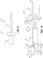
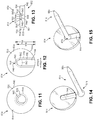
- FIGS. 5 and 6 illustrate another medical device 410.
- the medical device 410 is similar to the medical device 10 illustrated in FIGS. 1, 2 , and 3 and described above, except as detailed below.
- the medical device 410 comprises an elongate member 412, an intermediate member 414, and a tubular member 416.
- the elongate member 412 has a body 428 that defines a proximal portion 430 and a shaft 432 that extends distally from the distal end 436 of the proximal portion 430.
- the proximal portion 430 has an outside diameter 437 that is constant along the length 435 of the proximal portion 430.
- the outside diameter 437 of the proximal portion 430 is greater than the first outside diameter 447 of the shaft 432.
- the intermediate member 414 omits the inclusion of a protuberance (e.g., protuberance 68) and the body 456 of the intermediate member 414 defines a first support post 470 and a second support post 474.
- the first surface 464 is disposed on the proximal end 452 of the intermediate member 414 and the second surface 466 is disposed on the distal end 454 of the intermediate member 414.
- the first support post 470 extends from the second surface 466 and away from the first surface 464 to a first support post end 472 and the second support post 474 extends from the second surface 466 and away from the first surface 464 to a second support post end 475.
- Each of the first support post 470 and second support post 474 is cuboidal.
- the first support post 470 has a length that is equal to the length of the second support post 474.
- the first support post 470 has a first lengthwise axis that extends through its length that is parallel to a second lengthwise axis that extends through the length of the second support post 474.
- first lengthwise axis is substantially parallel, or not parallel, to the second lengthwise axis.
- first support post 470 has been illustrated as having a length that is equal to the length of the second support post 474, a support post can have any suitable length. Skilled artisans will be able to select a suitable length for a support post according to a particular embodiment based on various considerations, including the structural arrangement of a tubular member included in a medical device of which the intermediate member is a component. Example lengths considered suitable for a support post include a first support post that has a length that is greater than, equal to, substantially equal to, or less than the length of a second support post.
- the tubular member 416 omits the inclusion of a flared proximal portion (e.g., flared proximal portion 88) and has a body 480 that defines a first opening 482, a second opening 484, a lumen 486, a tapered distal portion 490, a first passageway 492, a second passageway 504, a first surface 506, and a second surface 508.
- the first opening 482 is defined on the proximal end 476 and the second opening 484 is defined on the distal end 478.
- the lumen 486 extends from the first opening 482 to the second opening 484.
- Each of the first opening 482, second opening 484, and lumen 486 has an inside diameter 479 that is greater than the first outside diameter 447 of the shaft 432.
- the first surface 506 is opposably facing the second surface 508.
- the first surface of a tubular member can be substantially opposably facing the second surface, or disposed at an angle to the second surface.
- the tubular member 416 has a first outside diameter 487, a second outside diameter 489, and a third outside diameter 491.
- the first outside diameter 487 is greater than the second outside diameter 489 and the second outside diameter 489 is greater than the third outside diameter 491.
- the first outside diameter 487 extends from the first surface 506 to the second surface 508.
- the first outside diameter 487 extends along a first portion 496 of the tubular member 416 that extends from the proximal end 476 to the second surface 508.
- the second outside diameter 489 extends along a second portion 500 of the tubular member 416 that extends from the first portion 496 (e.g., the second surface 508) toward the distal end 478.
- the second outside diameter 489 tapers to the third outside diameter 491 along a third portion 502 of the tubular member 416 that extends from the second portion 500 to the distal end 478 of the tubular member 416.
- This structural arrangement of the tubular member 416 defines a shoulder 509 between the proximal end 476 and the distal end 478 of the tubular member 416.
- the shoulder 509 acts as a mechanical stop to distal advancement of the tubular member 416 beyond the tissue disposed outside of the bodily passage (e.g., the second surface 508 contacts the tissue disposed outside of the bodily passage).
- the first passageway 492 extends from an opening defined on the first surface 506 to an opening defined on the second surface 508.
- the second passageway 504 extends from an opening defined on the first surface 506 to an opening defined on the second surface 508.
- the first passageway 492 has an inside diameter that is greater than the outside diameter of the first support post 470 and second passageway 504 has an inside diameter that is greater than the outside diameter of the second support post 474.
- the first passageway and/or second passageway defined by a tubular member can have an inside diameter that is equal to, substantially equal to, or less than the outside diameter of a support post such that a friction fit between the intermediate member and tubular member can be accomplished.
- the first passageway 492 has a structural arrangement that is complementary to the first support post 470 and the second passageway 504 has a structural arrangement that is complementary to the second support post 474.
- each of the first passageway 492 and second passageway 504 is cuboidal.
- the first passageway 492 has a first lengthwise axis and the second passageway 504 has a second lengthwise axis.
- the first lengthwise axis is parallel to the second lengthwise axis.
- other structural arrangements are considered suitable, such as structural arrangements in which the first lengthwise axis is substantially parallel, or not parallel, to the second lengthwise axis.
- intermediate member 414 When the medical device 410 is fully assembled, intermediate member 414 is releasably disposed on shaft 432 between the distal end 436 of the proximal portion 430 and the proximal end 476 of tubular member 416. Thus, intermediate member 414 is disposed between the proximal portion 430 and the tubular member 416.
- the tubular member 416 is releasably disposed on shaft 432 and is disposed distal to intermediate member 414 such that the first support post 470 is disposed through the first passageway 492 and the second support post 474 is disposed through the second passageway 504.
- the lengthwise axis of the first support post 470 is coaxial with the lengthwise axis of the first passageway 492 and the lengthwise axis of the second support post 474 is coaxial with the lengthwise axis of the second passageway 504.
- the lengthwise axis of the support post of an intermediate member can be disposed at an angle to the lengthwise axis of a passageway defined by a tubular member.
- FIG. 7 is a flowchart representation of a method 600 of treating a bodily passage.
- a step 602 comprises introducing a medical device having a medical device proximal end and a medical device distal end into a bodily passage such that the medical device distal end is disposed within the bodily passage.
- the bodily passage is defined by a bodily passage wall.
- Another step 604 comprises advancing the medical device into the bodily passage until the second outside diameter of the tubular member is disposed within the bodily passage.
- Another step 606 comprises applying a distally-directed force on the intermediate member.
- Another step 608 comprises applying a proximally-directed force on the elongate member while applying a distally-directed force on the intermediate member such that the elongate member is advanced proximally relative to the intermediate member and the tubular member.
- Another step 610 comprises continuing the application of a proximally-directed force on the elongate member while applying a distally-directed force on the intermediate member until the elongate member is free of the intermediate member and the tubular member.
- Another step 612 comprises separating the intermediate member from the tubular member.
- Another step 614 comprises withdrawing the tubular member from the bodily passage.
- Step 602 can be accomplished using any suitable medical device according to an embodiment, such as the embodiments described and illustrated herein. Skilled artisans will be able to select a suitable medical device to introduce into a bodily passage according to a particular embodiment based on various considerations, including the treatment intended to be performed. Examples of medical devices considered suitable to introduce into a bodily passage to complete one or more steps and/or methods described herein include medical device 10, medical device 210, medical device 410, medical device 810, medical devices that include the alternative components described herein (e.g., elongate member 12', intermediate member 14', intermediate member 814', tubular member 1016), and any other medical device considered suitable for a particular application.
- Step 602 can be accomplished by introducing a medical device into any suitable bodily passage.
- Skilled artisans will be able to select a suitable bodily passage to introduce a medical device according to a particular embodiment based on various considerations, including the treatment intended to be performed.
- Example bodily passages considered suitable to introduce a medical device include a salivary duct, a portion of the urinary tract, and any other bodily passage considered suitable for a particular application.
- Step 604 can be accomplished by applying a distally-directed force (e.g., toward the bodily passage) on any suitable portion of the medical device such that the medical device is advanced into the bodily passage and the second outside diameter of the tubular member is disposed within the bodily passage.
- a distally-directed force can be applied to an elongate member of an embodiment, such as elongate member 12, elongate member 12', elongate member 212, elongate member 412, or elongate member 812.
- An optional step comprises advancing the medical device into the bodily passage such that the flared proximal portion of the tubular member contacts tissue disposed outside of the bodily passage. This step can be accomplished by placing a distally-directed force on any suitable portion of the medical device until the distal surface of the flared proximal portion contacts the tissue disposed outside of the bodily passage.
- an optional step comprises advancing the medical device into the bodily passage such that the second surface of the tubular member contacts tissue disposed outside of the bodily passage.
- This step can be accomplished by placing a distally-directed force on any suitable portion of the medical device until the distal surface of second surface of the tubular member contacts the tissue disposed outside of the bodily passage.
- an optional step comprises advancing the medical device into the bodily passage such that the proximal end of the tubular member is disposed adjacent, or near, an opening of the bodily passage.
- This step can be accomplished by placing a distally-directed force on any suitable portion of the medical device until the distal surface of second surface of the tubular member contacts the tissue disposed outside of the bodily passage.
- Step 606 can be accomplished by applying a distally-directed force on the intermediate member such that the intermediate member is advanced toward and/or contacts the tissue disposed outside of the bodily passage.
- the distally-directed force can be applied to any suitable portion of an intermediate member, such as the outside perimeter, or edge, of the intermediate member, and/or the first surface of an intermediate member (e.g., first surface 64, first surface 264, first surface 464, first surface 864).
- an alternative step comprises maintaining the position of the intermediate member relative to the tubular member. This step can be accomplished by applying any suitable force on the intermediate member such that the position of the intermediate member is maintained relative to the tubular member, the tissue disposed outside of the bodily passage, and/or the bodily passage.
- Step 608 can be accomplished by applying a proximally-directed force (e.g., away from the bodily passage) on any suitable portion of the elongate member while applying a distally-directed force on the intermediate member such that the elongate member is advanced proximally relative to the intermediate member and tubular member and is advanced proximally through the lumen defined by the tubular member.
- a proximally-directed force e.g., away from the bodily passage
- a distally-directed force e.g., away from the bodily passage
- step 608 can be accomplished concurrently with step 606.
- Proximally-directed force can be applied to proximal portion 30, proximal portion 30', proximal portion 230, proximal portion 430, proximal portion 830, or any other portion of an elongate member considered suitable for a particular application.
- an alternative step comprises applying a proximally-directed force on the elongate member while maintaining the position of the intermediate member relative to the tubular member such that the elongate member is advanced proximally relative to the intermediate member and the tubular member and is advanced proximally through the lumen defined by the tubular member.
- Step 610 can be accomplished by continuing the application of a proximally-directed force on the elongate member while applying a distally-directed force on the intermediate member until the distal end of the shaft is disposed proximal to the proximal end of the intermediate member and the elongate member is free of the tubular member and the intermediate member.
- an alternative step comprises continuing the application of a proximally-directed force on the elongate member while maintaining the position of the intermediate member relative to the tubular member until the distal end of the shaft is disposed proximal to the proximal end of the intermediate member and the elongate member is free of the intermediate member and the tubular member.
- Step 612 can be accomplished by applying a proximally-directed force (e.g., away from the bodily passage) on any suitable portion of the intermediate member (e.g., disc-shaped portion 67, cuboid portion 267, disc-shaped portion 467) such that the support post is withdrawn from the passageway defined by the tubular member.
- a proximally-directed force e.g., away from the bodily passage
- the intermediate member includes more than one support post and the tubular member defines more than one passageway (e.g., intermediate member 414, tubular member 416)
- this step can be accomplished by applying a proximally-directed force on any suitable portion of the intermediate member such that each of the support posts is withdrawn from its respective passageway.
- this step can be accomplished by applying a proximally-directed force on any suitable portion of the intermediate member such that is free of contact with the tubular member.
- this step can be accomplished by applying a transverse force on the intermediate member relative to the lengthwise axis of the tubular member, a transverse force on the tubular member relative to the lengthwise axis of the intermediate member, or by applying a transverse force on both the intermediate member and the tubular member relative to the lengthwise axis of the tubular member such that the intermediate member is separated from the tubular member.
- Step 614 can be accomplished by applying a proximally-directed force (e.g., away from the bodily passage) on the tubular member until it has been withdrawn from the bodily passage such that the distal end of the tubular member is disposed proximal to the bodily passage.
- a proximally-directed force e.g., away from the bodily passage
- step 614 can be omitted from method 600.
- step 614 can be omitted in embodiments in which the tubular member is formed of a biodegradable or bioabsorbable material.
- An optional step that can be completed prior to withdrawing the tubular member from the bodily passage comprises suturing the tubular member to tissue that is disposed outside of the bodily passage. This step can be accomplished by passing a suture through a passageway defined by the tubular member and through the tissue that is disposed outside of the bodily passage to secure the tubular member to the tissue and within the bodily passage.
- an optional step than can be completed prior to withdrawing the tubular member from the bodily passage comprises passing a suture through each passageway, or one or more of the passageways, and through the tissue that is disposed outside of the bodily passage to secure the tubular member to the wall that defines the bodily passage.
- a step that can be completed in addition to, or alternative to, the optional steps described above and prior to withdrawing the tubular member from the bodily passage comprises suturing the tubular member to the wall that defines the bodily passage.
- This step can be accomplished by passing a suture through a passageway defined by the tubular member and through the bodily passage wall to secure the tubular member to the bodily passage wall and within the bodily passage.
- this step comprises passing a suture through each passageway, or one or more of the passageways, and through the bodily passage wall to secure the tubular member to the bodily passage wall.
- An optional step that can be completed prior to withdrawing the tubular member from the bodily passage comprises leaving the tubular member in the bodily passage for an interval of time.
- Any suitable interval of time is considered suitable, and skilled artisans will be able to select a suitable interval of time to leave a tubular member in a bodily passage according to a particular embodiment based on various considerations, including the treatment intended to be performed.
- Example intervals of time considered suitable to leave a tubular member within a bodily passage include one or more minutes, one or more hours, one or more days, and any other interval of time considered suitable for a particular application.
- Another optional step that can be completed prior to withdrawing the tubular member from the bodily passage comprises passing a medication and/or medical device through the lumen defined by the tubular member and into the bodily passage to perform treatment.
- a medical device can be passed through a portion of the lumen defined by the tubular member. This step can be accomplished using any suitable medication and/or medical device, and skilled artisans will be able to select a suitable medication and/or medical device to pass through the entirety, or a portion, of a tubular member according to a particular embodiment based on various considerations, including the treatment intended to be performed.
- Example medical devices considered suitable to pass through the lumen defined by a tubular member include suction catheters, balloon catheters, irrigation catheters, a camera, a light source, and any other medical device considered suitable for a particular application.
- Another optional step comprises performing treatment with a medical device that has been passed through a portion, or the entirety, of the lumen defined by the tubular member.
- Another optional step comprises withdrawing the medical device from the lumen defined by the tubular member.
- FIG. 8 is a flowchart representation of another method 700 of treating a bodily passage.
- a step 702 comprises introducing a guide wire having a guide wire proximal end and a guide wire distal end into a bodily passage such that the guide wire distal end is disposed within the bodily passage.
- the bodily passage is defined by a bodily passage wall.
- Another step 704 comprises advancing a medical device having a medical device proximal end and a medical device distal end over the guide wire such that the guide wire is disposed within a lumen defined by an elongate member of the medical device.
- Another step 706 comprises introducing the medical device into the bodily passage such that the medical device distal end is disposed within the bodily passage.
- Another step 708 comprises advancing the medical device into the bodily passage until the second outside diameter of the tubular member is disposed within the bodily passage.
- Another step 710 comprises withdrawing the guide wire from the bodily passage and the medical device.
- Another step 712 comprises maintaining the position of the intermediate member relative to the tubular member.
- Another step 714 comprises applying a proximally-directed force on the elongate member while maintaining the position of the intermediate member such that the elongate member is advanced proximally relative to the intermediate member and the tubular member.
- Another step 716 comprises continuing the application of a proximally-directed force on the elongate member while maintaining the position of the intermediate member until the elongate member is free of the intermediate member and the tubular member.
- Another step 718 comprises separating the intermediate member from the tubular member.
- Another step 720 comprises suturing the tubular member to tissue.
- Another step 722 comprises allowing an interval of time to pass.
- Another step 724 comprises removing the sutures from the tissue and the tubular member.
- Another step 726 comprises withdrawing the tubular member from the bodily passage.
- Step 702 can be accomplished using any suitable guide wire having any suitable length and structural arrangement. Skilled artisans will be able to select a guide wire to introduce into a bodily passage according to a particular embodiment based on various considerations, including the treatment intended to be performed. Step 702 can be accomplished by applying a distally-directed force (e.g., toward the bodily passage) on any suitable portion of the guide wire such that the guide wire distal end is advanced into the bodily passage.
- a distally-directed force e.g., toward the bodily passage
- Step 702 can be accomplished by introducing a guide wire into any suitable bodily passage.
- Skilled artisans will be able to select a suitable bodily passage to introduce a guide wire according to a particular embodiment based on various considerations, including the treatment intended to be performed.
- Example bodily passages considered suitable to introduce a guide wire include a salivary duct, a portion of the urinary tract, and any other bodily passage considered suitable for a particular application.
- Step 704 can be accomplished using any suitable medical device according to an embodiment, such as the embodiments described and illustrated herein. Skilled artisans will be able to select a suitable medical device to advance over a guide wire according to a particular embodiment based on various considerations, including the treatment intended to be performed. Examples of medical devices considered suitable to advance over a guide wire to complete one or more steps and/or methods described herein include medical devices that include an elongate member that defines a lumen that extends from the proximal end of the elongate member to the distal end of the elongate member (e.g., elongate member 212).
- an elongate member that defines a lumen that extends from the proximal end of the elongate member to the distal end of the elongate member (e.g., elongate member 212).
- any of the medical devices described and illustrated herein such as medical device 10, medical device 210, medical device 410, medical device 810, medical devices that include the alternative components described herein (e.g., elongate member 12', intermediate member 14', intermediate member 814', tubular member 1016), are considered suitable and can include an elongate member that defines a lumen that extends from the proximal end of the elongate member to the distal end of the elongate member.
- Step 704 can be accomplished by passing the proximal end of the guide wire through a distal opening of the lumen defined by the elongate member (e.g., lumen 324 of elongate member 212) and applying a distally-directed force (e.g., toward the bodily passage) on any suitable portion of the medical device such that the guide wire is passed through the a proximal opening of the lumen and the medical device is disposed on the guide wire.
- a distally-directed force e.g., toward the bodily passage
- Step 706 can be accomplished as described above with respect to step 602 and by applying a distally-directed force (e.g., toward the bodily passage) on any suitable portion of the medical device such that the medical device distal end is advanced distally over the guide wire and introduced into the bodily passage.
- a distally-directed force e.g., toward the bodily passage
- Step 708 can be accomplished by applying a distally-directed force (e.g., toward the bodily passage) on any suitable portion of the medical device such that the medical device distal end is advanced into the bodily passage, over the guide wire, and the second outside diameter of the tubular member is disposed within the bodily passage.
- a distally-directed force can be applied to an elongate member of an embodiment, such as elongate member 12, elongate member 12', elongate member 212, elongate member 412, or elongate member 812.
- An optional step comprises advancing the medical device into the bodily passage such that the flared proximal portion of the tubular member contacts tissue disposed outside of the bodily passage. This step can be accomplished by placing a distally-directed force on any suitable portion of the medical device until the distal surface of the flared proximal portion contacts the tissue disposed outside of the bodily passage.
- an optional step comprises advancing the medical device into the bodily passage such that the second surface of the tubular member contacts tissue disposed outside of the bodily passage.
- This step can be accomplished by placing a distally-directed force on any suitable portion of the medical device until the second surface of the tubular member contacts the tissue disposed outside of the bodily passage.
- an optional step comprises advancing the medical device into the bodily passage such that the proximal end of the tubular member is disposed adjacent, or near, an opening of the bodily passage.
- This step can be accomplished by placing a distally-directed force on any suitable portion of the medical device until the distal surface of second surface of the tubular member contacts the tissue disposed outside of the bodily passage.
- Step 710 can be accomplished by applying a proximally-directed force (e.g., away from the bodily passage) on any suitable portion of the guide wire such that the guide wire is withdrawn from the bodily passage and the lumen defined by the elongate member.
- a proximally-directed force e.g., away from the bodily passage
- this step can be completed prior to step 720 or step 722.
- Step 712 can be accomplished by maintaining the position of the intermediate member relative to the tubular member. This step can be accomplished by applying any suitable force (e.g., distally-directed, proximally-directed, radially-directed) on the intermediate member such that the position of the intermediate member is maintained relative to the tubular member, the tissue disposed outside of the bodily passage, and/or the bodily passage.
- any suitable force e.g., distally-directed, proximally-directed, radially-directed
- Step 714 can be accomplished by applying a proximally-directed force (e.g., away from the bodily passage) on any suitable portion of the elongate member while maintaining the position of the intermediate member relative to the tubular member such that the elongate member is advanced proximally relative to the intermediate member and tubular member and the elongate member is advanced proximally through the lumen defined by the tubular member.
- a proximally-directed force e.g., away from the bodily passage
- step 714 can be accomplished concurrently with step 712.
- Proximally-directed force can be applied to the proximal portion 30, proximal portion 30', proximal portion 230, proximal portion 430, proximal portion 830, or any other portion of an elongate member considered suitable for a particular application.
- Step 716 can be accomplished by continuing the application of a proximally-directed force (e.g., away from the bodily passage) on the elongate member while maintaining the position of the intermediate member relative to the tubular member until the distal end of the shaft is disposed proximal to the proximal end of the intermediate member and the elongate member is free of the intermediate member and the tubular member.
- a proximally-directed force e.g., away from the bodily passage
- Step 718 can be accomplished by applying a proximally-directed force (e.g., away from the bodily passage) on any suitable portion of the intermediate member (e.g., disc-shaped portion 67, cuboid portion 267, disc-shaped portion 467) such that the support post is withdrawn from the passageway defined by the tubular member.
- the intermediate member includes more than one support post and the tubular member defines more than one passageway (e.g., intermediate member 414, tubular member 416)
- this step can be accomplished by applying a proximally-directed force (e.g., away from the bodily passage) on any suitable portion of the intermediate member such that each of the support posts is withdrawn from its respective passageway.
- this step can be accomplished by applying a transverse force on the intermediate member relative to the lengthwise axis of the tubular member, a transverse force on the tubular member relative to the lengthwise axis of the intermediate member, or by applying a transverse force on both the intermediate member and the tubular member relative to the lengthwise axis of the tubular member such that the intermediate member is separated from the tubular member.
- Step 720 can be accomplished by suturing the tubular member to tissue that is disposed outside of the bodily passage. This step can be accomplished by passing one or more sutures through a passageway defined by the tubular member and through the tissue that is disposed outside of the bodily passage to secure the tubular member to the tissue and within the bodily passage.
- an alternative step than can be completed prior to withdrawing the tubular member from the bodily passage comprises passing one or more sutures through each passageway, or one or more of the passageways, and through the tissue that is disposed outside of the bodily passage to secure the tubular member to the wall that defines the bodily passage.
- step 720 comprises suturing the tubular member to tissue that defines the bodily passage.
- This step can be accomplished by passing one or more sutures through a passageway defined by the tubular member and through the tissue that defines the bodily passage to secure the tubular member to the tissue and within the bodily passage.
- this step comprises passing one or more sutures through each passageway, or one or more of the passageways, and through the tissue that defines the bodily passage to secure the tubular member to the wall that defines the bodily passage.
- Step 722 can be accomplished by allowing an interval of time to pass before removing the sutures and withdrawing the tubular member from the bodily passage. Any suitable interval of time is considered suitable, and skilled artisans will be able to select a suitable interval of time to leave a tubular member in a bodily passage according to a particular embodiment based on various considerations, including the treatment intended to be performed.
- Example intervals of time considered suitable to leave a tubular member within a bodily passage include one or more minutes, one or more hours, one or more days, and any other interval of time considered suitable for a particular application.
- Step 724 can be accomplished by removing the one or more sutures such that the tubular member can be removed from the bodily passage.
- step 724 can be omitted from method 700.
- step 724 can be omitted in embodiments in which the one or more sutures are formed of a biodegradable or bioabsorbable material.
- Step 726 can be accomplished by applying a proximally-directed force (e.g., away from the bodily passage) on the tubular member until it has been withdrawn from the bodily passage such that the distal end of the tubular member is disposed proximal to the bodily passage.
- a proximally-directed force e.g., away from the bodily passage
- step 726 can be omitted from method 700.
- step 726 can be omitted in embodiments in which the tubular member is formed of a biodegradable or bioabsorbable material.
- steps, alternative steps, and optional steps have been described above with respect to treating a bodily passage, these steps, alternative steps, and optional steps can be included in, accomplished concurrently with, and/or accomplished in the alternative to, the methods, steps, alternative steps, and/or optional steps described above with respect to method of treatment 600.
- FIGS. 9, 10 , 11, 12, 13, 14, and 15 illustrate another medical device 810.
- Medical device 810 is similar to the medical device 10 illustrated in FIGS. 1, 2 , and 3 and described above, except as detailed below.
- the medical device 810 comprises an elongate member 812, an intermediate member 814, and a tubular member 816.
- the proximal portion 830 has a first outside diameter 837 and a second outside diameter 839 and the body 828 of the elongate member 812 defines a protuberance 930.
- the first outside diameter 837 of the proximal portion 830 is disposed on the distal end 836 of the proximal portion 830 and the second outside diameter 839 of the proximal portion 830 is disposed on the proximal end 834 of the proximal portion 830.
- the first outside diameter 837 is greater than the second outside diameter 839.
- the body 828 of the elongate member 812 defines the first outside diameter 837 along a first portion 838 of the proximal portion 830 and the second outside diameter 839 along a second portion 840 of the proximal portion 830.
- the first portion 838 extends from the distal end 836 toward the proximal end 834 to the second portion 840 and has a length that is less than the length 835 of the proximal portion 830.
- the second portion 840 extends from the first portion 838 to the proximal end 834 of the proximal portion 830 and has a length that is greater than the length 835 of the proximal portion 830.
- other structural arrangements are considered suitable, such as a first portion that has a length that is greater than, equal to, or substantially equal to, the length of a second portion.
- the protuberance 930 is defined between the proximal end 844 of the shaft 832 and the distal end 846 of the shaft 832.
- the protuberance 930 extends outward and away from the shaft 832 and has an outside diameter 931 and a thickness 932.
- the outside diameter 931 of the protuberance 930 is greater than the first outside diameter 847 of the shaft 832 that extends from the protuberance 930 toward the distal end 846 of the shaft 832.
- the thickness 932 of the protuberance 930 extends from the proximal end of the protuberance 930 to the distal end of the protuberance 930 and can be any suitable thickness capable of releasably attaching the intermediate member 814 to the elongate member 812, as described in more detail herein.
- the portion of the shaft 832 disposed between the proximal portion 830 and the protuberance 930 has an outside diameter that is less than the outside diameter 931 of the protuberance 930. In the illustrated embodiment, the portion of the shaft 832 disposed between the proximal portion 830 and the protuberance 930 has an outside diameter that is greater than the first outside diameter 847 of the shaft 832 disposed distal to the protuberance 930.
- alternative embodiments can include a portion of the shaft that is disposed between the proximal portion 830 and the protuberance 930 that has an outside diameter that is equal to, substantially equal to, or less than the first outside diameter 847 of the shaft 832 that is distal to the protuberance 930.
- the protuberance 930 is described as defined by the body 828 of the elongate member 812, a protuberance can alternatively be a separate component attached to the shaft of an elongate member using any suitable technique or method of attachment, such as welding, or by using adhesives.
- the body 856 of the intermediate member 814 defines a first opening 858, a second opening 860, a lumen 862, an edge 940, a notch 942, a slot 944, and recess 946.
- the first opening 858 is disposed on the proximal end 852 and the second opening 860 is defined within the slot 944 (e.g., between the first surface 864 and the second surface 866) such that the second opening 860 is in communication with slot 944.
- the lumen 862 extends from the first opening 858 to the second opening 860 thereby extending from the proximal end 852 of the intermediate member 814 to the slot 944.
- the edge 940 of the intermediate member 814 extends from the first surface 864 to the second surface 866.
- the notch 942 is defined on the edge 940, interrupts the surface of the edge 940, and is sized and configured to receive a portion of the tubular member 816.
- the notch 942 is in communication with the first opening 858, second opening 860, and the lumen 862 via slot 944, as described in more detail herein.
- the slot 944 is cooperatively defined by the edge 940 and the second surface 866 and extends from the second surface 866 into the intermediate member body 856.
- the slot 944 extends from the notch 942 defined on the edge 940 to a slot end 948 and from the second surface 866 and into the body 856 of the intermediate member 814.
- the second opening 860 is disposed between the notch 942 and the slot end 948 such that the slot 944 is in communication with the lumen 862 defined by the intermediate member 814.
- the slot 944 has a first portion 950 and a second portion 952 and is sized and configured to receive a portion of the tubular member 816 (e.g., flared proximal portion 888).
- a slot can be sized and configured to receive any suitable tubular member, or portion of a tubular member, such as tubular member 16, tubular member 216, tubular member 416, tubular member 1016, and any other tubular member considered suitable to include in a medical device.
- the first portion 950 has a first width 954, a first depth 956, a first height 958, and an end 960.
- the first width 954 is defined on the second surface 866 and is less than the first outside diameter 887 of the tubular member 816, greater than the second outside diameter 889 of the tubular member 816, and less than the diameter of the second opening 860.
- alternative embodiments can include a first portion that has a width that is greater than the diameter of the second opening and/or less than the second outside diameter of the tubular member such that an interference fit between the intermediate member and the tubular member can be achieved.
- the first depth 956 extends from the second surface 866 and into the body 856 of the intermediate member 814 toward the first surface 864 and is less than the second depth 964, as described herein.
- alternative embodiments can include a slot that has a first depth that is greater than, equal to, or substantially equal to, the second depth.
- the first height 958 extends from the edge 940 to the end 960 of the first portion 950 along a portion of the diameter of the intermediate member 814.
- the second portion 952 has a second width 962, a second depth 964, a second height 966, and an end 968.
- the second width 962 is greater than the first width 954 and is disposed between the proximal end 852 and the distal end 854 of the intermediate member 814.
- the slot 944 defines a shoulder 970 between the proximal end 852 and the distal end 854 of the intermediate member 814.
- the second width 962 is greater than the first outside diameter 887 of the tubular member 816.
- alternative embodiments can include a second inside diameter that is less than, equal to, or substantially equal to, the first outside diameter of a tubular member.
- the second depth 964 extends from the first portion 950 of the slot 944 into the body 856 of the intermediate member 814 and away from the second surface 866 (e.g., toward the first surface 864).
- the second depth 964 is sized and configured to receive the third portion 896 (e.g., flared proximal portion 888) of the tubular member 816 such that the tubular member 816 can be releasably attached within the slot 944.
- the second depth 964 has a length that is equal to the length of the third portion 896 (e.g., flared proximal portion 888) of the tubular member 816.
- alternative embodiments can include a second depth has a length that is substantially equal to, greater than, or less than, the length of the third portion of the tubular member.
- the second height 966 extends from the edge 940 to the end 968 of the second portion 952 and is greater than the first height 958.
- the end 960 of the first portion 950 is disposed a first distance from the center of the intermediate member 814 and the end 968 of the second portion 952 is disposed a second distance from the center of the intermediate member 814. The second distance is greater than the first distance.
- the end 968 of the second portion 952 is positioned such that when the tubular member 816 is disposed within the slot 944, as shown in FIG.
- the lumen 862 defined by the intermediate member 814 is aligned with the lumen 886 defined by the tubular member 816 such that they are coaxial and/or in communication with one another.
- the end 960 of the first portion 950 is configured such that it corresponds to the structural arrangement of the exterior surface of the tubular member 816 along the fourth portion 900.
- the end 968 of the second portion 952 is configured such that it corresponds to the structure of the proximal end 876 of the tubular member 816.
- the end 960 of the first portion 950 and the end 968 of the second portion 952 are curved.
- alternative embodiments can include an intermediate member that defines a slot that has any suitable configuration, such as those that correspond to the configuration of the proximal end of a tubular member.
- the end of the first portion and/or second portion of a slot can be configured such that they do not correspond to the structure of a tubular member.
- the recess 946 is defined between the proximal end (e.g., first opening 858) and the distal end of the lumen 862 (e.g., second opening 860) within the lumen 862 and has an inside diameter that is greater than the inside diameter of the lumen 862.
- the recess 946 extends along a first portion 855 of the intermediate member 814 and is sized and configured to receive the protuberance 930.
- the diameter of the recess 946 is equal to the outside diameter 931 of the protuberance 930 and the first portion 855 of the intermediate member 814 has a length that is equal to the thickness 932 of the protuberance 930.
- This configuration provides a snap fit configuration between the elongate member 812 and the intermediate member 814 when the two components are releasably attached to one another.
- alternative embodiments could include a recess that has a diameter that is greater than, substantially equal to, or less than the outside diameter of a protuberance and/or a recess that extends along a portion of the intermediate member that is greater than, substantially equal to, or less than the thickness of the protuberance.
- the shaft 832 of the elongate member 812 is passed through lumen 862 such that the protuberance 930 is partially disposed within the recess 946.
- alternative embodiments can include a protuberance that is entirely disposed within a recess defined by an intermediate member when the two components are releasably attached to one another.
- the intermediate member 814 is formed of a material that is relatively more flexible than the material that forms elongate member 812 such that first opening 858 can expand when protuberance 930 is advanced distally through the lumen 862 and return to its original configuration, or a configuration that is substantially similar to its original configuration, after the protuberance 930 is disposed within the recess 946.
- a portion (e.g., protuberance), or the entirety, of the shaft can be formed of a material that is relatively more flexible than the material that forms the intermediate member such that the protuberance can compress and allow the intermediate member to be passed over the protuberance until the protuberance is disposed within the recess defined by the intermediate member.
- any suitable locking structure can be included on an elongate member and/or an intermediate member to provide releasable attachment between the elongate member and the intermediate member.
- Skilled artisans will be able to select a suitable locking structure to include on an elongate member and/or intermediate member according to a particular embodiment based on various considerations, including the material(s) that forms the elongate member and the intermediate member.
- Example locking structures considered suitable include interlocking structures, structures that provide a friction fit between the elongate member and the intermediate member (e.g., the shaft of the elongate member has an outside diameter that is greater than a portion of the intermediate member lumen such that a friction fit can be achieved), mechanical fasteners, morse taper configurations, and any other structure considered suitable for a particular embodiment.
- a slot defined by an intermediate member can have any suitable structural arrangement capable of releasably attaching a tubular member to the intermediate member.
- Skilled artisans will be able to select a suitable structural arrangement for a slot according to a particular embodiment based on various considerations, including the structural arrangement of the proximal end of a tubular member and/or the material(s) that forms a tubular member.
- a slot can be tapered such that it corresponds to the structural arrangement of an embodiment of the proximal end of a tubular member.
- intermediate member 814' similar to intermediate member 814 except intermediate member 814' defines a slot 944' that has a tapered configuration that corresponds with the structural arrangement of an embodiment of a tubular member (e.g., tubular member 16, tubular member 216, tubular member 816).
- a slot can extend from an opening defined on a surface of an intermediate member (e.g., second surface of an intermediate member) to a slot end.
- the proximal end of the tubular member can be advanced through the opening defined on the surface of the intermediate member and toward the slot end to align the lumen defined by the tubular member with the lumen defined by the intermediate member such that they are coaxial an/or in communication with one another.
- the first opening 882 of the tubular member 816 has a diameter that is equal to the diameter of the lumen 862 defined by the intermediate member 814.
- the first opening of a tubular member can have any suitable diameter, such as a diameter that is greater than, less than, or equal to, the diameter of the lumen defined by an intermediate member.
- the intermediate member 814 and the tubular member 816 have a first configuration and a second configuration.
- the tubular member 816 is free of the intermediate member 814, as shown in FIG. 14 .
- the tubular member 816 is partially disposed within the slot 944 defined by the intermediate member 814 such that the tubular member 816 is releasably attached to the intermediate member 814, as shown in FIGS. 9 and 15 .
- the proximal end 876 of the tubular member 816 is positioned near the notch 942 defined on the edge 940 of the intermediate member 814, as shown in FIG. 14 , and is advanced into slot 944, as shown in FIG. 15 .
- the tubular member 816 is advanced into the slot 944 by applying a transverse force on the intermediate member 814 relative to the lengthwise axis of the tubular member 816, a transverse force on the tubular member 816 relative to the lengthwise axis of the intermediate member 814, or by applying a transverse force on both the intermediate member 814 and the tubular member 816 relative to the lengthwise axis of the tubular member 816.
- the transverse force(s) is applied until the lumen 862 defined by the intermediate member 814 is in communication with the lumen 886 defined by the tubular member 816 (e.g., lumen 862 defined by the intermediate member 814 is aligned, or coaxial, with the lumen 886 defined by the tubular member 816).
- the tubular member 816 when assembled, the tubular member 816 is partially disposed within the slot 944 defined by the intermediate member 814. Subsequently, the distal end 826 of the elongate member 812 is advanced through the lumen 862 defined by the intermediate member 814 and the lumen 886 defined by the tubular member 816 until the protuberance 930 is disposed within the recess 946 defined by the intermediate member 814 and the distal end 836 of the proximal portion 830 contacts the first surface 864 of the intermediate member 814.
- the intermediate member 814 is releasably attached to the tubular member 812 and is disposed on the shaft 832 such that a portion of the intermediate member 814 is disposed between the distal end 836 of the proximal portion 830 and the proximal end 876 of tubular member 816. Thus, a portion of the intermediate member 814 is disposed between the proximal portion 830 and the tubular member 816.
- FIGS. 16, 17, and 18 illustrate an alternative tubular member 1016.
- Tubular member 1016 is similar to the tubular member 16 illustrated in FIGS. 1, 2 , and 3 and described above, except as detailed below.
- the tubular member 1016 comprises a proximal end 1076, a distal end 1078, and a body 1080.
- the body 1080 of the tubular member 1016 defines a first set of passageways 1092 on the flared proximal portion 1088 and a second set of passageways 1093 on the fourth portion 1100 of the tubular member 1016.
- Each passageway in the first set of passageways 1092 is defined on an axis that is disposed parallel to the lengthwise axis of the tubular member 1016 and provides access to the lumen 1086 defined by the tubular member 1016.
- alternative embodiments can include one or more passageways defined on the flared proximal portion 1088 that are disposed on an axis that is not parallel to the lengthwise axis of the tubular member 1016.
- a first portion of the second set of passageways 1093 is disposed on a first side of the fourth portion 1100 of the tubular member 1016 and a second portion of the second set of passageways 1093 is disposed on a second side of the fourth portion 1100 of the tubular member 1016.
- the first portion of the second set of passageways 1093 is opposably positioned from the second portion of the second set of passageways 1093 relative to the lengthwise axis of the tubular member 1016.
- alternative embodiments can include a first portion of a set of passageways that are positioned at any suitable location on a tubular member relative to a second portion of the set of passageways (e.g., first portion is not opposably positioned from the second portion).
- Each passageway in the second set of passageways 1093 is defined on an axis that is disposed orthogonal to the lengthwise axis of the tubular member 1016 and provides access to the lumen 1086 defined by the tubular member 1016.
- alternative embodiments can include one or more passageways defined on the fourth portion 1100 of the tubular member 1016 that are disposed on an axis that is not orthogonal to the lengthwise axis of the tubular member 1016.
- Each passageway of the first set of passageways 1092 and second set of passageways 1093 has a diameter that is sized and configured to receive a thread, the same thread a plurality of times, or a plurality of threads, such that the tubular member 1016 can be sutured to the tissue disposed outside of the bodily passage and/or the bodily passage wall.
- each passageway of the first set of passageways 1092 and second set of passageways 1093 has a diameter that is sized and configured to allow a fluid, such as saliva, to pass through the passageway and enter the lumen 1086 such that the fluid can pass through the device and exit through the opening defined on the proximal end (e.g., if the distal opening were to become occluded) and/or the opening on the distal end of the tubular member (e.g., if the proximal opening were to become occluded).
- a fluid such as saliva
- a tubular member can be configured such that it has an outside diameter that decreases from the proximal end of the tubular member to the distal end of the tubular member (e.g., a first outside diameter at the proximal end and a second outside diameter at the distal end that is less than the first outside diameter) to allow for a fluid, such as saliva, to pass through a lumen defined by the tubular member.
- the tubular member can define one or more steps, or shoulders, along its length that reduces the outside diameter of the tubular member from a portion located proximal to the step, or shoulder, to a portion located distal of the step, or shoulder.
- any suitable number of passageways can be defined on any suitable portion of a tubular member.
- Skilled artisans will be able to select a suitable number of passageways to define on a tubular member and a suitable location to position each passageway according to a particular embodiment based on various considerations, including the number of support posts defined by an intermediate member included in a medical device of which the tubular member is a component and/or the desired location to suture a tubular member to the tissue disposed outside of the bodily passage and/or the bodily passage wall.
- Example number of passageways considered suitable to include on a tubular member include one, at least one, two, a plurality, three, four, five, six, seven, and any other number considered suitable for a particular application.
- a suitable number of passageways to include in a first set of passageways defined on a tubular member includes two, a plurality, three, four, and any other number of passageways considered suitable for a particular embodiment.
- a suitable number of passageways to include in a second set of passageways defined on a tubular member includes two, a plurality, three, four, and any other number of passageways considered suitable for a particular embodiment.
- a single passageway can be included on the flared proximal portion of a tubular member and/or a single passageway can be included on the fourth portion of the tubular member.
- Example locations considered suitable to define a passageway on a tubular member include on the flared proximal portion of a tubular member, between the proximal end and the distal end of a tubular member, on the tapered distal portion of a tubular member, and any other location considered suitable for a particular embodiment.
Claims (12)
- Dispositif médical (810) permettant d'accéder à un passage corporel, ledit dispositif médical comprenant :un élément allongé (812) ayant une partie proximale (830) et une tige (832) s'étendant distalement depuis la partie proximale (830), la partie proximale ayant une première extrémité proximale (834), une première extrémité distale (836), et un premier diamètre externe (837), la tige (832) ayant une deuxième extrémité proximale (844) fixée à la première extrémité distale (836) de la partie proximale (830), une deuxième extrémité distale (846) et un deuxième diamètre externe (847) qui est inférieur au premier diamètre externe (837) ;un élément intermédiaire (814) fixé libérable à l'élément allongé (812) et disposé sur la tige (832), l'élément intermédiaire ayant une troisième extrémité proximale, une troisième extrémité distale, une première surface (864), une seconde surface (866), un corps (856) d'élément intermédiaire, et un troisième diamètre externe qui est supérieur au premier diamètre externe (837) de la partie proximale (830) de l'élément allongé (812), le corps (856) de l'élément intermédiaire définissant une première ouverture (858) d'élément intermédiaire, une seconde ouverture (860) d'élément intermédiaire, une lumière (862) d'élément intermédiaire, un bord (940) et une fente (944), la première ouverture (858) d'élément intermédiaire étant définie sur la première surface (864) de l'élément intermédiaire, la seconde ouverture (860) d'élément intermédiaire étant définie entre la première surface (864) et la seconde surface (866) et en communication avec la fente (944), la lumière (862) d'élément intermédiaire s'étendant depuis la première ouverture (858) d'élément intermédiaire vers la seconde ouverture (860) d'élément intermédiaire, la lumière (862) d'élément intermédiaire ayant un premier diamètre interne qui est inférieur au premier diamètre externe (837) de la partie proximale (830) de l'élément allongé (812), le bord (940) s'étendant depuis la première surface (864) vers la seconde surface (866) de l'élément intermédiaire (814), la fente (944) étant définie conjointement par le bord (940) et la seconde surface (866) et s'étendant depuis la seconde surface vers le corps (856) d'élément intermédiaire ; etun élément tubulaire (816) disposé partiellement dans la fente (944) définie par l'élément intermédiaire (814) de sorte que l'élément tubulaire soit fixé libérable à l'élément intermédiaire, l'élément tubulaire (816) étant disposé sur la tige (832) de l'élément allongé (812) et possédant une quatrième extrémité proximale (876), une quatrième extrémité distale, et un corps d'élément tubulaire définissant une première ouverture (882) d'élément tubulaire sur la quatrième extrémité proximale, une seconde ouverture d'élément tubulaire sur la quatrième extrémité distale, et une lumière (886) d'élément tubulaire s'étendant depuis la première ouverture d'élément tubulaire vers la seconde ouverture d'élément tubulaire.
- Dispositif médical selon la revendication 1, dans lequel la fente (944) comprend une première partie (950) et une seconde partie (952), la première partie s'étendant depuis la seconde surface (866) vers la première surface (864) de l'élément intermédiaire (814) et possédant une première largeur (954), la seconde partie (952) s'étendant depuis la première partie (950) vers la première surface (864) de l'élément intermédiaire et ayant une seconde largeur (962) qui est supérieure à la première largeur (954).
- Dispositif médical selon la revendication 2, dans lequel le corps (816) d'élément tubulaire définit une partie proximale (888) s'étendant depuis la quatrième extrémité proximale (876) vers la quatrième extrémité distale et une partie distale s'étendant depuis la quatrième extrémité distale vers la quatrième extrémité proximale, la partie proximale (888) de l'élément tubulaire (816) ayant un quatrième diamètre externe qui est supérieur à la première largeur (954) de la fente (944), et la partie distale de l'élément tubulaire ayant un cinquième diamètre externe qui est inférieur au quatrième diamètre externe ; et
dans lequel la partie proximale (888) de l'élément tubulaire (816) est disposée dans la fente (944) définie par l'élément intermédiaire (814). - Dispositif médical selon la revendication 3, dans lequel la partie proximale (888) de l'élément tubulaire (816) est tronconique et décroît depuis la quatrième extrémité proximale vers la quatrième extrémité distale.
- Dispositif médical selon la revendication 3, dans lequel le corps d'élément tubulaire définit un passage sur la partie proximale (888) de l'élément tubulaire (816), le passage s'étendant par le corps d'élément tubulaire et permettant d'accéder à la lumière (886) d'élément tubulaire.
- Dispositif médical selon la revendication 3, dans lequel le corps d'élément tubulaire définit un passage entre la partie proximale (888) de l'élément tubulaire (816) et la quatrième extrémité distale, le passage s'étendant par le corps d'élément tubulaire et permettant d'accéder à la lumière (886) d'élément tubulaire.
- Dispositif médical selon la revendication 1, 3, 5 ou 6, dans lequel la lumière (862) d'élément intermédiaire est en communication avec la lumière (886) d'élément tubulaire.
- Dispositif médical selon la revendication 1 ou 7, dans lequel le corps (856) d'élément intermédiaire définit un renfoncement (946) entre la première ouverture (858) d'élément intermédiaire et la seconde ouverture (860) d'élément intermédiaire dans la lumière (862) d'élément intermédiaire, le renfoncement ayant un second diamètre interne qui est supérieur au premier diamètre interne de la lumière d'élément interne.
- Dispositif médical selon la revendication 8, dans lequel la tige a une saillie (930) disposée entre la deuxième extrémité proximale (844) et la deuxième extrémité distale (846), la saillie ayant un quatrième diamètre externe (931) qui est supérieur au deuxième diamètre externe (847) de la tige ; et
dans lequel la saillie est disposée dans le renfoncement (946) défini par l'élément intermédiaire (814). - Dispositif médical selon la revendication 1 ou 7, dans lequel la deuxième extrémité distale (846) est conique ;
dans lequel la quatrième extrémité distale est conique ; et
dans lequel la quatrième extrémité distale de l'élément tubulaire (816) est disposée entre la deuxième extrémité proximale (844) et la deuxième extrémité distale (846) de la tige. - Dispositif médical selon la revendication 1 ou 7, dans lequel la tige (832) a une première longueur s'étendant depuis la deuxième extrémité proximale (844) vers la deuxième extrémité distale (846) ;
dans lequel l'élément tubulaire (816) a une seconde longueur s'étendant depuis la quatrième extrémité proximale vers la quatrième extrémité distale ; et
dans lequel la première longueur de la tige est supérieure à la seconde longueur de l'élément tubulaire. - Dispositif médical selon la revendication 1, ledit dispositif médical comprenant :l'élément allongé (812) ayant une deuxième extrémité distale conique (846) et une saillie (930) disposée entre la deuxième extrémité proximale (844) et la deuxième extrémité distale (846), la saillie ayant un troisième diamètre externe (931) qui est supérieur au deuxième diamètre externe (847) de la tige ;le corps (856) d'élément intermédiaire définissant un renfoncement (946), la fente (944) ayant une première partie (950) et une seconde partie (952), la première partie (950) s'étendant depuis la seconde surface (866) vers la première surface (864) et ayant une première largeur (954), la seconde partie (952) s'étendant depuis la première partie (950) vers la première surface (864) et ayant une seconde largeur (962) qui est supérieure à la première largeur (954), le renfoncement (946) étant défini entre la première ouverture (858) d'élément intermédiaire et la seconde ouverture (860) d'élément intermédiaire dans la lumière (862) d'élément intermédiaire et ayant un second diamètre interne qui est supérieur au premier diamètre interne de la lumière d'élément interne ; etl'élément tubulaire (816) ayant une quatrième extrémité distale conique, une partie proximale tronconique (888) s'étendant depuis la quatrième extrémité proximale et décroissant vers la quatrième extrémité distale, et une partie distale s'étendant depuis la quatrième extrémité distale vers la quatrième extrémité proximale, la partie proximale tronconique (888) de l'élément tubulaire ayant un cinquième diamètre externe (887) qui est supérieur à la première largeur (954) de la fente, la partie distale de l'élément tubulaire ayant un sixième diamètre externe qui est inférieur au cinquième diamètre externe, la partie proximale tronconique (888) de l'élément tubulaire disposée dans la fente (944) étant définie par l'élément intermédiaire (814) ;dans lequel la lumière (862) d'élément intermédiaire est en communication avec la lumière (886) d'élément tubulaire ;dans lequel la saillie (930) est disposée dans le renfoncement (946) défini par l'élément intermédiaire ; etdans lequel la quatrième extrémité distale de l'élément tubulaire est disposée entre la deuxième extrémité proximale et la deuxième extrémité distale de la tige.
Applications Claiming Priority (2)
| Application Number | Priority Date | Filing Date | Title |
|---|---|---|---|
| US201462032719P | 2014-08-04 | 2014-08-04 | |
| PCT/US2015/043375 WO2016022454A1 (fr) | 2014-08-04 | 2015-08-03 | Dispositifs médicaux présentant un élément tubulaire libérable et leurs procédés d'utilisation |
Publications (2)
| Publication Number | Publication Date |
|---|---|
| EP3177219A1 EP3177219A1 (fr) | 2017-06-14 |
| EP3177219B1 true EP3177219B1 (fr) | 2018-09-26 |
Family
ID=55178820
Family Applications (1)
| Application Number | Title | Priority Date | Filing Date |
|---|---|---|---|
| EP15754320.8A Active EP3177219B1 (fr) | 2014-08-04 | 2015-08-03 | Dispositifs médicaux présentant un élément tubulaire libérable |
Country Status (3)
| Country | Link |
|---|---|
| US (1) | US9913661B2 (fr) |
| EP (1) | EP3177219B1 (fr) |
| WO (1) | WO2016022454A1 (fr) |
Families Citing this family (2)
| Publication number | Priority date | Publication date | Assignee | Title |
|---|---|---|---|---|
| WO2016022454A1 (fr) * | 2014-08-04 | 2016-02-11 | Darin Schaeffer | Dispositifs médicaux présentant un élément tubulaire libérable et leurs procédés d'utilisation |
| USD1016288S1 (en) * | 2020-06-02 | 2024-02-27 | Karl Storz Se & Co. Kg | Salivary duct stent |
Family Cites Families (283)
| Publication number | Priority date | Publication date | Assignee | Title |
|---|---|---|---|---|
| US3663965A (en) | 1970-06-08 | 1972-05-23 | Henry L Lee Jr | Bacteria-resistant percutaneous conduit device |
| US3818511A (en) | 1972-11-17 | 1974-06-25 | Medical Prod Corp | Medical prosthesis for ducts or conduits |
| US4024859A (en) | 1975-09-08 | 1977-05-24 | Nestor Engineering Associates, Inc. | Mouth gag having three dimensional alveolus retractor adjustability |
| US4064873A (en) | 1976-06-10 | 1977-12-27 | Swenson Rudolph E | Tongue blade for mouth gag |
| US4217664A (en) | 1979-02-02 | 1980-08-19 | Faso Joseph M | Prosthesis and method for creating a stoma |
| US4338937A (en) | 1980-12-05 | 1982-07-13 | Lerman Sheldon H | Mechanical continent ileostomy or colostomy |
| DE3206834A1 (de) | 1982-02-26 | 1983-09-15 | Walter Dr. 4000 Düsseldorf Messingschlager | Drainage-roehrchen zum einsetzen in einen operativ angelegten zugang zu einer koerperhoehlung |
| US4623348A (en) | 1984-08-13 | 1986-11-18 | Fredric Feit | Percutaneous sinus tract maintenance prosthesis |
| US4608972A (en) | 1985-02-19 | 1986-09-02 | Small Irwin A | Method of applying a chin implant, drill guide tool and implant |
| US4753656A (en) | 1986-01-21 | 1988-06-28 | Tofield Joshua J | Method and apparatus for securing a prosthesis to the human body |
| US4917604A (en) | 1988-04-20 | 1990-04-17 | Small Irwin A | Compression staple, method and apparatus for insertion of same |
| US5084064A (en) | 1989-06-15 | 1992-01-28 | Abiomed Cardiovascular, Inc. | Surgical cuff |
| US5117839A (en) | 1990-09-18 | 1992-06-02 | Lake Region Manufacturing Co., Inc. | Exchangeable fixed wire catheter |
| US5425761A (en) | 1990-11-21 | 1995-06-20 | Lundgren; Dan | Implant with a through passage |
| US5176649A (en) * | 1991-01-28 | 1993-01-05 | Akio Wakabayashi | Insertion device for use with curved, rigid endoscopic instruments and the like |
| NL9101898A (nl) | 1991-11-14 | 1993-06-01 | Marinus Johannes Hageman | Trommelvliesbuisje. |
| GR930100244A (el) | 1992-06-30 | 1994-02-28 | Ethicon Inc | Εύκαμπτο ενδοσκοπικό χειρουργικό στόμιο εισόδου. |
| US5304142A (en) | 1992-08-04 | 1994-04-19 | Medamicus, Inc. | Dilator - Introducer locking hub and sheath valve apparatus |
| US5477860A (en) | 1992-11-05 | 1995-12-26 | Synectics Medical, Inc. | Catheter for measuring respiration and respiratory effort |
| US5308318A (en) | 1993-05-07 | 1994-05-03 | Plassche Jr Walter M | Easy-exchange drainage catheter system with integral obturator channel |
| US5403291A (en) | 1993-08-02 | 1995-04-04 | Quinton Instrument Company | Catheter with elongated side holes |
| GB9403021D0 (en) | 1994-02-17 | 1994-04-06 | Clinical Product Dev Ltd | Couplings for medical cannulae |
| US5674191A (en) | 1994-05-09 | 1997-10-07 | Somnus Medical Technologies, Inc. | Ablation apparatus and system for removal of soft palate tissue |
| AUPN205795A0 (en) | 1995-03-30 | 1995-04-27 | Palmisano, Richard George | Apparatus and methods for treatment of obstructive sleep apnea and/or snoring |
| US6159208A (en) | 1995-06-07 | 2000-12-12 | Arthocare Corporation | System and methods for electrosurgical treatment of obstructive sleep disorders |
| US7090672B2 (en) | 1995-06-07 | 2006-08-15 | Arthrocare Corporation | Method for treating obstructive sleep disorder includes removing tissue from the base of tongue |
| US5782807A (en) * | 1995-10-20 | 1998-07-21 | Tfx Medical Incorporated | Releasably locking introducer devices |
| US5685857A (en) * | 1996-03-22 | 1997-11-11 | Plc Medical Systems, Inc. | Thoracoscopic cannula system |
| US7022891B2 (en) | 1996-05-10 | 2006-04-04 | Wallace J Beaudry | Dressing and an epidermal positioning mechanism and method for using same |
| US5715840A (en) | 1996-06-25 | 1998-02-10 | Hall; Thomas D. | Snore-repressing mouthpiece |
| DE69838231T2 (de) | 1997-05-02 | 2008-05-08 | United States Surgical Corp., Norwalk | Kanülenanordnung |
| AUPO742297A0 (en) | 1997-06-18 | 1997-07-10 | Resmed Limited | An apparatus for supplying breathable gas |
| US5988171A (en) | 1997-06-26 | 1999-11-23 | Influence Medical Technologies, Ltd. | Methods and devices for the treatment of airway obstruction, sleep apnea and snoring |
| US5954050A (en) | 1997-10-20 | 1999-09-21 | Christopher; Kent L. | System for monitoring and treating sleep disorders using a transtracheal catheter |
| US5974724A (en) | 1997-10-20 | 1999-11-02 | Pope; Edna S. | Fishing lure |
| US5951518A (en) | 1997-10-31 | 1999-09-14 | Teleflex, Incorporated | Introducing device with flared sheath end |
| US7387634B2 (en) | 1998-11-23 | 2008-06-17 | Benderev Theodore V | System for securing sutures, grafts and soft tissue to bone and periosteum |
| US6159179A (en) | 1999-03-12 | 2000-12-12 | Simonson; Robert E. | Cannula and sizing and insertion method |
| US6505625B1 (en) | 1999-03-26 | 2003-01-14 | Masakazu Uenishi | Mouthpiece |
| JP2000287915A (ja) * | 1999-04-08 | 2000-10-17 | Machida Endscope Co Ltd | 手術用案内管装置 |
| WO2000078379A1 (fr) | 1999-06-16 | 2000-12-28 | Resmed Ltd. | Appareil avec controle de la respiration automatique et affichage |
| US6159158A (en) | 1999-07-06 | 2000-12-12 | Lowe; Michael W. | Diagnostic catheter system for nasopharyngeal obstructions |
| EP1200146A4 (fr) * | 1999-07-28 | 2005-12-07 | Span America Medical Syst | Systeme catheter introducteur divisable et gaine a blocage positif combines |
| US6250307B1 (en) | 1999-09-17 | 2001-06-26 | Pi Medical, Inc. | Snoring treatment |
| US6513531B2 (en) | 1999-09-17 | 2003-02-04 | Pi Medical, Inc. | Proximal placement of snoring treatment implant |
| US6523541B2 (en) | 1999-09-17 | 2003-02-25 | Pi Medical, Inc. | Delivery system for snoring treatment implant and method |
| US6601584B2 (en) | 1999-09-17 | 2003-08-05 | Pi Medical, Inc. | Contracting snoring treatment implant |
| US6450169B1 (en) | 1999-09-17 | 2002-09-17 | Pi Medical, Inc. | Braided implant for snoring treatment |
| US6513530B2 (en) | 1999-09-17 | 2003-02-04 | Pi Medical, Inc. | Braided palatal implant for snoring treatment |
| US6829497B2 (en) | 1999-09-21 | 2004-12-07 | Jamil Mogul | Steerable diagnostic catheters |
| US6636767B1 (en) | 1999-09-29 | 2003-10-21 | Restore Medical, Inc. | Implanatable stimulation device for snoring treatment |
| US6408851B1 (en) | 1999-10-01 | 2002-06-25 | Manuel L. Karell | Method and device for holding a tongue in a forward position |
| JP4347486B2 (ja) | 2000-01-24 | 2009-10-21 | 辰雄 金重 | 留置カテーテル |
| JP4129536B2 (ja) | 2000-02-24 | 2008-08-06 | ヴェネテック インターナショナル,インコーポレイテッド | 高適合性カテーテルアンカリングシステム |
| US20030140925A1 (en) | 2000-07-19 | 2003-07-31 | Sapienza Christine A. | System for conditioning expiratory muscles for an improved respiratory system |
| US7616997B2 (en) | 2000-09-27 | 2009-11-10 | Kieval Robert S | Devices and methods for cardiovascular reflex control via coupled electrodes |
| US7499742B2 (en) | 2001-09-26 | 2009-03-03 | Cvrx, Inc. | Electrode structures and methods for their use in cardiovascular reflex control |
| EP1343422A2 (fr) | 2000-12-06 | 2003-09-17 | Rex Medical, LP | Gaine d'introduction pourvue d'un dispositif d'ancrage |
| US6536424B2 (en) | 2001-06-14 | 2003-03-25 | Russell P. Fitton | Anatomical mouthpiece with retaining wings and method of use |
| US7168429B2 (en) | 2001-10-12 | 2007-01-30 | Ric Investments, Llc | Auto-titration pressure support system and method of using same |
| US7938114B2 (en) | 2001-10-12 | 2011-05-10 | Ric Investments Llc | Auto-titration bi-level pressure support system and method of using same |
| US7004941B2 (en) | 2001-11-08 | 2006-02-28 | Arthrocare Corporation | Systems and methods for electrosurigical treatment of obstructive sleep disorders |
| US8517012B2 (en) | 2001-12-10 | 2013-08-27 | Resmed Limited | Multiple stage blowers and volutes therefor |
| US6910483B2 (en) | 2001-12-10 | 2005-06-28 | Resmed Limited | Double-ended blower and volutes therefor |
| US7017582B2 (en) | 2002-02-04 | 2006-03-28 | Restore Medical Inc. | Stiffening pharyngeal wall treatment |
| US7146981B2 (en) | 2002-02-04 | 2006-12-12 | Restore Medical, Inc. | Pharyngeal wall treatment |
| IL148616A (en) | 2002-03-11 | 2008-03-20 | Oded Nahleili | Polymeric stent useful for the treatment of the salivary gland ducts |
| AUPS192602A0 (en) | 2002-04-23 | 2002-05-30 | Resmed Limited | Nasal mask |
| WO2003092546A2 (fr) | 2002-04-30 | 2003-11-13 | Cook Urological Inc. | Bandelette de soutien de tissus |
| US20040028676A1 (en) | 2002-08-06 | 2004-02-12 | Klein Dean A. | Swallowing system tissue modifier |
| US6886566B2 (en) | 2002-07-11 | 2005-05-03 | Jimmy B. Eubank | Oral appliance for maintaining stability of one or more aspects of a user's masticatory system |
| US7559328B2 (en) | 2002-07-11 | 2009-07-14 | Eubank Jimmy B | Oral appliance for maintaining stability of one or more aspects of a user's masticatory system |
| CA2494548A1 (fr) | 2002-08-01 | 2004-02-12 | Tensys Medical, Inc. | Procede et appareil destines a verifier des mesures de parametre non invasives |
| US6974419B1 (en) | 2002-08-01 | 2005-12-13 | Tensys Medical, Inc. | Method and apparatus for control of non-invasive parameter measurements |
| US7422571B2 (en) * | 2002-08-29 | 2008-09-09 | Medical Components, Inc. | Releasably locking dilator and sheath assembly |
| US7845356B2 (en) | 2002-09-06 | 2010-12-07 | Koninklijke Philips Electronics N.V. | Implantable devices, systems, and methods for maintaining desired orientations in targeted tissue regions |
| DE20321882U1 (de) | 2002-09-06 | 2011-12-09 | Resmed Ltd. | Stirnpolster für Atemmaske |
| US7073505B2 (en) | 2002-09-06 | 2006-07-11 | Apneon, Inc. | Systems and methods for moving and/or restraining tissue in the oral cavity |
| US8001971B2 (en) | 2002-09-06 | 2011-08-23 | Koninklijke Philips Electronics N.V. | Devices, systems, and methods for stabilization or fixation of magnetic force devices used in or on a body |
| US8807137B2 (en) | 2002-09-06 | 2014-08-19 | Koninklijke Philips N.V. | Self-anchoring magnetic force implant devices, systems, and methods |
| US7216648B2 (en) | 2002-09-06 | 2007-05-15 | Apneon, Inc. | Systems and methods for moving and/or restraining tissue in the upper respiratory system |
| US8020560B2 (en) | 2002-09-06 | 2011-09-20 | Koninklijke Philips Electronics N.V. | Devices, systems and methods using magnetic force systems affecting the tongue or hyoid muscles in the upper airway |
| US7188627B2 (en) | 2002-09-06 | 2007-03-13 | Apneon, Inc. | Magnetic force devices, systems, and methods for resisting tissue collapse within the pharyngeal conduit |
| US6955172B2 (en) | 2002-09-06 | 2005-10-18 | Apneon, Inc. | Systems and methods for moving and/or restraining the tongue in the oral cavity |
| US7360542B2 (en) | 2002-09-06 | 2008-04-22 | Apneon, Inc. | Devices, systems, and methods to fixate tissue within the regions of body, such as the pharyngeal conduit |
| US20070256693A1 (en) | 2002-09-06 | 2007-11-08 | Apneon, Inc. | Devices, systems, and methods using magnetic force systems in or on soft palate tissue |
| US8047206B2 (en) | 2002-09-06 | 2011-11-01 | Koninklijke Philips Electronics N.V. | Magnetic devices, systems, and methods placed in or on a tongue |
| US8074654B2 (en) | 2002-09-06 | 2011-12-13 | Koninklijke Philips Electronics N.V. | Implantable devices, systems, and methods for maintaining desired orientations in targeted tissue regions |
| US8528564B2 (en) | 2002-09-06 | 2013-09-10 | Koninklijke Philips N.V. | Devices, systems and methods using magnetic force systems affecting both the tongue and the soft palate/uvula in the upper airway |
| US6619290B1 (en) | 2002-11-07 | 2003-09-16 | Christopher B. Zacco | Mouthpiece for reducing snoring |
| US7143767B2 (en) | 2002-11-07 | 2006-12-05 | Christopher Zacco | Mouthpiece for reducing snoring |
| US7004172B1 (en) | 2002-11-07 | 2006-02-28 | Christopher Zacco | Mouthpiece for reducing snoring |
| US20050256452A1 (en) | 2002-11-15 | 2005-11-17 | Demarchi Thomas | Steerable vascular sheath |
| US9155855B2 (en) | 2002-12-06 | 2015-10-13 | Fisher & Paykel Healthcare Limited | Mouthpiece |
| US7037290B2 (en) | 2002-12-16 | 2006-05-02 | Medtronic, Inc. | Multi-lumen steerable catheter |
| US7992566B2 (en) | 2002-12-30 | 2011-08-09 | Quiescence Medical, Inc. | Apparatus and methods for treating sleep apnea |
| WO2004064729A2 (fr) | 2003-01-15 | 2004-08-05 | Alfred E. Mann Institute For Biomedical Engineering At The University Of Southern California | Traitements contre le ronflement faisant appel a des stimulateurs neuromusculaires injectables |
| US7328705B2 (en) | 2003-03-10 | 2008-02-12 | Mark Abramson | Dental appliance for improving airflow through nasal-pharyngeal airway |
| JP2007525242A (ja) * | 2003-04-25 | 2007-09-06 | タイコ ヘルスケア グループ エルピー | 外科手術用アクセス装置 |
| CN100579491C (zh) | 2003-06-09 | 2010-01-13 | 陈海东 | 可摘舌位矫正止鼾装置 |
| AU2003903138A0 (en) | 2003-06-20 | 2003-07-03 | Resmed Limited | Method and apparatus for improving the comfort of cpap |
| US7832403B2 (en) | 2003-08-07 | 2010-11-16 | Respironics, Inc. | Mandible positioning devices |
| BE1015642A3 (nl) | 2003-08-08 | 2005-07-05 | Nelissen Jozef Frans | Inrichting voor het behandelen van nachtelijke ademhalingsproblemen. |
| US7213599B2 (en) | 2003-10-31 | 2007-05-08 | Restore Medical, Inc. | Airway implant |
| US7237554B2 (en) | 2003-10-31 | 2007-07-03 | Restore Medical, Inc. | Airway implant |
| DE10357579B4 (de) | 2003-12-08 | 2006-01-26 | Otto Bock Healthcare Gmbh | Implantat mit einem Hautdurchtrittsabschnitt |
| ATE502672T1 (de) * | 2003-12-11 | 2011-04-15 | Cook Inc | Hämostaseventilanordnung |
| US8821495B2 (en) | 2003-12-15 | 2014-09-02 | Koninklijke Philips N.V. | System and method for hyoidplasty |
| US8080014B2 (en) | 2004-12-15 | 2011-12-20 | Koninklijke Philips Electronics N.V. | System and method for hyoidplasty |
| NL1025223C2 (nl) | 2004-01-13 | 2005-07-14 | Bruxtec B V | Inrichting tegen bruxisme. |
| US7297141B2 (en) * | 2004-01-20 | 2007-11-20 | Ethicon Endo-Surgery, Inc. | Method for accessing an operative space |
| EP1718356B1 (fr) | 2004-02-25 | 2016-09-21 | Resmed Limited | Surveillance cardiaque et therapie a l'aide d'un dispositif fournissant un traitement sous pression pour l'apnee du sommeil |
| US8074655B2 (en) | 2004-02-26 | 2011-12-13 | Linguaflex, Inc. | Methods and devices for treating sleep apnea and snoring |
| NZ550020A (en) | 2004-02-26 | 2011-02-25 | Linguaflex Llc | A tissue retractor for treatment of a breathing disorder comprising a shaft, a retractor, and an anchor |
| US8025063B2 (en) | 2004-03-10 | 2011-09-27 | Apneos Corporation | System and method for treatment of upper airway disorders |
| US7491200B2 (en) | 2004-03-26 | 2009-02-17 | Arthrocare Corporation | Method for treating obstructive sleep disorder includes removing tissue from base of tongue |
| GB2451785B (en) | 2004-03-29 | 2009-03-25 | Cook Biotech Inc | Medical graft products with differing regions |
| US7232462B2 (en) | 2004-03-31 | 2007-06-19 | Cook Incorporated | Self centering delivery catheter |
| US6981502B2 (en) | 2004-04-01 | 2006-01-03 | Numask, Inc. | Respiratory mask having intraoral mouthpiece with large sealing area and multiple sealing configuration |
| EP1602347A1 (fr) | 2004-06-04 | 2005-12-07 | Georges Magnin | Orthèse d'avancement mandibulaire |
| US7650885B2 (en) | 2004-06-03 | 2010-01-26 | Paoluccio John A | Mouthpiece and mask for ventilation assistance and connector for joining objects |
| US7827038B2 (en) | 2004-06-04 | 2010-11-02 | Resmed Limited | Mask fitting system and method |
| US20050274387A1 (en) | 2004-06-10 | 2005-12-15 | John Macken | Method and apparatus for treatment of snoring and sleep apnea |
| US20050279365A1 (en) | 2004-06-18 | 2005-12-22 | Armijo Dennis F | Anti-snoring apparatus and method |
| GB2431357B (en) | 2004-07-15 | 2009-03-18 | Gerald J Maher | Method and system for preventing head injury |
| US20060169289A1 (en) | 2004-09-16 | 2006-08-03 | Christopher Zacco | Mouthpiece for reducing snoring |
| US7836888B2 (en) | 2004-09-21 | 2010-11-23 | Pavad Medical, Incorporated | Airway implant and methods of making and using |
| US7980248B2 (en) | 2004-09-21 | 2011-07-19 | Hegde Anant V | Delivery tools for sleep disorders treatment implant and methods of implantation |
| US8070693B2 (en) | 2004-09-30 | 2011-12-06 | Cook Medical Technologies Llc | Articulating steerable wire guide |
| US7997266B2 (en) | 2004-10-04 | 2011-08-16 | Koninklijke Philips Electronics N.V. | System and method for airway manipulation |
| CN101035584B (zh) | 2004-10-06 | 2013-04-03 | 雷斯梅德有限公司 | 用于非侵入性监测睡眠紊乱呼吸中呼吸参数的方法和设备 |
| US20110094520A1 (en) | 2004-10-27 | 2011-04-28 | Eugene Mikhailenok | System and method for treatment of snoring |
| US8460159B2 (en) | 2004-10-27 | 2013-06-11 | Eugene Mikhailenok | Device for strengthening soft palate muscles |
| SA05260357B1 (ar) | 2004-11-19 | 2008-09-08 | ارينا فارماسيتو تيكالز ، أنك | مشتقات 3_فينيل_بيرازول كمعدلات لمستقبل سيروتينين 5_ht2a مفيدة في علاج الاضطرابات المتعلقه به |
| ZA200705402B (en) | 2004-12-08 | 2009-02-25 | Ventus Medical Inc | Respiratory devices and methods of use |
| US7836889B2 (en) | 2004-12-28 | 2010-11-23 | Kurume University | Airway establishment apparatus and stepless controller to be used therein |
| DE102005000712A1 (de) | 2005-01-03 | 2006-07-13 | Map Medizin-Technologie Gmbh | Vorrichtung zur Vermeidung von Mundleckage |
| US20060195073A1 (en) | 2005-01-07 | 2006-08-31 | Connors Kevin P | System and method for treatment of uvula and soft palate to reduce tissue laxity |
| US8096303B2 (en) | 2005-02-08 | 2012-01-17 | Koninklijke Philips Electronics N.V | Airway implants and methods and devices for insertion and retrieval |
| US8371307B2 (en) | 2005-02-08 | 2013-02-12 | Koninklijke Philips Electronics N.V. | Methods and devices for the treatment of airway obstruction, sleep apnea and snoring |
| EP2756794B1 (fr) | 2005-02-08 | 2019-04-10 | Koninklijke Philips N.V. | Système de glossplastie percutanée |
| US8220466B2 (en) | 2005-02-08 | 2012-07-17 | Koninklijke Philips Electronics N.V. | System and method for percutaneous palate remodeling |
| US9408742B2 (en) | 2005-02-08 | 2016-08-09 | Koninklijke Philips N.V. | Glossopexy adjustment system and method |
| US20060201520A1 (en) | 2005-03-10 | 2006-09-14 | Christensen Robert W Iii | Multifunctional mouthpiece system |
| US7680538B2 (en) | 2005-03-31 | 2010-03-16 | Case Western Reserve University | Method of treating obstructive sleep apnea using electrical nerve stimulation |
| US7337781B2 (en) | 2005-04-15 | 2008-03-04 | Restore Medical, Inc. | Implant for tongue |
| JP5081810B2 (ja) | 2005-04-20 | 2012-11-28 | クック メディカル テクノロジーズ エルエルシー | 医療用送達システム及びそれに使用される内継手 |
| FR2885138B1 (fr) | 2005-04-29 | 2007-06-15 | Inst Rech Pour Le Dev I R D Et | Procede de production d'acide sulfhydrique et son application, notamment a la depollution d'effluents contenant des metaux lourds |
| CA2847786C (fr) | 2005-05-03 | 2017-07-04 | Ruth E. Martin | Dispositif buccal et trousse connexe |
| DE602005014204D1 (de) | 2005-05-06 | 2009-06-10 | Pierre Arni | Vorrichtung zum Strecken des Unterkiefers |
| US7644714B2 (en) | 2005-05-27 | 2010-01-12 | Apnex Medical, Inc. | Devices and methods for treating sleep disorders |
| US7861722B2 (en) | 2005-06-23 | 2011-01-04 | Bryan Keropian | Sleep appliance |
| US7451767B2 (en) | 2005-06-23 | 2008-11-18 | Bryan Keropian | Sleep appliance |
| US20070016166A1 (en) | 2005-07-08 | 2007-01-18 | Thistle Robert C | Catheter attachment collet for a central port |
| US8701662B2 (en) | 2005-09-27 | 2014-04-22 | Ric Investments, Llc | Humidifier with back-flow prevention valve |
| US8997740B2 (en) | 2005-09-27 | 2015-04-07 | Ric Investments, Llc | Humidifier with back-flow prevention valve |
| WO2007041409A1 (fr) | 2005-09-29 | 2007-04-12 | Arena Pharmaceuticals, Inc. | Préparations pharmaceutiques d'un modulateur du récepteur 5-ht2a de la sérotonine pouvant être employées dans le traitement de troubles liés audit récepteur |
| US8287460B2 (en) | 2005-10-04 | 2012-10-16 | Ric Investments, Llc | Disordered breathing monitoring device and method of using same including a study status indicator |
| US8186355B2 (en) | 2005-11-09 | 2012-05-29 | Koninklijke Philips Electronics N.V. | Glossoplasty using tissue anchor glossopexy with volumetric tongue reduction |
| FR2896694A1 (fr) | 2006-01-30 | 2007-08-03 | Genfit S A | Utilisation d'inhibiteurs de 15-lipoxygenases dans le traitement du syndrome metabolique |
| US20110224678A1 (en) * | 2006-03-23 | 2011-09-15 | Shlomo Gabbay | Method and implantation system for implanting a cardiovascular prosthesis |
| US7975701B2 (en) | 2006-04-18 | 2011-07-12 | Ortho-Tain, Inc | Appliance, system and method for correction habits of an oral cavity |
| US7909038B2 (en) | 2006-04-20 | 2011-03-22 | Pavad Medical, Inc. | Tongue stabilization device and methods of using the same |
| US7909037B2 (en) | 2006-04-20 | 2011-03-22 | Pavad Medical | Tethered airway implants and methods of using the same |
| US8047201B2 (en) | 2006-04-27 | 2011-11-01 | Innovation Alley Design, Llc | Nasal dilator |
| US20070287923A1 (en) | 2006-05-15 | 2007-12-13 | Charles Adkins | Wrist plethysmograph |
| US7856979B2 (en) | 2006-05-23 | 2010-12-28 | Ventus Medical, Inc. | Nasal respiratory devices |
| WO2007146207A2 (fr) | 2006-06-07 | 2007-12-21 | Ventus Medical, Inc. | Dispositifs nasaux |
| US20110203598A1 (en) | 2006-06-07 | 2011-08-25 | Favet Michael L | Nasal devices including layered nasal devices and delayed resistance adapters for use with nasal devices |
| EP2026704B1 (fr) | 2006-06-13 | 2016-04-13 | Koninklijke Philips N.V. | Système de mise en prise lingual |
| US7607439B2 (en) | 2006-06-19 | 2009-10-27 | Li Kasey K | Tongue retention system |
| US20110180076A1 (en) | 2006-06-19 | 2011-07-28 | Kasey K. LI | Wearable tissue retention device |
| US7934506B2 (en) | 2006-06-21 | 2011-05-03 | Koninklijke Philips Electronics N.V. | System and method for temporary tongue suspension |
| US8038712B2 (en) | 2006-06-29 | 2011-10-18 | Koninklijke Philips Electronics N.V. | Methods and devices for rhinoplasty and treating internal valve stenosis |
| US8844527B2 (en) | 2008-04-15 | 2014-09-30 | Resmed Limited | Methods, systems and apparatus for paced breathing |
| US8015975B2 (en) | 2006-07-28 | 2011-09-13 | Family Concepts Tjh, Llc | Spousal positional dependent snoring and positional dependent sleep apnea garment |
| US20110030700A1 (en) | 2006-08-30 | 2011-02-10 | Wilson John K | Snoring Treatment and Associated Apparatus, System and Method |
| US20080097380A1 (en) | 2006-09-21 | 2008-04-24 | Li Kasey K | Method and apparatus for creating variable stiffness and/or reduction of soft tissue |
| US7984714B2 (en) | 2006-09-29 | 2011-07-26 | Nellcor Puritan Bennett Llc | Managing obstructive sleep apnea and/or snoring using local time released agents |
| TWI415845B (zh) | 2006-10-03 | 2013-11-21 | Arena Pharm Inc | 用於治療與5-ht2a血清素受體相關聯病症之作為5-ht2a血清素受體之調節劑的吡唑衍生物 |
| US20080078411A1 (en) | 2006-10-03 | 2008-04-03 | Restore Medical, Inc. | Tongue implant for sleep apnea |
| US9205262B2 (en) | 2011-05-12 | 2015-12-08 | Cyberonics, Inc. | Devices and methods for sleep apnea treatment |
| WO2008058328A1 (fr) | 2006-11-13 | 2008-05-22 | Resmed Ltd | Systèmes, procédés et/ou appareils pour la surveillance non invasive de paramètres respiratoires lors de troubles respiratoires du sommeil |
| US20080115791A1 (en) | 2006-11-21 | 2008-05-22 | Andres Heine | Mandibular Advancement Mouthpiece, An Intraoccusal Removable Improved Device For Eliminating Or Reducing Snoring |
| US7971591B2 (en) | 2006-12-08 | 2011-07-05 | Dentek Oral Care, Inc. | Dental guard |
| US7954496B2 (en) | 2006-12-08 | 2011-06-07 | Dentek Oral Care, Inc. | Dental guard |
| CA2673177A1 (fr) | 2006-12-18 | 2008-06-26 | 7Tm Pharma A/S | Modulateurs de recepteurs cb1 |
| US7789843B2 (en) | 2007-01-02 | 2010-09-07 | Novara, Lc | Head positioning device for treatment of sleep apnea |
| US7798149B2 (en) | 2007-01-30 | 2010-09-21 | Han Haduong | Method and system for swallow control resulting in improved posture |
| US20080194953A1 (en) | 2007-02-12 | 2008-08-14 | Med-El Elektromedizinische Geraete Gmbh | Implantable Microphone Noise Suppression |
| EP2589407B1 (fr) | 2007-03-02 | 2017-07-12 | Covidien LP | Système de cathéter avec embase de cathéter attachable |
| US9119923B2 (en) | 2007-04-13 | 2015-09-01 | Resmed Limited | Method and system for motor failure detection |
| US20080306442A1 (en) * | 2007-05-17 | 2008-12-11 | Epitek, Inc. | Introducer sheath |
| SG195403A1 (en) | 2007-05-17 | 2013-12-30 | Michael Stubbs | Mandibular advancement device |
| US7861723B2 (en) | 2007-06-07 | 2011-01-04 | David L. Dedrick | Apparatus, system and method for detecting and treating airway obstructive conditions during sleep |
| CN101784241B (zh) | 2007-06-18 | 2013-03-06 | 皇家飞利浦电子股份有限公司 | 维持目标组织区域的期望取向的可植入系统 |
| AU2008268632B2 (en) | 2007-06-22 | 2013-10-17 | Medical Components, Inc. | Tearaway sheath assembly with hemostasis valve |
| US8535349B2 (en) | 2007-07-02 | 2013-09-17 | Cook Biotech Incorporated | Fistula grafts having a deflectable graft body portion |
| US7658192B2 (en) | 2007-07-03 | 2010-02-09 | Douglas C. Harrington | Method and device for treatment of obstructive sleep apnea |
| US8535310B2 (en) | 2007-08-08 | 2013-09-17 | Cook Medical Technologies Llc | Sphincterotome |
| US8118736B2 (en) | 2007-09-27 | 2012-02-21 | Swan Valley Medical, Incorporated | Method of accessing a bladder and associated apparatus therefor |
| US8667970B2 (en) | 2007-11-13 | 2014-03-11 | Apnicure, Inc. | Airway device with tongue-engaging member |
| US8505540B2 (en) | 2007-11-13 | 2013-08-13 | Apnicure, Inc. | Methods and systems for improving airway patency |
| US7810502B1 (en) | 2007-11-19 | 2010-10-12 | Nguyen Nghiep V | Anti-snoring and obstructive sleep apnea device |
| US8167787B2 (en) | 2008-01-03 | 2012-05-01 | Revent Medical, Inc. | Partially erodable systems for treatment of obstructive sleep apnea |
| EP2244777B1 (fr) | 2008-01-29 | 2019-09-04 | Medical Components, Inc. | Ensemble gaine d'introduction doté d'un raccord et procédé de jonction d'un raccord à un tube de gaine |
| US7954494B1 (en) | 2008-03-26 | 2011-06-07 | Connor Robert A | Device with actively-moving members that hold or move the tongue |
| DE202008006076U1 (de) | 2008-05-02 | 2008-09-11 | Li, Wu, Prof. | Antischnarchvorrichtung |
| EP2291152A4 (fr) | 2008-05-12 | 2015-05-06 | Revent Medical Inc | Systèmes partiellement érodables pour le traitement d'une apnée obstructive du sommeil |
| WO2009140721A1 (fr) | 2008-05-21 | 2009-11-26 | Pantin, Christopher | Dispositif d'atténuation du ronflement et de l'apnée du sommeil |
| RU2482821C2 (ru) | 2008-05-21 | 2013-05-27 | ПЭНТИН Кристофер | Устройство для облегчения апноэ во сне (варианты) |
| US9295757B2 (en) | 2008-06-10 | 2016-03-29 | Cook Biotech Incorporated | Quilted implantable graft |
| EP2303202A1 (fr) | 2008-06-25 | 2011-04-06 | Bryan Keropian | Appareil d'aide au sommeil |
| DE102008030206A1 (de) | 2008-06-25 | 2009-12-31 | Bayer Schering Pharma Aktiengesellschaft | 3-Cyanoalky- und 3-Hydroxyalkyl-Indole und ihre Verwendung |
| BE1018209A5 (nl) | 2008-07-07 | 2010-07-06 | Nelissen Jozef Frans | Inrichting voor het behandelen van nachtelijke ademhalingsproblemen. |
| JP2010038973A (ja) | 2008-07-31 | 2010-02-18 | Canon Inc | 画像形成装置 |
| JP5543971B2 (ja) | 2008-08-29 | 2014-07-09 | ツァン,シャンミン | 移植式軟口蓋支持体 |
| DE202008011841U1 (de) | 2008-09-06 | 2008-11-13 | Toussaint, Winfried, Dr. | Verstellbare Unterkieferprotrusionsschiene zur Behandlung von Schnarchen und obstruktiver Schlafapnoe |
| US20110218451A1 (en) | 2008-09-15 | 2011-09-08 | Danny Yu-Youh Lai | Nasal devices, systems and methods |
| US10022262B2 (en) | 2008-10-02 | 2018-07-17 | Lumen Devices Llc | Palate retainer with attached nasopharyngeal airway extender for use in the treatment of obstructive sleep apnea |
| MX2011004086A (es) | 2008-10-16 | 2011-06-20 | Linguaflex Llc | Metodos y aparatos para tratar apnea del sueño. |
| US7918228B2 (en) | 2008-10-20 | 2011-04-05 | Smernoff Gerald N | Musculoskeletal repositioning device |
| US8561616B2 (en) | 2008-10-24 | 2013-10-22 | Ethicon, Inc. | Methods and devices for the indirect displacement of the hyoid bone for treating obstructive sleep apnea |
| US8561617B2 (en) | 2008-10-30 | 2013-10-22 | Ethicon, Inc. | Implant systems and methods for treating obstructive sleep apnea |
| JP4445565B1 (ja) | 2008-10-30 | 2010-04-07 | 悟 對木 | 舌位置制御装置 |
| KR101623037B1 (ko) | 2008-11-17 | 2016-05-20 | 시앙민 창 | 조절 가능한 연구개 지지물 및 이식방법 |
| US9132028B2 (en) | 2008-11-25 | 2015-09-15 | Lumen Devices Llc | Devices, systems and methods for the treatment of sleep apnea |
| US8783258B2 (en) | 2008-12-01 | 2014-07-22 | Ethicon, Inc. | Implant systems and methods for treating obstructive sleep apnea |
| US9192508B2 (en) | 2008-12-09 | 2015-11-24 | Sileomed, Inc. | Apparatus, systems, and methods for constraining and/or supporting tissue structures along an airway |
| KR100912498B1 (ko) | 2008-12-26 | 2009-08-17 | 하재흡 | 수면 중 개구방지기구 |
| US8307831B2 (en) | 2009-03-16 | 2012-11-13 | Ethicon, Inc. | Implant systems and methods for treating obstructive sleep apnea |
| US20120162401A1 (en) | 2009-04-20 | 2012-06-28 | Envisionier Medical Technologies, Inc. | Imaging system |
| US8821533B2 (en) | 2009-05-06 | 2014-09-02 | Cook Biotech Incorporated | Device for minimally invasive plastic surgery lift procedure |
| US7997276B2 (en) | 2009-05-26 | 2011-08-16 | Goff James E | Respiration pillow |
| AU2010256401B2 (en) | 2009-06-05 | 2014-08-14 | Advanced Brain Monitoring, Inc. | Systems and methods for controlling position |
| US8631800B2 (en) | 2009-06-29 | 2014-01-21 | Sleep Science Partners, Inc. | Self-titratable mandibular repositioning device |
| US8215312B2 (en) | 2009-07-07 | 2012-07-10 | Charles Garabadian | Therapeutic mouthpiece for treating sleep disorders |
| US8839790B2 (en) | 2009-07-29 | 2014-09-23 | Adva Beck Arnon | Nasal inserts |
| US8256426B2 (en) | 2009-08-12 | 2012-09-04 | Abramson Mark E | Modular dental appliance for improving airflow through nasal-pharyngeal airway |
| EP2467104B1 (fr) | 2009-08-20 | 2016-11-02 | Cook Medical Technologies LLC | Appareil et système de chargement pour dispositifs médicaux intraluminaux expansibles |
| TWI499408B (zh) | 2009-09-28 | 2015-09-11 | Somnics Inc Taiwan | 負壓式口部裝置 |
| US8808248B2 (en) | 2009-10-15 | 2014-08-19 | Biosense Webster, Inc. | Catheter sheath introducer with rotational lock |
| US8573224B2 (en) | 2009-10-16 | 2013-11-05 | Airway Technologies, Llc | Custom-molded oral appliance and method of forming |
| US9326886B2 (en) | 2009-10-29 | 2016-05-03 | Ethicon, Inc. | Fluid filled implants for treating obstructive sleep apnea |
| US9974683B2 (en) | 2009-10-30 | 2018-05-22 | Ethicon, Inc. | Flexible implants having internal volume shifting capabilities for treating obstructive sleep apnea |
| US20110108041A1 (en) | 2009-11-06 | 2011-05-12 | Elliot Sather | Nasal devices having a safe failure mode and remotely activatable |
| US8042547B2 (en) | 2009-11-16 | 2011-10-25 | Joseph Goldstein | Respiratory shield |
| US20110166598A1 (en) | 2009-12-02 | 2011-07-07 | Entrigue Surgical, Inc. | Devices and methods for tongue stabilization |
| US8322344B2 (en) | 2010-01-05 | 2012-12-04 | Ranir, Llc | Oral orthosis |
| US20110168188A1 (en) | 2010-01-11 | 2011-07-14 | Moore Richard W | Mandibular positioning appliance |
| US20110168186A1 (en) | 2010-01-13 | 2011-07-14 | Leonard Wayne Halstrom | Intra-oral appliance for treatment of sleep disorders |
| TWI421106B (zh) | 2010-01-25 | 2014-01-01 | Somnics Inc Taiwan | 口部裝置 |
| TWI505846B (zh) | 2010-02-06 | 2015-11-01 | Somnics Inc Taiwan | 口部裝置 |
| US8603185B2 (en) | 2010-03-11 | 2013-12-10 | Cook Medical Technologies Llc | Stent geometry |
| US20110220123A1 (en) | 2010-03-14 | 2011-09-15 | Robson Jack D | Anti-snoring device using naturally generated positive pressure |
| US20110220125A1 (en) | 2010-03-15 | 2011-09-15 | Advanced Airway Design Llc | Mandibular advancement splint |
| WO2011116384A2 (fr) | 2010-03-19 | 2011-09-22 | Revent Medical, Inc. | Systèmes et méthodes pour traiter l'apnée du sommeil |
| AU2011227006A1 (en) | 2010-03-19 | 2012-10-04 | Revent Medical Inc. | Systems and methods for treatment of sleep apnea |
| US8534289B2 (en) | 2010-03-22 | 2013-09-17 | David Hernandez | Apparatus for reducing snoring |
| US8371309B2 (en) | 2010-03-26 | 2013-02-12 | Neslon R. Diers | Intraoral apparatus for treating upper airway disorders |
| US8684006B2 (en) | 2010-03-26 | 2014-04-01 | Advanced Brain Monitoring, Inc. | Systems and methods for optimizing oral appliance therapy for the treatment of sleep apnea |
| EP2552325A4 (fr) | 2010-03-31 | 2015-05-27 | Siesta Medical Inc | Systèmes de tire-fil et méthodes pour la suspension et la compression de la langue ou d'un autre tissu |
| EP2571464A4 (fr) | 2010-05-21 | 2014-08-06 | Revent Medical Inc | Systèmes et procédés de traitement de l'apnée du sommeil |
| US8028703B1 (en) | 2010-08-23 | 2011-10-04 | Moses Appliance, LLC | Sleep mouthpiece |
| CN102198010B (zh) | 2010-09-29 | 2015-11-25 | 张湘民 | 植入型舌牵拉装置、牵引板、牵引线、牵拉器及方法 |
| US8425466B2 (en) | 2010-10-20 | 2013-04-23 | Cook Medical Technologies Llc | Hinged catheter |
| JP6294669B2 (ja) * | 2011-03-01 | 2018-03-14 | エンドロジックス、インク | カテーテルシステムおよびその使用方法 |
| US20110155143A1 (en) | 2011-03-11 | 2011-06-30 | Shantha Totada R | Snoring and obstructive sleep apnea prevention and treatment device |
| US20120265055A1 (en) | 2011-04-15 | 2012-10-18 | Melsheimer Jeffry S | Tubular feeding device having shapeable distal end |
| EP2731561B1 (fr) | 2011-07-14 | 2016-03-23 | Cook Medical Technologies LLC | Bride à utiliser dans le traitement de l'apnée obstructive du sommeil |
| US20130041314A1 (en) | 2011-08-11 | 2013-02-14 | Cook Medical Technologies Llc | Steerable Catheters |
| EP2744386B1 (fr) | 2011-08-19 | 2018-12-19 | Cook Medical Technologies LLC | Capuchon destiné à être fixé à un endoscope |
| US8821527B2 (en) | 2011-09-07 | 2014-09-02 | Circulite, Inc. | Cannula tips, tissue attachment rings, and methods of delivering and using the same |
| AU2012216740B2 (en) | 2011-09-10 | 2014-04-10 | Cook Medical Technologies Llc | Methods of providing access to a salivary duct |
| EP2753250B1 (fr) | 2011-09-10 | 2019-03-20 | Cook Medical Technologies LLC | Poignées de commande pour dispositifs médicaux |
| US9775674B2 (en) | 2011-09-10 | 2017-10-03 | Cook Medical Technologies Llc | Suction lithotripsy apparatus, method and kit |
| US9561347B2 (en) | 2011-11-16 | 2017-02-07 | W. L. Gore & Associates, Inc. | Introducer sheath assembly having a locking dilator |
| US9522258B2 (en) | 2012-02-24 | 2016-12-20 | Cook Medical Technologies Llc | Clot removal system and method |
| US9918726B2 (en) | 2012-03-07 | 2018-03-20 | Cook Medical Technologies Llc | Lumen re-entry system and method |
| CA2870965A1 (fr) * | 2012-04-20 | 2013-10-24 | Applied Medical Resources Corporation | Systeme chirurgical pour orifice naturel |
| EP2908770B1 (fr) | 2012-10-16 | 2019-04-24 | Cook Medical Technologies LLC | Appareil pour traiter l'apnée obstructive du sommeil (aos) |
| JP6364078B2 (ja) * | 2013-08-05 | 2018-07-25 | クック・メディカル・テクノロジーズ・リミテッド・ライアビリティ・カンパニーCook Medical Technologies Llc | 解放可能なチューブ状部材を有する医療機器およびその使用方法 |
| WO2016022454A1 (fr) * | 2014-08-04 | 2016-02-11 | Darin Schaeffer | Dispositifs médicaux présentant un élément tubulaire libérable et leurs procédés d'utilisation |
-
2015
- 2015-08-03 WO PCT/US2015/043375 patent/WO2016022454A1/fr active Application Filing
- 2015-08-03 EP EP15754320.8A patent/EP3177219B1/fr active Active
- 2015-08-03 US US14/816,198 patent/US9913661B2/en active Active
Non-Patent Citations (1)
| Title |
|---|
| None * |
Also Published As
| Publication number | Publication date |
|---|---|
| WO2016022454A1 (fr) | 2016-02-11 |
| US20160030080A1 (en) | 2016-02-04 |
| EP3177219A1 (fr) | 2017-06-14 |
| US9913661B2 (en) | 2018-03-13 |
Similar Documents
| Publication | Publication Date | Title |
|---|---|---|
| EP3030170B1 (fr) | Dispositifs médicaux possédant un organe tubulaire libérable | |
| US9248257B2 (en) | Tunneler device and method of use | |
| EP3233175B1 (fr) | Dispositifs pour le retrait et le remplacement de cathéter pour un orifice d'accès implanté | |
| US20120277576A1 (en) | Echogenic infusion port catheter | |
| US20110152741A1 (en) | Cannula system | |
| CN115605255A (zh) | 脉管进入导管 | |
| JP2013536735A (ja) | 双方向トンネル形成を行うためのトンネラ | |
| US10675057B2 (en) | Variable stiffness cannulae and associated delivery systems and methods | |
| EP3177219B1 (fr) | Dispositifs médicaux présentant un élément tubulaire libérable | |
| US20200155163A1 (en) | Clip systems for treating body tissues | |
| EP3531925B1 (fr) | Dispositif pour le traitement d'une fistule anale | |
| US20110295306A1 (en) | Blood filter retrieval devices and methods | |
| US10898224B2 (en) | Medical devices having a releasable member and methods of using the same | |
| EP2962717A1 (fr) | Tube de drainage pour le traitement d'abcès de conduit de bartholine | |
| US10098628B2 (en) | Anchor deployment system, device, and method of treatment | |
| US10195398B2 (en) | Tension member seal and securing mechanism for medical devices | |
| US20230285023A1 (en) | Fistula Formation Devices And Methods | |
| US20210228199A1 (en) | Access device having an anchoring feature and methods of using the same |
Legal Events
| Date | Code | Title | Description |
|---|---|---|---|
| STAA | Information on the status of an ep patent application or granted ep patent |
Free format text: STATUS: THE INTERNATIONAL PUBLICATION HAS BEEN MADE |
|
| PUAI | Public reference made under article 153(3) epc to a published international application that has entered the european phase |
Free format text: ORIGINAL CODE: 0009012 |
|
| STAA | Information on the status of an ep patent application or granted ep patent |
Free format text: STATUS: REQUEST FOR EXAMINATION WAS MADE |
|
| 17P | Request for examination filed |
Effective date: 20170208 |
|
| AK | Designated contracting states |
Kind code of ref document: A1 Designated state(s): AL AT BE BG CH CY CZ DE DK EE ES FI FR GB GR HR HU IE IS IT LI LT LU LV MC MK MT NL NO PL PT RO RS SE SI SK SM TR |
|
| AX | Request for extension of the european patent |
Extension state: BA ME |
|
| DAV | Request for validation of the european patent (deleted) | ||
| DAX | Request for extension of the european patent (deleted) | ||
| GRAP | Despatch of communication of intention to grant a patent |
Free format text: ORIGINAL CODE: EPIDOSNIGR1 |
|
| STAA | Information on the status of an ep patent application or granted ep patent |
Free format text: STATUS: GRANT OF PATENT IS INTENDED |
|
| INTG | Intention to grant announced |
Effective date: 20180411 |
|
| RIN1 | Information on inventor provided before grant (corrected) |
Inventor name: SCHAEFFER, DARIN Inventor name: HARDERT, KATHRYN Inventor name: HAINES, JOSHUA |
|
| GRAS | Grant fee paid |
Free format text: ORIGINAL CODE: EPIDOSNIGR3 |
|
| GRAA | (expected) grant |
Free format text: ORIGINAL CODE: 0009210 |
|
| STAA | Information on the status of an ep patent application or granted ep patent |
Free format text: STATUS: THE PATENT HAS BEEN GRANTED |
|
| AK | Designated contracting states |
Kind code of ref document: B1 Designated state(s): AL AT BE BG CH CY CZ DE DK EE ES FI FR GB GR HR HU IE IS IT LI LT LU LV MC MK MT NL NO PL PT RO RS SE SI SK SM TR |
|
| REG | Reference to a national code |
Ref country code: GB Ref legal event code: FG4D |
|
| REG | Reference to a national code |
Ref country code: CH Ref legal event code: EP |
|
| REG | Reference to a national code |
Ref country code: AT Ref legal event code: REF Ref document number: 1045092 Country of ref document: AT Kind code of ref document: T Effective date: 20181015 |
|
| REG | Reference to a national code |
Ref country code: IE Ref legal event code: FG4D |
|
| REG | Reference to a national code |
Ref country code: DE Ref legal event code: R096 Ref document number: 602015017103 Country of ref document: DE |
|
| REG | Reference to a national code |
Ref country code: NL Ref legal event code: MP Effective date: 20180926 |
|
| PG25 | Lapsed in a contracting state [announced via postgrant information from national office to epo] |
Ref country code: SE Free format text: LAPSE BECAUSE OF FAILURE TO SUBMIT A TRANSLATION OF THE DESCRIPTION OR TO PAY THE FEE WITHIN THE PRESCRIBED TIME-LIMIT Effective date: 20180926 Ref country code: BG Free format text: LAPSE BECAUSE OF FAILURE TO SUBMIT A TRANSLATION OF THE DESCRIPTION OR TO PAY THE FEE WITHIN THE PRESCRIBED TIME-LIMIT Effective date: 20181226 Ref country code: NO Free format text: LAPSE BECAUSE OF FAILURE TO SUBMIT A TRANSLATION OF THE DESCRIPTION OR TO PAY THE FEE WITHIN THE PRESCRIBED TIME-LIMIT Effective date: 20181226 Ref country code: RS Free format text: LAPSE BECAUSE OF FAILURE TO SUBMIT A TRANSLATION OF THE DESCRIPTION OR TO PAY THE FEE WITHIN THE PRESCRIBED TIME-LIMIT Effective date: 20180926 Ref country code: GR Free format text: LAPSE BECAUSE OF FAILURE TO SUBMIT A TRANSLATION OF THE DESCRIPTION OR TO PAY THE FEE WITHIN THE PRESCRIBED TIME-LIMIT Effective date: 20181227 Ref country code: LT Free format text: LAPSE BECAUSE OF FAILURE TO SUBMIT A TRANSLATION OF THE DESCRIPTION OR TO PAY THE FEE WITHIN THE PRESCRIBED TIME-LIMIT Effective date: 20180926 Ref country code: FI Free format text: LAPSE BECAUSE OF FAILURE TO SUBMIT A TRANSLATION OF THE DESCRIPTION OR TO PAY THE FEE WITHIN THE PRESCRIBED TIME-LIMIT Effective date: 20180926 |
|
| REG | Reference to a national code |
Ref country code: LT Ref legal event code: MG4D |
|
| PG25 | Lapsed in a contracting state [announced via postgrant information from national office to epo] |
Ref country code: LV Free format text: LAPSE BECAUSE OF FAILURE TO SUBMIT A TRANSLATION OF THE DESCRIPTION OR TO PAY THE FEE WITHIN THE PRESCRIBED TIME-LIMIT Effective date: 20180926 Ref country code: HR Free format text: LAPSE BECAUSE OF FAILURE TO SUBMIT A TRANSLATION OF THE DESCRIPTION OR TO PAY THE FEE WITHIN THE PRESCRIBED TIME-LIMIT Effective date: 20180926 Ref country code: AL Free format text: LAPSE BECAUSE OF FAILURE TO SUBMIT A TRANSLATION OF THE DESCRIPTION OR TO PAY THE FEE WITHIN THE PRESCRIBED TIME-LIMIT Effective date: 20180926 |
|
| REG | Reference to a national code |
Ref country code: AT Ref legal event code: MK05 Ref document number: 1045092 Country of ref document: AT Kind code of ref document: T Effective date: 20180926 |
|
| PG25 | Lapsed in a contracting state [announced via postgrant information from national office to epo] |
Ref country code: IT Free format text: LAPSE BECAUSE OF FAILURE TO SUBMIT A TRANSLATION OF THE DESCRIPTION OR TO PAY THE FEE WITHIN THE PRESCRIBED TIME-LIMIT Effective date: 20180926 Ref country code: EE Free format text: LAPSE BECAUSE OF FAILURE TO SUBMIT A TRANSLATION OF THE DESCRIPTION OR TO PAY THE FEE WITHIN THE PRESCRIBED TIME-LIMIT Effective date: 20180926 Ref country code: CZ Free format text: LAPSE BECAUSE OF FAILURE TO SUBMIT A TRANSLATION OF THE DESCRIPTION OR TO PAY THE FEE WITHIN THE PRESCRIBED TIME-LIMIT Effective date: 20180926 Ref country code: NL Free format text: LAPSE BECAUSE OF FAILURE TO SUBMIT A TRANSLATION OF THE DESCRIPTION OR TO PAY THE FEE WITHIN THE PRESCRIBED TIME-LIMIT Effective date: 20180926 Ref country code: RO Free format text: LAPSE BECAUSE OF FAILURE TO SUBMIT A TRANSLATION OF THE DESCRIPTION OR TO PAY THE FEE WITHIN THE PRESCRIBED TIME-LIMIT Effective date: 20180926 Ref country code: AT Free format text: LAPSE BECAUSE OF FAILURE TO SUBMIT A TRANSLATION OF THE DESCRIPTION OR TO PAY THE FEE WITHIN THE PRESCRIBED TIME-LIMIT Effective date: 20180926 Ref country code: ES Free format text: LAPSE BECAUSE OF FAILURE TO SUBMIT A TRANSLATION OF THE DESCRIPTION OR TO PAY THE FEE WITHIN THE PRESCRIBED TIME-LIMIT Effective date: 20180926 Ref country code: IS Free format text: LAPSE BECAUSE OF FAILURE TO SUBMIT A TRANSLATION OF THE DESCRIPTION OR TO PAY THE FEE WITHIN THE PRESCRIBED TIME-LIMIT Effective date: 20190126 Ref country code: PL Free format text: LAPSE BECAUSE OF FAILURE TO SUBMIT A TRANSLATION OF THE DESCRIPTION OR TO PAY THE FEE WITHIN THE PRESCRIBED TIME-LIMIT Effective date: 20180926 |
|
| PG25 | Lapsed in a contracting state [announced via postgrant information from national office to epo] |
Ref country code: SK Free format text: LAPSE BECAUSE OF FAILURE TO SUBMIT A TRANSLATION OF THE DESCRIPTION OR TO PAY THE FEE WITHIN THE PRESCRIBED TIME-LIMIT Effective date: 20180926 Ref country code: PT Free format text: LAPSE BECAUSE OF FAILURE TO SUBMIT A TRANSLATION OF THE DESCRIPTION OR TO PAY THE FEE WITHIN THE PRESCRIBED TIME-LIMIT Effective date: 20190126 Ref country code: SM Free format text: LAPSE BECAUSE OF FAILURE TO SUBMIT A TRANSLATION OF THE DESCRIPTION OR TO PAY THE FEE WITHIN THE PRESCRIBED TIME-LIMIT Effective date: 20180926 |
|
| REG | Reference to a national code |
Ref country code: DE Ref legal event code: R097 Ref document number: 602015017103 Country of ref document: DE |
|
| PG25 | Lapsed in a contracting state [announced via postgrant information from national office to epo] |
Ref country code: DK Free format text: LAPSE BECAUSE OF FAILURE TO SUBMIT A TRANSLATION OF THE DESCRIPTION OR TO PAY THE FEE WITHIN THE PRESCRIBED TIME-LIMIT Effective date: 20180926 |
|
| PLBE | No opposition filed within time limit |
Free format text: ORIGINAL CODE: 0009261 |
|
| STAA | Information on the status of an ep patent application or granted ep patent |
Free format text: STATUS: NO OPPOSITION FILED WITHIN TIME LIMIT |
|
| 26N | No opposition filed |
Effective date: 20190627 |
|
| PG25 | Lapsed in a contracting state [announced via postgrant information from national office to epo] |
Ref country code: SI Free format text: LAPSE BECAUSE OF FAILURE TO SUBMIT A TRANSLATION OF THE DESCRIPTION OR TO PAY THE FEE WITHIN THE PRESCRIBED TIME-LIMIT Effective date: 20180926 |
|
| PG25 | Lapsed in a contracting state [announced via postgrant information from national office to epo] |
Ref country code: TR Free format text: LAPSE BECAUSE OF FAILURE TO SUBMIT A TRANSLATION OF THE DESCRIPTION OR TO PAY THE FEE WITHIN THE PRESCRIBED TIME-LIMIT Effective date: 20180926 |
|
| PG25 | Lapsed in a contracting state [announced via postgrant information from national office to epo] |
Ref country code: CH Free format text: LAPSE BECAUSE OF NON-PAYMENT OF DUE FEES Effective date: 20190831 Ref country code: LU Free format text: LAPSE BECAUSE OF NON-PAYMENT OF DUE FEES Effective date: 20190803 Ref country code: MC Free format text: LAPSE BECAUSE OF FAILURE TO SUBMIT A TRANSLATION OF THE DESCRIPTION OR TO PAY THE FEE WITHIN THE PRESCRIBED TIME-LIMIT Effective date: 20180926 Ref country code: LI Free format text: LAPSE BECAUSE OF NON-PAYMENT OF DUE FEES Effective date: 20190831 |
|
| REG | Reference to a national code |
Ref country code: BE Ref legal event code: MM Effective date: 20190831 |
|
| PG25 | Lapsed in a contracting state [announced via postgrant information from national office to epo] |
Ref country code: FR Free format text: LAPSE BECAUSE OF NON-PAYMENT OF DUE FEES Effective date: 20190831 |
|
| PG25 | Lapsed in a contracting state [announced via postgrant information from national office to epo] |
Ref country code: BE Free format text: LAPSE BECAUSE OF NON-PAYMENT OF DUE FEES Effective date: 20190831 |
|
| PG25 | Lapsed in a contracting state [announced via postgrant information from national office to epo] |
Ref country code: CY Free format text: LAPSE BECAUSE OF FAILURE TO SUBMIT A TRANSLATION OF THE DESCRIPTION OR TO PAY THE FEE WITHIN THE PRESCRIBED TIME-LIMIT Effective date: 20180926 |
|
| PG25 | Lapsed in a contracting state [announced via postgrant information from national office to epo] |
Ref country code: HU Free format text: LAPSE BECAUSE OF FAILURE TO SUBMIT A TRANSLATION OF THE DESCRIPTION OR TO PAY THE FEE WITHIN THE PRESCRIBED TIME-LIMIT; INVALID AB INITIO Effective date: 20150803 Ref country code: MT Free format text: LAPSE BECAUSE OF FAILURE TO SUBMIT A TRANSLATION OF THE DESCRIPTION OR TO PAY THE FEE WITHIN THE PRESCRIBED TIME-LIMIT Effective date: 20180926 |
|
| PG25 | Lapsed in a contracting state [announced via postgrant information from national office to epo] |
Ref country code: MK Free format text: LAPSE BECAUSE OF FAILURE TO SUBMIT A TRANSLATION OF THE DESCRIPTION OR TO PAY THE FEE WITHIN THE PRESCRIBED TIME-LIMIT Effective date: 20180926 |
|
| P01 | Opt-out of the competence of the unified patent court (upc) registered |
Effective date: 20230602 |
|
| PGFP | Annual fee paid to national office [announced via postgrant information from national office to epo] |
Ref country code: IE Payment date: 20230726 Year of fee payment: 9 Ref country code: GB Payment date: 20230712 Year of fee payment: 9 |
|
| PGFP | Annual fee paid to national office [announced via postgrant information from national office to epo] |
Ref country code: DE Payment date: 20230711 Year of fee payment: 9 |