EP3176470A1 - Support d'engrenage pour une presse à laminer et procédé de dépose d'un engrenage d'une presse à laminer - Google Patents
Support d'engrenage pour une presse à laminer et procédé de dépose d'un engrenage d'une presse à laminer Download PDFInfo
- Publication number
- EP3176470A1 EP3176470A1 EP16200191.1A EP16200191A EP3176470A1 EP 3176470 A1 EP3176470 A1 EP 3176470A1 EP 16200191 A EP16200191 A EP 16200191A EP 3176470 A1 EP3176470 A1 EP 3176470A1
- Authority
- EP
- European Patent Office
- Prior art keywords
- transmission
- gear
- roller press
- holder
- connection
- Prior art date
- Legal status (The legal status is an assumption and is not a legal conclusion. Google has not performed a legal analysis and makes no representation as to the accuracy of the status listed.)
- Withdrawn
Links
Images


Classifications
-
- B—PERFORMING OPERATIONS; TRANSPORTING
- B02—CRUSHING, PULVERISING, OR DISINTEGRATING; PREPARATORY TREATMENT OF GRAIN FOR MILLING
- B02C—CRUSHING, PULVERISING, OR DISINTEGRATING IN GENERAL; MILLING GRAIN
- B02C4/00—Crushing or disintegrating by roller mills
- B02C4/28—Details
- B02C4/42—Driving mechanisms; Roller speed control
- B02C4/426—Torque counterbalancing mechanisms
-
- B—PERFORMING OPERATIONS; TRANSPORTING
- B02—CRUSHING, PULVERISING, OR DISINTEGRATING; PREPARATORY TREATMENT OF GRAIN FOR MILLING
- B02C—CRUSHING, PULVERISING, OR DISINTEGRATING IN GENERAL; MILLING GRAIN
- B02C4/00—Crushing or disintegrating by roller mills
- B02C4/28—Details
- B02C4/42—Driving mechanisms; Roller speed control
-
- B—PERFORMING OPERATIONS; TRANSPORTING
- B30—PRESSES
- B30B—PRESSES IN GENERAL
- B30B15/00—Details of, or accessories for, presses; Auxiliary measures in connection with pressing
- B30B15/02—Dies; Inserts therefor; Mounting thereof; Moulds
- B30B15/026—Mounting of dies, platens or press rams
-
- B—PERFORMING OPERATIONS; TRANSPORTING
- B30—PRESSES
- B30B—PRESSES IN GENERAL
- B30B15/00—Details of, or accessories for, presses; Auxiliary measures in connection with pressing
- B30B15/04—Frames; Guides
-
- B—PERFORMING OPERATIONS; TRANSPORTING
- B30—PRESSES
- B30B—PRESSES IN GENERAL
- B30B3/00—Presses characterised by the use of rotary pressing members, e.g. rollers, rings, discs
-
- F—MECHANICAL ENGINEERING; LIGHTING; HEATING; WEAPONS; BLASTING
- F01—MACHINES OR ENGINES IN GENERAL; ENGINE PLANTS IN GENERAL; STEAM ENGINES
- F01D—NON-POSITIVE DISPLACEMENT MACHINES OR ENGINES, e.g. STEAM TURBINES
- F01D21/00—Shutting-down of machines or engines, e.g. in emergency; Regulating, controlling, or safety means not otherwise provided for
-
- F—MECHANICAL ENGINEERING; LIGHTING; HEATING; WEAPONS; BLASTING
- F16—ENGINEERING ELEMENTS AND UNITS; GENERAL MEASURES FOR PRODUCING AND MAINTAINING EFFECTIVE FUNCTIONING OF MACHINES OR INSTALLATIONS; THERMAL INSULATION IN GENERAL
- F16H—GEARING
- F16H57/00—General details of gearing
- F16H57/02—Gearboxes; Mounting gearing therein
- F16H57/025—Support of gearboxes, e.g. torque arms, or attachment to other devices
-
- F—MECHANICAL ENGINEERING; LIGHTING; HEATING; WEAPONS; BLASTING
- F16—ENGINEERING ELEMENTS AND UNITS; GENERAL MEASURES FOR PRODUCING AND MAINTAINING EFFECTIVE FUNCTIONING OF MACHINES OR INSTALLATIONS; THERMAL INSULATION IN GENERAL
- F16H—GEARING
- F16H57/00—General details of gearing
- F16H57/02—Gearboxes; Mounting gearing therein
- F16H2057/02039—Gearboxes for particular applications
- F16H2057/02069—Gearboxes for particular applications for industrial applications
Definitions
- the invention relates to a gear holder for a roller press, a roller press having such a gear holder and a method for removing a transmission of a roller press.
- a transmission is arranged between the drive motors and the rollers.
- This gearbox is attached to the foundation or, if present, the foundation frame of the roller press via a gear holder, which also acts as a torque arm.
- Torque support here means that a rotation of the gearbox or drive motor is prevented relative to the machine frame of the roller press.
- gear holders are formed according to the prior art as a large flat asymmetrical steel parts, on one side wide, with respect to the forces to be transmitted from the drive torque, which are fastened via a flange with a large number of screws on the gearbox.
- This connection requires a uniform tightening of the screws, which is very difficult in practice, since appropriate tool, which is suitable for both the size of the screws and for the small screw distances, hardly exists and therefore the screws usually with a hammer " be beaten ".
- the object of the present invention is to propose a transmission holder which overcomes the aforementioned disadvantages of the prior art.
- a roller press according to the invention is the subject of claim 7 and the method for removing the gear of a roller press is the subject of claim 12.
- the gear holder according to the invention for a roller press has a two-part construction with a gear part, which is connected to the gear and a separate torque support member, which is to be connected to the machine base frame, or foundation.
- Transmission and torque support member of the gear holder are detachably connected to each other, preferably by means of a screw or bolt connection. In one embodiment, this connection has two screws or bolts.
- the disassembly or assembly of the rollers can be done much easier than in the prior art, since only the screw or bolt connection between the gear and torque support part of the gear holder must be solved.
- the torque support member after loosening the connection between the torque support member and transmission part, fold away to the side and thereby significantly increase the space for the gearbox construction.
- connection of the gear holder according to the invention to the machine base frame or the foundation is carried out according to the prior art.
- a torsion shaft between the connection points of gear holder and machine base frame / foundation is integrated via connecting elements.
- the positioning of the torsion can also be done elsewhere, for example, be integrated without connecting elements directly to the connection points between the gear holder and machine base frame or foundation or in the machine frame.
- the formulation connection machine base frame or foundation comprises a direct connection or an indirect connection via fasteners or the like.
- both parts of the gear holder are symmetrical with respect to their center plane.
- the same torque support member can be used for both gearboxes of a roller press by simply being installed inverted. This advantageously allows a cost-effective spare parts inventory.
- connection of the transmission part with the transmission takes place in one embodiment as a material connection.
- the gear part is produced in the original forms of the transmission housing.
- the connection can also be made by welding.
- the connection is so simple and inexpensive and very stable.
- connection from the transmission part to the transmission by means of a screw or bolt connection, according to the prior art.
- inventive gear holder can be retrofitted even with existing roller presses.
- the complex screw connection between the transmission part of the gear holder and the transmission must be made only once, for further disassembly then always the connection between the transmission part and the torque arm part is solved.
- the transmission part of the gear holder has a rectangular basic shape with an opening for carrying out the output shaft of the transmission. Holes for the bolt connection to the torque support part are preferably provided in the region of the corners of the rectangular basic shape.
- the torque support member is formed in one embodiment is substantially triangular, wherein two corners of the triangle are bolted to the holes in the corner regions of the transmission part and the third corner to be connected to the machine frame or the foundation of the roller press, wherein one of the two connecting pin to the transmission part Also connected to the machine frame or the foundation.
- Such a construction of the gear holder is particularly simple and inexpensive to manufacture, easy to attach and can absorb forces well.
- one of the two parts of the gear holder in the connection region to the other part is fork-shaped. This fork shape engages around the other part in the connected state.
- the connection of the transmission part and the torque support part can be significantly stabilized, in particular significantly higher torques can be absorbed.
- the roller press according to the invention has a previously described inventive gear holder.
- a costly screw connection between gearbox holder and gear can be omitted, and thus expensive screw-tightening tools for heavy-duty screwed.
- the compact and simple design of the gear holder low mold and thus production costs incurred.
- the torque support member is laterally pivoted away after releasing the connection to the transmission part, which significantly improves the negotiability of the transmission in the disassembly and assembly of / on the rollers.
- the compact design of the gearbox also allows a much smaller footprint in the Getriebede- and -montage from / to the rollers and also during transport.
- both the gear part and the torque support part are each connected to at least one screw or bolt connection with the machine frame or the foundation of the roller press.
- the transmission part is integrally connected to the transmission.
- the transmission part is cast on the transmission.
- the transmission part is so firmly connected to the transmission, at the same time low installation costs, since the mold is simply widened.
- connection between the gear part and torque arm part is first solved.
- This allows a folding away of the torque support member with the connection to the machine frame or foundation as a tilting axis.
- the transmission part is connected with a bolt connection to the machine frame or foundation, otherwise the other connections must be solved before folding away to allow the folding away.
- the space for working on the transmission is significantly increased by folding away.
- the cantilevered transmission holder interfere significantly with the expansion and reduce the space.
- a transmission holder 1 is shown, which is constructed according to the invention in two parts, with a transmission part 2 and a torque arm part 3.
- the transmission part 2 has a central opening 22 through which the gear is guided in the installed state.
- Transmission part 2 and torque support part 3 of the gear holder 1 are connected via connecting holes 41 by means of bolts (not shown here).
- the torque support part 3 has a fork-shaped region 4, wherein the fork surrounds the transmission part 2 in the region of the connection hole 41.
- the transmission part 2 has another connection hole 21 for connection with the machine frame or foundation not shown here, just as the torque support part 3 has a connection hole 31 for connection to the machine frame or the foundation.
- FIG. 2 shows the gear holder 1 in the installed state.
- the transmission part 2 is cast on a gear 5.
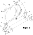
- FIG. 3 shows a slightly different embodiment of the gear holder 1.
- the connecting holes 21 and 31 connect the gear holder 1 with connecting elements (also referred to as storage) 7, the torsion 6 at receive their ends and are connected via connecting holes 71 with the machine base frame or foundation.
- connecting holes 21, 31 and 41 connecting bolts are shown in the connecting holes 21, 31 and 41 connecting bolts.
Landscapes
- Engineering & Computer Science (AREA)
- Mechanical Engineering (AREA)
- General Engineering & Computer Science (AREA)
- Food Science & Technology (AREA)
- General Details Of Gearings (AREA)
- Crushing And Grinding (AREA)
- Press Drives And Press Lines (AREA)
- Rolls And Other Rotary Bodies (AREA)
Applications Claiming Priority (1)
| Application Number | Priority Date | Filing Date | Title |
|---|---|---|---|
| DE102015223694.3A DE102015223694A1 (de) | 2015-11-30 | 2015-11-30 | Getriebehalter für eine Rollenpresse und Verfahren zum Ausbau des Getriebes einer Rollenpresse |
Publications (1)
| Publication Number | Publication Date |
|---|---|
| EP3176470A1 true EP3176470A1 (fr) | 2017-06-07 |
Family
ID=57394407
Family Applications (1)
| Application Number | Title | Priority Date | Filing Date |
|---|---|---|---|
| EP16200191.1A Withdrawn EP3176470A1 (fr) | 2015-11-30 | 2016-11-23 | Support d'engrenage pour une presse à laminer et procédé de dépose d'un engrenage d'une presse à laminer |
Country Status (9)
| Country | Link |
|---|---|
| US (1) | US20170157616A1 (fr) |
| EP (1) | EP3176470A1 (fr) |
| AU (1) | AU2016262675B2 (fr) |
| CA (1) | CA2949110C (fr) |
| CL (1) | CL2016003058A1 (fr) |
| DE (1) | DE102015223694A1 (fr) |
| EA (1) | EA032027B1 (fr) |
| MX (1) | MX2016015689A (fr) |
| PE (1) | PE20170880A1 (fr) |
Cited By (1)
| Publication number | Priority date | Publication date | Assignee | Title |
|---|---|---|---|---|
| EP3978783A1 (fr) * | 2020-09-30 | 2022-04-06 | Flender GmbH | Agencement pourvu de bride de boitier et de support de couple, procédé |
Families Citing this family (1)
| Publication number | Priority date | Publication date | Assignee | Title |
|---|---|---|---|---|
| CN109624375B (zh) * | 2018-12-26 | 2021-07-30 | 江苏徐工工程机械研究院有限公司 | 垃圾处理装置支撑框架和垃圾处理装置 |
Citations (5)
| Publication number | Priority date | Publication date | Assignee | Title |
|---|---|---|---|---|
| EP0035109A1 (fr) * | 1980-03-01 | 1981-09-09 | MANNESMANN Aktiengesellschaft | Support absorbeur de couple pour commandes suspendues à l'arbre de basculement, particulièrement pour commandes de basculement de couvertisseurs |
| DE8712742U1 (de) * | 1987-09-22 | 1987-11-05 | Grachtrup, Heinz, Dipl.-Ing., 4722 Ennigerloh | Walzenmühle |
| DE69410422T2 (de) * | 1993-12-20 | 1998-11-05 | Messian Durand Cie Engrenages | Drehantrieb für ein Zahnrad mit grossem Durchmesser |
| EP1099881A2 (fr) * | 1999-11-12 | 2001-05-16 | Atecs Mannesmann AG | Support de couple et procédé de fabrication de celui-ci |
| CN203764314U (zh) * | 2014-01-10 | 2014-08-13 | 中信重工机械股份有限公司 | 一种无壳体式对辊挤压机 |
Family Cites Families (9)
| Publication number | Priority date | Publication date | Assignee | Title |
|---|---|---|---|---|
| US2606453A (en) * | 1950-04-26 | 1952-08-12 | Dodge Mfg Corp | Machinery drive |
| US2882739A (en) * | 1950-10-19 | 1959-04-21 | American Pulley Co | Speed change transmission devices and supports therefor |
| DE3707015A1 (de) * | 1987-03-05 | 1988-09-15 | Krupp Polysius Ag | Walzenmuehle |
| DE4024109A1 (de) * | 1990-07-30 | 1992-02-06 | Kloeckner Humboldt Deutz Ag | Zweiwalzenmaschine, insbesondere rollenpresse |
| DE9217285U1 (de) * | 1992-12-17 | 1993-03-25 | A. Friedr. Flender AG, 4290 Bocholt | Drehmomentstütze |
| DE4404634A1 (de) * | 1994-02-14 | 1995-08-17 | Krupp Polysius Ag | Walzenmühle |
| DE102005061085A1 (de) * | 2005-12-21 | 2007-06-28 | Khd Humboldt Wedag Gmbh | Zweiwalzenmaschine insbesondere zur Gutbettzerkleinerung |
| US8075442B2 (en) * | 2008-09-05 | 2011-12-13 | General Electric Company | System and assembly for power transmission and generation in a wind turbine |
| CN103721783B (zh) * | 2014-01-10 | 2016-03-23 | 中信重工机械股份有限公司 | 一种无壳体式对辊挤压机 |
-
2015
- 2015-11-30 DE DE102015223694.3A patent/DE102015223694A1/de not_active Ceased
-
2016
- 2016-11-21 CA CA2949110A patent/CA2949110C/fr not_active Expired - Fee Related
- 2016-11-23 PE PE2016002278A patent/PE20170880A1/es unknown
- 2016-11-23 AU AU2016262675A patent/AU2016262675B2/en not_active Ceased
- 2016-11-23 EP EP16200191.1A patent/EP3176470A1/fr not_active Withdrawn
- 2016-11-29 EA EA201650052A patent/EA032027B1/ru not_active IP Right Cessation
- 2016-11-29 MX MX2016015689A patent/MX2016015689A/es unknown
- 2016-11-29 CL CL2016003058A patent/CL2016003058A1/es unknown
- 2016-11-30 US US15/365,594 patent/US20170157616A1/en not_active Abandoned
Patent Citations (5)
| Publication number | Priority date | Publication date | Assignee | Title |
|---|---|---|---|---|
| EP0035109A1 (fr) * | 1980-03-01 | 1981-09-09 | MANNESMANN Aktiengesellschaft | Support absorbeur de couple pour commandes suspendues à l'arbre de basculement, particulièrement pour commandes de basculement de couvertisseurs |
| DE8712742U1 (de) * | 1987-09-22 | 1987-11-05 | Grachtrup, Heinz, Dipl.-Ing., 4722 Ennigerloh | Walzenmühle |
| DE69410422T2 (de) * | 1993-12-20 | 1998-11-05 | Messian Durand Cie Engrenages | Drehantrieb für ein Zahnrad mit grossem Durchmesser |
| EP1099881A2 (fr) * | 1999-11-12 | 2001-05-16 | Atecs Mannesmann AG | Support de couple et procédé de fabrication de celui-ci |
| CN203764314U (zh) * | 2014-01-10 | 2014-08-13 | 中信重工机械股份有限公司 | 一种无壳体式对辊挤压机 |
Cited By (2)
| Publication number | Priority date | Publication date | Assignee | Title |
|---|---|---|---|---|
| EP3978783A1 (fr) * | 2020-09-30 | 2022-04-06 | Flender GmbH | Agencement pourvu de bride de boitier et de support de couple, procédé |
| WO2022069288A1 (fr) | 2020-09-30 | 2022-04-07 | Flender Gmbh | Ensemble ayant une bride de carter et une pièce supportant un couple, et procédé |
Also Published As
| Publication number | Publication date |
|---|---|
| US20170157616A1 (en) | 2017-06-08 |
| EA201650052A3 (ru) | 2018-04-30 |
| EA032027B1 (ru) | 2019-03-29 |
| MX2016015689A (es) | 2017-10-16 |
| CA2949110C (fr) | 2018-09-18 |
| CL2016003058A1 (es) | 2017-06-30 |
| AU2016262675A1 (en) | 2017-06-15 |
| DE102015223694A1 (de) | 2017-06-01 |
| EA201650052A2 (ru) | 2017-05-31 |
| PE20170880A1 (es) | 2017-07-07 |
| AU2016262675B2 (en) | 2018-04-12 |
| CA2949110A1 (fr) | 2017-05-30 |
Similar Documents
| Publication | Publication Date | Title |
|---|---|---|
| AT504640B1 (de) | Biegemaschine | |
| EP2154367B1 (fr) | Procédé de montage d'un moyeu d'hélice sur un arbre de rotor d'une éolienne et éolienne | |
| EP3256273B1 (fr) | Système de presses à découper | |
| DE69837724T2 (de) | Befestigungsverfahren für die brechplatte eines backenbrechers und backenbrecher | |
| DE1908362A1 (de) | Schmiedemaschine mit verstellbaren Schmiedesaetteln | |
| DE102011116548B4 (de) | Presse | |
| EP3176470A1 (fr) | Support d'engrenage pour une presse à laminer et procédé de dépose d'un engrenage d'une presse à laminer | |
| EP2719504A1 (fr) | Dispositif de serrage pour l'étirement d'un boulon fileté | |
| EP3023185B1 (fr) | Outil entraîné en rotation autour d'un axe de rotation ou d'oscillation comprenant un profil d'entraînement destiné a s'accoupler à un profil d'entraînement | |
| DE102012223469A1 (de) | Verbindungselement und Herstellungsverfahren für ein Verbindungselement | |
| DE102009049691A1 (de) | Dichtungsanordnung an einem Dampfturbinengehäuse, umfassend einen fixierbaren Dichtring | |
| CH712345B1 (de) | Vorrichtung mit einer Halteeinrichtung für die Positionierung einer Schraubenmutter einer Schraubenverbindung bei Überkopfmontage. | |
| DE20113561U1 (de) | Werkzeug zum Ein- und Ausbauen von Lagerelementen | |
| EP2153002A1 (fr) | Pignon | |
| DE3030791A1 (de) | Vorrichtung zum gezielten anheben einer last | |
| WO2019096839A1 (fr) | Outil de démontage et de montage de paliers et procédé de remplacement d'un palier | |
| DE102009049690A1 (de) | Dichtungsanordnung an einem Dampfturbinengehäuse, umfassend einen justierbaren Dichtring | |
| DE102014101464A1 (de) | Befestigungseinrichtung | |
| AT524666B1 (de) | Siebkasten mit einem Rahmen und einem umfangsseitig Spannanker aufweisenden Siebbelag | |
| DE68918917T2 (de) | Stauchpresse mit horizontal gegenüberliegenden Stempeln. | |
| EP3938196B1 (fr) | Presse à estamper | |
| DE102009057436B4 (de) | Anordnung zum Einstellen einer Position eines Motors auf einer Platte | |
| DE102008045478A1 (de) | Aufspannblock und System von Aufspannblöcken | |
| DE2823673A1 (de) | Drehmomentstuetze fuer den antriebsblock eines stetigfoerderers | |
| EP2881218B1 (fr) | Lunette destinée au soutien d'une pièce usinée |
Legal Events
| Date | Code | Title | Description |
|---|---|---|---|
| AK | Designated contracting states |
Kind code of ref document: A1 Designated state(s): AL AT BE BG CH CY CZ DE DK EE ES FI FR GB GR HR HU IE IS IT LI LT LU LV MC MK MT NL NO PL PT RO RS SE SI SK SM TR |
|
| AX | Request for extension of the european patent |
Extension state: BA ME |
|
| PUAI | Public reference made under article 153(3) epc to a published international application that has entered the european phase |
Free format text: ORIGINAL CODE: 0009012 |
|
| 17P | Request for examination filed |
Effective date: 20170720 |
|
| RBV | Designated contracting states (corrected) |
Designated state(s): AL AT BE BG CH CY CZ DE DK EE ES FI FR GB GR HR HU IE IS IT LI LT LU LV MC MK MT NL NO PL PT RO RS SE SI SK SM TR |
|
| STAA | Information on the status of an ep patent application or granted ep patent |
Free format text: STATUS: THE APPLICATION IS DEEMED TO BE WITHDRAWN |
|
| 18D | Application deemed to be withdrawn |
Effective date: 20200603 |