EP3175523B1 - Dispositif de guidage - Google Patents
Dispositif de guidage Download PDFInfo
- Publication number
- EP3175523B1 EP3175523B1 EP15736421.7A EP15736421A EP3175523B1 EP 3175523 B1 EP3175523 B1 EP 3175523B1 EP 15736421 A EP15736421 A EP 15736421A EP 3175523 B1 EP3175523 B1 EP 3175523B1
- Authority
- EP
- European Patent Office
- Prior art keywords
- wall elements
- wall
- guide device
- region
- guide
- Prior art date
- Legal status (The legal status is an assumption and is not a legal conclusion. Google has not performed a legal analysis and makes no representation as to the accuracy of the status listed.)
- Active
Links
- 238000000926 separation method Methods 0.000 claims description 5
- 239000004033 plastic Substances 0.000 claims description 3
- 230000005540 biological transmission Effects 0.000 description 5
- 238000000034 method Methods 0.000 description 3
- 238000003780 insertion Methods 0.000 description 2
- 230000037431 insertion Effects 0.000 description 2
- 238000009434 installation Methods 0.000 description 2
- 230000008719 thickening Effects 0.000 description 2
- 238000000151 deposition Methods 0.000 description 1
- 230000000694 effects Effects 0.000 description 1
- 210000003746 feather Anatomy 0.000 description 1
- 238000002347 injection Methods 0.000 description 1
- 239000007924 injection Substances 0.000 description 1
- 239000002991 molded plastic Substances 0.000 description 1
- 239000000243 solution Substances 0.000 description 1
Images


Classifications
-
- H—ELECTRICITY
- H02—GENERATION; CONVERSION OR DISTRIBUTION OF ELECTRIC POWER
- H02G—INSTALLATION OF ELECTRIC CABLES OR LINES, OR OF COMBINED OPTICAL AND ELECTRIC CABLES OR LINES
- H02G3/00—Installations of electric cables or lines or protective tubing therefor in or on buildings, equivalent structures or vehicles
- H02G3/02—Details
- H02G3/04—Protective tubing or conduits, e.g. cable ladders or cable troughs
- H02G3/0437—Channels
-
- H—ELECTRICITY
- H02—GENERATION; CONVERSION OR DISTRIBUTION OF ELECTRIC POWER
- H02G—INSTALLATION OF ELECTRIC CABLES OR LINES, OR OF COMBINED OPTICAL AND ELECTRIC CABLES OR LINES
- H02G3/00—Installations of electric cables or lines or protective tubing therefor in or on buildings, equivalent structures or vehicles
- H02G3/02—Details
- H02G3/06—Joints for connecting lengths of protective tubing or channels, to each other or to casings, e.g. to distribution boxes; Ensuring electrical continuity in the joint
- H02G3/0608—Joints for connecting non cylindrical conduits, e.g. channels
-
- F—MECHANICAL ENGINEERING; LIGHTING; HEATING; WEAPONS; BLASTING
- F16—ENGINEERING ELEMENTS AND UNITS; GENERAL MEASURES FOR PRODUCING AND MAINTAINING EFFECTIVE FUNCTIONING OF MACHINES OR INSTALLATIONS; THERMAL INSULATION IN GENERAL
- F16G—BELTS, CABLES, OR ROPES, PREDOMINANTLY USED FOR DRIVING PURPOSES; CHAINS; FITTINGS PREDOMINANTLY USED THEREFOR
- F16G13/00—Chains
- F16G13/12—Hauling- or hoisting-chains so called ornamental chains
- F16G13/16—Hauling- or hoisting-chains so called ornamental chains with arrangements for holding electric cables, hoses, or the like
-
- F—MECHANICAL ENGINEERING; LIGHTING; HEATING; WEAPONS; BLASTING
- F16—ENGINEERING ELEMENTS AND UNITS; GENERAL MEASURES FOR PRODUCING AND MAINTAINING EFFECTIVE FUNCTIONING OF MACHINES OR INSTALLATIONS; THERMAL INSULATION IN GENERAL
- F16L—PIPES; JOINTS OR FITTINGS FOR PIPES; SUPPORTS FOR PIPES, CABLES OR PROTECTIVE TUBING; MEANS FOR THERMAL INSULATION IN GENERAL
- F16L3/00—Supports for pipes, cables or protective tubing, e.g. hangers, holders, clamps, cleats, clips, brackets
- F16L3/26—Supports for pipes, cables or protective tubing, e.g. hangers, holders, clamps, cleats, clips, brackets specially adapted for supporting the pipes all along their length, e.g. pipe channels or ducts
-
- G—PHYSICS
- G02—OPTICS
- G02B—OPTICAL ELEMENTS, SYSTEMS OR APPARATUS
- G02B6/00—Light guides; Structural details of arrangements comprising light guides and other optical elements, e.g. couplings
- G02B6/44—Mechanical structures for providing tensile strength and external protection for fibres, e.g. optical transmission cables
- G02B6/4439—Auxiliary devices
- G02B6/4459—Ducts; Conduits; Hollow tubes for air blown fibres
-
- H—ELECTRICITY
- H02—GENERATION; CONVERSION OR DISTRIBUTION OF ELECTRIC POWER
- H02G—INSTALLATION OF ELECTRIC CABLES OR LINES, OR OF COMBINED OPTICAL AND ELECTRIC CABLES OR LINES
- H02G11/00—Arrangements of electric cables or lines between relatively-movable parts
- H02G11/006—Arrangements of electric cables or lines between relatively-movable parts using extensible carrier for the cable, e.g. self-coiling spring
-
- H—ELECTRICITY
- H02—GENERATION; CONVERSION OR DISTRIBUTION OF ELECTRIC POWER
- H02G—INSTALLATION OF ELECTRIC CABLES OR LINES, OR OF COMBINED OPTICAL AND ELECTRIC CABLES OR LINES
- H02G3/00—Installations of electric cables or lines or protective tubing therefor in or on buildings, equivalent structures or vehicles
- H02G3/02—Details
- H02G3/04—Protective tubing or conduits, e.g. cable ladders or cable troughs
- H02G3/0406—Details thereof
- H02G3/0418—Covers or lids; Their fastenings
-
- H—ELECTRICITY
- H02—GENERATION; CONVERSION OR DISTRIBUTION OF ELECTRIC POWER
- H02G—INSTALLATION OF ELECTRIC CABLES OR LINES, OR OF COMBINED OPTICAL AND ELECTRIC CABLES OR LINES
- H02G3/00—Installations of electric cables or lines or protective tubing therefor in or on buildings, equivalent structures or vehicles
- H02G3/02—Details
- H02G3/04—Protective tubing or conduits, e.g. cable ladders or cable troughs
- H02G3/0456—Ladders or other supports
Definitions
- the invention relates to a guide device for a line, in particular for a power transmission chain, wherein the line is movable such that an upper portion thereof is positioned over a lower portion, and both sections are interconnected by an arcuate portion, wherein the guide means at least in one Area laterally opposite guide walls for guiding the upper portion and / or the lower portion, which consist of laterally opposite wall elements, each two facing away from each other in the longitudinal direction of the wall element end faces, a direction away from the laterally opposite wall element outside, one to the laterally opposite wall element indicative inside, have an upper side and a lower side, wherein the wall elements forming a guide wall are connected to each other in the region of their front ends, so that they at their Inne n beau form a over the entire guide wall extending continuous guide surface, wherein the wall elements are integrally molded plastic, in the region of their front ends integrally formed first fastening means for positive and / or non-positive fixing to an immediately adjacent wall element against separation of this and pivoting have this in any direction.
- the above-mentioned upper portion of the line, in particular energy chain, is also referred to as upper run and the lower portion of the line as Untertrum.
- a guide device of the aforementioned type is known from DE 103 23 681 A1 known.
- the retaining rail system for guiding energy chains on opposite wall elements which are approximately triangular in cross-section and form with its approximately vertical inside a guide wall for the energy supply chain.
- a horizontally arranged cylinder or a protrusion with spherical thickening is arranged in the longitudinal direction, while inside the other wall element a hollow cylinder corresponding to the cylinder or a hollow cylinder corresponding to the spherical thickening is provided.
- These fasteners are used for latching connection facing each other end faces immediately adjacent wall elements.
- the present invention has for its object to improve such guide walls having guide means to the effect that it can be easily mounted, wherein the guide walls forming wall elements can be stably connected to each other.
- the object is achieved by a guide device of the type mentioned above in that the wall elements in the region of their front ends to the opposite wall element directed webs, which are interconnected by interposition of a gutter, and that the adjacent webs of two immediately adjacent wall elements together Form latching means for connection to a gutter.
- intermediate webs can be provided with different lengths, which are detachably connected to the integrally formed on the wall elements webs.
- the adjacent webs of two immediately adjacent wall elements together form a locking means for connection to a gutter.
- the cohesion of immediately adjacent wall elements is further increased.
- the first attachment means for connecting immediately adjacent wall elements may in particular be designed such that portions of the guide means comprising several wall elements having guide walls without further (separate) fasteners form stable components that are safe to handle during transport and assembly and cantilevered over its entire length away are.
- the wall elements may e.g. have a length between 0.5m and 1m.
- the first fastening means for connecting adjacent wall elements may further be configured such that only every second or third wall element of a guide wall of the guide means is mounted on a base, e.g. a console in a crane system, must be attached.
- the wall elements are integrally formed on these second fastening means for fastening the wall elements on a base or the like.
- both guide walls can be identical to one another.
- the wall elements over their entire height can have a substantially equal wall thickness.
- the wall elements in the region of their top are preferably outward bent.
- the wall elements in the region of one of its two front ends may have at least one protrusion projecting on the end face in question and an opening corresponding to the protrusion in the region of the other end face into which the protrusion of an immediately adjacent wall element can be introduced.
- the wall elements on flat end faces.
- the wall elements in the region of its two front ends on its front side projecting projections which are arranged offset in height at one end face relative to the projection or the projections on the other front end so that they at least partially cover outside areas of an immediately adjacent wall element and at least a projection between two projections engages without height intermediate space.
- the projections are preferably arranged on the outside of the wall elements, so that they at least partially cover the outside of immediately adjacent wall elements.
- the wall elements in the region of its two end-side ends integrally formed with each other corresponding locking means which are designed such that they can enter with the corresponding locking means of an immediately adjacent wall element a locking connection against loosening of the wall elements of each other in the longitudinal direction ,
- the latching means is formed in the region of one of the front ends as a projecting projection on the relevant end face with a latching area and the corresponding latching means in the region of the other end face provided with an opening in the the latching region of the projection of an immediately adjacent wall element can be latched.
- the latching region of the projection may project from the outside of the wall element, wherein the opening corresponding to the latching region is formed in a part projecting from the outside of the wall element.
- the opening is window-like formed in this part, wherein the latching area corresponds to the window-like opening.
- the latching region and the part having the opening can protrude in each case half at the respective end face.
- the latching region and the part having the opening in the connected state of the immediately adjacent wall elements may be formed substantially symmetrically with respect to the abutting end faces of the wall elements.
- the second fastening means for fastening the wall elements on a base or the like are preferably designed as attachment tabs extending parallel to the underside of the wall elements, which project with respect to the end faces of the wall elements and overlap with an immediately adjacent wall element when a wall element is connected.
- the fastening straps can extend outwards, in particular on the outside of the wall elements. Alternatively, it can be provided that they extend on the inside of the wall elements in the direction of the respective opposite wall element.
- the groove preferably extends in a direction away from the respective end face of the wall member end portion of a fastening strap transverse to the longitudinal direction of the wall member, while the spring extends in a corresponding, on the other end side of the wall member projecting end portion in the transverse direction.
- guide rails on the inner sides of at least one pair of opposing wall elements for supporting the lower run of a movable in the guide device line, in particular a power transmission chain, in one piece be formed.
- the line in particular a power transmission chain, in which the free end of the lower strand has a relative to the guide means stationary connection and the free end of the upper run a relative to the guide device movable terminal, extend the wall elements with the molded thereon guide rails for the lower run of stationary connection from about the maximum length of the lower strand in the process of the line.
- the upper strand can extend cantilevered over the lower strand or settle on the lower strand after a certain cantilevered length.
- support of the upper strand outside of said first portion of the guide means, i. beyond the stationary connection of the lower run provided in a second section of the guide device.
- the second section extends from the stationary connection point approximately over the maximum length of the upper strand during the process of the line, in particular an energy transmission chain.
- the guide device may comprise wall elements, on whose insides guide rails for the upper run of the line, in particular an energy guide chain, are integrally formed.
- the wall portion of these wall elements can be broken between the first attachment means for connecting immediately adjacent wall elements and optionally second attachment means for fixing the wall elements on a base or the like below the upper run guide rails.
- the one-piece wall elements of said sections are preferably formed identically.
- the opposite wall elements can have separate guide rails for the upper run in their inner sides in the second section of the guide device, which can preferably be fastened in different heights to the wall elements in a positive and / or non-positive manner.
- the guide rails can be designed in the form of an elongated, angularly cross-sectional element, wherein the one leg for attachment to the respective wall element and the substantially perpendicular thereto extending second leg are provided for supporting the upper strand.
- the leg serving for fastening may have knobs directed towards the wall element in the region of its ends and preferably also in the middle region, which engage positively and / or non-positively in openings in the wall elements which correspond to the knobs.
- a plurality of superposed openings may be provided in the wall elements in each case.
- Such wall elements with integrally formed guide rails for the lower run can be used to form said first and second sections of the guide means, wherein only in the second section the separate guide rails for the upper strand are fixed to the wall elements. All wall elements used for the guide device may be identical in this embodiment.
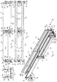
- FIGS. 1a to 1d a section of a first embodiment of a guide device is shown, which comprises two opposite, consisting of two wall elements 1, 2 guide walls.
- Wall elements 1 shown on the bottom right are followed by further wall elements 1, which are identical to the latter, and form a first section of the guide device for depositing the lower run of an energy guiding chain not shown in the drawing.
- wall elements 1 which are identical to the latter, and form a first section of the guide device for depositing the lower run of an energy guiding chain not shown in the drawing.
- FIG. 1a 2 wall elements shown above on the other, with this identical wall elements 2, which serve a second portion of the guide means for supporting and guiding the upper strand of the energy chain.
- resulting guide means is designed so that the free end of the lower run of the energy guide chain leading to a stationary connection, for example between the in FIG. 1a shown wall elements 1, and the upper strand has a relative to the guide device movable terminal.
- Both strands of the energy guiding chain are connected to each other by an arcuate portion, wherein the arcuate portion of the energy guiding chain in the process of the same moves back and forth in said sections of the guide means.
- the upper run can, depending on its length, extend cantilevered over the lower run or rest on the lower run after a certain cantilevered length. If the upper strand extends beyond the said first section, in which it is optionally supported by the lower strand, into the mentioned second section of the guide device, it is supported and guided there by guide rails 3 arranged on the inner side of the wall elements 2.
- the height of the upper side 4 of the guide rails 3 corresponds at least approximately to the height of the lower run of the energy guiding chain arranged in the named first section.
- the wall elements 1, 2 of the first and second sections are each identical to one another and molded in one piece from plastic. How out FIG. 1a It can also be seen that the wall elements 1, 2 forming the two opposite guide walls of the guide device are connected to one another at their mutually facing end sides such that their inner sides 5 have a continuous guide surface for the upper strand extending in the longitudinal direction of the wall elements 1, 2 and in said first section form the lower strand. This means that there are no free spaces between the adjacent inner sides 5 of the wall elements 1, 2 in the region of their mutually facing end faces.
- the wall elements 1, 2 have in the region of their front ends integrally formed first fastening means 6 for positive fixing to an immediately adjacent Wall element 1, 2 against separation of this and pivoting relative to this in any direction.
- the fastening means explained further below are designed such that sections of the guide device form guide components comprising two or three wall elements 1, 2, without further separate fastening means, which are safe to handle and cantilevered during transport and installation over their entire length.
- the wall elements 1, 2 used in the embodiment have a length of 0.5 m and can form a stable two or three wall elements 1, 2 comprehensive component in the interconnected state.
- the wall elements 1, 2 For attachment to a base, which can also consist of brackets, the wall elements 1, 2 in one piece on this molded second fastening means 7.
- the two wall elements 1, 2, of which the said first and second sections of the guide means are composed, are described in greater detail in FIGS FIGS. 2a to 2e or 3a to 3e shown.
- the wall elements 1, 2 have a substantially equal wall thickness over their entire height.
- the wall elements 1, 2 are bent in the region of its upper side 8 to the outside.
- the wall elements 1, 2 have flat end faces 9, 10.
- the first fastening means 6 for connecting immediately adjacent wall elements 1, 2 include projections 11, 12 which protrude in the region of the two front ends of the wall elements 1, 2 on the end faces 9, 10 and on the outer side 13 of the wall element 1, 2.
- the projections 11 at the Front side 9 are offset in height relative to the projections 12 on the end face 10 arranged so that they, as in Figure 1c shown, the outside of an immediately adjacent wall element 1, 2 overlap in the region of the front end and engage without forming a height-wise gap between each other.
- the projections 11, 12 cause an exact height alignment of the wall elements 1, 2 to each other and secure the connection of the wall elements 1, 2 against the solution in a direction transverse to its longitudinal direction.
- the first fastening means 6 for connecting immediate wall elements 1, 2 further include integrally molded on the wall elements 1, 2 molded together locking means 14, 15 in the region of the front ends of the wall elements 1, 2 a.
- the locking means 14 in the region of the end face 10 is formed as a projecting at the relevant end face 10 projection with a latching region 16.
- the locking means 15 corresponding to this latching means 14 in the region of the other end face 9 is provided with a window-like opening 17, into which the latching area 16 of the projection of an immediately adjacent wall element 1, 2 can be latched.
- the latching region 16 of the projection protrudes from the outer side 13 of the wall element 1, 2, wherein the window-like opening 17 corresponding to the latching region 16 is formed in a part 18 projecting from the outside of the wall element 1, 2.
- the latching region 16 and the window-like opening 17 having part 18 are each in front of the front sides 9 and 10 so that they are in the connected state of the immediately adjacent wall elements 1, 2 substantially symmetrically with respect to the abutting end faces 9, 10 of Wall elements 1, 2 are formed, in particular from Figure 1c evident.
- the second fastening means 7 for fastening the wall elements 1, 2 on a base are formed as fixing lugs 20, 21 extending parallel to the underside 19 of the wall elements 1, 2. These are opposite to the end faces 9 and 10 of the wall elements 1, 2 before and overlap when connected to an immediately adjacent wall element 1, 2, in particular from the FIGS. 1a and 1c evident.
- the fastening tabs extend on the outside 13 of the wall elements 1, 2 to the outside.
- a tongue and groove connection is provided for additional protection against separation and tilting of immediately adjacent wall elements.
- the groove 22 extends in one of the respective end face 9 of the wall element 1, 2 pioneering end portion of the fastening tab 21 transversely to the longitudinal direction of the wall element 1, 2, while the spring 23 in a corresponding, on the other end face 10 of the wall element 1, second extending projecting end portion in the transverse direction.
- integrally formed on the outer sides 13 of the wall elements 1, 2 webs 24, 25 are provided, which are spaced from the end faces 9 and 8 and arranged with the attachment tabs 20 and 21 form an angle.
- the fastening tabs 20, 21 opposite, on the inside 5 of the wall element 1, 2 webs 26, 27 molded, which with the webs 27 and 26 of the opposite wall element. 1 , 2 are connectable.
- the webs 26, 27 are provided at their free ends with a locking means 28, 29 which cooperates with a latching means 30 and 31 of a gutter 32 which is disposed between the webs 26 and 27 of the opposite wall elements 1, 2.
- the width of the guide means ie, the distance of the inner sides 5 of the opposite wall elements 1, 2 are adapted to the width of the leading to energy supply chain.
- the fastening straps 20, 21 have openings which, when the fastening straps of immediately adjacent wall elements 1, 2 overlap one another, serve to carry fastening screws or bolts.
- the webs 26, 27 are in connection with immediately adjacent wall elements 1, 2, as in FIG. 1b shown, against each other and form a bridge pair.
- the latching means 28, 29 of the pair of webs form a latching means which cooperates with the opposite latching means 30, 31 of a gutter 32 for producing a stable attachment.
- 1 guide rails 33 are integrally molded on the inner sides 5 of the wall elements for supporting the lower strand of the energy supply chain to be inserted.
- the guide rails extend between the webs 26 and 27 and have with them a continuous top 34 at the same level.
- attachment regions 35, 36 The end-side end regions of the wall elements 1, 2, which enclose the first fastening means 6 for positive and / or frictional attachment to an immediately adjacent wall element 1, 2, are referred to below as attachment regions 35, 36.
- the wall portions 39 and 40 of the wall elements 1 extend substantially over the entire height of the mounting portions 35 and 36, since they lead both the lower strand and the upper strand of the energy supply chain to be inserted laterally. Between these guide areas and the attachment areas 35 and 36, the wall elements 1 have convex bulges 41 for increasing the stability of the wall elements 1 against transversely acting forces on the guide device.
- the wall portions 42 of the wall elements 2 extend between the mounting portions 35 and 36 between the molded onto the inside 5 guide rail 3 and the same height level as the wall elements 1 arranged top 8.
- the space below the wall portion 42 between the mounting portions 35 and 36 is open.
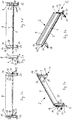
- FIGS. 4a to 4e a portion of another embodiment of a guide device is shown, which in the same place as in the FIGS. 1a to 1d shown portion is arranged in the guide device. Only the differences between the wall elements 45 used in this embodiment and the wall elements 1, 2 discussed above will be explained below. Regarding the others in the FIGS. 4a to 4e and 5a to 5e shown details of the wall elements 45 is made to the first embodiment described above.
- All wall elements 45 of the second embodiment of a guide device are identical and injection molded in one piece from plastic.
- the wall elements 45 correspond to the wall elements 1 of the first exemplary embodiment except for a device for arranging a separate guide rail 46 at different heights on the inner side 5 of the wall element 45.
- the guide rails 46 are, as in particular from the FIGS. 6a to 6e shows, in the form of an elongated, angularly shaped in cross-section element, wherein the one leg 47 is provided for attachment to the respective wall element 45 and the substantially perpendicular thereto extending second leg 48 for supporting the upper strand.
- the serving for fastening leg 47 has the wall member 45 directed toward nubs 49 in the region of its ends and in the central region, which engage positively and non-positively in corresponding with the nubs openings 50 in the wall member 45.
- a plurality of superimposed openings 50 are provided in the wall elements 45, respectively.
- Such wall elements 45 which further comprise guide rails 33 integrally formed thereon for the lower run, are used to form the above-mentioned first and second sections of the guide device, wherein the separate guide rails 46 for the upper run are fastened to the wall elements 45 only in the second section.
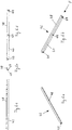
- FIGS. 7a to 7e In a third embodiment of a guide means wall elements 51 are used, as you in the FIGS. 7a to 7e are shown.
- wall area between the attachment areas 35 and 36 has a window-like opening 52. This extends in height with a certain distance from the integrally molded thereto guide rail 33, which is sufficient for lateral guidance of the lower strand, to about the outwardly bent portion at the top of the wall member 51st
- the wall member 51 may be used in a guide device instead of the wall member 1 of the above-described first embodiment, a guide means together with wall members 2 or wall members 45 of the second embodiment described above.
- the wall elements 51 may alternatively be used to form a guide means for the lower strand formed as an extension channel.
Claims (15)
- Dispositif de guidage pour une ligne, en particulier pour une chaîne de guidage d'énergie, dans lequel la ligne peut être déplacée d'une manière telle qu'une partie supérieure de celle-ci peut être positionnée au-dessus d'une partie inférieure et que les deux parties sont interreliées par une partie courbée, dans lequel le dispositif de guidage présente, au moins dans une région, des parois de guidage latéralement opposées pour guider la partie supérieure et/ou la partie inférieure et composées des éléments de paroi (1, 2, 45, 51) latéralement opposés respectivement comportant deux faces frontales (9, 10) pointant à l'opposé l'une de l'autre dans la direction longitudinale de l'élément de paroi (1, 2, 45, 51), une face extérieure (13) pointant à l'opposé de l'élément de paroi (1, 2, 45, 31) latéralement opposé, une face intérieure (5) pointant vers l'élément de paroi (1, 2, 45, 51) latéralement opposé, une face supérieure (8) et une face inférieure (18), dans lequel les éléments de paroi (1, 2, 45, 31) formant une paroi de guidage sont interreliés dans la zone de ses extrémités frontales d'une manière à former, à ses faces intérieures (5), une surface de guidage continue s'étendant sur toute la paroi de guidage, dans lequel les éléments de paroi (1, 2, 45, 51) sont moulés d'une seule pièce en plastique et comportent, dans la zone de ses extrémités frontales, des premiers moyens de fixation (6) formés d'un seul tenant sur ces extrémités frontales, pour la fixation sur un élément de paroi (1, 2, 45, 51) immédiatement adjacent par liaison de forme et/ou de force pour éviter une séparation de celui-ci et un pivotement par rapport à celui-ci dans une direction quelconque, caractérisé en ce que les éléments de paroi (1, 2, 45, 51) présentent, dans la zone de ses extrémités frontales, des nervures (26, 27) qui sont orientées vers l'élément de paroi (1, 2, 45, 51) opposé et qui peuvent être reliées entre eux par intercalation d'une nervure intermédiaire (32), et que les nervures adjacentes (26, 27) de deux éléments de paroi immédiatement adjacents (1, 2, 45, 51) forment, ensemble, un moyen d'encliquetage pour la liaison avec une nervure intermédiaire (32).
- Dispositif de guidage selon la revendication 1, caractérisé en ce que les éléments de paroi (1, 2, 45, 51) comportent des deuxièmes moyens de fixation formés d'un seul tenant sur lesdits éléments de paroi, pour la fixation des éléments de paroi (1, 2, 45, 51) sur une base ou similaire.
- Dispositif de guidage selon la revendication ou 2, caractérisé en ce que les éléments de paroi des deux parois de guidage sont formés de manière identique les uns aux autres.
- Dispositif de guidage selon l'une des revendications 1 à 3, caractérisé en ce que les éléments de paroi (1, 2, 45, 51) présentent une épaisseur de paroi sensiblement égale sur toute leur hauteur.
- Dispositif de guidage selon l'une des revendications 1 à 4, caractérisé en ce que les éléments de paroi (1, 2, 45, 51) présentent des faces frontales (9, 10) planes.
- Dispositif de guidage selon la revendication 5, caractérisé en ce que les éléments de paroi (1, 2, 45, 51) présentent, dans la région de ses extrémités frontales sur leur face frontale (9, 10), des protubérances saillantes (11, 12) disposées à une extrémité frontale de manière décalée en hauteur par rapport à la protubérance ou aux protubérances (11 ou 12) à l'autre extrémité frontale et de telle manière que celles-ci chevauchent des parties sur le côté extérieur d'un élément de paroi (1, 2, 45, 51) immédiatement adjacent, au moins en partie, et qu'au moins une protubérance (11) s'engage entre deux protubérances (12) sans aucune espace intermédiaire en hauteur.
- Dispositif de guidage selon l'une des revendications 1 á 6, caractérisé en ce que les éléments de paroi (1, 2, 45, 51) présentent, dans la région de ses deux extrémités frontales, des moyens d'encliquetage (14, 15) correspondant les uns aux autres et formés d'un seul tenant sur lesdites extrémités frontales, moyens d'encliquetage qui sont configurés de sorte qu'ils forment, avec le moyen d'encliquetage (15, 14) correspondant d'un élément de paroi (1, 2, 45, 51) immédiatement adjacent, une liaison à encliquetage pour éviter le détachement des éléments de paroi (1, 2, 45, 51) dans leur direction longitudinale.
- Dispositif de guidage selon la revendication 7, caractérisé en ce que le moyen d'encliquetage (14) est formé, dans la région de l'une des extrémités frontales, comme une protubérance saillant sur la face frontale (10) respective et comprenant une partie d'encliquetage (16), et le moyen d'encliquetage correspondant (15) est muni, dans la région de l'autre des extrémités frontales, d'un orifice (17) dans lequel la partie d'encliquetage (16) de la protubérance d'un élément de paroi (1, 2, 45, 51) immédiatement adjacent peut être encliqueté.
- Dispositif de guidage selon la revendication 8, caractérisé en ce que la partie d'encliquetage (16) de la protubérance fait saillie sur la face extérieure (13) de l'élément de paroi (1, 2, 45, 51), l'orifice (17) qui correspond avec la partie d'encliquetage (16) étant formé dans une partie (18) faisant saillie sur la face extérieure (13) de l'élément de paroi (1, 2, 45, 51).
- Dispositif de guidage selon l'une des revendications 2 à 9, caractérisé en ce que les deuxièmes moyens de fixation (7) destinés á la fixation des éléments de paroi (1, 2, 45, 51) sur une base ou similaire sont formés comme des pattes de fixation (20, 21) s'étendant parallèlement à la face inférieure (19) des éléments de paroi (1, 2, 45, 51), pattes qui font saillie par rapport aux faces frontales (9, 10) des éléments de paroi (1, 2, 45, 51) et se chevauchent lors de la liaison d'un élément de paroi (1, 2, 45, 51) avec un élément de paroi (1, 2, 45, 51) immédiatement adjacent.
- Dispositif de guidage selon la revendication 10, caractérisé en ce que les pattes de fixation (20, 21) s'étendent vers l'extérieur sur la face extérieure (12) des éléments de paroi (1, 2, 45, 51).
- Dispositif de guidage selon la revendication 11, caractérisé en ce que, dans les régions de chevauchement des pattes de fixation (10, 21), est prévue une liaison à rainure-languette.
- Dispositif de guidage selon l'une des revendications 10 à 12, caractérisé en ce que, dans la région des extrémités frontales des éléments de paroi (1, 2, 45, 51), sont prévus des nervures (24, 25) s'étendant vers la face supérieure de ceux-ci et formées d'un seul tenant sur les faces extérieures (13) des éléments de paroi (1, 2, 45, 51), lesdites nervures étant espacées des faces frontales (9, 10) et formant un angle avec les pattes de fixation (20, 21).
- Dispositif de guidage selon l'une des revendications 1 à 13, caractérisé en ce que des rails de guidage (33) pour supporter la partie inférieure d'une ligne déplaçable dans le dispositif de guidage, particulièrement d'une chaîne de guidage d'énergie, sont formés d'un seul tenant sur les faces intérieures (5) d'au moins une paire des éléments de parois opposés.
- Dispositif de guidage selon l'une des revendications 1 à 14, caractérisé en ce que des rails de guidage (33) pour supporter la partie supérieure d'une ligne déplaçable dans le dispositif de guidage, particulièrement d'une chaîne de guidage d'énergie, sont formés d'un seul tenant sur les faces intérieures (5) d'au moins une paire des éléments de parois (1, 2, 45, 51) opposés.
Priority Applications (1)
| Application Number | Priority Date | Filing Date | Title |
|---|---|---|---|
| PL15736421T PL3175523T3 (pl) | 2014-07-31 | 2015-07-01 | Urządzenie prowadzące |
Applications Claiming Priority (2)
| Application Number | Priority Date | Filing Date | Title |
|---|---|---|---|
| DE202014103562.1U DE202014103562U1 (de) | 2014-07-31 | 2014-07-31 | Führungseinrichtung |
| PCT/EP2015/065000 WO2016015942A1 (fr) | 2014-07-31 | 2015-07-01 | Dispositif de guidage |
Publications (2)
| Publication Number | Publication Date |
|---|---|
| EP3175523A1 EP3175523A1 (fr) | 2017-06-07 |
| EP3175523B1 true EP3175523B1 (fr) | 2018-05-02 |
Family
ID=51629329
Family Applications (1)
| Application Number | Title | Priority Date | Filing Date |
|---|---|---|---|
| EP15736421.7A Active EP3175523B1 (fr) | 2014-07-31 | 2015-07-01 | Dispositif de guidage |
Country Status (9)
| Country | Link |
|---|---|
| US (1) | US10693285B2 (fr) |
| EP (1) | EP3175523B1 (fr) |
| JP (1) | JP6543694B2 (fr) |
| KR (1) | KR101962549B1 (fr) |
| CN (1) | CN107005036B (fr) |
| CA (1) | CA2956720C (fr) |
| DE (1) | DE202014103562U1 (fr) |
| PL (1) | PL3175523T3 (fr) |
| WO (1) | WO2016015942A1 (fr) |
Families Citing this family (8)
| Publication number | Priority date | Publication date | Assignee | Title |
|---|---|---|---|---|
| WO2019046924A1 (fr) * | 2017-09-11 | 2019-03-14 | Melquisedec Francisquini | Agencement structural appliqué à un bus conducteur |
| DE202017105927U1 (de) * | 2017-09-28 | 2019-01-08 | Igus Gmbh | Führungseinrichtung |
| DE202018101686U1 (de) * | 2018-03-26 | 2018-04-09 | Igus Gmbh | Energieführungskette und Trennsteg hierfür |
| CA3049381A1 (fr) * | 2018-07-13 | 2020-01-13 | Eaton Intelligent Power Limited | Element de jonction d`un chemin de cables |
| DE202019107117U1 (de) * | 2019-12-19 | 2021-04-19 | Igus Gmbh | Energieführungskette und Speichereinheit für eine Energieführungskette |
| DE202020101247U1 (de) * | 2020-03-06 | 2021-06-09 | Igus Gmbh | Vertikal-Führungsrinne |
| DE202020103942U1 (de) * | 2020-07-08 | 2020-07-27 | Tsubaki Kabelschlepp GmbH | Auflage für eine Energieführungskette |
| US11433830B2 (en) * | 2020-10-01 | 2022-09-06 | Deere & Company | Wire harness tray assembly |
Citations (1)
| Publication number | Priority date | Publication date | Assignee | Title |
|---|---|---|---|---|
| DE10323681A1 (de) * | 2003-05-22 | 2004-12-16 | Rüttiger, Maximilian, Dipl.-Ing. (FH) | Halteschienensystem für Energieführungsketten |
Family Cites Families (63)
| Publication number | Priority date | Publication date | Assignee | Title |
|---|---|---|---|---|
| US1770212A (en) * | 1927-05-04 | 1930-07-08 | Charles W Keplinger | Wiring trough |
| US2161492A (en) * | 1928-08-21 | 1939-06-06 | Wadsworth Electric Mfg Co | Means for bank switch installations |
| US2658708A (en) * | 1950-03-17 | 1953-11-10 | Grosse Fred | Stand for flatirons |
| US2905201A (en) * | 1953-09-30 | 1959-09-22 | Gen Electric | Sectional wiring duct |
| NL253817A (fr) * | 1959-07-21 | 1900-01-01 | Burndy Corp | |
| US3042351A (en) * | 1960-05-27 | 1962-07-03 | Bois Marvin A Du | Cable trays |
| US3338599A (en) * | 1965-06-30 | 1967-08-29 | Square D Co | Transposition section for lay-in duct |
| US3370121A (en) * | 1967-06-26 | 1968-02-20 | Danzer Metal Works Co | Rf energy retaining raceway for communications cables |
| US3680817A (en) * | 1969-11-28 | 1972-08-01 | Electrovert Ltd | Multi-way cable troughs |
| DE2337628A1 (de) * | 1973-07-24 | 1975-02-06 | Intermercury Finance & Trad | Installationskanal |
| US3915420A (en) * | 1974-10-07 | 1975-10-28 | Crouse Hinds Co | Cable tray |
| US4080742A (en) * | 1974-11-04 | 1978-03-28 | Osterried James L | Kit of parts for forming a curved member, and curved member formed thereby |
| IT1036717B (it) * | 1975-07-25 | 1979-10-30 | Visentin Andrea | Canalizzazione ad elementi prefab bricati in due parti e componibili fra lord |
| FR2337451A1 (fr) | 1975-12-31 | 1977-07-29 | Technilec Sarl | Conduit pour fils de distribution electrique et de signaux dans les batiments |
| US4077434A (en) | 1976-05-27 | 1978-03-07 | Federal Cartridge Corporation | Sealed lay-in conduit duct |
| FR2556517B1 (fr) * | 1983-12-07 | 1986-09-26 | Legrand Sa | Goulotte composite, a corps en matiere synthetique et element(s) de revetement en metal, notamment pour logement de cables electriques |
| DE4140910C1 (fr) | 1991-12-12 | 1993-02-25 | Kabelschlepp Gmbh, 5900 Siegen, De | |
| US5465929A (en) * | 1993-08-19 | 1995-11-14 | B-Line Systems, Inc. | Ladder-type cable tray system |
| DE4445403B4 (de) * | 1993-12-27 | 2006-04-06 | Mirai Industry Co, Ltd. | Kabelgestell und Kabelgestellhalter |
| US5602364A (en) * | 1994-04-08 | 1997-02-11 | Buchanan Construction Products, Inc. | Panel Channel |
| JPH08275333A (ja) * | 1994-10-18 | 1996-10-18 | Artwright Technol Sdn Bhd | 電線管ユニットおよび電線管アッセンブリ |
| RU2138708C1 (ru) * | 1995-04-03 | 1999-09-27 | Игус Шпритцгусстайле Фюр Ди Индустри ГмбХ | Направляющий желоб для энергопроводящих цепей |
| DE29610067U1 (de) * | 1996-06-07 | 1996-08-29 | Igus Gmbh | Führungsrinne für Energieführungsketten |
| DE29610947U1 (de) * | 1996-06-24 | 1996-08-22 | Miranda Giovanni | Kabelkanalprofil |
| IL124018A (en) * | 1998-04-08 | 2001-01-11 | Molek Efraim | Interlocking modular ladder-type cable tray |
| DE19837231A1 (de) | 1998-08-17 | 2000-02-24 | Kabelschlepp Gmbh | Leitungsführungsanordnung |
| DE19848525C2 (de) * | 1998-10-21 | 2001-07-26 | Lampertz Fab Org | Bausatz für Kabelkanäle eines Arbeitsplatz-Möbels |
| US6242698B1 (en) * | 1998-12-08 | 2001-06-05 | Avaya Technology Corporation | Interchangeable adapter face plates |
| DE29823135U1 (de) * | 1998-12-31 | 1999-05-27 | Igus Gmbh | Führungsrinne |
| US6118075A (en) * | 1999-02-17 | 2000-09-12 | Lucent Technologies Inc. | Stackable universal pitch cable trough system |
| DE29904796U1 (de) | 1999-03-17 | 1999-07-08 | Ruettiger | Energieführungsketten-System |
| ES1045001Y (es) * | 1999-12-30 | 2000-12-16 | Aparellaje Electrico Sa | Dispositivo retenedor de los conductores de una canalizacion electrica. |
| US20010022231A1 (en) * | 2000-01-26 | 2001-09-20 | Hellermann Tyton Corporation | Modular duct |
| US6216746B1 (en) * | 2000-02-04 | 2001-04-17 | Hoffman Enclosures, Inc. | Lay-in wireway |
| US6631875B1 (en) * | 2000-09-26 | 2003-10-14 | Adc Telecommunications, Inc. | Cable trough with separate side elements |
| DE20101656U1 (de) * | 2001-01-30 | 2001-04-19 | Igus Gmbh | Führungsrinne |
| US20040003935A1 (en) * | 2001-05-11 | 2004-01-08 | Tolmega | Cableway |
| FR2827434B1 (fr) * | 2001-07-13 | 2003-12-12 | Legrand Sa | Accessoire pour goulotte a troncons de hauteurs differentes |
| US6609684B2 (en) * | 2001-07-20 | 2003-08-26 | Adc Telecommunications, Inc. | Flexible snap-together cable trough |
| US6603073B2 (en) * | 2001-09-12 | 2003-08-05 | Adc Telecommunications, Inc. | Snap together cable trough system |
| US7784259B2 (en) * | 2004-01-23 | 2010-08-31 | A&A Manufacturing Co., Inc. | Monolithic enclosed cable carrier |
| JP3897352B2 (ja) | 2004-04-30 | 2007-03-22 | 株式会社椿本チエイン | ケーブル類保護案内装置 |
| US7471868B2 (en) * | 2005-10-07 | 2008-12-30 | Adc Telecommunications, Inc. | Cable trough system and method |
| US7542650B2 (en) * | 2005-12-19 | 2009-06-02 | Telect Inc. | Latching trough-coupling system |
| DE102006026854B3 (de) * | 2006-06-09 | 2007-11-08 | Wampfler Aktiengesellschaft | Verfahren zur Montage eines Energieführungskettensystems |
| US7742675B2 (en) * | 2007-01-26 | 2010-06-22 | Adc Telecommunications, Inc. | Cable trough system and method |
| DE102007017940A1 (de) * | 2007-04-13 | 2008-10-16 | Igus Gmbh | Seitenwandsegment für eine Leitungsführungseinrichtung, Leitungsführungseinrichtung mit Seitenwandsegment und Verfahren zur Herstellung des Seitenwandsegmentes |
| WO2009032329A1 (fr) * | 2007-09-06 | 2009-03-12 | Hoffman Enclosures, Inc. | Gestionnaire de câbles horizontal |
| CN201159337Y (zh) * | 2008-01-15 | 2008-12-03 | 王强 | 电缆桥架串联连接机构 |
| US7939759B2 (en) * | 2008-04-22 | 2011-05-10 | Henry Stephen K | Cable protector with removable dividers |
| US8079186B2 (en) * | 2008-12-22 | 2011-12-20 | Douglas Williams | Soffit system |
| FR2951032B1 (fr) * | 2009-10-02 | 2019-07-05 | Safran Electrical & Power | Chemin de cable evolutif pour aeronef a structure en materiau composite |
| US8193448B2 (en) * | 2009-10-29 | 2012-06-05 | American Power Conversion Corporation | Systems and methods of managing cables |
| WO2011088430A2 (fr) * | 2010-01-17 | 2011-07-21 | Chatsworth Products, Inc. | Dispositif de gestion de câbles horizontal |
| DE202011004785U1 (de) * | 2011-04-01 | 2011-07-07 | igus GmbH, 51147 | Energieführungskette mit deformierbaren Gelenkelementen |
| DE202011100313U1 (de) | 2011-05-05 | 2011-12-14 | Igus Gmbh | Halterung zur seitlichen Befestigung einer Führungsrinne für Energieführungsketten und Halterungssystem mit Halterung |
| CN103167769A (zh) * | 2011-12-13 | 2013-06-19 | 鸿富锦精密工业(深圳)有限公司 | 理线装置 |
| DE202012000614U1 (de) * | 2012-01-24 | 2012-04-17 | Igus Gmbh | Führungseinrichtung |
| DE202012003945U1 (de) | 2012-04-20 | 2012-05-21 | Igus Gmbh | Leitungsführungseinrichtung für senkrechte Verfahrwege |
| US20150322987A1 (en) * | 2014-05-07 | 2015-11-12 | Pedro Rivera Romano | Cable tray segments with integrated splice plates |
| US9964236B2 (en) * | 2014-06-05 | 2018-05-08 | Spectrum Catalyst | Modular conduit system |
| ES1126630Y (es) * | 2014-09-25 | 2015-09-03 | Unex Aparellaje Electrico Sl | Escalera portacables |
| US10103528B2 (en) * | 2016-06-30 | 2018-10-16 | Hellermanntyton Corporation | Cable duct |
-
2014
- 2014-07-31 DE DE202014103562.1U patent/DE202014103562U1/de active Active
-
2015
- 2015-07-01 EP EP15736421.7A patent/EP3175523B1/fr active Active
- 2015-07-01 JP JP2017505507A patent/JP6543694B2/ja active Active
- 2015-07-01 KR KR1020177005091A patent/KR101962549B1/ko active IP Right Grant
- 2015-07-01 PL PL15736421T patent/PL3175523T3/pl unknown
- 2015-07-01 CA CA2956720A patent/CA2956720C/fr active Active
- 2015-07-01 US US15/500,765 patent/US10693285B2/en active Active
- 2015-07-01 WO PCT/EP2015/065000 patent/WO2016015942A1/fr active Application Filing
- 2015-07-01 CN CN201580053200.6A patent/CN107005036B/zh active Active
Patent Citations (1)
| Publication number | Priority date | Publication date | Assignee | Title |
|---|---|---|---|---|
| DE10323681A1 (de) * | 2003-05-22 | 2004-12-16 | Rüttiger, Maximilian, Dipl.-Ing. (FH) | Halteschienensystem für Energieführungsketten |
Also Published As
| Publication number | Publication date |
|---|---|
| CA2956720A1 (fr) | 2016-02-04 |
| DE202014103562U1 (de) | 2014-09-11 |
| CN107005036A (zh) | 2017-08-01 |
| CN107005036B (zh) | 2020-03-06 |
| KR20170036024A (ko) | 2017-03-31 |
| JP2017531137A (ja) | 2017-10-19 |
| CA2956720C (fr) | 2021-02-09 |
| PL3175523T3 (pl) | 2018-10-31 |
| KR101962549B1 (ko) | 2019-03-26 |
| JP6543694B2 (ja) | 2019-07-10 |
| EP3175523A1 (fr) | 2017-06-07 |
| US10693285B2 (en) | 2020-06-23 |
| WO2016015942A1 (fr) | 2016-02-04 |
| US20170222412A1 (en) | 2017-08-03 |
Similar Documents
| Publication | Publication Date | Title |
|---|---|---|
| EP3175523B1 (fr) | Dispositif de guidage | |
| EP2694840B1 (fr) | Chaîne d'acheminement d'énergie | |
| EP1366550B1 (fr) | Couvre-cables | |
| EP2142823A1 (fr) | Segment de paroi latérale pour dispositif de guidage de ligne, dispositif de guidage de ligne à segment de paroi latérale, et procédé de production de segment à paroi latérale | |
| EP3497763B1 (fr) | Dispositif de connexion et système de guidage de câbles | |
| EP1056963A1 (fr) | Chaine de guidage d'energie | |
| DE2806795C2 (de) | Vorrichtung zur Höhen- und Längsverstellung eines Fahrzeugsitzes | |
| EP0944786B1 (fr) | Chaine d'alimentation en energie | |
| EP0329843A1 (fr) | Boîtier pour appareil électrique | |
| WO2013156605A1 (fr) | Dispositif de guidage de conduites et système de composants modulaire pour des courses verticales | |
| EP3688337B1 (fr) | Dispositif de guidage | |
| DD297497A5 (de) | Energiefuehrungskette | |
| DE19820651A1 (de) | Leitungsführungsanordnung mit einer zugentlastenden Befestigung wenigstens einer in der Leitungsführungsanordnung geführten Leitung | |
| EP0448003A1 (fr) | Dispositif de fixation et/ou de retenue pour voies à rouleaux sur rails de support ou similaires, notamment pour couloirs de roulement | |
| WO2002025790A1 (fr) | Chaine de guidage d'energie | |
| EP2720330A1 (fr) | Dispositif de liaison de sections de bandes de câble et bande de câble | |
| CH678375A5 (fr) | ||
| DE2935158B2 (de) | Stranggepreßtes Bauelement zum Aufbau von Wänden, insbesondere von Kraftfahrzeugen | |
| EP2807714B1 (fr) | Dispositif de guidage | |
| DE3247506C2 (de) | Gasdichte Unterdecke | |
| WO2000040874A1 (fr) | Canal de guidage | |
| EP2996214B1 (fr) | Connecteur de segment de support de cable conçu en tant qu'adaptateur pour systeme de support de cable | |
| EP0932010B1 (fr) | Echangeur de chaleur | |
| DE102014102626B4 (de) | Kettenglied für eine Energieführungskette | |
| DE102008018113A1 (de) | Fahrzeugrückhaltesystem |
Legal Events
| Date | Code | Title | Description |
|---|---|---|---|
| 17P | Request for examination filed |
Effective date: 20170210 |
|
| AK | Designated contracting states |
Kind code of ref document: A1 Designated state(s): AL AT BE BG CH CY CZ DE DK EE ES FI FR GB GR HR HU IE IS IT LI LT LU LV MC MK MT NL NO PL PT RO RS SE SI SK SM TR |
|
| AX | Request for extension of the european patent |
Extension state: BA ME |
|
| PUAI | Public reference made under article 153(3) epc to a published international application that has entered the european phase |
Free format text: ORIGINAL CODE: 0009012 |
|
| DAV | Request for validation of the european patent (deleted) | ||
| DAX | Request for extension of the european patent (deleted) | ||
| GRAP | Despatch of communication of intention to grant a patent |
Free format text: ORIGINAL CODE: EPIDOSNIGR1 |
|
| INTG | Intention to grant announced |
Effective date: 20180105 |
|
| GRAS | Grant fee paid |
Free format text: ORIGINAL CODE: EPIDOSNIGR3 |
|
| GRAA | (expected) grant |
Free format text: ORIGINAL CODE: 0009210 |
|
| AK | Designated contracting states |
Kind code of ref document: B1 Designated state(s): AL AT BE BG CH CY CZ DE DK EE ES FI FR GB GR HR HU IE IS IT LI LT LU LV MC MK MT NL NO PL PT RO RS SE SI SK SM TR |
|
| REG | Reference to a national code |
Ref country code: GB Ref legal event code: FG4D Free format text: NOT ENGLISH |
|
| REG | Reference to a national code |
Ref country code: CH Ref legal event code: EP Ref country code: AT Ref legal event code: REF Ref document number: 996260 Country of ref document: AT Kind code of ref document: T Effective date: 20180515 |
|
| REG | Reference to a national code |
Ref country code: DE Ref legal event code: R096 Ref document number: 502015004147 Country of ref document: DE Ref country code: IE Ref legal event code: FG4D Free format text: LANGUAGE OF EP DOCUMENT: GERMAN |
|
| REG | Reference to a national code |
Ref country code: DE Ref legal event code: R096 Ref document number: 502015004147 Country of ref document: DE |
|
| REG | Reference to a national code |
Ref country code: FR Ref legal event code: PLFP Year of fee payment: 4 |
|
| REG | Reference to a national code |
Ref country code: NL Ref legal event code: MP Effective date: 20180502 |
|
| REG | Reference to a national code |
Ref country code: LT Ref legal event code: MG4D |
|
| PG25 | Lapsed in a contracting state [announced via postgrant information from national office to epo] |
Ref country code: BG Free format text: LAPSE BECAUSE OF FAILURE TO SUBMIT A TRANSLATION OF THE DESCRIPTION OR TO PAY THE FEE WITHIN THE PRESCRIBED TIME-LIMIT Effective date: 20180802 Ref country code: NO Free format text: LAPSE BECAUSE OF FAILURE TO SUBMIT A TRANSLATION OF THE DESCRIPTION OR TO PAY THE FEE WITHIN THE PRESCRIBED TIME-LIMIT Effective date: 20180802 Ref country code: FI Free format text: LAPSE BECAUSE OF FAILURE TO SUBMIT A TRANSLATION OF THE DESCRIPTION OR TO PAY THE FEE WITHIN THE PRESCRIBED TIME-LIMIT Effective date: 20180502 Ref country code: SE Free format text: LAPSE BECAUSE OF FAILURE TO SUBMIT A TRANSLATION OF THE DESCRIPTION OR TO PAY THE FEE WITHIN THE PRESCRIBED TIME-LIMIT Effective date: 20180502 Ref country code: LT Free format text: LAPSE BECAUSE OF FAILURE TO SUBMIT A TRANSLATION OF THE DESCRIPTION OR TO PAY THE FEE WITHIN THE PRESCRIBED TIME-LIMIT Effective date: 20180502 |
|
| PG25 | Lapsed in a contracting state [announced via postgrant information from national office to epo] |
Ref country code: RS Free format text: LAPSE BECAUSE OF FAILURE TO SUBMIT A TRANSLATION OF THE DESCRIPTION OR TO PAY THE FEE WITHIN THE PRESCRIBED TIME-LIMIT Effective date: 20180502 Ref country code: HR Free format text: LAPSE BECAUSE OF FAILURE TO SUBMIT A TRANSLATION OF THE DESCRIPTION OR TO PAY THE FEE WITHIN THE PRESCRIBED TIME-LIMIT Effective date: 20180502 Ref country code: NL Free format text: LAPSE BECAUSE OF FAILURE TO SUBMIT A TRANSLATION OF THE DESCRIPTION OR TO PAY THE FEE WITHIN THE PRESCRIBED TIME-LIMIT Effective date: 20180502 Ref country code: LV Free format text: LAPSE BECAUSE OF FAILURE TO SUBMIT A TRANSLATION OF THE DESCRIPTION OR TO PAY THE FEE WITHIN THE PRESCRIBED TIME-LIMIT Effective date: 20180502 Ref country code: GR Free format text: LAPSE BECAUSE OF FAILURE TO SUBMIT A TRANSLATION OF THE DESCRIPTION OR TO PAY THE FEE WITHIN THE PRESCRIBED TIME-LIMIT Effective date: 20180803 |
|
| PG25 | Lapsed in a contracting state [announced via postgrant information from national office to epo] |
Ref country code: DK Free format text: LAPSE BECAUSE OF FAILURE TO SUBMIT A TRANSLATION OF THE DESCRIPTION OR TO PAY THE FEE WITHIN THE PRESCRIBED TIME-LIMIT Effective date: 20180502 Ref country code: RO Free format text: LAPSE BECAUSE OF FAILURE TO SUBMIT A TRANSLATION OF THE DESCRIPTION OR TO PAY THE FEE WITHIN THE PRESCRIBED TIME-LIMIT Effective date: 20180502 Ref country code: CZ Free format text: LAPSE BECAUSE OF FAILURE TO SUBMIT A TRANSLATION OF THE DESCRIPTION OR TO PAY THE FEE WITHIN THE PRESCRIBED TIME-LIMIT Effective date: 20180502 Ref country code: EE Free format text: LAPSE BECAUSE OF FAILURE TO SUBMIT A TRANSLATION OF THE DESCRIPTION OR TO PAY THE FEE WITHIN THE PRESCRIBED TIME-LIMIT Effective date: 20180502 Ref country code: SK Free format text: LAPSE BECAUSE OF FAILURE TO SUBMIT A TRANSLATION OF THE DESCRIPTION OR TO PAY THE FEE WITHIN THE PRESCRIBED TIME-LIMIT Effective date: 20180502 |
|
| REG | Reference to a national code |
Ref country code: DE Ref legal event code: R097 Ref document number: 502015004147 Country of ref document: DE |
|
| PG25 | Lapsed in a contracting state [announced via postgrant information from national office to epo] |
Ref country code: SM Free format text: LAPSE BECAUSE OF FAILURE TO SUBMIT A TRANSLATION OF THE DESCRIPTION OR TO PAY THE FEE WITHIN THE PRESCRIBED TIME-LIMIT Effective date: 20180502 |
|
| REG | Reference to a national code |
Ref country code: CH Ref legal event code: PL |
|
| PLBE | No opposition filed within time limit |
Free format text: ORIGINAL CODE: 0009261 |
|
| STAA | Information on the status of an ep patent application or granted ep patent |
Free format text: STATUS: NO OPPOSITION FILED WITHIN TIME LIMIT |
|
| PG25 | Lapsed in a contracting state [announced via postgrant information from national office to epo] |
Ref country code: LU Free format text: LAPSE BECAUSE OF NON-PAYMENT OF DUE FEES Effective date: 20180701 Ref country code: MC Free format text: LAPSE BECAUSE OF FAILURE TO SUBMIT A TRANSLATION OF THE DESCRIPTION OR TO PAY THE FEE WITHIN THE PRESCRIBED TIME-LIMIT Effective date: 20180502 |
|
| REG | Reference to a national code |
Ref country code: BE Ref legal event code: MM Effective date: 20180731 |
|
| 26N | No opposition filed |
Effective date: 20190205 |
|
| REG | Reference to a national code |
Ref country code: IE Ref legal event code: MM4A |
|
| PG25 | Lapsed in a contracting state [announced via postgrant information from national office to epo] |
Ref country code: LI Free format text: LAPSE BECAUSE OF NON-PAYMENT OF DUE FEES Effective date: 20180731 Ref country code: CH Free format text: LAPSE BECAUSE OF NON-PAYMENT OF DUE FEES Effective date: 20180731 Ref country code: IE Free format text: LAPSE BECAUSE OF NON-PAYMENT OF DUE FEES Effective date: 20180701 |
|
| PG25 | Lapsed in a contracting state [announced via postgrant information from national office to epo] |
Ref country code: SI Free format text: LAPSE BECAUSE OF FAILURE TO SUBMIT A TRANSLATION OF THE DESCRIPTION OR TO PAY THE FEE WITHIN THE PRESCRIBED TIME-LIMIT Effective date: 20180502 Ref country code: BE Free format text: LAPSE BECAUSE OF NON-PAYMENT OF DUE FEES Effective date: 20180731 |
|
| PG25 | Lapsed in a contracting state [announced via postgrant information from national office to epo] |
Ref country code: ES Free format text: LAPSE BECAUSE OF FAILURE TO SUBMIT A TRANSLATION OF THE DESCRIPTION OR TO PAY THE FEE WITHIN THE PRESCRIBED TIME-LIMIT Effective date: 20180502 |
|
| PG25 | Lapsed in a contracting state [announced via postgrant information from national office to epo] |
Ref country code: AL Free format text: LAPSE BECAUSE OF FAILURE TO SUBMIT A TRANSLATION OF THE DESCRIPTION OR TO PAY THE FEE WITHIN THE PRESCRIBED TIME-LIMIT Effective date: 20180502 |
|
| PG25 | Lapsed in a contracting state [announced via postgrant information from national office to epo] |
Ref country code: MT Free format text: LAPSE BECAUSE OF FAILURE TO SUBMIT A TRANSLATION OF THE DESCRIPTION OR TO PAY THE FEE WITHIN THE PRESCRIBED TIME-LIMIT Effective date: 20180502 |
|
| PG25 | Lapsed in a contracting state [announced via postgrant information from national office to epo] |
Ref country code: TR Free format text: LAPSE BECAUSE OF FAILURE TO SUBMIT A TRANSLATION OF THE DESCRIPTION OR TO PAY THE FEE WITHIN THE PRESCRIBED TIME-LIMIT Effective date: 20180502 |
|
| PG25 | Lapsed in a contracting state [announced via postgrant information from national office to epo] |
Ref country code: PT Free format text: LAPSE BECAUSE OF FAILURE TO SUBMIT A TRANSLATION OF THE DESCRIPTION OR TO PAY THE FEE WITHIN THE PRESCRIBED TIME-LIMIT Effective date: 20180502 |
|
| PG25 | Lapsed in a contracting state [announced via postgrant information from national office to epo] |
Ref country code: HU Free format text: LAPSE BECAUSE OF FAILURE TO SUBMIT A TRANSLATION OF THE DESCRIPTION OR TO PAY THE FEE WITHIN THE PRESCRIBED TIME-LIMIT; INVALID AB INITIO Effective date: 20150701 Ref country code: CY Free format text: LAPSE BECAUSE OF FAILURE TO SUBMIT A TRANSLATION OF THE DESCRIPTION OR TO PAY THE FEE WITHIN THE PRESCRIBED TIME-LIMIT Effective date: 20180502 Ref country code: MK Free format text: LAPSE BECAUSE OF NON-PAYMENT OF DUE FEES Effective date: 20180502 |
|
| PG25 | Lapsed in a contracting state [announced via postgrant information from national office to epo] |
Ref country code: IS Free format text: LAPSE BECAUSE OF FAILURE TO SUBMIT A TRANSLATION OF THE DESCRIPTION OR TO PAY THE FEE WITHIN THE PRESCRIBED TIME-LIMIT Effective date: 20180902 |
|
| P01 | Opt-out of the competence of the unified patent court (upc) registered |
Effective date: 20230526 |
|
| PGFP | Annual fee paid to national office [announced via postgrant information from national office to epo] |
Ref country code: PL Payment date: 20230620 Year of fee payment: 9 |
|
| PGFP | Annual fee paid to national office [announced via postgrant information from national office to epo] |
Ref country code: IT Payment date: 20230731 Year of fee payment: 9 Ref country code: GB Payment date: 20230724 Year of fee payment: 9 Ref country code: AT Payment date: 20230718 Year of fee payment: 9 |
|
| PGFP | Annual fee paid to national office [announced via postgrant information from national office to epo] |
Ref country code: FR Payment date: 20230724 Year of fee payment: 9 Ref country code: DE Payment date: 20230927 Year of fee payment: 9 |