EP3175523B1 - Guide device - Google Patents
Guide device Download PDFInfo
- Publication number
- EP3175523B1 EP3175523B1 EP15736421.7A EP15736421A EP3175523B1 EP 3175523 B1 EP3175523 B1 EP 3175523B1 EP 15736421 A EP15736421 A EP 15736421A EP 3175523 B1 EP3175523 B1 EP 3175523B1
- Authority
- EP
- European Patent Office
- Prior art keywords
- wall elements
- wall
- guide device
- region
- guide
- Prior art date
- Legal status (The legal status is an assumption and is not a legal conclusion. Google has not performed a legal analysis and makes no representation as to the accuracy of the status listed.)
- Active
Links
- 238000000926 separation method Methods 0.000 claims description 5
- 239000004033 plastic Substances 0.000 claims description 3
- 230000005540 biological transmission Effects 0.000 description 5
- 238000000034 method Methods 0.000 description 3
- 238000003780 insertion Methods 0.000 description 2
- 230000037431 insertion Effects 0.000 description 2
- 238000009434 installation Methods 0.000 description 2
- 230000008719 thickening Effects 0.000 description 2
- 238000000151 deposition Methods 0.000 description 1
- 230000000694 effects Effects 0.000 description 1
- 210000003746 feather Anatomy 0.000 description 1
- 238000002347 injection Methods 0.000 description 1
- 239000007924 injection Substances 0.000 description 1
- 239000002991 molded plastic Substances 0.000 description 1
- 239000000243 solution Substances 0.000 description 1
Images


Classifications
-
- H—ELECTRICITY
- H02—GENERATION; CONVERSION OR DISTRIBUTION OF ELECTRIC POWER
- H02G—INSTALLATION OF ELECTRIC CABLES OR LINES, OR OF COMBINED OPTICAL AND ELECTRIC CABLES OR LINES
- H02G3/00—Installations of electric cables or lines or protective tubing therefor in or on buildings, equivalent structures or vehicles
- H02G3/02—Details
- H02G3/04—Protective tubing or conduits, e.g. cable ladders or cable troughs
- H02G3/0437—Channels
-
- H—ELECTRICITY
- H02—GENERATION; CONVERSION OR DISTRIBUTION OF ELECTRIC POWER
- H02G—INSTALLATION OF ELECTRIC CABLES OR LINES, OR OF COMBINED OPTICAL AND ELECTRIC CABLES OR LINES
- H02G3/00—Installations of electric cables or lines or protective tubing therefor in or on buildings, equivalent structures or vehicles
- H02G3/02—Details
- H02G3/06—Joints for connecting lengths of protective tubing or channels, to each other or to casings, e.g. to distribution boxes; Ensuring electrical continuity in the joint
- H02G3/0608—Joints for connecting non cylindrical conduits, e.g. channels
-
- F—MECHANICAL ENGINEERING; LIGHTING; HEATING; WEAPONS; BLASTING
- F16—ENGINEERING ELEMENTS AND UNITS; GENERAL MEASURES FOR PRODUCING AND MAINTAINING EFFECTIVE FUNCTIONING OF MACHINES OR INSTALLATIONS; THERMAL INSULATION IN GENERAL
- F16G—BELTS, CABLES, OR ROPES, PREDOMINANTLY USED FOR DRIVING PURPOSES; CHAINS; FITTINGS PREDOMINANTLY USED THEREFOR
- F16G13/00—Chains
- F16G13/12—Hauling- or hoisting-chains so called ornamental chains
- F16G13/16—Hauling- or hoisting-chains so called ornamental chains with arrangements for holding electric cables, hoses, or the like
-
- F—MECHANICAL ENGINEERING; LIGHTING; HEATING; WEAPONS; BLASTING
- F16—ENGINEERING ELEMENTS AND UNITS; GENERAL MEASURES FOR PRODUCING AND MAINTAINING EFFECTIVE FUNCTIONING OF MACHINES OR INSTALLATIONS; THERMAL INSULATION IN GENERAL
- F16L—PIPES; JOINTS OR FITTINGS FOR PIPES; SUPPORTS FOR PIPES, CABLES OR PROTECTIVE TUBING; MEANS FOR THERMAL INSULATION IN GENERAL
- F16L3/00—Supports for pipes, cables or protective tubing, e.g. hangers, holders, clamps, cleats, clips, brackets
- F16L3/26—Supports for pipes, cables or protective tubing, e.g. hangers, holders, clamps, cleats, clips, brackets specially adapted for supporting the pipes all along their length, e.g. pipe channels or ducts
-
- G—PHYSICS
- G02—OPTICS
- G02B—OPTICAL ELEMENTS, SYSTEMS OR APPARATUS
- G02B6/00—Light guides; Structural details of arrangements comprising light guides and other optical elements, e.g. couplings
- G02B6/44—Mechanical structures for providing tensile strength and external protection for fibres, e.g. optical transmission cables
- G02B6/4439—Auxiliary devices
- G02B6/4459—Ducts; Conduits; Hollow tubes for air blown fibres
-
- H—ELECTRICITY
- H02—GENERATION; CONVERSION OR DISTRIBUTION OF ELECTRIC POWER
- H02G—INSTALLATION OF ELECTRIC CABLES OR LINES, OR OF COMBINED OPTICAL AND ELECTRIC CABLES OR LINES
- H02G11/00—Arrangements of electric cables or lines between relatively-movable parts
- H02G11/006—Arrangements of electric cables or lines between relatively-movable parts using extensible carrier for the cable, e.g. self-coiling spring
-
- H—ELECTRICITY
- H02—GENERATION; CONVERSION OR DISTRIBUTION OF ELECTRIC POWER
- H02G—INSTALLATION OF ELECTRIC CABLES OR LINES, OR OF COMBINED OPTICAL AND ELECTRIC CABLES OR LINES
- H02G3/00—Installations of electric cables or lines or protective tubing therefor in or on buildings, equivalent structures or vehicles
- H02G3/02—Details
- H02G3/04—Protective tubing or conduits, e.g. cable ladders or cable troughs
- H02G3/0406—Details thereof
- H02G3/0418—Covers or lids; Their fastenings
-
- H—ELECTRICITY
- H02—GENERATION; CONVERSION OR DISTRIBUTION OF ELECTRIC POWER
- H02G—INSTALLATION OF ELECTRIC CABLES OR LINES, OR OF COMBINED OPTICAL AND ELECTRIC CABLES OR LINES
- H02G3/00—Installations of electric cables or lines or protective tubing therefor in or on buildings, equivalent structures or vehicles
- H02G3/02—Details
- H02G3/04—Protective tubing or conduits, e.g. cable ladders or cable troughs
- H02G3/0456—Ladders or other supports
Definitions
- the invention relates to a guide device for a line, in particular for a power transmission chain, wherein the line is movable such that an upper portion thereof is positioned over a lower portion, and both sections are interconnected by an arcuate portion, wherein the guide means at least in one Area laterally opposite guide walls for guiding the upper portion and / or the lower portion, which consist of laterally opposite wall elements, each two facing away from each other in the longitudinal direction of the wall element end faces, a direction away from the laterally opposite wall element outside, one to the laterally opposite wall element indicative inside, have an upper side and a lower side, wherein the wall elements forming a guide wall are connected to each other in the region of their front ends, so that they at their Inne n beau form a over the entire guide wall extending continuous guide surface, wherein the wall elements are integrally molded plastic, in the region of their front ends integrally formed first fastening means for positive and / or non-positive fixing to an immediately adjacent wall element against separation of this and pivoting have this in any direction.
- the above-mentioned upper portion of the line, in particular energy chain, is also referred to as upper run and the lower portion of the line as Untertrum.
- a guide device of the aforementioned type is known from DE 103 23 681 A1 known.
- the retaining rail system for guiding energy chains on opposite wall elements which are approximately triangular in cross-section and form with its approximately vertical inside a guide wall for the energy supply chain.
- a horizontally arranged cylinder or a protrusion with spherical thickening is arranged in the longitudinal direction, while inside the other wall element a hollow cylinder corresponding to the cylinder or a hollow cylinder corresponding to the spherical thickening is provided.
- These fasteners are used for latching connection facing each other end faces immediately adjacent wall elements.
- the present invention has for its object to improve such guide walls having guide means to the effect that it can be easily mounted, wherein the guide walls forming wall elements can be stably connected to each other.
- the object is achieved by a guide device of the type mentioned above in that the wall elements in the region of their front ends to the opposite wall element directed webs, which are interconnected by interposition of a gutter, and that the adjacent webs of two immediately adjacent wall elements together Form latching means for connection to a gutter.
- intermediate webs can be provided with different lengths, which are detachably connected to the integrally formed on the wall elements webs.
- the adjacent webs of two immediately adjacent wall elements together form a locking means for connection to a gutter.
- the cohesion of immediately adjacent wall elements is further increased.
- the first attachment means for connecting immediately adjacent wall elements may in particular be designed such that portions of the guide means comprising several wall elements having guide walls without further (separate) fasteners form stable components that are safe to handle during transport and assembly and cantilevered over its entire length away are.
- the wall elements may e.g. have a length between 0.5m and 1m.
- the first fastening means for connecting adjacent wall elements may further be configured such that only every second or third wall element of a guide wall of the guide means is mounted on a base, e.g. a console in a crane system, must be attached.
- the wall elements are integrally formed on these second fastening means for fastening the wall elements on a base or the like.
- both guide walls can be identical to one another.
- the wall elements over their entire height can have a substantially equal wall thickness.
- the wall elements in the region of their top are preferably outward bent.
- the wall elements in the region of one of its two front ends may have at least one protrusion projecting on the end face in question and an opening corresponding to the protrusion in the region of the other end face into which the protrusion of an immediately adjacent wall element can be introduced.
- the wall elements on flat end faces.
- the wall elements in the region of its two front ends on its front side projecting projections which are arranged offset in height at one end face relative to the projection or the projections on the other front end so that they at least partially cover outside areas of an immediately adjacent wall element and at least a projection between two projections engages without height intermediate space.
- the projections are preferably arranged on the outside of the wall elements, so that they at least partially cover the outside of immediately adjacent wall elements.
- the wall elements in the region of its two end-side ends integrally formed with each other corresponding locking means which are designed such that they can enter with the corresponding locking means of an immediately adjacent wall element a locking connection against loosening of the wall elements of each other in the longitudinal direction ,
- the latching means is formed in the region of one of the front ends as a projecting projection on the relevant end face with a latching area and the corresponding latching means in the region of the other end face provided with an opening in the the latching region of the projection of an immediately adjacent wall element can be latched.
- the latching region of the projection may project from the outside of the wall element, wherein the opening corresponding to the latching region is formed in a part projecting from the outside of the wall element.
- the opening is window-like formed in this part, wherein the latching area corresponds to the window-like opening.
- the latching region and the part having the opening can protrude in each case half at the respective end face.
- the latching region and the part having the opening in the connected state of the immediately adjacent wall elements may be formed substantially symmetrically with respect to the abutting end faces of the wall elements.
- the second fastening means for fastening the wall elements on a base or the like are preferably designed as attachment tabs extending parallel to the underside of the wall elements, which project with respect to the end faces of the wall elements and overlap with an immediately adjacent wall element when a wall element is connected.
- the fastening straps can extend outwards, in particular on the outside of the wall elements. Alternatively, it can be provided that they extend on the inside of the wall elements in the direction of the respective opposite wall element.
- the groove preferably extends in a direction away from the respective end face of the wall member end portion of a fastening strap transverse to the longitudinal direction of the wall member, while the spring extends in a corresponding, on the other end side of the wall member projecting end portion in the transverse direction.
- guide rails on the inner sides of at least one pair of opposing wall elements for supporting the lower run of a movable in the guide device line, in particular a power transmission chain, in one piece be formed.
- the line in particular a power transmission chain, in which the free end of the lower strand has a relative to the guide means stationary connection and the free end of the upper run a relative to the guide device movable terminal, extend the wall elements with the molded thereon guide rails for the lower run of stationary connection from about the maximum length of the lower strand in the process of the line.
- the upper strand can extend cantilevered over the lower strand or settle on the lower strand after a certain cantilevered length.
- support of the upper strand outside of said first portion of the guide means, i. beyond the stationary connection of the lower run provided in a second section of the guide device.
- the second section extends from the stationary connection point approximately over the maximum length of the upper strand during the process of the line, in particular an energy transmission chain.
- the guide device may comprise wall elements, on whose insides guide rails for the upper run of the line, in particular an energy guide chain, are integrally formed.
- the wall portion of these wall elements can be broken between the first attachment means for connecting immediately adjacent wall elements and optionally second attachment means for fixing the wall elements on a base or the like below the upper run guide rails.
- the one-piece wall elements of said sections are preferably formed identically.
- the opposite wall elements can have separate guide rails for the upper run in their inner sides in the second section of the guide device, which can preferably be fastened in different heights to the wall elements in a positive and / or non-positive manner.
- the guide rails can be designed in the form of an elongated, angularly cross-sectional element, wherein the one leg for attachment to the respective wall element and the substantially perpendicular thereto extending second leg are provided for supporting the upper strand.
- the leg serving for fastening may have knobs directed towards the wall element in the region of its ends and preferably also in the middle region, which engage positively and / or non-positively in openings in the wall elements which correspond to the knobs.
- a plurality of superposed openings may be provided in the wall elements in each case.
- Such wall elements with integrally formed guide rails for the lower run can be used to form said first and second sections of the guide means, wherein only in the second section the separate guide rails for the upper strand are fixed to the wall elements. All wall elements used for the guide device may be identical in this embodiment.
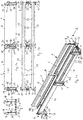
- FIGS. 1a to 1d a section of a first embodiment of a guide device is shown, which comprises two opposite, consisting of two wall elements 1, 2 guide walls.
- Wall elements 1 shown on the bottom right are followed by further wall elements 1, which are identical to the latter, and form a first section of the guide device for depositing the lower run of an energy guiding chain not shown in the drawing.
- wall elements 1 which are identical to the latter, and form a first section of the guide device for depositing the lower run of an energy guiding chain not shown in the drawing.
- FIG. 1a 2 wall elements shown above on the other, with this identical wall elements 2, which serve a second portion of the guide means for supporting and guiding the upper strand of the energy chain.
- resulting guide means is designed so that the free end of the lower run of the energy guide chain leading to a stationary connection, for example between the in FIG. 1a shown wall elements 1, and the upper strand has a relative to the guide device movable terminal.
- Both strands of the energy guiding chain are connected to each other by an arcuate portion, wherein the arcuate portion of the energy guiding chain in the process of the same moves back and forth in said sections of the guide means.
- the upper run can, depending on its length, extend cantilevered over the lower run or rest on the lower run after a certain cantilevered length. If the upper strand extends beyond the said first section, in which it is optionally supported by the lower strand, into the mentioned second section of the guide device, it is supported and guided there by guide rails 3 arranged on the inner side of the wall elements 2.
- the height of the upper side 4 of the guide rails 3 corresponds at least approximately to the height of the lower run of the energy guiding chain arranged in the named first section.
- the wall elements 1, 2 of the first and second sections are each identical to one another and molded in one piece from plastic. How out FIG. 1a It can also be seen that the wall elements 1, 2 forming the two opposite guide walls of the guide device are connected to one another at their mutually facing end sides such that their inner sides 5 have a continuous guide surface for the upper strand extending in the longitudinal direction of the wall elements 1, 2 and in said first section form the lower strand. This means that there are no free spaces between the adjacent inner sides 5 of the wall elements 1, 2 in the region of their mutually facing end faces.
- the wall elements 1, 2 have in the region of their front ends integrally formed first fastening means 6 for positive fixing to an immediately adjacent Wall element 1, 2 against separation of this and pivoting relative to this in any direction.
- the fastening means explained further below are designed such that sections of the guide device form guide components comprising two or three wall elements 1, 2, without further separate fastening means, which are safe to handle and cantilevered during transport and installation over their entire length.
- the wall elements 1, 2 used in the embodiment have a length of 0.5 m and can form a stable two or three wall elements 1, 2 comprehensive component in the interconnected state.
- the wall elements 1, 2 For attachment to a base, which can also consist of brackets, the wall elements 1, 2 in one piece on this molded second fastening means 7.
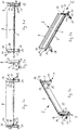
- the two wall elements 1, 2, of which the said first and second sections of the guide means are composed, are described in greater detail in FIGS FIGS. 2a to 2e or 3a to 3e shown.
- the wall elements 1, 2 have a substantially equal wall thickness over their entire height.
- the wall elements 1, 2 are bent in the region of its upper side 8 to the outside.
- the wall elements 1, 2 have flat end faces 9, 10.
- the first fastening means 6 for connecting immediately adjacent wall elements 1, 2 include projections 11, 12 which protrude in the region of the two front ends of the wall elements 1, 2 on the end faces 9, 10 and on the outer side 13 of the wall element 1, 2.
- the projections 11 at the Front side 9 are offset in height relative to the projections 12 on the end face 10 arranged so that they, as in Figure 1c shown, the outside of an immediately adjacent wall element 1, 2 overlap in the region of the front end and engage without forming a height-wise gap between each other.
- the projections 11, 12 cause an exact height alignment of the wall elements 1, 2 to each other and secure the connection of the wall elements 1, 2 against the solution in a direction transverse to its longitudinal direction.
- the first fastening means 6 for connecting immediate wall elements 1, 2 further include integrally molded on the wall elements 1, 2 molded together locking means 14, 15 in the region of the front ends of the wall elements 1, 2 a.
- the locking means 14 in the region of the end face 10 is formed as a projecting at the relevant end face 10 projection with a latching region 16.
- the locking means 15 corresponding to this latching means 14 in the region of the other end face 9 is provided with a window-like opening 17, into which the latching area 16 of the projection of an immediately adjacent wall element 1, 2 can be latched.
- the latching region 16 of the projection protrudes from the outer side 13 of the wall element 1, 2, wherein the window-like opening 17 corresponding to the latching region 16 is formed in a part 18 projecting from the outside of the wall element 1, 2.
- the latching region 16 and the window-like opening 17 having part 18 are each in front of the front sides 9 and 10 so that they are in the connected state of the immediately adjacent wall elements 1, 2 substantially symmetrically with respect to the abutting end faces 9, 10 of Wall elements 1, 2 are formed, in particular from Figure 1c evident.
- the second fastening means 7 for fastening the wall elements 1, 2 on a base are formed as fixing lugs 20, 21 extending parallel to the underside 19 of the wall elements 1, 2. These are opposite to the end faces 9 and 10 of the wall elements 1, 2 before and overlap when connected to an immediately adjacent wall element 1, 2, in particular from the FIGS. 1a and 1c evident.
- the fastening tabs extend on the outside 13 of the wall elements 1, 2 to the outside.
- a tongue and groove connection is provided for additional protection against separation and tilting of immediately adjacent wall elements.
- the groove 22 extends in one of the respective end face 9 of the wall element 1, 2 pioneering end portion of the fastening tab 21 transversely to the longitudinal direction of the wall element 1, 2, while the spring 23 in a corresponding, on the other end face 10 of the wall element 1, second extending projecting end portion in the transverse direction.
- integrally formed on the outer sides 13 of the wall elements 1, 2 webs 24, 25 are provided, which are spaced from the end faces 9 and 8 and arranged with the attachment tabs 20 and 21 form an angle.
- the fastening tabs 20, 21 opposite, on the inside 5 of the wall element 1, 2 webs 26, 27 molded, which with the webs 27 and 26 of the opposite wall element. 1 , 2 are connectable.
- the webs 26, 27 are provided at their free ends with a locking means 28, 29 which cooperates with a latching means 30 and 31 of a gutter 32 which is disposed between the webs 26 and 27 of the opposite wall elements 1, 2.
- the width of the guide means ie, the distance of the inner sides 5 of the opposite wall elements 1, 2 are adapted to the width of the leading to energy supply chain.
- the fastening straps 20, 21 have openings which, when the fastening straps of immediately adjacent wall elements 1, 2 overlap one another, serve to carry fastening screws or bolts.
- the webs 26, 27 are in connection with immediately adjacent wall elements 1, 2, as in FIG. 1b shown, against each other and form a bridge pair.
- the latching means 28, 29 of the pair of webs form a latching means which cooperates with the opposite latching means 30, 31 of a gutter 32 for producing a stable attachment.
- 1 guide rails 33 are integrally molded on the inner sides 5 of the wall elements for supporting the lower strand of the energy supply chain to be inserted.
- the guide rails extend between the webs 26 and 27 and have with them a continuous top 34 at the same level.
- attachment regions 35, 36 The end-side end regions of the wall elements 1, 2, which enclose the first fastening means 6 for positive and / or frictional attachment to an immediately adjacent wall element 1, 2, are referred to below as attachment regions 35, 36.
- the wall portions 39 and 40 of the wall elements 1 extend substantially over the entire height of the mounting portions 35 and 36, since they lead both the lower strand and the upper strand of the energy supply chain to be inserted laterally. Between these guide areas and the attachment areas 35 and 36, the wall elements 1 have convex bulges 41 for increasing the stability of the wall elements 1 against transversely acting forces on the guide device.
- the wall portions 42 of the wall elements 2 extend between the mounting portions 35 and 36 between the molded onto the inside 5 guide rail 3 and the same height level as the wall elements 1 arranged top 8.
- the space below the wall portion 42 between the mounting portions 35 and 36 is open.
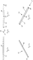
- FIGS. 4a to 4e a portion of another embodiment of a guide device is shown, which in the same place as in the FIGS. 1a to 1d shown portion is arranged in the guide device. Only the differences between the wall elements 45 used in this embodiment and the wall elements 1, 2 discussed above will be explained below. Regarding the others in the FIGS. 4a to 4e and 5a to 5e shown details of the wall elements 45 is made to the first embodiment described above.
- All wall elements 45 of the second embodiment of a guide device are identical and injection molded in one piece from plastic.
- the wall elements 45 correspond to the wall elements 1 of the first exemplary embodiment except for a device for arranging a separate guide rail 46 at different heights on the inner side 5 of the wall element 45.
- the guide rails 46 are, as in particular from the FIGS. 6a to 6e shows, in the form of an elongated, angularly shaped in cross-section element, wherein the one leg 47 is provided for attachment to the respective wall element 45 and the substantially perpendicular thereto extending second leg 48 for supporting the upper strand.
- the serving for fastening leg 47 has the wall member 45 directed toward nubs 49 in the region of its ends and in the central region, which engage positively and non-positively in corresponding with the nubs openings 50 in the wall member 45.
- a plurality of superimposed openings 50 are provided in the wall elements 45, respectively.
- Such wall elements 45 which further comprise guide rails 33 integrally formed thereon for the lower run, are used to form the above-mentioned first and second sections of the guide device, wherein the separate guide rails 46 for the upper run are fastened to the wall elements 45 only in the second section.
- FIGS. 7a to 7e In a third embodiment of a guide means wall elements 51 are used, as you in the FIGS. 7a to 7e are shown.
- wall area between the attachment areas 35 and 36 has a window-like opening 52. This extends in height with a certain distance from the integrally molded thereto guide rail 33, which is sufficient for lateral guidance of the lower strand, to about the outwardly bent portion at the top of the wall member 51st
- the wall member 51 may be used in a guide device instead of the wall member 1 of the above-described first embodiment, a guide means together with wall members 2 or wall members 45 of the second embodiment described above.
- the wall elements 51 may alternatively be used to form a guide means for the lower strand formed as an extension channel.
Description
Die Erfindung betrifft eine Führungseinrichtung für eine Leitung, insbesondere für eine Energieführungskette, wobei die Leitung derart verfahrbar ist, dass ein oberer Abschnitt derselben über einen unteren Abschnitt positionierbar ist, und beide Abschnitte durch einen bogenförmigen Abschnitt miteinander verbunden sind, wobei die Führungseinrichtung zumindest in einem Bereich seitlich gegenüberliegende Führungswände zur Führung des oberen Abschnitts und/oder des unteren Abschnitts aufweist, die aus seitlich gegenüberliegenden Wandelementen bestehen, die jeweils zwei voneinander in Längsrichtung des Wandelements wegweisende Stirnseiten, eine von dem seitlich gegenüberliegenden Wandelement wegweisende Außenseite, eine zu dem seitlich gegenüberliegenden Wandelement hinweisende Innenseite, eine Oberseite und eine Unterseite aufweisen, wobei die eine Führungswand bildenden Wandelemente im Bereich ihrer stirnseitigen Enden miteinander verbunden sind, so dass sie an ihren Innenseiten eine sich über die gesamte Führungswand erstreckende durchgehende Führungsfläche bilden, wobei die Wandelemente einstückig aus Kunststoff geformt sind, im Bereich ihrer stirnseitigen Enden einstückig angeformte erste Befestigungsmittel zur form- und/oder kraftschlüssigen Festlegung an einem unmittelbar benachbarten Wandelement gegen Trennung von diesem und Verschwenkung gegenüber diesem in jeder beliebigen Richtung aufweisen.The invention relates to a guide device for a line, in particular for a power transmission chain, wherein the line is movable such that an upper portion thereof is positioned over a lower portion, and both sections are interconnected by an arcuate portion, wherein the guide means at least in one Area laterally opposite guide walls for guiding the upper portion and / or the lower portion, which consist of laterally opposite wall elements, each two facing away from each other in the longitudinal direction of the wall element end faces, a direction away from the laterally opposite wall element outside, one to the laterally opposite wall element indicative inside, have an upper side and a lower side, wherein the wall elements forming a guide wall are connected to each other in the region of their front ends, so that they at their Inne nseiten form a over the entire guide wall extending continuous guide surface, wherein the wall elements are integrally molded plastic, in the region of their front ends integrally formed first fastening means for positive and / or non-positive fixing to an immediately adjacent wall element against separation of this and pivoting have this in any direction.
Der vorstehend genannte obere Abschnitt der Leitung, insbesondere Energieführungskette, wird auch als Obertrum und der untere Abschnitt der Leitung als Untertrum bezeichnet.The above-mentioned upper portion of the line, in particular energy chain, is also referred to as upper run and the lower portion of the line as Untertrum.
Eine Führungseinrichtung der vorstehend genannten Art ist aus der
Der vorliegenden Erfindung liegt die Aufgabe zugrunde, eine derartige Führungswände aufweisende Führungseinrichtung dahingehend zu verbessern, dass sie einfacher montiert werden kann, wobei die die Führungswände bildenden Wandelemente stabil miteinander verbunden werden können.The present invention has for its object to improve such guide walls having guide means to the effect that it can be easily mounted, wherein the guide walls forming wall elements can be stably connected to each other.
Die Aufgabe wird erfindungsgemäß durch eine Führungseinrichtung der eingangs genannten Art dadurch gelöst, dass die Wandelemente im Bereich ihrer stirnseitigen Enden zum gegenüberliegenden Wandelement hin gerichtete Stege aufweisen, die durch Zwischenschaltung eines Zwischenstegs miteinander verbindbar sind, und dass die benachbarten Stege zweier unmittelbar benachbarter Wandelemente zusammen ein Rastmittel zur Verbindung mit einem Zwischensteg bilden.The object is achieved by a guide device of the type mentioned above in that the wall elements in the region of their front ends to the opposite wall element directed webs, which are interconnected by interposition of a gutter, and that the adjacent webs of two immediately adjacent wall elements together Form latching means for connection to a gutter.
Zwecks Anpassung an die Breite einer in der Führungseinrichtung zu führenden Leitung, insbesondere einer Energieführungskette, können Zwischenstege mit unterschiedlichen Längen vorgesehen sein, die lösbar mit den an den Wandelementen angeformten Stegen verbindbar sind.In order to adapt to the width of a leading in the guide device line, in particular a power transmission chain, intermediate webs can be provided with different lengths, which are detachably connected to the integrally formed on the wall elements webs.
Die benachbarten Stege zweier unmittelbar benachbarter Wandelemente können, bevorzugt aneinander anliegend, zusammen ein Rastmittel zur Verbindung mit einem Zwischensteg bilden. Dadurch wird der Zusammenhalt unmittelbar benachbarter Wandelemente noch weiter erhöht.The adjacent webs of two immediately adjacent wall elements, preferably adjacent to each other, together form a locking means for connection to a gutter. As a result, the cohesion of immediately adjacent wall elements is further increased.
Die ersten Befestigungsmittel zur Verbindung unmittelbar benachbarter Wandelemente können insbesondere derart ausgelegt sein, dass Abschnitte der Führungseinrichtung aus mehrere Wandelemente aufweisenden Führungswänden ohne weitere (separate) Befestigungsmittel in sich stabile Bauteile bilden, die sicher beim Transport und der Montage handhabbar und über ihre gesamte Länge hinweg freitragend sind.The first attachment means for connecting immediately adjacent wall elements may in particular be designed such that portions of the guide means comprising several wall elements having guide walls without further (separate) fasteners form stable components that are safe to handle during transport and assembly and cantilevered over its entire length away are.
Die Wandelemente können z.B. eine Länge zwischen 0,5m und 1m haben. Zwei oder drei miteinander verbundene Wandelemente, die ein stabiles Bauteil bilden, haben dann eine Länge zwischen 1m und 3m.The wall elements may e.g. have a length between 0.5m and 1m. Two or three interconnected wall elements, which form a stable component, then have a length between 1m and 3m.
Die ersten Befestigungsmittel zur Verbindung benachbarter Wandelemente können weiterhin derart ausgestaltet sein, dass nur jedes zweite oder dritte Wandelement einer Führungswand der Führungseinrichtung auf einer Basis, z.B. einer Konsole bei einer Krananlage, befestigt werden muss.The first fastening means for connecting adjacent wall elements may further be configured such that only every second or third wall element of a guide wall of the guide means is mounted on a base, e.g. a console in a crane system, must be attached.
In einer bevorzugten Ausführung weisen die Wandelemente einstückig an diese angeformte zweite Befestigungsmittel zur Befestigung der Wandelemente auf einer Basis oder dergleichen auf.In a preferred embodiment, the wall elements are integrally formed on these second fastening means for fastening the wall elements on a base or the like.
Insbesondere können die Wandelemente beider Führungswände identisch zueinander ausgebildet sein.In particular, the wall elements of both guide walls can be identical to one another.
Weiterhin können die Wandelemente über ihre gesamte Höhe hinweg eine im Wesentlichen gleiche Wandstärke aufweisen.Furthermore, the wall elements over their entire height can have a substantially equal wall thickness.
Zum besseren Einlegen der Leitung, insbesondere der Energieführungskette, in die Führungseinrichtung sind die Wandelemente im Bereich ihrer Oberseite bevorzugt nach außen gebogen.For better insertion of the line, in particular the energy chain, in the guide means, the wall elements in the region of their top are preferably outward bent.
Zur Bildung der ersten Befestigungsmittel können die Wandelemente im Bereich eines ihrer beiden stirnseitigen Enden mindestens einen an der betreffenden Stirnseite vorstehenden Vorsprung und im Bereich des anderen stirnseitigen Endes eine mit dem Vorsprung korrespondierende Öffnung aufweisen, in die der Vorsprung eines unmittelbar benachbarten Wandelements einbringbar ist.To form the first fastening means, the wall elements in the region of one of its two front ends may have at least one protrusion projecting on the end face in question and an opening corresponding to the protrusion in the region of the other end face into which the protrusion of an immediately adjacent wall element can be introduced.
In einer bevorzugten Weiterbildung weisen die Wandelemente ebene Stirnseiten auf. Dabei können die Wandelemente im Bereich ihrer beiden stirnseitigen Enden an ihrer Stirnseite vorstehende Vorsprünge aufweisen, die an einem stirnseitigen Ende höhenversetzt gegenüber dem Vorsprung oder den Vorsprüngen am anderen stirnseitigen Ende so angeordnet sind, dass sie außenseitige Bereiche eines unmittelbar benachbarten Wandelements zumindest teilweise überdecken und zumindest ein Vorsprung zwischen zwei Vorsprünge ohne höhenmäßigen Zwischenraum eingreift.In a preferred embodiment, the wall elements on flat end faces. In this case, the wall elements in the region of its two front ends on its front side projecting projections which are arranged offset in height at one end face relative to the projection or the projections on the other front end so that they at least partially cover outside areas of an immediately adjacent wall element and at least a projection between two projections engages without height intermediate space.
Die Vorsprünge sind bevorzugt außenseitig an den Wandelementen angeordnet, so dass sie die Außenseite unmittelbar benachbarter Wandelemente zumindest teilweise überdecken.The projections are preferably arranged on the outside of the wall elements, so that they at least partially cover the outside of immediately adjacent wall elements.
Bei einer vorteilhaften Weiterbildung der Erfindung weisen die Wandelemente im Bereich ihrer beiden stirnseitigen Enden einstückig angeformte miteinander korrespondierende Rastmittel auf, die derart ausgebildet sind, dass sie mit dem korrespondierenden Rastmittel eines unmittelbar benachbarten Wandelements eine Rastverbindung gegen Lösen der Wandelemente von einander in deren Längsrichtung eingehen können.In an advantageous embodiment of the invention, the wall elements in the region of its two end-side ends integrally formed with each other corresponding locking means which are designed such that they can enter with the corresponding locking means of an immediately adjacent wall element a locking connection against loosening of the wall elements of each other in the longitudinal direction ,
In einer bevorzugten Ausführung ist das Rastmittel im Bereich eines der stirnseitigen Enden als ein an der betreffenden Stirnseite vorstehender Vorsprung mit einem Rastbereich ausgebildet und das korrespondierende Rastmittel im Bereich des anderen stirnseitigen Endes mit einer Öffnung versehen, in die der Rastbereich des Vorsprungs eines unmittelbar benachbarten Wandelementes einrastbar ist.In a preferred embodiment, the latching means is formed in the region of one of the front ends as a projecting projection on the relevant end face with a latching area and the corresponding latching means in the region of the other end face provided with an opening in the the latching region of the projection of an immediately adjacent wall element can be latched.
Der Rastbereich des Vorsprungs kann von der Außenseite des Wandelements vorstehen, wobei die mit dem Rastbereich korrespondierende Öffnung in einem von der Außenseite des Wandelements vorstehenden Teil ausgebildet ist.The latching region of the projection may project from the outside of the wall element, wherein the opening corresponding to the latching region is formed in a part projecting from the outside of the wall element.
In einer bevorzugten Ausbildung ist die Öffnung fensterartig in diesem Teil ausgebildet, wobei der Rastbereich mit der fensterartigen Öffnung korrespondiert.In a preferred embodiment, the opening is window-like formed in this part, wherein the latching area corresponds to the window-like opening.
Der Rastbereich und der die Öffnung aufweisende Teil können jeweils zur Hälfte an der betreffenden Stirnseite vorstehen. Insbesondere können der Rastbereich und der die Öffnung aufweisende Teil im verbundenen Zustand der unmittelbar benachbarten Wandelemente im Wesentlich symmetrisch bezüglich der aneinander anliegenden Stirnseiten der Wandelemente ausgebildet sein.The latching region and the part having the opening can protrude in each case half at the respective end face. In particular, the latching region and the part having the opening in the connected state of the immediately adjacent wall elements may be formed substantially symmetrically with respect to the abutting end faces of the wall elements.
Die zweiten Befestigungsmittel zur Befestigung der Wandelemente auf einer Basis oder dergleichen sind bevorzugt als sich parallel zur Unterseite der Wandelemente erstreckende Befestigungslaschen ausgebildet, die gegenüber den Stirnseiten der Wandelemente vorstehen und sich bei Verbindung eines Wandelements mit einem unmittelbar benachbarten Wandelement überlappen.The second fastening means for fastening the wall elements on a base or the like are preferably designed as attachment tabs extending parallel to the underside of the wall elements, which project with respect to the end faces of the wall elements and overlap with an immediately adjacent wall element when a wall element is connected.
Die Befestigungslaschen können sich insbesondere an der Außenseite der Wandelemente nach außen erstrecken. Alternativ kann vorgesehen sein, dass sie sich an der Innenseite der Wandelemente in Richtung auf das jeweils gegenüberliegende Wandelement erstrecken.The fastening straps can extend outwards, in particular on the outside of the wall elements. Alternatively, it can be provided that they extend on the inside of the wall elements in the direction of the respective opposite wall element.
In den Überlappungsbereichen der Befestigungslaschen kann zur zusätzlichen Sicherung gegen Trennen der unmittelbar benachbarten Wandelemente in deren Längsrichtung eine Nut-Feder-Verbindung vorgesehen sein. Die Nut erstreckt sich vorzugsweise in einem von der betreffenden Stirnseite des Wandelements wegweisenden Endabschnitt der einen Befestigungslasche quer zur Längsrichtung des Wandelements, während die Feder sich in einem entsprechenden, an der anderen Stirnseite des Wandelements vorstehenden Endabschnitt in Querrichtung erstreckt.In the overlapping areas of the fastening tabs can for additional safeguard against separation of the immediately adjacent wall elements in the longitudinal direction of a tongue and groove connection may be provided. The groove preferably extends in a direction away from the respective end face of the wall member end portion of a fastening strap transverse to the longitudinal direction of the wall member, while the spring extends in a corresponding, on the other end side of the wall member projecting end portion in the transverse direction.
Weiterhin können Führungsschienen an den Innenseiten mindestens eines Paars gegenüberliegender Wandelemente zur Abstützung des Untertrums einer in der Führungseinrichtung verfahrbaren Leitung, insbesondere einer Energieführungskette, einstückig angeformt sein.Furthermore, guide rails on the inner sides of at least one pair of opposing wall elements for supporting the lower run of a movable in the guide device line, in particular a power transmission chain, in one piece be formed.
Bei einer Anordnung der Leitung, insbesondere einer Energieführungskette, bei der das freie Ende des Untertrums einen gegenüber der Führungseinrichtung stationären Anschluss und das freie Ende des Obertrums einen gegenüber der Führungseinrichtung beweglichen Anschluss aufweist, erstrecken sich die Wandelemente mit den daran angeformten Führungsschienen für das Untertrum vom stationären Anschluss aus etwa über die maximale Länge des Untertrums beim Verfahren der Leitung. In diesem ersten Abschnitt kann sich das Obertrum zum Beispiel freitragend über dem Untertrum erstrecken oder sich nach einer bestimmten freitragenden Länge auf dem Untertrum ablegen. Bei längeren Verfahrwegen ist eine Abstützung des Obertrums außerhalb des genannten ersten Abschnitts der Führungseinrichtung, d.h. jenseits des stationären Anschlusses des Untertrums, in einem zweiten Abschnitt der Führungseinrichtung vorgesehen. Der zweite Abschnitt erstreckt sich vom stationären Anschlusspunkt etwa über die maximale Länge des Obertrums beim Verfahren der Leitung, insbesondere einer Energieführungskette.In an arrangement of the line, in particular a power transmission chain, in which the free end of the lower strand has a relative to the guide means stationary connection and the free end of the upper run a relative to the guide device movable terminal, extend the wall elements with the molded thereon guide rails for the lower run of stationary connection from about the maximum length of the lower strand in the process of the line. For example, in this first section, the upper strand can extend cantilevered over the lower strand or settle on the lower strand after a certain cantilevered length. For longer travel distances, support of the upper strand outside of said first portion of the guide means, i. beyond the stationary connection of the lower run, provided in a second section of the guide device. The second section extends from the stationary connection point approximately over the maximum length of the upper strand during the process of the line, in particular an energy transmission chain.
In diesem zweiten Abschnitt kann die Führungseinrichtung Wandelemente aufweisen, an deren Innenseiten Führungsschienen für das Obertrum der Leitung, insbesondere einer Energieführungskette, einstückig angeformt sind.In this second section, the guide device may comprise wall elements, on whose insides guide rails for the upper run of the line, in particular an energy guide chain, are integrally formed.
Der Wandbereich dieser Wandelemente kann zwischen den ersten Befestigungsmitteln zur Verbindung unmittelbar benachbarter Wandelemente und gegebenenfalls zweiten Befestigungsmitteln zur Befestigung der Wandelemente auf einer Basis oder dergleichen unterhalb der Führungsschienen für das Obertrum durchbrochen sein.The wall portion of these wall elements can be broken between the first attachment means for connecting immediately adjacent wall elements and optionally second attachment means for fixing the wall elements on a base or the like below the upper run guide rails.
Die einstückigen Wandelemente der genannten Abschnitte sind bevorzugt jeweils identisch ausgebildet.The one-piece wall elements of said sections are preferably formed identically.
Alternativ zu einstückig angeformten Führungsschienen für das Obertrum können in dem genannten zweiten Abschnitt der Führungseinrichtung die gegenüberliegenden Wandelemente an ihren Innenseiten separate Führungsschienen für das Obertrum aufweisen, die vorzugsweise in unterschiedlichen Höhen an den Wandelementen form- und/oder kraftschlüssig befestigbar sind.As an alternative to integrally formed guide rails for the upper run, the opposite wall elements can have separate guide rails for the upper run in their inner sides in the second section of the guide device, which can preferably be fastened in different heights to the wall elements in a positive and / or non-positive manner.
Die Führungsschienen können in Form eines langgestreckten, im Querschnitt winkelförmigen Elements ausgeführt sein, wobei der eine Schenkel zur Befestigung an dem betreffenden Wandelement und der im Wesentlichen senkrecht dazu verlaufende zweite Schenkel zur Auflage des Obertrums vorgesehen sind. Der zur Befestigung dienende Schenkel kann zum Wandelement hin gerichtete Noppen im Bereich seiner Enden und vorzugsweise auch im mittleren Bereich aufweisen, die in mit den Noppen korrespondierende Öffnungen in den Wandelementen form- und/oder kraftschlüssig eingreifen.The guide rails can be designed in the form of an elongated, angularly cross-sectional element, wherein the one leg for attachment to the respective wall element and the substantially perpendicular thereto extending second leg are provided for supporting the upper strand. The leg serving for fastening may have knobs directed towards the wall element in the region of its ends and preferably also in the middle region, which engage positively and / or non-positively in openings in the wall elements which correspond to the knobs.
Um eine Höhenverstellung der separaten Führungsschienen für das Obertrum an den Wandelementen zu ermöglichen, können jeweils mehrere übereinander angeordnete Öffnungen in den Wandelementen vorgesehen sein.In order to enable a height adjustment of the separate guide rails for the upper run on the wall elements, a plurality of superposed openings may be provided in the wall elements in each case.
Derartige Wandelemente mit daran einstückig angeformten Führungsschienen für das Untertrum können zur Bildung der genannten ersten und zweiten Abschnitte der Führungseinrichtung verwendet werden, wobei nur im zweiten Abschnitt die separaten Führungsschienen für das Obertrum an den Wandelementen befestigt sind. Alle für die Führungseinrichtung verwendeten Wandelemente können bei dieser Ausführung identisch sein.Such wall elements with integrally formed guide rails for the lower run can be used to form said first and second sections of the guide means, wherein only in the second section the separate guide rails for the upper strand are fixed to the wall elements. All wall elements used for the guide device may be identical in this embodiment.
Bevorzugte Ausführungsbeispiele der vorliegenden Erfindung werden im Folgenden anhand der Zeichnung näher beschrieben.
- Figur 1a
- eine perspektivische Ansicht eines aus jeweils zwei unmittelbar benachbarten Wandelementen bestehenden Abschnitts einer Führungseinrichtung,
- Figur 1b
- eine Draufsicht auf den in
Figur 1a dargestellten Abschnitt, - Figur 1c
- eine seitliche, auf die Außenseite des in
Figur 1a dargestellten Abschnitts gerichtete Ansicht, - Figur 1d
- eine stirnseitige Ansicht des in
Figur 1a dargestellten Abschnitts in Richtung des Pfeils A, - Figur 2a
- eine perspektivische, auf die Innenseite eines der in
Figur 1a rechts gezeigten Wandelemente gerichtete Ansicht, - Figur 2b
- eine perspektivische, auf die Außenseite des Wandelements gerichtete Ansicht,
- Figur 2c
- eine seitliche, auf die Außenseite gerichtete Ansicht des Wandelements,
- Figur 2d
- eine seitliche, auf die Innenseite des Wandelements gerichtete Ansicht,
- Figur 2e
- eine stirnseitige Ansicht des Wandelements in Richtung des Pfeils B in
Figur 2a , - Figur 3a
- eine perspektivische, auf die Außenseite einer der in
Figur 1a links gezeigten Wandelemente gerichtete Ansicht, - Figur 3b
- eine perspektivische, auf die Innenseite des Wandelements gerichtete Ansicht,
- Figur 3c
- eine seitliche, auf die Außenseite des Wandelements gerichtete Ansicht,
- Figur 3d
- eine seitliche, auf die Innenseite des Wandelements gerichtete Ansicht,
- Figur 3e
- eine stirnseitige Ansicht des Wandelements in Richtung des Pfeils C in
Figur 3a , - Figur 4a
- eine perspektivische Ansicht eines zweiten Ausführungsbeispiels für einen aus jeweils zwei Wandelementen bestehenden Abschnitt einer Führungseinrichtung,
- Figur 4b
- eine Draufsicht auf den in
Figur 4a dargestellten Abschnitt, - Figur 4c
- eine seitliche, auf die Außenseite des in
Figur 4a dargestellten Abschnitts gerichteten Ansicht, - Figur 4d
- eine vergrößerte Ansicht des Bereichs A in
Figur 4c , - Figur 4e
- eine stirnseitige Ansicht des in
Figur 4a dargestellten Abschnitts in Richtung des Pfeils D, Figur 5a- eine perspektivische, auf die Außenseite eines der in
Fig. 4a gezeigten Wandelemente gerichtete Ansicht, - Figur 5b
- eine perspektivisch, auf die Innenseite des Wandelements gerichtete Ansicht,
- Figur 5c
- eine seitliche, auf die Außenseite des Wandelements gerichtete Ansicht,
- Figur 5d
- eine seitliche, auf die Innenseite des Wandelements gerichtete Ansicht,
- Figur 5e
- eine stirnseitige Ansicht des Wandelements in Richtung des Pfeils E in
Figur 5b , - Figur 6a
- eine perspektivische, auf die Innenseite der in
Figur 4a dargestellten Führungsschiene gerichtete Ansicht, - Figur 6b
- eine perspektivische, auf die Außenseite der Führungsschiene gerichtete Ansicht,
- Figur 6c
- seitliche, auf die Innenseite der Führungsschiene gerichtete Ansicht,
Figur 6d- seitliche, auf die Außenseite der Führungsschiene gerichtete Ansicht,
- Figur 6e
- eine perspektivische Ansicht der Führungsschiene in Richtung des Pfeils F in
Figur 6b , - Figur 7a
- eine perspektivische, auf die Außenseite einer weiteren Ausführung eines Wandelements gerichtete Ansicht,
- Figur 7b
- eine perspektivische, auf die Innenseite des Wandelements gerichtete Ansicht,
- Figur 7c
- eine seitliche, auf die Außenseite des Wandelements gerichtete Ansicht,
- Figur 7d
- eine seitliche, auf die Innenseite des Wandelements gerichtete Ansicht und
- Figur 7e
- eine stirnseitige Ansicht des Wandelements in Richtung des Pfeils G in
Figur 7b .
- FIG. 1a
- 3 a perspective view of a section of a guide device consisting of two directly adjacent wall elements,
- FIG. 1b
- a top view of the in
FIG. 1a represented section, - Figure 1c
- a lateral, on the outside of the in
FIG. 1a shown section directed view, - Figure 1d
- a frontal view of the in
FIG. 1a shown portion in the direction of arrow A, - FIG. 2a
- a perspective, on the inside of one of the
FIG. 1a right side wall elements directed view, - FIG. 2b
- a perspective view directed towards the outside of the wall element,
- Figure 2c
- a lateral, outwardly facing view of the wall element,
- Figure 2d
- a lateral view directed at the inside of the wall element,
- FIG. 2e
- an end view of the wall element in the direction of arrow B in
FIG. 2a . - FIG. 3a
- a perspective, on the outside of one of the in
FIG. 1a left side wall elements, - FIG. 3b
- a perspective view directed at the inside of the wall element,
- Figure 3c
- a lateral view directed towards the outside of the wall element,
- 3d figure
- a lateral view directed at the inside of the wall element,
- FIG. 3e
- an end view of the wall element in the direction of arrow C in
FIG. 3a . - FIG. 4a
- 3 is a perspective view of a second exemplary embodiment of a section of a guide device consisting of two wall elements each,
- FIG. 4b
- a top view of the in
FIG. 4a represented section, - Figure 4c
- a lateral, on the outside of the in
FIG. 4a shown section directed view, - FIG. 4d
- an enlarged view of the area A in
Figure 4c . - Figure 4e
- a frontal view of the in
FIG. 4a shown portion in the direction of arrow D, - FIG. 5a
- a perspective, on the outside of one of the
Fig. 4a shown wall elements directed view, - FIG. 5b
- a perspective, directed to the inside of the wall element view,
- FIG. 5c
- a lateral view directed towards the outside of the wall element,
- FIG. 5d
- a lateral view directed at the inside of the wall element,
- FIG. 5e
- an end view of the wall element in the direction of arrow E in
FIG. 5b . - FIG. 6a
- a perspective, on the inside of the in
FIG. 4a illustrated guide rail directed view, - FIG. 6b
- a perspective view directed towards the outside of the guide rail,
- FIG. 6c
- lateral view directed towards the inside of the guide rail,
- FIG. 6d
- lateral view directed towards the outside of the guide rail,
- FIG. 6e
- a perspective view of the guide rail in the direction of the arrow F in
FIG. 6b . - Figure 7a
- a perspective view, directed to the outside of a further embodiment of a wall element,
- FIG. 7b
- a perspective view directed at the inside of the wall element,
- FIG. 7c
- a lateral view directed towards the outside of the wall element,
- FIG. 7d
- a lateral, on the inside of the wall element directed view and
- Figure 7e
- an end view of the wall element in the direction of arrow G in
FIG. 7b ,
In den
In dem genannten ersten Abschnitt kann sich das Obertrum je nach dessen Länge freitragend über dem Untertrum erstrecken oder sich nach einer bestimmten freitragenden Länge auf dem Untertrum ablegen. Erstreckt sich das Obertrum über den genannten ersten Abschnitt, in dem es gegebenenfalls durch das Untertrum abgestützt wird, in den genannten zweiten Abschnitt der Führungseinrichtung hinein, wird es dort durch an der Innenseite der Wandelemente 2 angeordnete Führungsschienen 3 abgestützt und geführt. Die Höhe der Oberseite 4 der Führungsschienen 3 entspricht zumindest annähernd der Höhe des im genannten ersten Abschnitt angeordneten Untertrums der Energieführungskette.In the above-mentioned first section, the upper run can, depending on its length, extend cantilevered over the lower run or rest on the lower run after a certain cantilevered length. If the upper strand extends beyond the said first section, in which it is optionally supported by the lower strand, into the mentioned second section of the guide device, it is supported and guided there by
Die Wandelemente 1, 2 des ersten bzw. zweiten Abschnitts sind jeweils mit einander identisch und einstückig aus Kunststoff gespritzt. Wie aus
Die Wandelemente 1, 2 weisen im Bereich ihrer stirnseitigen Enden einstückig angeformte erste Befestigungsmittel 6 zur formschlüssigen Festlegung an einem unmittelbar benachbarten Wandelement 1, 2 gegen Trennung von diesem und Verschwenkung gegenüber diesem in jeder beliebigen Richtung auf. Die unten weiter erläuterten Befestigungsmittel sind so ausgelegt, dass Abschnitte der Führungseinrichtung aus zwei oder drei Wandelemente 1,2 aufweisenden Führungswänden ohne weitere separate Befestigungsmittel in sich stabile Bauteile bilden, die beim Transport und der Montage sicher handhabbar und über ihre gesamte Länge hinweg freitragend sind. Die im Ausführungsbeispiel verwendeten Wandelemente 1, 2 haben eine Länge von 0,5m und können im miteinander verbundenen Zustand ein stabiles zwei oder drei Wandelemente 1, 2 umfassendes Bauteil bilden.The
Für ein solches Bauteil kann es ausreichend sein, nur jedes zweite bzw. dritte Wandelement 1, 2 auf einer Basis, zum Beispiel einer Konsole bei einer Krananlage, zu befestigen.For such a component it may be sufficient to fasten only every second or
Zur Befestigung auf einer Basis, die auch aus Konsolen bestehen kann, weisen die Wandelemente 1, 2 einstückig an diese angespritzte zweite Befestigungsmittel 7 auf.For attachment to a base, which can also consist of brackets, the
Die beiden Wandelemente 1, 2, aus denen die genannten ersten und zweiten Abschnitte der Führungseinrichtung zusammengesetzt sind, werden genauer in den
Die Wandelemente 1, 2 weisen ebene Stirnseiten 9, 10 auf. Die ersten Befestigungsmittel 6 zur Verbindung unmittelbar benachbarter Wandelemente 1, 2 schließen Vorsprünge 11, 12 ein, die im Bereich der beiden stirnseitigen Enden der Wandelemente 1, 2 an den Stirnseiten 9, 10 und an der Außenseite 13 des Wandelements 1, 2 vorstehen. Die Vorsprünge 11 an der Stirnseite 9 sind höhenversetzt gegenüber den Vorsprüngen 12 an der Stirnseite 10 so angeordnet, dass sie, wie in
Die ersten Befestigungsmittel 6 zur Verbindung unmittelbarer Wandelemente 1, 2 schließen weiterhin einstückig an die Wandelemente 1, 2 angespritzte miteinander korrespondierende Rastmittel 14, 15 im Bereich der stirnseitigen Enden der Wandelemente 1, 2 ein. Das Rastmittel 14 im Bereich der Stirnseite 10 ist als ein an der betreffenden Stirnseite 10 vorstehender Vorsprung mit einem Rastbereich 16 ausgebildet. Das mit diesem Rastmittel 14 korrespondierende Rastmittel 15 im Bereich der anderen Stirnseite 9 ist mit einer fensterartigen Öffnung 17 versehen, in die der Rastbereich 16 des Vorsprungs eines unmittelbar benachbarten Wandelements 1, 2 einrastbar ist. Der Rastbereich 16 des Vorsprungs steht von der Außenseite 13 des Wandelements 1, 2 vor, wobei die mit dem Rastbereich 16 korrespondierende fensterartige Öffnung 17 in einem von der Außenseite des Wandelements 1, 2 vorstehenden Teil 18 ausgebildet ist.The first fastening means 6 for connecting
Der Rastbereich 16 und der die fensterartige Öffnung 17 aufweisende Teil 18 stehen jeweils zur Hälfte an den Stirnseiten 9 bzw. 10 vor, so dass sie im verbundenen Zustand der unmittelbar benachbarten Wandelemente 1, 2 im Wesentlichen symmetrisch bezüglich der einander anliegenden Stirnseiten 9, 10 der Wandelemente 1, 2 ausgebildet sind, wie insbesondere aus
Die zweiten Befestigungsmittel 7 zur Befestigung der Wandelemente 1, 2 auf einer Basis sind als sich parallel zur Unterseite 19 der Wandelemente 1, 2 erstreckende Befestigungslaschen 20, 21 ausgebildet. Diese stehen gegenüber den Stirnseiten 9 bzw. 10 der Wandelemente 1, 2 vor und überlappen sich bei Verbindung mit einem unmittelbar benachbarten Wandelement 1, 2, wie insbesondere aus den
In den Überlappungsbereichen der Befestigungslaschen 20, 21 ist zur zusätzlichen Sicherung gegen Trennen und Verkippen unmittelbar benachbarter Wandelemente eine Nut-Federverbindung vorgesehen. Die Nut 22 erstreckt sich in einem von der betreffenden Stirnseite 9 des Wandelements 1, 2 wegweisenden Endabschnitt der Befestigungslasche 21 quer zur Längsrichtung des Wandelements 1, 2, während sich die Feder 23 in einem entsprechenden, an der anderen Stirnseite 10 des Wandelements 1, 2 vorstehenden Endabschnitt in Querrichtung erstreckt.In the overlapping areas of the
Weiterhin sind im Bereich der stirnseitigen Enden der Wandelemente 1, 2 zur Oberseite 8 derselben verlaufende, einstückig an den Außenseiten 13 der Wandelemente 1, 2 angeformte Stege 24, 25 vorgesehen, die beabstandet von den Stirnseiten 9 bzw. 8 angeordnet sind und mit den Befestigungslaschen 20 bzw. 21 einen Winkel bilden.Furthermore, in the region of the front ends of the
Zur Befestigung der Wandelemente 1, 2 mit ihren gegenüberliegenden Wandelementen 1, 2 sind, den Befestigungslaschen 20, 21 gegenüberliegend, an der Innenseite 5 des Wandelements 1, 2 Stege 26, 27 angespritzt, die mit den Stegen 27 bzw. 26 des gegenüberliegenden Wandelements 1, 2 verbindbar sind. Die Stege 26, 27 sind an ihren freien Enden mit einem Rastmittel 28, 29 versehen, das mit einem Rastmittel 30 bzw. 31 eines Zwischenstegs 32 zusammenwirkt, der zwischen den Stegen 26 und 27 der gegenüberliegenden Wandelemente 1, 2 angeordnet ist. Mit Hilfe von Zwischenstegen 32 unterschiedlicher Länge kann die Breite der Führungseinrichtung, d.h. der Abstand der Innenseiten 5 der gegenüberliegenden Wandelemente 1, 2 an die Breite der zu führenden Energieführungskette angepasst werden.For fastening the
Die Befestigungslaschen 20, 21 weisen Öffnungen auf, die bei Überlappen der Befestigungslaschen unmittelbar benachbarter Wandelemente 1, 2 zueinander fluchten und zur Durchführung von Befestigungsschrauben oder -bolzen dienen.The fastening straps 20, 21 have openings which, when the fastening straps of immediately
Die Stege 26, 27 liegen bei Verbindung unmittelbar benachbarter Wandelemente 1, 2, wie in
Wie insbesondere aus den
Die stirnseitigen Endbereiche der Wandelemente 1, 2, die die ersten Befestigungsmittel 6 zur form- und/oder kraftschlüssigen Festlegung an einem unmittelbar benachbarten Wandelement 1, 2 einschließen, werden im Folgenden als Befestigungsbereiche 35, 36 bezeichnet. Sie können die zweiten Befestigungsmittel 7 zur Befestigung des Wandelements 1, 2 auf einer Basis mit einschließen. In den betrachteten Ausführungsbeispielen schließen sich die von den Stegen 24 und 25 zu den Stirnseiten 9 bzw. 10 erstreckenden Wandbereiche 37, 38 und die an deren Unterseite einstückig angespritzten Befestigungslaschen 20 bzw. 21 mit ein.The end-side end regions of the
Die Wandbereiche 39 und 40 der Wandelemente 1 erstrecken sich im Wesentlichen über die gesamte Höhe der Befestigungsbereiche 35 und 36, da sie sowohl das Untertrum als auch das Obertrum der einzulegenden Energieführungskette seitlich führen. Zwischen diesen Führungsbereichen und den Befestigungsbereichen 35 und 36 weisen die Wandelemente 1 nach außen gewölbte Ausbuchtungen 41 zur Erhöhung der Stabilität der Wandelemente 1 gegen in Querrichtung wirkenden Kräften auf die Führungseinrichtung auf.The wall portions 39 and 40 of the
Wie aus den
Wie insbesondere aus den
In den
Alle Wandelemente 45 des zweiten Ausführungsbeispiels einer Führungseinrichtung sind identisch ausgebildet und einstückig aus Kunststoff gespritzt. Die Wandelemente 45 entsprechen den Wandelementen 1 des ersten Ausführungsbeispiels bis auf eine Vorrichtung zur Anordnung einer separaten Führungsschiene 46 in unterschiedlichen Höhen an der Innenseite 5 des Wandelements 45.All
Die Führungsschienen 46 sind, wie insbesondere aus den
Um eine Höhenverstellung der separaten Führungsschienen 46 für das Obertrum an den Wandelementen 45 zu ermöglichen, sind jeweils mehrere übereinander angeordnete Öffnungen 50 in den Wandelementen 45 vorgesehen.In order to allow a height adjustment of the
Derartige Wandelemente 45, die weiterhin daran einstückig angeformte Führungsschienen 33 für das Untertrum aufweisen, werden zur Bildung der oben genannten ersten und zweiten Abschnitte der Führungseinrichtung verwendet, wobei nur im zweiten Abschnitt die separaten Führungsschienen 46 für das Obertrum an den Wandelementen 45 befestigt sind.
Bei einem dritten Ausführungsbeispiel einer Führungseinrichtung werden Wandelemente 51 verwendet, wie Sie in den
Der einzige Unterschied gegenüber den in den
Das Wandelement 51 kann anstelle des Wandelements 1 des oben beschriebenen ersten Ausführungsbeispiels eine Führungseinrichtung zusammen mit Wandelementen 2 oder Wandelementen 45 des oben beschriebenen zweiten Ausführungsbeispiels in einer Führungseinrichtung verwendet werden. Die Wandelemente 51 können alternativ zur Bildung einer als Ablegerinne ausgebildeten Führungseinrichtung für das Untertrum verwendet werden.The
- 11
- Wandelementwall element
- 22
- Wandelementwall element
- 33
- Führungsschieneguide rail
- 44
- Oberseitetop
- 55
- Innenseiteinside
- 66
- erstes Befestigungsmittelfirst attachment means
- 77
- zweites Befestigungsmittelsecond fastening means
- 88th
- Oberseitetop
- 99
- Stirnseitefront
- 1010
- Stirnseitefront
- 1111
- Vorsprunghead Start
- 1212
- Vorsprunghead Start
- 1313
- Außenseiteoutside
- 1414
- Rastmittellatching means
- 1515
- Rastmittellatching means
- 1616
- RastbereichRest area
- 1717
- Öffnungopening
- 1818
- Teilpart
- 1919
- Unterseitebottom
- 2020
- Befestigungslaschemounting tab
- 2121
- Befestigungslaschemounting tab
- 2222
- Nutgroove
- 2323
- Federfeather
- 2424
- Stegweb
- 2525
- Stegweb
- 2626
- Stegweb
- 2727
- Stegweb
- 2828
- Rastmittellatching means
- 2929
- Rastmittellatching means
- 3030
- Rastmittellatching means
- 3131
- Rastmittellatching means
- 3232
- Zwischensteggutter
- 3333
- Führungschieneguide rail
- 3434
- Oberseitetop
- 3535
- Befestigungsbereichfastening area
- 3636
- Befestigungsbereichfastening area
- 3737
- Wandbereichwall area
- 3838
- Wandbereichwall area
- 3939
- Wandbereichwall area
- 4040
- Wandbereichwall area
- 4141
- Ausbuchtungbulge
- 4242
- Wandbereichwall area
- 4343
- Vorsprunghead Start
- 4444
- Nutgroove
- 4545
- Wandelementwall element
- 4646
- Führungsschieneguide rail
- 4747
- Schenkelleg
- 4848
- Schenkelleg
- 4949
- Noppenburl
- 5050
- Öffnungopening
- 5151
- Wandelementwall element
- 5252
- Öffnungopening
Claims (15)
- A guide device for a line, in particular for an energy guiding chain, wherein the line is displaceable in such a way that an upper portion thereof can be positioned over a lower portion, and both portions are connected together by an arcuate portion, wherein the guide device has guide walls which are disposed in laterally opposite relationship at least in one region for guiding the upper portion and/or the lower portion, which comprise laterally mutually opposite wall elements (1, 2, 45, 51) which respectively have two end faces (9, 10) facing away from each other in the longitudinal direction of the wall element (1, 2, 45, 51), an outside (13) facing away from the laterally opposite wall element (1, 2, 45, 51), an inside (5) facing towards the laterally opposite wall element (1, 2, 45, 51), a top side (8) and an underside (19), wherein the wall elements (1, 2, 45, 51) forming a guide wall are connected together in the region of their front-side ends so that at their insides (5) they form a continuous guide surface extending over the entire guide wall, wherein the wall elements (1, 2, 45, 51) are formed in one piece from plastic, and have first fixing means (6) formed in one piece thereon in the region of their front-side ends for positively locking and/or force-locking fixing to an immediately adjacent wall element (1, 2, 45, 51) against separation from same and pivotal movement with respect thereto in any direction, characterised in that the wall elements (1, 2, 45, 51) have limbs (26, 27) which are directed in the region of their front-side ends towards the oppositely disposed wall element (1, 2, 45, 51) and which can be connected together by the interposition of an intermediate limb (32), and that the adjacent limbs (26, 27) of two immediately adjacent wall elements (1, 2, 45, 51) together form a latching means for connection to an intermediate limb (32).
- A guide device as set forth in claim 1 characterised in that the wall elements (1, 2, 45, 51) have second fixing means formed in one piece thereon for fixing the wall elements (1, 2, 45, 51) on a base or the like.
- A guide device as set forth in claim 1 or claim 2 characterised in that the wall elements of both guide walls are of a mutually identical configuration.
- A guide device as set forth in one of claims 1 through 3 characterised in that the wall elements (1, 2, 45, 51) are of a substantially identical wall thickness over their entire height.
- A guide device as set forth in one of claims 1 through 4 characterised in that the wall elements (1, 2, 45, 51) have flat end faces (9, 10).
- A guide device as set forth in claim 5 characterised in that in the region of their front-side ends at their end face (9, 10) the wall elements (1, 2, 45, 51) have projecting projections (11, 12) which at a front-side end are arranged in height-displaced relationship with respect to the projection or the projections (11 or 12) at the other front-side end in such a way that they at least partially cover outside regions of an immediately adjacent wall element (1, 2, 45, 51) and at least one projection (11) engages between two projections (12) without an intermediate space in respect of height.
- A guide device as set forth in one of claims 1 through 6 characterised in that the wall elements (1, 2, 45, 51) have mutually corresponding latching means (14, 15) integrally formed thereon in the region of their two front-side ends, which latching means are such that they form a latching connection to prevent release of the wall elements (1, 2, 45, 51) from each other in the longitudinal direction thereof with the corresponding latching means (15, 14) of an immediately adjacent wall element (1, 2, 45, 51).
- A guide device as set forth in claim 10 characterised in that in the region of one of the firont-side ends the latching means (14) is in the form of a projection projecting at the end face (10) in question with a latching region (16) and in the region of the other front-side end the corresponding latching means (15) is provided with an opening (17) into which the latching region (16) of the projection of an immediately adjacent wall element (1, 2, 45, 51) is latchable.
- A guide device as set forth in claim 8 characterised in that the latching region (16) of the projection projects from the outside (13) of the wall element (1, 2, 45, 51), wherein the opening (17) corresponding to the latching region (16) is provided in a part (18) projecting from the outside (13) of the wall element (1, 2, 45, 51).
- A guide device as set forth in one of claims 2 through 9 characterised in that the second fixing means (7) for fixing the wall elements (1, 2, 45, 51) on a base or the like are in the form of fixing lugs (20, 21) which extend parallel to the underside (19) of the wall elements (1, 2, 45, 51) and which project with respect to the end faces (9, 10) of the wall elements (1, 2, 45, 51) and which overlap upon connection of a wall element (1, 2, 45, 51) to an immediately adjacent wall element (1, 2, 45, 51).
- A guide device as set forth in claim 10 characterised in that the fixing lugs (20, 21) extend outwardly at the outside (12) of the wall elements (1, 2, 45, 51).
- A guide device as set forth in claim 11 characterised in that a tongue-and-groove connection is provided in the overlap regions of the fixing lugs (20, 21).
- A guide device as set forth in one of claims 10 through 12 characterised in that there are provided limbs (24, 25) which extend in the region of the front-side ends of the wall elements (1, 2, 45, 51) to the top side (8) thereof and which are formed in one piece at the outsides (13) of the wall elements (1, 2, 45, 51) and which are arranged spaced from the end faces (9, 10) and form an angle with the fixing lugs (20, 21).
- A guide device as set forth in one of claims 1 through 13 characterised in that guide rails (33) are formed (in one piece) at the insides (5) of at least one pair of opposite wall elements, for supporting the lower run of a line displaceable in the guide device, in particular an energy guiding chain.
- A guide device as set forth in one of claims 1 through 14 characterised in that guide rails (33) are formed in one piece at the insides (5) of at least one pair of opposite wall elements (1, 2, 45, 51), for supporting the upper run of a line displaceable in the guide device, in particular an energy guiding chain.
Priority Applications (1)
| Application Number | Priority Date | Filing Date | Title |
|---|---|---|---|
| PL15736421T PL3175523T3 (en) | 2014-07-31 | 2015-07-01 | Guide device |
Applications Claiming Priority (2)
| Application Number | Priority Date | Filing Date | Title |
|---|---|---|---|
| DE202014103562.1U DE202014103562U1 (en) | 2014-07-31 | 2014-07-31 | guide means |
| PCT/EP2015/065000 WO2016015942A1 (en) | 2014-07-31 | 2015-07-01 | Guide device |
Publications (2)
| Publication Number | Publication Date |
|---|---|
| EP3175523A1 EP3175523A1 (en) | 2017-06-07 |
| EP3175523B1 true EP3175523B1 (en) | 2018-05-02 |
Family
ID=51629329
Family Applications (1)
| Application Number | Title | Priority Date | Filing Date |
|---|---|---|---|
| EP15736421.7A Active EP3175523B1 (en) | 2014-07-31 | 2015-07-01 | Guide device |
Country Status (9)
| Country | Link |
|---|---|
| US (1) | US10693285B2 (en) |
| EP (1) | EP3175523B1 (en) |
| JP (1) | JP6543694B2 (en) |
| KR (1) | KR101962549B1 (en) |
| CN (1) | CN107005036B (en) |
| CA (1) | CA2956720C (en) |
| DE (1) | DE202014103562U1 (en) |
| PL (1) | PL3175523T3 (en) |
| WO (1) | WO2016015942A1 (en) |
Families Citing this family (8)
| Publication number | Priority date | Publication date | Assignee | Title |
|---|---|---|---|---|
| TWI769307B (en) * | 2017-09-11 | 2022-07-01 | 麥基洗德 法蘭斯捷尼 | Constructive arrangement applied to busbar |
| DE202017105927U1 (en) | 2017-09-28 | 2019-01-08 | Igus Gmbh | guide means |
| DE202018101686U1 (en) * | 2018-03-26 | 2018-04-09 | Igus Gmbh | Energy guiding chain and divider for this purpose |
| CA3049381A1 (en) * | 2018-07-13 | 2020-01-13 | Eaton Intelligent Power Limited | Splice member for a cable tray |
| DE202019107117U1 (en) * | 2019-12-19 | 2021-04-19 | Igus Gmbh | Energy guiding chain and storage unit for an energy guiding chain |
| DE202020101247U1 (en) * | 2020-03-06 | 2021-06-09 | Igus Gmbh | Vertical guide trough |
| DE202020103942U1 (en) * | 2020-07-08 | 2020-07-27 | Tsubaki Kabelschlepp GmbH | Support for an energy chain |
| US11433830B2 (en) * | 2020-10-01 | 2022-09-06 | Deere & Company | Wire harness tray assembly |
Citations (1)
| Publication number | Priority date | Publication date | Assignee | Title |
|---|---|---|---|---|
| DE10323681A1 (en) * | 2003-05-22 | 2004-12-16 | Rüttiger, Maximilian, Dipl.-Ing. (FH) | Retaining rail system for power conveyance chain, has positioning device in region of end section of at least one retaining rail |
Family Cites Families (63)
| Publication number | Priority date | Publication date | Assignee | Title |
|---|---|---|---|---|
| US1770212A (en) * | 1927-05-04 | 1930-07-08 | Charles W Keplinger | Wiring trough |
| US2161492A (en) * | 1928-08-21 | 1939-06-06 | Wadsworth Electric Mfg Co | Means for bank switch installations |
| US2658708A (en) * | 1950-03-17 | 1953-11-10 | Grosse Fred | Stand for flatirons |
| US2905201A (en) * | 1953-09-30 | 1959-09-22 | Gen Electric | Sectional wiring duct |
| NL253817A (en) * | 1959-07-21 | 1900-01-01 | Burndy Corp | |
| US3042351A (en) * | 1960-05-27 | 1962-07-03 | Bois Marvin A Du | Cable trays |
| US3338599A (en) * | 1965-06-30 | 1967-08-29 | Square D Co | Transposition section for lay-in duct |
| US3370121A (en) * | 1967-06-26 | 1968-02-20 | Danzer Metal Works Co | Rf energy retaining raceway for communications cables |
| US3680817A (en) * | 1969-11-28 | 1972-08-01 | Electrovert Ltd | Multi-way cable troughs |
| DE2337628A1 (en) * | 1973-07-24 | 1975-02-06 | Intermercury Finance & Trad | INSTALLATION CHANNEL |
| US3915420A (en) * | 1974-10-07 | 1975-10-28 | Crouse Hinds Co | Cable tray |
| US4080742A (en) * | 1974-11-04 | 1978-03-28 | Osterried James L | Kit of parts for forming a curved member, and curved member formed thereby |
| IT1036717B (en) * | 1975-07-25 | 1979-10-30 | Visentin Andrea | DUCTING WITH PREFAB ELEMENTS BRICATI IN TWO PARTS AND COMPONABLE BETWEEN LORD |
| FR2337451A1 (en) * | 1975-12-31 | 1977-07-29 | Technilec Sarl | CONDUIT FOR ELECTRICAL DISTRIBUTION AND SIGNAL WIRES IN BUILDINGS |
| US4077434A (en) | 1976-05-27 | 1978-03-07 | Federal Cartridge Corporation | Sealed lay-in conduit duct |
| FR2556517B1 (en) * | 1983-12-07 | 1986-09-26 | Legrand Sa | COMPOSITE TRUNK, WITH SYNTHETIC BODY AND METAL COATING ELEMENT (S), PARTICULARLY FOR HOUSING ELECTRIC CABLES |
| DE4140910C1 (en) | 1991-12-12 | 1993-02-25 | Kabelschlepp Gmbh, 5900 Siegen, De | |
| US5465929A (en) * | 1993-08-19 | 1995-11-14 | B-Line Systems, Inc. | Ladder-type cable tray system |
| DE4445403B4 (en) * | 1993-12-27 | 2006-04-06 | Mirai Industry Co, Ltd. | Cable rack and cable rack holder |
| US5602364A (en) * | 1994-04-08 | 1997-02-11 | Buchanan Construction Products, Inc. | Panel Channel |
| US5663527A (en) * | 1994-10-18 | 1997-09-02 | Artwright Technology Sdn Bhd | Stackable conduits with hook and hole clip means |
| US6119836A (en) * | 1995-04-03 | 2000-09-19 | Igus Spritzgussteile Fur Die Industrie Gmbh | Duct an energy-feed chain |
| DE29610067U1 (en) * | 1996-06-07 | 1996-08-29 | Igus Gmbh | Guide trough for energy chains |
| DE29610947U1 (en) * | 1996-06-24 | 1996-08-22 | Miranda Giovanni | Cable duct profile |
| IL124018A (en) * | 1998-04-08 | 2001-01-11 | Molek Efraim | Interlocking modular ladder-type cable tray |
| DE19837231A1 (en) | 1998-08-17 | 2000-02-24 | Kabelschlepp Gmbh | Conductor guide arrangement for connection of movable load, has conductor recording channel subdivided through cross separations several flexible segments |
| DE19848525C2 (en) * | 1998-10-21 | 2001-07-26 | Lampertz Fab Org | Kit for cable ducts of a workstation furniture |
| US6242698B1 (en) * | 1998-12-08 | 2001-06-05 | Avaya Technology Corporation | Interchangeable adapter face plates |
| DE29823135U1 (en) * | 1998-12-31 | 1999-05-27 | Igus Gmbh | Guide trough |
| US6118075A (en) * | 1999-02-17 | 2000-09-12 | Lucent Technologies Inc. | Stackable universal pitch cable trough system |
| DE29904796U1 (en) | 1999-03-17 | 1999-07-08 | Ruettiger | Energy chain system |
| ES1045001Y (en) * | 1999-12-30 | 2000-12-16 | Aparellaje Electrico Sa | RETAINING DEVICE FOR CONDUCTORS OF AN ELECTRICAL DUCTING. |
| US20010022231A1 (en) * | 2000-01-26 | 2001-09-20 | Hellermann Tyton Corporation | Modular duct |
| US6216746B1 (en) * | 2000-02-04 | 2001-04-17 | Hoffman Enclosures, Inc. | Lay-in wireway |
| US6631875B1 (en) * | 2000-09-26 | 2003-10-14 | Adc Telecommunications, Inc. | Cable trough with separate side elements |
| DE20101656U1 (en) * | 2001-01-30 | 2001-04-19 | Igus Gmbh | Guide trough |
| US20040003935A1 (en) * | 2001-05-11 | 2004-01-08 | Tolmega | Cableway |
| FR2827434B1 (en) * | 2001-07-13 | 2003-12-12 | Legrand Sa | ACCESSORY FOR CHANNEL WITH DIFFERENT HEIGHTS |
| US6609684B2 (en) * | 2001-07-20 | 2003-08-26 | Adc Telecommunications, Inc. | Flexible snap-together cable trough |
| US6603073B2 (en) * | 2001-09-12 | 2003-08-05 | Adc Telecommunications, Inc. | Snap together cable trough system |
| US7784259B2 (en) | 2004-01-23 | 2010-08-31 | A&A Manufacturing Co., Inc. | Monolithic enclosed cable carrier |
| JP3897352B2 (en) | 2004-04-30 | 2007-03-22 | 株式会社椿本チエイン | Cable protection guide device |
| US7471868B2 (en) * | 2005-10-07 | 2008-12-30 | Adc Telecommunications, Inc. | Cable trough system and method |
| US7542650B2 (en) * | 2005-12-19 | 2009-06-02 | Telect Inc. | Latching trough-coupling system |
| DE102006026854B3 (en) | 2006-06-09 | 2007-11-08 | Wampfler Aktiengesellschaft | Energy transmission chain system assembling method, involves transporting transportation unit as whole to place of installation of system, and placing/removing section of guiding channel in/from framework during final assembly of system |
| US7742675B2 (en) * | 2007-01-26 | 2010-06-22 | Adc Telecommunications, Inc. | Cable trough system and method |
| DE102007017940A1 (en) * | 2007-04-13 | 2008-10-16 | Igus Gmbh | Side wall segment for a cable guide device, line guide device with side wall segment and method for producing the side wall segment |
| US7939763B2 (en) * | 2007-09-06 | 2011-05-10 | Hoffman Enclosures, Inc. | Horizontal cable manager |
| CN201159337Y (en) | 2008-01-15 | 2008-12-03 | 王强 | Series connection mechanism of cable bridge rack |
| US7939759B2 (en) * | 2008-04-22 | 2011-05-10 | Henry Stephen K | Cable protector with removable dividers |
| US8079186B2 (en) * | 2008-12-22 | 2011-12-20 | Douglas Williams | Soffit system |
| FR2951032B1 (en) * | 2009-10-02 | 2019-07-05 | Safran Electrical & Power | EVOLUTIVE CABLE PATH FOR AIRCRAFT HAVING COMPOSITE MATERIAL STRUCTURE |
| US8193448B2 (en) * | 2009-10-29 | 2012-06-05 | American Power Conversion Corporation | Systems and methods of managing cables |
| WO2011088430A2 (en) * | 2010-01-17 | 2011-07-21 | Chatsworth Products, Inc. | Horizontal cable manager |
| DE202011004785U1 (en) * | 2011-04-01 | 2011-07-07 | igus GmbH, 51147 | Energy guiding chain with deformable joint elements |
| DE202011100313U1 (en) | 2011-05-05 | 2011-12-14 | Igus Gmbh | Bracket for lateral attachment of a guide channel for cable drag chains and mounting system with bracket |
| CN103167769A (en) * | 2011-12-13 | 2013-06-19 | 鸿富锦精密工业(深圳)有限公司 | Cable management device |
| DE202012000614U1 (en) * | 2012-01-24 | 2012-04-17 | Igus Gmbh | guide means |
| DE202012003945U1 (en) | 2012-04-20 | 2012-05-21 | Igus Gmbh | Cable guide device for vertical travel paths |
| US20150322987A1 (en) * | 2014-05-07 | 2015-11-12 | Pedro Rivera Romano | Cable tray segments with integrated splice plates |
| US9964236B2 (en) * | 2014-06-05 | 2018-05-08 | Spectrum Catalyst | Modular conduit system |
| ES1126630Y (en) * | 2014-09-25 | 2015-09-03 | Unex Aparellaje Electrico Sl | Cable ladder |
| US10103528B2 (en) * | 2016-06-30 | 2018-10-16 | Hellermanntyton Corporation | Cable duct |
-
2014
- 2014-07-31 DE DE202014103562.1U patent/DE202014103562U1/en active Active
-
2015
- 2015-07-01 EP EP15736421.7A patent/EP3175523B1/en active Active
- 2015-07-01 CA CA2956720A patent/CA2956720C/en active Active
- 2015-07-01 CN CN201580053200.6A patent/CN107005036B/en active Active
- 2015-07-01 WO PCT/EP2015/065000 patent/WO2016015942A1/en active Application Filing
- 2015-07-01 PL PL15736421T patent/PL3175523T3/en unknown
- 2015-07-01 KR KR1020177005091A patent/KR101962549B1/en active IP Right Grant
- 2015-07-01 US US15/500,765 patent/US10693285B2/en active Active
- 2015-07-01 JP JP2017505507A patent/JP6543694B2/en active Active
Patent Citations (1)
| Publication number | Priority date | Publication date | Assignee | Title |
|---|---|---|---|---|
| DE10323681A1 (en) * | 2003-05-22 | 2004-12-16 | Rüttiger, Maximilian, Dipl.-Ing. (FH) | Retaining rail system for power conveyance chain, has positioning device in region of end section of at least one retaining rail |
Also Published As
| Publication number | Publication date |
|---|---|
| JP6543694B2 (en) | 2019-07-10 |
| EP3175523A1 (en) | 2017-06-07 |
| KR101962549B1 (en) | 2019-03-26 |
| CN107005036A (en) | 2017-08-01 |
| CN107005036B (en) | 2020-03-06 |
| PL3175523T3 (en) | 2018-10-31 |
| CA2956720C (en) | 2021-02-09 |
| DE202014103562U1 (en) | 2014-09-11 |
| JP2017531137A (en) | 2017-10-19 |
| US20170222412A1 (en) | 2017-08-03 |
| KR20170036024A (en) | 2017-03-31 |
| WO2016015942A1 (en) | 2016-02-04 |
| CA2956720A1 (en) | 2016-02-04 |
| US10693285B2 (en) | 2020-06-23 |
Similar Documents
| Publication | Publication Date | Title |
|---|---|---|
| EP3175523B1 (en) | Guide device | |
| EP2694840B1 (en) | Cable drag chain | |
| EP1366550B1 (en) | Cable crossover | |
| EP2142823A1 (en) | Side wall segment for a cable guide device, cable guide device having a side wall segment, and method for producing the side wall segment | |
| EP3497763B1 (en) | Connection arrangement and line-routing device | |
| WO1999042743A1 (en) | Energy guiding chain | |
| EP0944786B1 (en) | Energy-supply chain | |
| EP0329843A1 (en) | Casing for an electrical apparatus | |
| WO2013156605A1 (en) | Cable drag chain and modular component system for vertical displacement paths | |
| EP3688337B1 (en) | Guide device | |
| DD297497A5 (en) | cable carrier | |
| DE19820651A1 (en) | Lead-guiding arrangement with guidance segments linked together | |
| EP0448003A1 (en) | Fixing and/or holding device for roller tracks on supporting rails or the like, especially for gravity feed racks | |
| WO2002025790A1 (en) | Energy drag chain | |
| EP2720330A1 (en) | Device for connecting cable path sections and cable path | |
| WO2016000688A1 (en) | Wheelchair passage | |
| CH678375A5 (en) | ||
| DE2935158B2 (en) | Extruded component for building walls, in particular of motor vehicles | |
| EP2807714B1 (en) | Guiding device | |
| DE3247506C2 (en) | Gas-tight false ceiling | |
| WO2000040874A1 (en) | Guide channel | |
| EP2996214B1 (en) | Cable support segment connector as adapter for a cable support system | |
| EP0932010B1 (en) | Heat exchanger | |
| DE102014102626B4 (en) | Chain link for an energy chain | |
| DE102008018113A1 (en) | Vehicle restraint system |
Legal Events
| Date | Code | Title | Description |
|---|---|---|---|
| 17P | Request for examination filed |
Effective date: 20170210 |
|
| AK | Designated contracting states |
Kind code of ref document: A1 Designated state(s): AL AT BE BG CH CY CZ DE DK EE ES FI FR GB GR HR HU IE IS IT LI LT LU LV MC MK MT NL NO PL PT RO RS SE SI SK SM TR |
|
| AX | Request for extension of the european patent |
Extension state: BA ME |
|
| PUAI | Public reference made under article 153(3) epc to a published international application that has entered the european phase |
Free format text: ORIGINAL CODE: 0009012 |
|
| DAV | Request for validation of the european patent (deleted) | ||
| DAX | Request for extension of the european patent (deleted) | ||
| GRAP | Despatch of communication of intention to grant a patent |
Free format text: ORIGINAL CODE: EPIDOSNIGR1 |
|
| INTG | Intention to grant announced |
Effective date: 20180105 |
|
| GRAS | Grant fee paid |
Free format text: ORIGINAL CODE: EPIDOSNIGR3 |
|
| GRAA | (expected) grant |
Free format text: ORIGINAL CODE: 0009210 |
|
| AK | Designated contracting states |
Kind code of ref document: B1 Designated state(s): AL AT BE BG CH CY CZ DE DK EE ES FI FR GB GR HR HU IE IS IT LI LT LU LV MC MK MT NL NO PL PT RO RS SE SI SK SM TR |
|
| REG | Reference to a national code |
Ref country code: GB Ref legal event code: FG4D Free format text: NOT ENGLISH |
|
| REG | Reference to a national code |
Ref country code: CH Ref legal event code: EP Ref country code: AT Ref legal event code: REF Ref document number: 996260 Country of ref document: AT Kind code of ref document: T Effective date: 20180515 |
|
| REG | Reference to a national code |
Ref country code: DE Ref legal event code: R096 Ref document number: 502015004147 Country of ref document: DE Ref country code: IE Ref legal event code: FG4D Free format text: LANGUAGE OF EP DOCUMENT: GERMAN |
|
| REG | Reference to a national code |
Ref country code: DE Ref legal event code: R096 Ref document number: 502015004147 Country of ref document: DE |
|
| REG | Reference to a national code |
Ref country code: FR Ref legal event code: PLFP Year of fee payment: 4 |
|
| REG | Reference to a national code |
Ref country code: NL Ref legal event code: MP Effective date: 20180502 |
|
| REG | Reference to a national code |
Ref country code: LT Ref legal event code: MG4D |
|
| PG25 | Lapsed in a contracting state [announced via postgrant information from national office to epo] |
Ref country code: BG Free format text: LAPSE BECAUSE OF FAILURE TO SUBMIT A TRANSLATION OF THE DESCRIPTION OR TO PAY THE FEE WITHIN THE PRESCRIBED TIME-LIMIT Effective date: 20180802 Ref country code: NO Free format text: LAPSE BECAUSE OF FAILURE TO SUBMIT A TRANSLATION OF THE DESCRIPTION OR TO PAY THE FEE WITHIN THE PRESCRIBED TIME-LIMIT Effective date: 20180802 Ref country code: FI Free format text: LAPSE BECAUSE OF FAILURE TO SUBMIT A TRANSLATION OF THE DESCRIPTION OR TO PAY THE FEE WITHIN THE PRESCRIBED TIME-LIMIT Effective date: 20180502 Ref country code: SE Free format text: LAPSE BECAUSE OF FAILURE TO SUBMIT A TRANSLATION OF THE DESCRIPTION OR TO PAY THE FEE WITHIN THE PRESCRIBED TIME-LIMIT Effective date: 20180502 Ref country code: LT Free format text: LAPSE BECAUSE OF FAILURE TO SUBMIT A TRANSLATION OF THE DESCRIPTION OR TO PAY THE FEE WITHIN THE PRESCRIBED TIME-LIMIT Effective date: 20180502 |
|
| PG25 | Lapsed in a contracting state [announced via postgrant information from national office to epo] |
Ref country code: RS Free format text: LAPSE BECAUSE OF FAILURE TO SUBMIT A TRANSLATION OF THE DESCRIPTION OR TO PAY THE FEE WITHIN THE PRESCRIBED TIME-LIMIT Effective date: 20180502 Ref country code: HR Free format text: LAPSE BECAUSE OF FAILURE TO SUBMIT A TRANSLATION OF THE DESCRIPTION OR TO PAY THE FEE WITHIN THE PRESCRIBED TIME-LIMIT Effective date: 20180502 Ref country code: NL Free format text: LAPSE BECAUSE OF FAILURE TO SUBMIT A TRANSLATION OF THE DESCRIPTION OR TO PAY THE FEE WITHIN THE PRESCRIBED TIME-LIMIT Effective date: 20180502 Ref country code: LV Free format text: LAPSE BECAUSE OF FAILURE TO SUBMIT A TRANSLATION OF THE DESCRIPTION OR TO PAY THE FEE WITHIN THE PRESCRIBED TIME-LIMIT Effective date: 20180502 Ref country code: GR Free format text: LAPSE BECAUSE OF FAILURE TO SUBMIT A TRANSLATION OF THE DESCRIPTION OR TO PAY THE FEE WITHIN THE PRESCRIBED TIME-LIMIT Effective date: 20180803 |
|
| PG25 | Lapsed in a contracting state [announced via postgrant information from national office to epo] |
Ref country code: DK Free format text: LAPSE BECAUSE OF FAILURE TO SUBMIT A TRANSLATION OF THE DESCRIPTION OR TO PAY THE FEE WITHIN THE PRESCRIBED TIME-LIMIT Effective date: 20180502 Ref country code: RO Free format text: LAPSE BECAUSE OF FAILURE TO SUBMIT A TRANSLATION OF THE DESCRIPTION OR TO PAY THE FEE WITHIN THE PRESCRIBED TIME-LIMIT Effective date: 20180502 Ref country code: CZ Free format text: LAPSE BECAUSE OF FAILURE TO SUBMIT A TRANSLATION OF THE DESCRIPTION OR TO PAY THE FEE WITHIN THE PRESCRIBED TIME-LIMIT Effective date: 20180502 Ref country code: EE Free format text: LAPSE BECAUSE OF FAILURE TO SUBMIT A TRANSLATION OF THE DESCRIPTION OR TO PAY THE FEE WITHIN THE PRESCRIBED TIME-LIMIT Effective date: 20180502 Ref country code: SK Free format text: LAPSE BECAUSE OF FAILURE TO SUBMIT A TRANSLATION OF THE DESCRIPTION OR TO PAY THE FEE WITHIN THE PRESCRIBED TIME-LIMIT Effective date: 20180502 |
|
| REG | Reference to a national code |
Ref country code: DE Ref legal event code: R097 Ref document number: 502015004147 Country of ref document: DE |
|
| PG25 | Lapsed in a contracting state [announced via postgrant information from national office to epo] |
Ref country code: SM Free format text: LAPSE BECAUSE OF FAILURE TO SUBMIT A TRANSLATION OF THE DESCRIPTION OR TO PAY THE FEE WITHIN THE PRESCRIBED TIME-LIMIT Effective date: 20180502 |
|
| REG | Reference to a national code |
Ref country code: CH Ref legal event code: PL |
|
| PLBE | No opposition filed within time limit |
Free format text: ORIGINAL CODE: 0009261 |
|
| STAA | Information on the status of an ep patent application or granted ep patent |
Free format text: STATUS: NO OPPOSITION FILED WITHIN TIME LIMIT |
|
| PG25 | Lapsed in a contracting state [announced via postgrant information from national office to epo] |
Ref country code: LU Free format text: LAPSE BECAUSE OF NON-PAYMENT OF DUE FEES Effective date: 20180701 Ref country code: MC Free format text: LAPSE BECAUSE OF FAILURE TO SUBMIT A TRANSLATION OF THE DESCRIPTION OR TO PAY THE FEE WITHIN THE PRESCRIBED TIME-LIMIT Effective date: 20180502 |
|
| REG | Reference to a national code |
Ref country code: BE Ref legal event code: MM Effective date: 20180731 |
|
| 26N | No opposition filed |
Effective date: 20190205 |
|
| REG | Reference to a national code |
Ref country code: IE Ref legal event code: MM4A |
|
| PG25 | Lapsed in a contracting state [announced via postgrant information from national office to epo] |
Ref country code: LI Free format text: LAPSE BECAUSE OF NON-PAYMENT OF DUE FEES Effective date: 20180731 Ref country code: CH Free format text: LAPSE BECAUSE OF NON-PAYMENT OF DUE FEES Effective date: 20180731 Ref country code: IE Free format text: LAPSE BECAUSE OF NON-PAYMENT OF DUE FEES Effective date: 20180701 |
|
| PG25 | Lapsed in a contracting state [announced via postgrant information from national office to epo] |
Ref country code: SI Free format text: LAPSE BECAUSE OF FAILURE TO SUBMIT A TRANSLATION OF THE DESCRIPTION OR TO PAY THE FEE WITHIN THE PRESCRIBED TIME-LIMIT Effective date: 20180502 Ref country code: BE Free format text: LAPSE BECAUSE OF NON-PAYMENT OF DUE FEES Effective date: 20180731 |
|
| PG25 | Lapsed in a contracting state [announced via postgrant information from national office to epo] |
Ref country code: ES Free format text: LAPSE BECAUSE OF FAILURE TO SUBMIT A TRANSLATION OF THE DESCRIPTION OR TO PAY THE FEE WITHIN THE PRESCRIBED TIME-LIMIT Effective date: 20180502 |
|
| PG25 | Lapsed in a contracting state [announced via postgrant information from national office to epo] |
Ref country code: AL Free format text: LAPSE BECAUSE OF FAILURE TO SUBMIT A TRANSLATION OF THE DESCRIPTION OR TO PAY THE FEE WITHIN THE PRESCRIBED TIME-LIMIT Effective date: 20180502 |
|
| PG25 | Lapsed in a contracting state [announced via postgrant information from national office to epo] |
Ref country code: MT Free format text: LAPSE BECAUSE OF FAILURE TO SUBMIT A TRANSLATION OF THE DESCRIPTION OR TO PAY THE FEE WITHIN THE PRESCRIBED TIME-LIMIT Effective date: 20180502 |
|
| PG25 | Lapsed in a contracting state [announced via postgrant information from national office to epo] |
Ref country code: TR Free format text: LAPSE BECAUSE OF FAILURE TO SUBMIT A TRANSLATION OF THE DESCRIPTION OR TO PAY THE FEE WITHIN THE PRESCRIBED TIME-LIMIT Effective date: 20180502 |
|
| PG25 | Lapsed in a contracting state [announced via postgrant information from national office to epo] |
Ref country code: PT Free format text: LAPSE BECAUSE OF FAILURE TO SUBMIT A TRANSLATION OF THE DESCRIPTION OR TO PAY THE FEE WITHIN THE PRESCRIBED TIME-LIMIT Effective date: 20180502 |
|
| PG25 | Lapsed in a contracting state [announced via postgrant information from national office to epo] |
Ref country code: HU Free format text: LAPSE BECAUSE OF FAILURE TO SUBMIT A TRANSLATION OF THE DESCRIPTION OR TO PAY THE FEE WITHIN THE PRESCRIBED TIME-LIMIT; INVALID AB INITIO Effective date: 20150701 Ref country code: CY Free format text: LAPSE BECAUSE OF FAILURE TO SUBMIT A TRANSLATION OF THE DESCRIPTION OR TO PAY THE FEE WITHIN THE PRESCRIBED TIME-LIMIT Effective date: 20180502 Ref country code: MK Free format text: LAPSE BECAUSE OF NON-PAYMENT OF DUE FEES Effective date: 20180502 |
|
| PG25 | Lapsed in a contracting state [announced via postgrant information from national office to epo] |
Ref country code: IS Free format text: LAPSE BECAUSE OF FAILURE TO SUBMIT A TRANSLATION OF THE DESCRIPTION OR TO PAY THE FEE WITHIN THE PRESCRIBED TIME-LIMIT Effective date: 20180902 |
|
| P01 | Opt-out of the competence of the unified patent court (upc) registered |
Effective date: 20230526 |
|
| PGFP | Annual fee paid to national office [announced via postgrant information from national office to epo] |
Ref country code: PL Payment date: 20230620 Year of fee payment: 9 |
|
| PGFP | Annual fee paid to national office [announced via postgrant information from national office to epo] |
Ref country code: IT Payment date: 20230731 Year of fee payment: 9 Ref country code: GB Payment date: 20230724 Year of fee payment: 9 Ref country code: AT Payment date: 20230718 Year of fee payment: 9 |
|
| PGFP | Annual fee paid to national office [announced via postgrant information from national office to epo] |
Ref country code: FR Payment date: 20230724 Year of fee payment: 9 Ref country code: DE Payment date: 20230927 Year of fee payment: 9 |