JP3897352B2 - Cable protection guide device - Google Patents
Cable protection guide device Download PDFInfo
- Publication number
- JP3897352B2 JP3897352B2 JP2004136041A JP2004136041A JP3897352B2 JP 3897352 B2 JP3897352 B2 JP 3897352B2 JP 2004136041 A JP2004136041 A JP 2004136041A JP 2004136041 A JP2004136041 A JP 2004136041A JP 3897352 B2 JP3897352 B2 JP 3897352B2
- Authority
- JP
- Japan
- Prior art keywords
- link
- plate
- peripheral side
- bent
- inner peripheral
- Prior art date
- Legal status (The legal status is an assumption and is not a legal conclusion. Google has not performed a legal analysis and makes no representation as to the accuracy of the status listed.)
- Expired - Lifetime
Links
- 230000002093 peripheral effect Effects 0.000 claims description 46
- 230000002265 prevention Effects 0.000 claims description 20
- 238000006073 displacement reaction Methods 0.000 claims description 9
- 238000005452 bending Methods 0.000 description 17
- 238000000465 moulding Methods 0.000 description 14
- 230000008878 coupling Effects 0.000 description 9
- 238000010168 coupling process Methods 0.000 description 9
- 238000005859 coupling reaction Methods 0.000 description 9
- 210000000078 claw Anatomy 0.000 description 6
- 230000001105 regulatory effect Effects 0.000 description 5
- 230000000694 effects Effects 0.000 description 4
- 230000037431 insertion Effects 0.000 description 4
- 238000003780 insertion Methods 0.000 description 4
- 230000007246 mechanism Effects 0.000 description 4
- 238000001746 injection moulding Methods 0.000 description 3
- 239000002033 PVDF binder Substances 0.000 description 2
- 238000004519 manufacturing process Methods 0.000 description 2
- 229920002981 polyvinylidene fluoride Polymers 0.000 description 2
- 230000003449 preventive effect Effects 0.000 description 2
- 239000004065 semiconductor Substances 0.000 description 2
- 230000001747 exhibiting effect Effects 0.000 description 1
- 239000013307 optical fiber Substances 0.000 description 1
- 229920005989 resin Polymers 0.000 description 1
- 239000011347 resin Substances 0.000 description 1
- 238000009751 slip forming Methods 0.000 description 1
- 229920003002 synthetic resin Polymers 0.000 description 1
- 239000000057 synthetic resin Substances 0.000 description 1
Images


Classifications
-
- H—ELECTRICITY
- H02—GENERATION; CONVERSION OR DISTRIBUTION OF ELECTRIC POWER
- H02G—INSTALLATION OF ELECTRIC CABLES OR LINES, OR OF COMBINED OPTICAL AND ELECTRIC CABLES OR LINES
- H02G11/00—Arrangements of electric cables or lines between relatively-movable parts
- H02G11/006—Arrangements of electric cables or lines between relatively-movable parts using extensible carrier for the cable, e.g. self-coiling spring
-
- F—MECHANICAL ENGINEERING; LIGHTING; HEATING; WEAPONS; BLASTING
- F16—ENGINEERING ELEMENTS AND UNITS; GENERAL MEASURES FOR PRODUCING AND MAINTAINING EFFECTIVE FUNCTIONING OF MACHINES OR INSTALLATIONS; THERMAL INSULATION IN GENERAL
- F16G—BELTS, CABLES, OR ROPES, PREDOMINANTLY USED FOR DRIVING PURPOSES; CHAINS; FITTINGS PREDOMINANTLY USED THEREFOR
- F16G13/00—Chains
- F16G13/12—Hauling- or hoisting-chains so called ornamental chains
- F16G13/16—Hauling- or hoisting-chains so called ornamental chains with arrangements for holding electric cables, hoses, or the like
-
- Y—GENERAL TAGGING OF NEW TECHNOLOGICAL DEVELOPMENTS; GENERAL TAGGING OF CROSS-SECTIONAL TECHNOLOGIES SPANNING OVER SEVERAL SECTIONS OF THE IPC; TECHNICAL SUBJECTS COVERED BY FORMER USPC CROSS-REFERENCE ART COLLECTIONS [XRACs] AND DIGESTS
- Y10—TECHNICAL SUBJECTS COVERED BY FORMER USPC
- Y10T—TECHNICAL SUBJECTS COVERED BY FORMER US CLASSIFICATION
- Y10T74/00—Machine element or mechanism
- Y10T74/20—Control lever and linkage systems
- Y10T74/20396—Hand operated
- Y10T74/20402—Flexible transmitter [e.g., Bowden cable]
- Y10T74/20462—Specific cable connector or guide
Description
この発明は、工作機械、電子機器、産業用ロボット、搬送機械などの産業機械や車両ドアの開閉機構に使用され、これら移動する機械、あるいは機械の可動部に給電、信号伝送等を行う電気ケーブル、油圧ホース、空圧ホース、光ファイバーケーブル等の可撓性ケーブル類を安全確実に保護案内するケーブル類保護案内装置に関している。 The present invention is used for industrial machines such as machine tools, electronic devices, industrial robots, and transport machines, and opening / closing mechanisms for vehicle doors, and is an electric cable that feeds and transmits signals to these moving machines or movable parts of the machines. The present invention relates to a cable protection and guide device for securely and guiding flexible cables such as a hydraulic hose, a pneumatic hose, and an optical fiber cable.
従来、この種のケーブル類保護案内装置は、離間対向した一対のリンクプレートを結合杆で結合したリンク体同士をリンクプレート端部の重ね合わせによって複数屈曲自在に連結しており、これらのリンクプレートと結合杆とが屈曲移動中に生じる捩れや撓みによって外れないようにするためにリンクプレートと結合杆とを係合するスナップ機構が設けられている(例えば、特許文献1を参照)。 Conventionally, this type of cable protection and guide device is such that a plurality of link bodies in which a pair of spaced-apart link plates are coupled with coupling rods are connected to each other in a flexible manner by overlapping the end portions of the link plates. A snap mechanism that engages the link plate and the coupling rod is provided in order to prevent the coupling rod and the coupling rod from coming off due to twisting or bending generated during the bending movement (see, for example, Patent Document 1).
そして、このスナップ機構は、リンクプレートの内側に突出形成された包持状の結合杆挿入部と、結合杆の両端両側に形成された係合爪とで構成されており、組み立て製造時に、結合杆挿入部に係合爪を押し込み、結合杆挿入部の開口部を一旦押し広げるか、又は係合爪を内側に変形させ、若しくは、これらの変形を同時に生じさせ、開口部に形成されたフックを係合爪に係合させた後、結合杆挿入部で結合杆の端部を抱え込ませて結合杆をリンクプレートに結合することによって、離間対向した一対のリンクプレートが幅方向に過度に離間することを防止するとともに、リンクプレートの相互の結合が外れることを防止して屈曲移動が円滑に行われるようになっている。
しかしながら、従来のケーブル類保護案内装置に採用されているスナップ機構は、結合杆の両端両側に形成した特殊な形状の係合爪によって機能させようとしたものであるが、このような結合杆を合成樹脂を用いて射出成形する場合、係合爪を成形金型から無理に抜かなくてはならず、そのために成形金型が摩耗し易く成形精度が一定しない恐れがあったり、成形金型が複雑になって成形金型の耐久性が低下する恐れがあったり、成形金型に多大なコスト負担を強いられるという問題があった。 However, the snap mechanism employed in the conventional cable protection guide device is intended to function by the engagement claw having a special shape formed on both ends of the coupling rod. When injection molding is performed using synthetic resin, the engaging claws must be forcibly removed from the molding die, which may cause the molding die to wear easily and may cause the molding accuracy to be inconsistent. There is a problem that the durability of the molding die may be reduced due to the complexity, and a great cost burden is imposed on the molding die.
そこで、本発明の目的は、上述したような問題を解決するものであって、直線移動中や屈曲移動中に幅方向に生じがちなリンクプレートの変形やズレを抑制してリンク枠体が捩れや撓みを受けてもリンク枠体同士の相互連結を確実に保持できるとともに、リンク枠体の連結組み付け作業が簡便であって、しかも、安定した成形精度で成形金型のコスト負担が少ないケーブル類保護案内装置を提供することにある。 Accordingly, an object of the present invention is to solve the above-described problems, and the link frame body is twisted by suppressing the deformation and displacement of the link plate that tend to occur in the width direction during linear movement or bending movement. Cables that can securely hold the link frames together even when subjected to bending or bending, and are easy to link and assemble the link frames, and with stable molding accuracy and low cost of the mold It is to provide a protection guide device.
上記の目的を達成するために、請求項1に記載の発明は、離間配置された左右一対のリンクプレートと該リンクプレートの屈曲内周側及び屈曲外周側にそれぞれ横架された連結板とからなる矩形状のリンク枠体がリンクプレートに設けた連結ピンと連結ピン孔によって相互に屈曲自在に多数連結されて、前記リンク枠体が連結して形成されたケーブル収容空間内にケーブルを挿通して保護案内するケーブル類保護案内装置において、前記リンク枠体が相互に直線状態で連結されているときに前記リンクプレートの内周側端縁に嵌まり込んで幅方向に生じがちなリンクプレートの変形やズレを規制した状態で係合するリンク外れ防止溝部が、前記リンク枠体の屈曲内周側に横架された連結板の左右両端にそれぞれ設けられている。 In order to achieve the above object, the invention described in claim 1 includes a pair of left and right link plates that are spaced apart from each other and a connecting plate that is horizontally mounted on the bent inner peripheral side and the bent outer peripheral side of the link plate. A plurality of rectangular link frame bodies are connected to each other by a connecting pin and a connecting pin hole provided on the link plate so as to be bent, and a cable is inserted into a cable housing space formed by connecting the link frame bodies. Deformation of the link plate that tends to occur in the width direction by fitting into the inner peripheral side edge of the link plate when the link frame bodies are connected in a straight line state in the cable protection guide device for protection guide Link disengagement preventive groove portions that engage with each other in a state in which slack is restricted are provided at both left and right ends of the connecting plate that is horizontally mounted on the bent inner peripheral side of the link frame body.
また、請求項2に記載の発明は、請求項1記載の構成に加えて、前記リンク枠体が相互に屈曲状態で連結されているときに前記リンクプレートの内周側端縁に嵌まり込んで幅方向に生じがちなリンクプレートの変形やズレを規制した状態で係合させるリンク外れ防止切り欠き部が、前記リンク枠体の屈曲内周側に横架された連結板の左右両端にそれぞれ設けられている According to a second aspect of the present invention, in addition to the structure of the first aspect, the link frame body is fitted into the inner peripheral side edge of the link plate when the link frame bodies are connected to each other in a bent state. The link disengagement prevention cutouts that are engaged in a state in which deformation and displacement of the link plate that tend to occur in the width direction are regulated are respectively provided at the left and right ends of the connecting plate that is horizontally mounted on the bent inner peripheral side of the link frame body Is provided
なお、本発明のケーブル類保護案内装置は、リンク外れ防止溝部、および、リンク外れ防止切り欠き部がリンク枠体の屈曲内周側に横架された連結板の左右両端にそれぞれ設けられていれば機能するため、矩形状のリンク枠体を構成している左右一対のリンクプレートとこれらのリンクプレートの屈曲内周側及び屈曲外周側にそれぞれ横架された連結板とは、一体成形されていても良く、また、それぞれ別体となる4つの部材として成形した後に組みつけても良く、さらには、屈曲外周側に横架された連結板をそれ以外のものと別体となる2つの部材として成形した後に組みつけても良い。 In the cable protection guide device of the present invention, the link disconnection prevention groove portion and the link disconnection prevention notch portion are respectively provided at the left and right ends of the connecting plate that is horizontally mounted on the bent inner peripheral side of the link frame body. In order to function, the pair of left and right link plates constituting the rectangular link frame and the connecting plates horizontally mounted on the bent inner peripheral side and the bent outer peripheral side of these link plates are integrally formed. Or may be assembled after being formed as four separate members, and further, two members that are separated from the other connecting plates horizontally mounted on the bent outer peripheral side. It may be assembled after being molded.
また、本発明のケーブル類保護案内装置は、直線移動や屈曲移動を行うことができる使用形態であれば、水平面内であっても垂直面内であっても何ら構わない。 Further, the cable protection guide device of the present invention may be in a horizontal plane or a vertical plane as long as it can be used for linear movement and bending movement.
そこで、本発明のケーブル類保護案内装置は、離間配置された左右一対のリンクプレートと該リンクプレートの屈曲内周側及び屈曲外周側にそれぞれ横架された連結板とからなる矩形状のリンク枠体がリンクプレートに設けた連結ピンと連結ピン孔によって相互に屈曲自在に多数連結されていることにより、リンク枠体が連結して形成されたケーブル収容空間内にケーブルを挿通して保護案内することができるばかりでなく、以下のような特有の効果を奏することができる。 Accordingly, the cable protection and guide device of the present invention is a rectangular link frame comprising a pair of left and right link plates that are spaced apart and a connecting plate that is horizontally mounted on the bent inner peripheral side and the bent outer peripheral side of the link plate. A large number of bodies are connected to each other in a flexible manner by connecting pins and connecting pin holes provided on the link plate, so that the cable is inserted into a cable housing space formed by connecting the link frame bodies for protection guidance. In addition, the following unique effects can be achieved.
すなわち、本請求項1記載の発明であるケーブル類保護案内装置は、リンク枠体が相互に直線状態で連結されているときに前記リンクプレートの内周側端縁に嵌まり込んで幅方向に生じがちなリンクプレートの変形やズレを規制した状態で係合するリンク外れ防止溝部をリンク枠体の屈曲内周側に横架された連結板の左右両端にそれぞれ設けたことにより、リンク外れ防止溝部をリンク枠体の組み付け構造と関連せずに配置できるため、リンク枠体の連結組み付け作業が簡便となり、また、成形金型の複雑な構造を回避できるため、成形精度が安定して成形金型のコスト負担が低減され、しかも、リンク枠体が相互に直線状態で連結されているとき、リンク枠体の左右に配置されたリンクプレートの内周側端縁が、連結されるリンク枠体の屈曲内周側に横架された連結板の左右両端に設けたリンク外れ防止溝部に嵌まり込んで規制された状態で係合して幅方向に生じがちな変形やズレを強制的に抑制できるため、直線移動中にリンク枠体が捩れや撓みを受けてもリンク枠体同士の相互連結を確実に保持できる。
特に、本請求項1記載の発明であるケーブル類保護案内装置を長手方向の撓みが生じ易い水平面内で使用して直線移動させた場合や連結ピンが抜け易い吊り下げ状態の垂直面内で使用して直線移動させた場合は、リンクプレートの内周側端縁がリンク外れ防止溝部に嵌まり込んで規制された状態で係合して幅方向に生じがちな変形やズレを強制的に抑制できるため、直線移動中にリンク枠体が捩れや撓みを受けても連結ピンが抜けにくくなり、リンク枠体同士の相互連結を確実に保持できる。
That is, the cable protection and guide device according to the first aspect of the present invention is fitted in the inner peripheral side edge of the link plate in the width direction when the link frames are connected in a linear state. Preventing link disconnection by providing link disengagement prevention grooves on the right and left ends of the link frame body on the bent inner periphery of the link frame body, which are engaged in a state in which deformation and displacement of the link plate that tend to occur are restricted. Since the groove part can be arranged without being related to the assembly structure of the link frame body, the link frame body can be easily connected and assembled, and the complicated structure of the molding die can be avoided, so that the molding accuracy is stable and the molding mold is stable. When the cost burden of the mold is reduced, and the link frames are connected to each other in a straight line state, the link frame bodies to which the inner peripheral side edges of the link plates arranged on the left and right of the link frame are connected Crooked Because it is possible to forcibly suppress deformation and misalignment that tend to occur in the width direction by engaging with the link disengagement prevention groove portions provided at the left and right ends of the connecting plate laid on the inner peripheral side in a regulated state. Even when the link frame body is twisted or bent during the linear movement, the link frame bodies can be reliably connected to each other.
In particular, the cable protection guide device according to the first aspect of the present invention is used in a vertical plane where the connecting pin is easily moved and is linearly moved in a horizontal plane where bending in the longitudinal direction is likely to occur. When the linear movement is performed, the inner peripheral edge of the link plate is engaged with the link disengagement prevention groove and is controlled in a regulated state to forcibly suppress deformation and displacement that tend to occur in the width direction. Therefore, even if the link frame body is twisted or bent during the linear movement, the connecting pin is difficult to come off, and the mutual connection between the link frame bodies can be reliably maintained.
また、本請求項2記載の発明であるケーブル類保護案内装置は、請求項1記載の発明が奏する効果に加えて、リンク枠体が相互に屈曲状態で連結されているときにリンクプレートの内周側端縁に嵌まり込んで幅方向に生じがちなリンクプレートの変形やズレを規制した状態で係合させるリンク外れ防止切り欠き部をリンク枠体の屈曲内周側に横架された連結板の左右両端にそれぞれ設けたことにより、リンク外れ防止切り欠き部をリンク枠体の組み付け構造と関連せずに配置できるため、リンク枠体の連結組み付け作業が簡便となり、また、成形金型の複雑な構造を回避できるため、成形精度が安定して成形金型のコスト負担が低減され、しかも、リンク枠体が相互に屈曲状態で連結されているとき、リンク枠体の左右に配置されたリンクプレートの内周側端縁が、連結されるリンク枠体の屈曲内周側に横架された連結板の左右両端に設けたリンク外れ防止切り欠き部に嵌まり込んで規制された状態で係合して幅方向に生じがちな変形やズレを強制的に抑制できるため、屈曲移動中にリンク枠体が捩れや撓みを受けてもリンク枠体同士の相互連結を確実に保持できる。
特に、本請求項2記載の発明であるケーブル類保護案内装置を長手方向の撓みが生じ易い水平面内で使用して屈曲移動させた場合や連結ピンが抜け易い吊り下げ状態の垂直面内で使用して屈曲移動させた場合は、リンクプレートの内周側端縁がリンク外れ防止切り欠き部に嵌まり込んで規制された状態で係合して幅方向に生じがちな変形やズレを強制的に抑制できるため、屈曲移動中にリンク枠体が捩れや撓みを受けても連結ピンが抜け外れにくくなり、リンク枠体同士の相互連結を確実に保持できる。
The cable protection guide device according to the second aspect of the invention has the effect of the invention according to the first aspect, in addition to the effects of the first aspect of the invention, when the link frame bodies are connected to each other in a bent state. A link detachment prevention notch that is fitted to the peripheral edge and engaged in a state where the deformation and misalignment of the link plate that tends to occur in the width direction is restricted is connected horizontally on the bent inner peripheral side of the link frame By providing each on the left and right ends of the plate, the link detachment prevention cutouts can be placed without being related to the assembly structure of the link frame body, so that the link frame body can be easily connected and assembled. Since the complicated structure can be avoided, the molding accuracy is stable, the cost burden of the molding die is reduced, and when the link frames are connected to each other in a bent state, they are arranged on the left and right sides of the link frame. Rink The inner peripheral side edge of the link is fitted and regulated in the link disconnection prevention notch portions provided at the left and right ends of the connecting plate horizontally mounted on the bent inner peripheral side of the link frame body to be connected. Since deformation and displacement that tend to occur in the width direction due to engagement can be forcibly suppressed, even if the link frame body is twisted or bent during bending movement, the mutual connection of the link frame bodies can be reliably maintained.
In particular, when the cable protection guide device according to the present invention is bent and moved in a horizontal plane where bending in the longitudinal direction is likely to occur, or used in a suspended vertical plane where the connecting pin is easily pulled out If the link plate is bent and moved, the inner edge of the link plate is engaged with the link notch prevention notch to regulate and forcibly deform and shift which tends to occur in the width direction. Therefore, even if the link frame body is twisted or bent during the bending movement, the connecting pin is difficult to come off and the link frame bodies can be securely connected to each other.
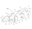
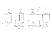
以下、図面を参照して、本発明のケーブル類保護案内装置の実施の形態としての実施例を説明する。ここで、図1は、本発明の一実施例であるケーブル類保護案内装置の斜視図であり、図2は、図1に示すリンク枠体の平面図であり、図3は、図2の3−3線で示した側断面図であり、図4は、屈曲内周側から見たケーブル類保護案内装置の直線状態を示す斜視図であり、図5は、リンクプレートの内周側端縁とリンク外れ防止溝部との係合を拡大して示す斜視図であり、図6は、屈曲内周側から見たケーブル類保護案内装置の屈曲状態を示す斜視図であり、図7は、リンクプレートの内周側端縁とリンク外れ防止切り欠き部との係合を拡大して示す斜視図である。 Hereinafter, with reference to the drawings, examples of embodiments of the cable protection and guide device of the present invention will be described. Here, FIG. 1 is a perspective view of a cable protection guide device according to an embodiment of the present invention, FIG. 2 is a plan view of the link frame shown in FIG. 1, and FIG. Fig. 4 is a side sectional view taken along line 3-3, Fig. 4 is a perspective view showing a linear state of the cable protection guide device viewed from the bent inner peripheral side, and Fig. 5 is an inner peripheral side end of the link plate. FIG. 6 is an enlarged perspective view showing engagement between the edge and the link detachment preventing groove, FIG. 6 is a perspective view showing a bent state of the cable protection guide device viewed from the bent inner peripheral side, and FIG. It is a perspective view which expands and shows engagement with the inner peripheral side edge of a link plate, and a link removal prevention notch part.
本実施例のケーブル類保護案内装置100は、例えば、プラズマディスプレイや半導体の製造装置や車両ドアなどの可動部と静止部とを接続する電気信号の伝達や電力の供給を行う電気ケーブルや油圧や空圧を供給するホースのようなケーブル類を保護案内するために使用されるものであって、図1に示すような矩形状のリンク枠体110が前述した可動部と静止部(図示しない)とを接続するために長尺状に多数連結され、可動部と静止部との間の移動状況に応じて直線状態、あるいは、屈曲状態を呈することができ、これらのリンク枠体110、110が連続して形成されたケーブル収容空間R内にケーブルCが挿通して保護案内できるようになっている。
The cable
前述したリンク枠体110は、優れた射出成形加工性を発揮することができるポリフッ化ビニリデン樹脂(PVDF)からなるフッ素系樹脂によって成形され、離間配置された左右一対のリンクプレート111、111と該リンクプレート111、111の屈曲内周側に横架された連結板112と屈曲外周側に横架された連結板113とが射出成形加工によって矩形状に一体化されている。
The
そして、リンクプレート111は、図2及び図3に示すように、プレート幅方向に段差を形成した、所謂、オフセット構造のもので、前側連結部111a及び後側連結部111bを有しており、これらの前側連結部111aと後側連結部111bとはプレート厚みが等しいが、プレート厚み分だけ相互にズレた段差を形成している。
また、前記後側連結部111bには連結ピン111cが設けられているとともに、前側連結部111aには連結ピン孔111dが設けられており、連結ピン孔111dは連結ピン111cを遊嵌させる内径を有している。
As shown in FIGS. 2 and 3, the
The
なお、前記リンクプレート111の後側連結部111bに設けた連結ピン111cは、連結し合うリンク枠体110、110が相互に捩れても連結ピン111cが連結ピン孔111dとの嵌合を連結し合うリンク枠体110、110の両者間で維持するようなピン丈、すなわち、リンクプレート111のプレート外表面上から突出した後に、連結し合うリンク枠体110の連結ピン孔111dを貫通してプレート外表面上に頭出しする程度のピン丈を有しており、リンク枠体110の連結ピン111cとこれと連結し合うリンク枠体110の連結ピン孔111dとの間に多少の形態変形を受けても、両者の凹凸嵌合状態が充分に維持されて外れることがないようになっている。
The connecting
また、図7における符号111eは、後側連結部111b側の最後端に設けてオフセットされた前側連結部111aと共動する直線状態での連結規制面であり、符号111fは、後側連結部111b側の最後端に設けてオフセットされた前側連結部111aと共動する屈曲状態での連結規制面である。
Moreover, the code |
そこで、本実施例におけるリンクプレート111、111の屈曲内周側に横架された連結板112の具体的な形態について以下のとおり詳しく説明する。
図1乃至図3に示すように、前記連結板112のケーブル収容空間R側に対面している左右両端112a、112aには、プレート厚みよりやや幅広のリンク外れ防止溝部111g、111gがリンクプレート111の長手方向に沿ってそれぞれ設けられている。
Therefore, a specific form of the
As shown in FIGS. 1 to 3, link
したがって、図4乃至図5に示すように、リンク枠体110、110が相互に直線状態で連結されているとき、リンク枠体110の左右に配置されたリンクプレート111、111の内周側端縁111h、111hは、連結されるリンク枠体110の屈曲内周側に横架された連結板112のリンク外れ防止溝部111g、111gにそれぞれ嵌まり込んで規制された状態で係合できるので、直線移動時において幅方向に生じがちな変形やズレを強制的に抑制できる。
Therefore, as shown in FIGS. 4 to 5, when the link frames 110 and 110 are connected to each other in a straight line state, the inner peripheral side ends of the
また、図1乃至図3に示すように、前記連結板112の左右両端112a、112aには、前述したリンク外れ防止溝部111g、111gに連続してリンクプレート111の長手方向に切り欠いたリンク外れ防止切り欠き部111k、111kがそれぞれ設けられている。
Further, as shown in FIGS. 1 to 3, the left and right ends 112a and 112a of the connecting
したがって、図6乃至図7に示すように、リンク枠体110、110が相互に屈曲状態で連結されているとき、リンク枠体110の左右に配置されたリンクプレート111、111の内周側端縁111h、111hは、連結されるリンク枠体110の屈曲内周側に横架された連結板112のリンク外れ防止切り欠き部111k、111kに嵌まり込んで規制された状態で係合できるので、屈曲移動時においても幅方向に生じがちな変形やズレを強制的に抑制できる。
Therefore, as shown in FIGS. 6 to 7, when the link frames 110 and 110 are connected to each other in a bent state, the inner peripheral side ends of the
このようにして、本実施例のケーブル類保護案内装置100は、プラズマディスプレイや半導体などの製造装置に組み込まれて、可動部が移動すると、その移動ストロークに応じてリンク枠体110が直線状態及び屈曲状態となって、ケーブルCを保護しつつ案内することができる。
そして、本実施例のケーブル類保護案内装置100では、リンク外れ防止溝部111gとリンク外れ防止切り欠き部111kが、リンク枠体110の組み付け構造に関連せずに、屈曲内周側に横架された連結板112の左右両端112a、112aにそれぞれ設けられていることによって、リンク枠体110の連結組み付け作業が簡便となり、また、成形金型の複雑な構造を回避できるため、成形精度が安定して成形金型のコスト負担が低減され、しかも、リンク枠体が相互に直線状態で連結されているとき、リンクプレート111、111の内周側端縁111h、111hがリンク外れ防止溝部111g、111gに嵌まり込んで規制された状態で係合し、また、リンク枠体110が相互に屈曲状態で連結されているとき、リンクプレート111、111の内周側端縁111h、111hがリンク外れ防止切り欠き部111k、111kに嵌まり込んで規制された状態で係合して幅方向に生じがちな変形やズレを強制的に抑制できるため、直線移動中や屈曲移動中にリンク枠体110が捩れや撓みを受けてもリンク枠体110同士の相互連結を確実に保持できるなど、その効果は甚大である。
In this way, the cable protection and
In the cable
100 ・・・ケーブル類保護案内装置
110 ・・・リンク枠体
111 ・・・リンクプレート
111a・・・前側連結部
111b・・・後側連結部
111c・・・連結ピン
111d・・・連結ピン孔
111g・・・リンク外れ防止溝部
111h・・・内周側端縁
111k・・・リンク外れ防止切り欠き部
112 ・・・リンクプレート111の屈曲内周側に横架された連結板
112a・・・連結板112の左右両端
113 ・・・リンクプレート111の屈曲外周側に横架された連結板
C ・・・ケーブル
R ・・・ケーブル収容空間
DESCRIPTION OF
Claims (2)
前記リンク枠体が相互に直線状態で連結されているときに前記リンクプレートの内周側端縁に嵌まり込んで幅方向に生じがちなリンクプレートの変形やズレを規制した状態で係合するリンク外れ防止溝部が、前記リンク枠体の屈曲内周側に横架された連結板の左右両端にそれぞれ設けられていることを特徴とするケーブル類保護案内装置。 A connecting pin and a connecting pin hole provided on the link plate by a rectangular link frame body comprising a pair of left and right link plates that are spaced apart from each other, and a connecting plate that is horizontally mounted on the bent inner peripheral side and the bent outer peripheral side of the link plate. In a cable protection guide device for connecting and guiding a plurality of cables in a cable housing space formed by connecting the link frame bodies so as to be bent with respect to each other,
When the link frame members are connected to each other in a straight line state, the link frame members are engaged with each other in a state in which they are fitted into the inner peripheral side edge of the link plate and the deformation and displacement of the link plate that tend to occur in the width direction are restricted. A cable protection guide device, characterized in that a link disconnection preventing groove is provided on each of the left and right ends of a connecting plate that is laid across the bent inner periphery of the link frame.
Priority Applications (6)
| Application Number | Priority Date | Filing Date | Title |
|---|---|---|---|
| JP2004136041A JP3897352B2 (en) | 2004-04-30 | 2004-04-30 | Cable protection guide device |
| US10/958,096 US7387046B2 (en) | 2004-04-30 | 2004-10-04 | Cable protection and guide device |
| DE102004050979.4A DE102004050979B4 (en) | 2004-04-30 | 2004-10-15 | Protection and guiding device for a cable or a hose |
| IT000097A ITGE20040097A1 (en) | 2004-04-30 | 2004-10-20 | PROTECTION AND GUIDE FOR A CABLE OR SIMILAR |
| KR1020040087224A KR100826070B1 (en) | 2004-04-30 | 2004-10-29 | Cable or the like protection and guide device |
| CNB2004100880347A CN100479287C (en) | 2004-04-30 | 2004-10-29 | Cable protection and guide device |
Applications Claiming Priority (1)
| Application Number | Priority Date | Filing Date | Title |
|---|---|---|---|
| JP2004136041A JP3897352B2 (en) | 2004-04-30 | 2004-04-30 | Cable protection guide device |
Publications (2)
| Publication Number | Publication Date |
|---|---|
| JP2005315382A JP2005315382A (en) | 2005-11-10 |
| JP3897352B2 true JP3897352B2 (en) | 2007-03-22 |
Family
ID=35220069
Family Applications (1)
| Application Number | Title | Priority Date | Filing Date |
|---|---|---|---|
| JP2004136041A Expired - Lifetime JP3897352B2 (en) | 2004-04-30 | 2004-04-30 | Cable protection guide device |
Country Status (6)
| Country | Link |
|---|---|
| US (1) | US7387046B2 (en) |
| JP (1) | JP3897352B2 (en) |
| KR (1) | KR100826070B1 (en) |
| CN (1) | CN100479287C (en) |
| DE (1) | DE102004050979B4 (en) |
| IT (1) | ITGE20040097A1 (en) |
Families Citing this family (19)
| Publication number | Priority date | Publication date | Assignee | Title |
|---|---|---|---|---|
| ITBO20070066A1 (en) * | 2007-02-01 | 2008-08-02 | Franceschi Daniele De | POLYFUNCTION LOCK AND ORGAN SERVOMOTOR ACTUATOR ROLLED ON INTERCHANGEABLE SPROCKET |
| WO2008106541A2 (en) * | 2007-02-27 | 2008-09-04 | Carnegie Mellon University | System for releasably attaching a disposable device to a durable device |
| JP4420934B2 (en) | 2007-03-29 | 2010-02-24 | 株式会社椿本チエイン | Cable protection guide device |
| JP5040434B2 (en) * | 2007-05-16 | 2012-10-03 | 住友電装株式会社 | Routing structure for sliding door harness |
| JP4751862B2 (en) * | 2007-08-08 | 2011-08-17 | 株式会社椿本チエイン | Cable protection guide device |
| CN102292013B (en) | 2008-09-05 | 2015-05-27 | 卡内基梅隆大学 | Multi-linked endoscopic device with spherical distal assembly |
| CN102983532A (en) * | 2011-09-07 | 2013-03-20 | 温芫鋐 | Connecting pipes of bicycle wire sheath and bicycle wire sheath provided with the same |
| CN102494191B (en) * | 2011-11-15 | 2013-11-20 | 山西四建集团有限公司 | Installation method of arc cable tray |
| KR20150013293A (en) * | 2012-07-04 | 2015-02-04 | 닛뽕소다 가부시키가이샤 | Functional anti-reflection laminate |
| DE202014103562U1 (en) | 2014-07-31 | 2014-09-11 | Igus Gmbh | guide means |
| CN105896392A (en) * | 2014-10-27 | 2016-08-24 | 无锡市神力通信工程有限公司 | Cable holding clamp support frame |
| TWM506906U (en) | 2015-02-06 | 2015-08-11 | Molex Taiwan Ltd | Cable guide protection chain |
| DE102015211271B3 (en) * | 2015-06-18 | 2016-11-17 | Ford Global Technologies, Llc | Fastening device for a cable |
| JP6430991B2 (en) * | 2016-04-15 | 2018-11-28 | 矢崎総業株式会社 | Bending restriction member and power feeding device |
| FR3055061B1 (en) * | 2016-08-11 | 2018-08-24 | Peugeot Citroen Automobiles Sa | MOBILE SCREEN FOR VEHICLE |
| JP6457992B2 (en) * | 2016-11-22 | 2019-01-23 | 矢崎総業株式会社 | Bending restriction member and power feeding device |
| JP6474875B1 (en) * | 2017-10-17 | 2019-02-27 | 株式会社国盛化学 | Cable chain |
| CN109650175B (en) * | 2018-12-29 | 2020-12-22 | 三一海洋重工有限公司 | Novel cable guide frame and control method thereof |
| CN112970158B (en) * | 2019-01-30 | 2022-11-15 | 华为海洋网络有限公司 | Bending limiter |
Family Cites Families (16)
| Publication number | Priority date | Publication date | Assignee | Title |
|---|---|---|---|---|
| DE3333543C3 (en) * | 1983-09-16 | 1995-02-09 | Ernst Klein | Self-supporting energy conductor |
| DE3431531A1 (en) * | 1984-08-28 | 1986-03-06 | Igus GmbH, 5060 Bergisch Gladbach | Energy supply chain |
| JPH02186146A (en) | 1989-01-09 | 1990-07-20 | Oriental Chain Kogyo Kk | Closed type cable support chain |
| DE8901955U1 (en) * | 1989-02-18 | 1989-04-06 | Kabelschlepp Gmbh, 5900 Siegen, De | |
| JP2589014B2 (en) | 1991-07-31 | 1997-03-12 | 株式会社椿本チエイン | Cable drag chain distortion prevention structure |
| DE4413303C1 (en) * | 1994-04-18 | 1995-05-24 | Kabelschlepp Gmbh | Traverse for energy supply chain |
| US5724803A (en) * | 1995-05-04 | 1998-03-10 | Hubbell Incorporated | Power supply chain with roller bar carrier |
| GB9724402D0 (en) * | 1997-11-19 | 1998-01-14 | Mansign Mining Equipment Ltd | Cable/hose handling chain |
| JP3157491B2 (en) * | 1997-11-28 | 2001-04-16 | 株式会社椿本チエイン | Flexible guide support chain |
| AUPQ350399A0 (en) * | 1999-10-18 | 1999-11-11 | Senior Thermal Engineering Australia Pty Limited | Chain for carrying hose or cable |
| JP3356758B2 (en) | 2000-09-13 | 2002-12-16 | 株式会社椿本チエイン | Cable drag chain |
| JP3669694B2 (en) * | 2002-03-22 | 2005-07-13 | 株式会社椿本チエイン | Cable drag chain |
| JP3722482B2 (en) * | 2003-02-17 | 2005-11-30 | 株式会社椿本チエイン | Cable protection guide device |
| JP4144869B2 (en) * | 2003-09-11 | 2008-09-03 | 株式会社椿本チエイン | Cable protection guide device |
| JP4136905B2 (en) * | 2003-11-13 | 2008-08-20 | 株式会社椿本チエイン | Horizontally installed cable protection guide device |
| JP2005147233A (en) * | 2003-11-13 | 2005-06-09 | Tsubakimoto Chain Co | Apparatus for protectively guiding cable |
-
2004
- 2004-04-30 JP JP2004136041A patent/JP3897352B2/en not_active Expired - Lifetime
- 2004-10-04 US US10/958,096 patent/US7387046B2/en active Active
- 2004-10-15 DE DE102004050979.4A patent/DE102004050979B4/en active Active
- 2004-10-20 IT IT000097A patent/ITGE20040097A1/en unknown
- 2004-10-29 KR KR1020040087224A patent/KR100826070B1/en active IP Right Grant
- 2004-10-29 CN CNB2004100880347A patent/CN100479287C/en active Active
Also Published As
| Publication number | Publication date |
|---|---|
| DE102004050979B4 (en) | 2021-06-10 |
| CN1694326A (en) | 2005-11-09 |
| US20050252192A1 (en) | 2005-11-17 |
| ITGE20040097A1 (en) | 2005-01-20 |
| JP2005315382A (en) | 2005-11-10 |
| DE102004050979A1 (en) | 2005-11-24 |
| KR20050105093A (en) | 2005-11-03 |
| US7387046B2 (en) | 2008-06-17 |
| CN100479287C (en) | 2009-04-15 |
| KR100826070B1 (en) | 2008-04-29 |
Similar Documents
| Publication | Publication Date | Title |
|---|---|---|
| JP3897352B2 (en) | Cable protection guide device | |
| JP4540722B2 (en) | Cable protection guide device | |
| JP4302752B2 (en) | Cable protection guide device | |
| JP4111958B2 (en) | Cable protection guide device | |
| JP4098275B2 (en) | Cable protection guide device | |
| US7132602B1 (en) | Cable or the like clamp member for cable or the like protection and guide device | |
| KR101184113B1 (en) | Cable or the like protection guide device | |
| JP5618933B2 (en) | Cable protection guide device | |
| US7045705B2 (en) | Cable protection and guide device | |
| JP2009041631A5 (en) | ||
| JP4136905B2 (en) | Horizontally installed cable protection guide device | |
| US20080236131A1 (en) | Cable protection and guide device | |
| US7017328B2 (en) | Cable protection and guide device | |
| US7119273B2 (en) | Cables or the like protection and guide device | |
| JP2006109613A (en) | Cables-protection guide device | |
| JP4717599B2 (en) | Flexible cable duct | |
| JP4170308B2 (en) | Fiber optic cable fixture | |
| JP6576837B2 (en) | Long body for moving parts |
Legal Events
| Date | Code | Title | Description |
|---|---|---|---|
| A977 | Report on retrieval |
Free format text: JAPANESE INTERMEDIATE CODE: A971007 Effective date: 20060426 |
|
| A131 | Notification of reasons for refusal |
Free format text: JAPANESE INTERMEDIATE CODE: A131 Effective date: 20060530 |
|
| A521 | Written amendment |
Free format text: JAPANESE INTERMEDIATE CODE: A523 Effective date: 20060612 |
|
| TRDD | Decision of grant or rejection written | ||
| A01 | Written decision to grant a patent or to grant a registration (utility model) |
Free format text: JAPANESE INTERMEDIATE CODE: A01 Effective date: 20061215 |
|
| A61 | First payment of annual fees (during grant procedure) |
Free format text: JAPANESE INTERMEDIATE CODE: A61 Effective date: 20061218 |
|
| R150 | Certificate of patent or registration of utility model |
Free format text: JAPANESE INTERMEDIATE CODE: R150 Ref document number: 3897352 Country of ref document: JP Free format text: JAPANESE INTERMEDIATE CODE: R150 |
|
| FPAY | Renewal fee payment (event date is renewal date of database) |
Free format text: PAYMENT UNTIL: 20110105 Year of fee payment: 4 |
|
| FPAY | Renewal fee payment (event date is renewal date of database) |
Free format text: PAYMENT UNTIL: 20120105 Year of fee payment: 5 |
|
| FPAY | Renewal fee payment (event date is renewal date of database) |
Free format text: PAYMENT UNTIL: 20130105 Year of fee payment: 6 |
|
| FPAY | Renewal fee payment (event date is renewal date of database) |
Free format text: PAYMENT UNTIL: 20140105 Year of fee payment: 7 |