EP3175144B1 - Kettenspannungsstange - Google Patents
Kettenspannungsstange Download PDFInfo
- Publication number
- EP3175144B1 EP3175144B1 EP15759543.0A EP15759543A EP3175144B1 EP 3175144 B1 EP3175144 B1 EP 3175144B1 EP 15759543 A EP15759543 A EP 15759543A EP 3175144 B1 EP3175144 B1 EP 3175144B1
- Authority
- EP
- European Patent Office
- Prior art keywords
- chain
- supporting surface
- tensioning rod
- shoe
- supporting
- Prior art date
- Legal status (The legal status is an assumption and is not a legal conclusion. Google has not performed a legal analysis and makes no representation as to the accuracy of the status listed.)
- Active
Links
Images

Classifications
-
- F—MECHANICAL ENGINEERING; LIGHTING; HEATING; WEAPONS; BLASTING
- F16—ENGINEERING ELEMENTS AND UNITS; GENERAL MEASURES FOR PRODUCING AND MAINTAINING EFFECTIVE FUNCTIONING OF MACHINES OR INSTALLATIONS; THERMAL INSULATION IN GENERAL
- F16H—GEARING
- F16H7/00—Gearings for conveying rotary motion by endless flexible members
- F16H7/08—Means for varying tension of belts, ropes or chains
-
- F—MECHANICAL ENGINEERING; LIGHTING; HEATING; WEAPONS; BLASTING
- F16—ENGINEERING ELEMENTS AND UNITS; GENERAL MEASURES FOR PRODUCING AND MAINTAINING EFFECTIVE FUNCTIONING OF MACHINES OR INSTALLATIONS; THERMAL INSULATION IN GENERAL
- F16H—GEARING
- F16H7/00—Gearings for conveying rotary motion by endless flexible members
- F16H7/18—Means for guiding or supporting belts, ropes, or chains
-
- F—MECHANICAL ENGINEERING; LIGHTING; HEATING; WEAPONS; BLASTING
- F16—ENGINEERING ELEMENTS AND UNITS; GENERAL MEASURES FOR PRODUCING AND MAINTAINING EFFECTIVE FUNCTIONING OF MACHINES OR INSTALLATIONS; THERMAL INSULATION IN GENERAL
- F16H—GEARING
- F16H7/00—Gearings for conveying rotary motion by endless flexible members
- F16H7/08—Means for varying tension of belts, ropes or chains
- F16H2007/0802—Actuators for final output members
- F16H2007/0804—Leaf springs
-
- F—MECHANICAL ENGINEERING; LIGHTING; HEATING; WEAPONS; BLASTING
- F16—ENGINEERING ELEMENTS AND UNITS; GENERAL MEASURES FOR PRODUCING AND MAINTAINING EFFECTIVE FUNCTIONING OF MACHINES OR INSTALLATIONS; THERMAL INSULATION IN GENERAL
- F16H—GEARING
- F16H7/00—Gearings for conveying rotary motion by endless flexible members
- F16H7/08—Means for varying tension of belts, ropes or chains
- F16H2007/0863—Finally actuated members, e.g. constructional details thereof
- F16H2007/0872—Sliding members
-
- F—MECHANICAL ENGINEERING; LIGHTING; HEATING; WEAPONS; BLASTING
- F16—ENGINEERING ELEMENTS AND UNITS; GENERAL MEASURES FOR PRODUCING AND MAINTAINING EFFECTIVE FUNCTIONING OF MACHINES OR INSTALLATIONS; THERMAL INSULATION IN GENERAL
- F16H—GEARING
- F16H7/00—Gearings for conveying rotary motion by endless flexible members
- F16H7/08—Means for varying tension of belts, ropes or chains
- F16H2007/0889—Path of movement of the finally actuated member
- F16H2007/0893—Circular path
Definitions
- the present invention is related to a chain-tensioning rod of the type used in an internal combustion engine to keep in tension the timing chain, that is the chain transferring the motion from the crankshaft to the camshaft in a so-called overhead camshaft engine.
- timing chain can be meant a roller chain, which is engaged with toothed wheels: pinion and crown.
- this type of rod generally comprises a portion, called shoe, made of resin, which is hinged at its own end and it is pressed against the outer surface of a chain or a timing belt to implement the best tensioning thereof, needed to guarantee the maximum precision in the actuation of the camshaft.
- the shoe resin is selected so as to guarantee the minimum friction in the pressing site, but it is not a suitable material to guarantee the required mechanical integrity of the rod.
- the chain-tensioning rod comprises a metallic arm, thereby said hinge is made and supporting the shoe.
- the rod has to be as much as light and elastic as possible.
- European patent No. 1,441,149 describes a chain-tensioning rod wherein the assembly between the two above-described elements is guaranteed by giving a particular shape to the contact element thereon an outer mechanical organ exerts the required pressure on the rod.
- the rod arm is thus constituted by a solid metallic strip, fixed laterally to the shoe.
- This asymmetrical hook-like shape implements an insertion of the arm into the shoe thanks to a rotary motion with a certain complexity and even makes the entire set unstable, both due to the asymmetry and as the arm is not constrained to the shoe for the whole length thereof.
- US patent No. 5,318,482 describes a chain-tensioning rod wherein the contact element, in order to allow the assembling with the arm, is not constructed as single piece with the shoe but it is a detached portion, which has to be connected to the shoe by fixing the arm thereto.
- the metallic arm has a complex shape and provides a central opening and perpendicular raised edges which are complementary to the shape of the shoe. This much more complex solution, then, comprises an intrinsic weakness in the fastening thereof between said two portions.
- US patent application No. 2013/0210566 instead, describes a single-piece shoe comprising, at the area in contact with the chain, a strip made of synthetic material inserted in a longitudinal guide. Even this solution is very complex as the previous one.
- US patent No. 4,921,472 A describes a shoe with supporting arm, which is constrained to the shoe at the two ends thereof, by determining some difficulties in the assembly of the two portions.
- European patnt application No. 1,182,378 A2 discolses a chain tensioner blade having a supporting bracket and a blade shoe supported on the bracket.
- the technical problem underlying the present invention is to provide a chain-tensioning rod allowing to obviate the drawbacks mentioned with reference to the known art.
- the main advantage of the chain-tensioning rod according to the present invention lies in allowing a simple assembly of the arm and of the relative shoe.
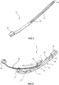
- a chain-tensioning rod is designated as a whole with 1. It is of the type which is used in an internal combustion engine with overhead camshaft valvetrain, to keep tensioned the timing chain transferring the motion from a pinion connected to the crankshaft to another wheel, called crown, connected to the camshaft.
- the rod 1 has an elongated shape extending between a proximal end 2, thereat the rod 1 is hinged inside the engine, and a distal end 3.
- the rod 1 is substantially embodied by two distinct portions.
- a first portion relates to a shoe 4 ( figure 2 ) generally made of a synthetic material, particularly of resin, allowing to implement a low friction with the outer surface of the transmission chain.
- the shoe 4 is pressed by an actuator (not shown) so that it exerts a pressure on the chain, thus by keeping it in tension.
- the shoe is formed by a monolithic piece in resin, produced by injection moulding, and it has a smooth sliding surface 5 at one exposed side of the rod 1. Such surface can be delimited by longitudinal raised edges 11, which thus define a guide for the chain.
- the shoe 4 has a central portion 12 with a larger width and two end portions 13 and 14 with a slightly smaller width.
- the shoe 4 has a supporting surface 6 thereat it is pressed by said actuator.
- the supporting surface 6 substantially extends from the proximal end 2 to the distal end 3 of the rod 1.
- the contact element 7 is not a solid block of material, but it has lightening side grooves 9.
- the contact element 7 is supported in a raised position with respect to said supporting surface 6, being connected thereto by means of a first connecting rib 10, longitudinally developing along the supporting surface 6 and in a central position with respect thereto, rising perpendicularly and thus constituting the central core of the contact element 7.
- the shoe 4 comprises an eyelet-like portion 15 formed by two portions projecting from the proximal end portion 13. They form, respectively, an eyelet 16, with a circular opening the axis thereof is perpendicular to the development of the rod 1, and a curved wall 17 representing the extension of the supporting surface 6.
- the eyelet 16 is formed by a holed wall extending from a longitudinal margin of the supporting surface 6 at the proximal end 2.
- the shoe 4 comprises a hook-like portion 18 formed by a wall which, extending from the supporting surface 6, folds by 180° by forming a recess 19 between itself and the supporting surface 6.
- Said wall is further connected to the supporting surface 6 by a second connecting rib 20, which, like the first one, longitudinally develops along the supporting surface 6 and in a central position with respect thereto, perpendicularly rising and thus constituting the central core of the hook-like portion 18.
- the shoe 4 comprises stopping elements: edging tracts rising from said margins perpendicularly to the surface 6.
- the shoe 4 comprises a proximal stopping element 21 on the proximal end portion 13, the position thereof is placed on the opposite margin with respect to the one whereon said eyelet-like portion 16 is placed.
- the shoe described so far further comprises a pair of distal stopping elements 22, 23, arranged on opposite margins of the supporting surface 6. These distal stopping elements 22, 23 are staggered therebetween and, as it will appear clearly hereinafter, together with the proximal stopping element 21 and the two connecting ribs 10, 20, constitute guides of the arm of the chain-tensioning rod 1.
- the second one of said portions constituting the rod 1 is then a supporting arm 25 which is formed by an elongated blade obtained from a curved band with substantially constant thickness, made of metal, for example harmonic steel.
- the supporting arm 25 ( figure 3 ) is monolithic, obtained by punching and finishing from an unfinished metallic piece.
- the supporting arm 25 in turn extends between the opposite ends and it comprises, at the proximal end, a ring-like shape 26 apt to couple with the eyelet-like portion 15 to form therewith a hinge element apt to be engaged by a (not represented) pin connected to the engine.
- the arm 25 then comprises a longitudinal pass-through slit 27 extending from the distal end, wherein the slit is open, having then an inlet mouth 28, for at least half length of the arm 25.
- the slit 27 extends between said distal end for at least half length of the supporting arm 25, so as to be able to extend from the distal end 3 of the shoe as far as including the whole first rib 10 of the contact element 7.
- the slit 27 has a constant width, it is positioned symmetrically in a central position with respect to the arm 25, and ends with a stopping end 29.
- the arm 25 and the shoe 4 are overlapped, so that the extrados of the arm 25 is in contact with the proximal end portion 13 of the shoe 4.
- the overlapping takes place by making the supporting arm 25 to slide on the supporting surface 6 from the proximal end 2 of the rod 1, until the first connecting rib 10 of the contact element 7 is inserted in the mouth of the slit 27 and it is made to slide as far as even the second rib 20 enters the slit 27.
- the distal end of the arm 25 inserts inside the hook-like portion 18 reaching the end thereof; furthermore, the stopping end 29 of the slit 27 is in contact with the first rib 10 and, at last, the ring 26 couples with the eyelet-like portion 15.
- arm 25 and shoe 4 translate longitudinally one with respect to the other one, without having to resort to rotations of any type.
- the first connecting rib 10 acts as transversal and central locking device of the arm 25 on the supporting surface 6 of the shoe 4.
Landscapes
- Engineering & Computer Science (AREA)
- General Engineering & Computer Science (AREA)
- Mechanical Engineering (AREA)
- Devices For Conveying Motion By Means Of Endless Flexible Members (AREA)
Claims (12)
- Kettenspannstange (1), von dem Typ, wie sie in einem Verbrennungsmotor mit einem obenliegenden Nockenwellenventilzug verwendet wird, um eine Steuerkette unter Spannung zu halten, umfassend einen Schuh (4), der gegen die Steuerkette gedrückt wird, und einen Stützarm (25) des Schuhs, dadurch gekennzeichnet, dass:- der Schuh (4) durch ein monolithisches Stück gebildet ist, das auf einer Seite davon eine Gleitfläche (5) und auf der gegenüberliegenden Seite eine Stützfläche (6) und ein Kontaktelement (7) aufweist, das mit der Stützfläche (6) an einem mittleren Abschnitt des Schuhs (4) mittels einer Verbindungsrippe (10) verbunden ist, die sich in Längsrichtung entlang der Stützfläche (6) und in deren Mitte erstreckt, wobei die Stützfläche (6) sich von einem proximalen Ende (2) erstreckt, an dem die Kettenspannstange angelenkt ist, und ein distales Ende (3);- der Stützarm (25) wird durch eine längliche Schneide gebildet, die einen länglichen Durchgangsschlitz (27) aufweist, der sich von einem distalen Ende derselben erstreckt, wobei dieser zumindest über die halbe Länge des Stützarmes (25) offen ist,so dass das Einführen des Stützarms (25) auf der Stützfläche (6) erfolgt, indem der Stützarm (25) von dem proximalen Ende (2) auf der Stützfläche (6) gleitend geführt wird, indem die Verbindungsrippe (10) in den Schlitz (27) eingeführt wird, wobei die Verbindungsrippe (10) als Querverriegelungsvorrichtung des Stützarms (25) auf der Stützfläche (6) wirkt.
- Kettenspannstange (1) nach Anspruch 1, wobei das Kontaktelement (7) gegenüber der Stützfläche (6) in einer angehobenen Position von der Verbindungsrippe (10) abgestützt ist, die senkrecht ansteigt und den mittleren Kern des Kontaktelements (7) bildet.
- Kettenspannstange (1) nach Anspruch 2, wobei das Kontaktelement (7) eine Parallelepiped-Form und eine Kontaktfläche (8) aufweist, die im Abstand und parallel zur Stützfläche (6) angeordnet ist.
- Kettenspannstange (1) nach Anspruch 1, wobei an deren proximalen Ende (2) der Schuh (4) einen ösenartigen Abschnitt (15) aufweist; und wobei der Stützarm (25) an dem proximalen Ende (2) eine ringartige Form (26) aufweist, die geeignet ist, mit dem ösenartigen Abschnitt (15) zu kuppeln, um damit ein Scharnierelement zu bilden, das dazu geeignet ist durch einen Stift, der mit dem Motor verbunden ist, in Eingriff zu kommen.
- Kettenspannstange (1) nach Anspruch 4, wobei der ösenartigen Abschnitt (15) durch zwei Abschnitte gebildet ist, die vorstehen und jeweils eine Öse bilden (16), mit einer kreisförmigen Öffnung, deren Achse senkrecht zu dem Verlauf der Kettenspannstange (1) ist, und einer gekrümmten Wand (17), die die Verlängerung der Stützfläche (6) darstellt, wobei die Öse 16 durch eine Lochwand gebildet wird, die sich von einem Längsrand der Stützfläche (6) an dem proximalen Ende (2) erstreckt.
- Kettenspannstange (1) nach Anspruch 1, wobei der Schuh (4) an einem distalen Ende (3) der Kettenspannstange (1) einen hakenartigen Abschnitt (18) umfasst, der durch eine Wand gebildet ist, welche sich von der Stützfläche (6) aus um 180 ° faltet, indem zwischen sich selber und der Stützfläche (6) eine Ausnehmung (19) gebildet wird.
- Kettenspannstange (1) nach Anspruch 6, wobei der hakenartige Abschnitt (18) mit der Stützfläche (6) durch eine zusätzliche Längs- und Mittelverbindungsrippe (20) verbunden ist, die geeignet ist, in den Schlitz (27) des Stützarmes (25) eingeführt zu werden.
- Kettenspannstange (1) nach Anspruch 1, wobei der Schuh (4) an den äußeren Rändern der Stützfläche (6) Anschlagelemente aufweist, die durch Randteile gebildet sind, die von den Rändern senkrecht zu der Stützfläche (6) aufsteigen.
- Kettenspannstange (1) nach den Ansprüchen 5 und 8, wobei der Schuh (4) ein proximales Anschlagelement (21) an seinem eigenen proximalen Endabschnitt (13) umfasst, dessen Position auf dem gegenüberliegenden Rand bezüglich dem auf dem die ösenartige Form (16) platziert ist, platziert wird.
- Kettenspannstange (1) nach Anspruch 8, wobei der Schuh (4) ein Paar distaler Anschlagelemente (22, 23) umfasst, die an gegenüberliegenden Rändern der Stützfläche (6) angeordnet sind und dazwischen versetzt sind.
- Kettenspannstange (1) nach Anspruch 1, wobei der Schlitz (27) eine konstante Breite aufweist, symmetrisch in der zentralen Position in Bezug auf den Stützarm (25) positioniert ist und mit einem Anschlagende (29) endet, welches mit der Rippe (10) in Kontakt kommt.
- Kettenspannstange (1) nach Anspruch 1, wobei der Stützarm (25) aus Metall, beispielsweise Federstahl, hergestellt ist.
Applications Claiming Priority (3)
| Application Number | Priority Date | Filing Date | Title |
|---|---|---|---|
| ITRM20140451 | 2014-08-01 | ||
| ITRM20140450 | 2014-08-01 | ||
| PCT/IB2015/055766 WO2016016836A2 (en) | 2014-08-01 | 2015-07-30 | Chain-tensioning rod |
Publications (2)
| Publication Number | Publication Date |
|---|---|
| EP3175144A2 EP3175144A2 (de) | 2017-06-07 |
| EP3175144B1 true EP3175144B1 (de) | 2018-10-17 |
Family
ID=54062777
Family Applications (1)
| Application Number | Title | Priority Date | Filing Date |
|---|---|---|---|
| EP15759543.0A Active EP3175144B1 (de) | 2014-08-01 | 2015-07-30 | Kettenspannungsstange |
Country Status (6)
| Country | Link |
|---|---|
| US (1) | US10408311B2 (de) |
| EP (1) | EP3175144B1 (de) |
| JP (1) | JP6535729B2 (de) |
| CN (1) | CN106536982B (de) |
| ES (1) | ES2702283T3 (de) |
| WO (1) | WO2016016836A2 (de) |
Families Citing this family (3)
| Publication number | Priority date | Publication date | Assignee | Title |
|---|---|---|---|---|
| CN107981858B (zh) | 2017-11-27 | 2020-12-01 | 上海优加利健康管理有限公司 | 基于人工智能的心电图心搏自动识别分类方法 |
| JP7277732B2 (ja) * | 2019-05-15 | 2023-05-19 | 株式会社椿本チエイン | テンショナレバー |
| US11815180B2 (en) * | 2021-08-24 | 2023-11-14 | Schaeffler Technologies AG & Co. KG | Tensioner with stamped pivot pin |
Family Cites Families (17)
| Publication number | Priority date | Publication date | Assignee | Title |
|---|---|---|---|---|
| GB1172716A (en) * | 1967-05-31 | 1969-12-03 | Borge Warner Ltd | Chain Tensioner. |
| US4921472A (en) * | 1989-06-12 | 1990-05-01 | Borg-Warner Automotive Transmission & Engine Components Corporation | Chain tensioner |
| JPH089476Y2 (ja) | 1991-11-07 | 1996-03-21 | 株式会社椿本チエイン | チェーンガイドのアームとシューの一体化構造 |
| JP3961612B2 (ja) * | 1997-04-18 | 2007-08-22 | 株式会社椿本チエイン | テンショナレバー |
| JP2000230611A (ja) * | 1999-02-15 | 2000-08-22 | Borg Warner Automotive Kk | ブレードテンショナ |
| GB0020908D0 (en) * | 2000-08-25 | 2000-10-11 | Renold Plc | Chain or belt tensioner |
| JP3998576B2 (ja) * | 2000-10-17 | 2007-10-31 | クロイズ ギア アンド プロダクツ インコーポレイテッド | 外部補強リブを備えるブレード型機械チェーンテンショナ |
| JP3550548B2 (ja) * | 2001-02-02 | 2004-08-04 | ボルグワーナー・モールステック・ジャパン株式会社 | ブレードスプリング用クリップおよび該クリップを備えたブレードテンショナ |
| JP3532179B2 (ja) | 2001-10-31 | 2004-05-31 | 本田技研工業株式会社 | カムチェーンテンショナ |
| JP3359340B1 (ja) * | 2002-01-23 | 2002-12-24 | 株式会社椿本チエイン | 伝動装置用可動ガイド |
| JP4312107B2 (ja) * | 2004-06-15 | 2009-08-12 | 株式会社椿本チエイン | 伝動装置用合成樹脂ガイド |
| JP2009103186A (ja) | 2007-10-22 | 2009-05-14 | Tsubakimoto Chain Co | 伝動装置用ガイド |
| WO2010059698A1 (en) * | 2008-11-18 | 2010-05-27 | Cloyes Gear And Products, Inc. | Blade tensioner with captured spring |
| JP2013164134A (ja) * | 2012-02-10 | 2013-08-22 | Tsubakimoto Chain Co | 伝動装置用チェーンガイド |
| DE102012206664B4 (de) * | 2012-04-23 | 2016-01-14 | Schaeffler Technologies AG & Co. KG | Mechanische Kettenspanneinheit mit Federbandstahltragkörper und Keilnachstellvorrichtung |
| JP5980177B2 (ja) * | 2013-07-22 | 2016-08-31 | 株式会社椿本チエイン | チェーンガイド |
| JP6539244B2 (ja) * | 2016-09-30 | 2019-07-03 | 本田技研工業株式会社 | 内燃機関 |
-
2015
- 2015-07-30 EP EP15759543.0A patent/EP3175144B1/de active Active
- 2015-07-30 CN CN201580035194.1A patent/CN106536982B/zh active Active
- 2015-07-30 JP JP2017503891A patent/JP6535729B2/ja active Active
- 2015-07-30 US US15/320,939 patent/US10408311B2/en active Active
- 2015-07-30 ES ES15759543T patent/ES2702283T3/es active Active
- 2015-07-30 WO PCT/IB2015/055766 patent/WO2016016836A2/en not_active Ceased
Non-Patent Citations (1)
| Title |
|---|
| None * |
Also Published As
| Publication number | Publication date |
|---|---|
| EP3175144A2 (de) | 2017-06-07 |
| ES2702283T3 (es) | 2019-02-28 |
| JP2017524104A (ja) | 2017-08-24 |
| WO2016016836A2 (en) | 2016-02-04 |
| US10408311B2 (en) | 2019-09-10 |
| CN106536982A (zh) | 2017-03-22 |
| US20170152923A1 (en) | 2017-06-01 |
| JP6535729B2 (ja) | 2019-06-26 |
| WO2016016836A3 (en) | 2016-03-24 |
| CN106536982B (zh) | 2019-06-04 |
Similar Documents
| Publication | Publication Date | Title |
|---|---|---|
| KR101471701B1 (ko) | 체인 가이드 기구 | |
| EP3175144B1 (de) | Kettenspannungsstange | |
| US8789245B2 (en) | Extensible clasp for a wrist strap in particular of a watch | |
| JP6289806B2 (ja) | 異なるリストバンド長さ調節機構付き留め金 | |
| US8601784B2 (en) | Anti-rotation link | |
| KR20110049714A (ko) | 체인 가이드 기구 | |
| US7951029B2 (en) | Guide for transmission device | |
| RU2650915C2 (ru) | Застежка браслета, содержащая устройство для регулировки рабочей длины браслета | |
| JP2010510844A (ja) | 長さ調節装置を備えたブレスレットの留め金 | |
| BRPI0820489B1 (pt) | perfil de correia e correia modelada | |
| JP2020093092A (ja) | 調整可能なバンド中留 | |
| ITTO930827A1 (it) | Fascetta, in particolare fascetta per tubi flessibili | |
| US10738862B2 (en) | Chain guide mechanism | |
| JP2020093094A (ja) | 調整可能なバンド中留 | |
| US20090089980A1 (en) | Device for the fine adjustment of the useful length of a wrist strap, such as the wrist strap of a watch | |
| BRPI1106248B1 (pt) | dispositivo tensor de corrente | |
| HK1235450A1 (en) | Chain-tensioning rod | |
| JP7378537B2 (ja) | 長さ調整機能付きのリストレットクラスプ | |
| JP5681561B2 (ja) | チェーンテンショナー装置 | |
| JPWO2021153268A5 (de) | ||
| JP5681562B2 (ja) | チェーンテンショナー装置 | |
| JP4555753B2 (ja) | 内燃機関 | |
| ITTV20060086A1 (it) | Dispositivo ad arpionismo, in particolare per calzature | |
| KR200395796Y1 (ko) | 비닐하우스 개폐용 끈 고정구 | |
| CH249201A (fr) | Bracelet pour montre. |
Legal Events
| Date | Code | Title | Description |
|---|---|---|---|
| STAA | Information on the status of an ep patent application or granted ep patent |
Free format text: STATUS: THE INTERNATIONAL PUBLICATION HAS BEEN MADE |
|
| 17P | Request for examination filed |
Effective date: 20161219 |
|
| AK | Designated contracting states |
Kind code of ref document: A2 Designated state(s): AL AT BE BG CH CY CZ DE DK EE ES FI FR GB GR HR HU IE IS IT LI LT LU LV MC MK MT NL NO PL PT RO RS SE SI SK SM TR |
|
| AX | Request for extension of the european patent |
Extension state: BA ME |
|
| PUAI | Public reference made under article 153(3) epc to a published international application that has entered the european phase |
Free format text: ORIGINAL CODE: 0009012 |
|
| STAA | Information on the status of an ep patent application or granted ep patent |
Free format text: STATUS: REQUEST FOR EXAMINATION WAS MADE |
|
| DAV | Request for validation of the european patent (deleted) | ||
| DAX | Request for extension of the european patent (deleted) | ||
| GRAP | Despatch of communication of intention to grant a patent |
Free format text: ORIGINAL CODE: EPIDOSNIGR1 |
|
| STAA | Information on the status of an ep patent application or granted ep patent |
Free format text: STATUS: GRANT OF PATENT IS INTENDED |
|
| INTG | Intention to grant announced |
Effective date: 20180503 |
|
| GRAS | Grant fee paid |
Free format text: ORIGINAL CODE: EPIDOSNIGR3 |
|
| GRAA | (expected) grant |
Free format text: ORIGINAL CODE: 0009210 |
|
| STAA | Information on the status of an ep patent application or granted ep patent |
Free format text: STATUS: THE PATENT HAS BEEN GRANTED |
|
| AK | Designated contracting states |
Kind code of ref document: B1 Designated state(s): AL AT BE BG CH CY CZ DE DK EE ES FI FR GB GR HR HU IE IS IT LI LT LU LV MC MK MT NL NO PL PT RO RS SE SI SK SM TR |
|
| REG | Reference to a national code |
Ref country code: GB Ref legal event code: FG4D |
|
| REG | Reference to a national code |
Ref country code: CH Ref legal event code: EP |
|
| REG | Reference to a national code |
Ref country code: IE Ref legal event code: FG4D |
|
| REG | Reference to a national code |
Ref country code: DE Ref legal event code: R096 Ref document number: 602015018388 Country of ref document: DE Ref country code: AT Ref legal event code: REF Ref document number: 1054423 Country of ref document: AT Kind code of ref document: T Effective date: 20181115 |
|
| REG | Reference to a national code |
Ref country code: NL Ref legal event code: MP Effective date: 20181017 |
|
| REG | Reference to a national code |
Ref country code: ES Ref legal event code: FG2A Ref document number: 2702283 Country of ref document: ES Kind code of ref document: T3 Effective date: 20190228 |
|
| REG | Reference to a national code |
Ref country code: LT Ref legal event code: MG4D |
|
| PG25 | Lapsed in a contracting state [announced via postgrant information from national office to epo] |
Ref country code: NL Free format text: LAPSE BECAUSE OF FAILURE TO SUBMIT A TRANSLATION OF THE DESCRIPTION OR TO PAY THE FEE WITHIN THE PRESCRIBED TIME-LIMIT Effective date: 20181017 |
|
| REG | Reference to a national code |
Ref country code: GR Ref legal event code: EP Ref document number: 20180403828 Country of ref document: GR Effective date: 20190422 |
|
| PG25 | Lapsed in a contracting state [announced via postgrant information from national office to epo] |
Ref country code: HR Free format text: LAPSE BECAUSE OF FAILURE TO SUBMIT A TRANSLATION OF THE DESCRIPTION OR TO PAY THE FEE WITHIN THE PRESCRIBED TIME-LIMIT Effective date: 20181017 Ref country code: LT Free format text: LAPSE BECAUSE OF FAILURE TO SUBMIT A TRANSLATION OF THE DESCRIPTION OR TO PAY THE FEE WITHIN THE PRESCRIBED TIME-LIMIT Effective date: 20181017 Ref country code: PL Free format text: LAPSE BECAUSE OF FAILURE TO SUBMIT A TRANSLATION OF THE DESCRIPTION OR TO PAY THE FEE WITHIN THE PRESCRIBED TIME-LIMIT Effective date: 20181017 Ref country code: BG Free format text: LAPSE BECAUSE OF FAILURE TO SUBMIT A TRANSLATION OF THE DESCRIPTION OR TO PAY THE FEE WITHIN THE PRESCRIBED TIME-LIMIT Effective date: 20190117 Ref country code: NO Free format text: LAPSE BECAUSE OF FAILURE TO SUBMIT A TRANSLATION OF THE DESCRIPTION OR TO PAY THE FEE WITHIN THE PRESCRIBED TIME-LIMIT Effective date: 20190117 Ref country code: IS Free format text: LAPSE BECAUSE OF FAILURE TO SUBMIT A TRANSLATION OF THE DESCRIPTION OR TO PAY THE FEE WITHIN THE PRESCRIBED TIME-LIMIT Effective date: 20190217 Ref country code: FI Free format text: LAPSE BECAUSE OF FAILURE TO SUBMIT A TRANSLATION OF THE DESCRIPTION OR TO PAY THE FEE WITHIN THE PRESCRIBED TIME-LIMIT Effective date: 20181017 Ref country code: LV Free format text: LAPSE BECAUSE OF FAILURE TO SUBMIT A TRANSLATION OF THE DESCRIPTION OR TO PAY THE FEE WITHIN THE PRESCRIBED TIME-LIMIT Effective date: 20181017 |
|
| PG25 | Lapsed in a contracting state [announced via postgrant information from national office to epo] |
Ref country code: RS Free format text: LAPSE BECAUSE OF FAILURE TO SUBMIT A TRANSLATION OF THE DESCRIPTION OR TO PAY THE FEE WITHIN THE PRESCRIBED TIME-LIMIT Effective date: 20181017 Ref country code: AL Free format text: LAPSE BECAUSE OF FAILURE TO SUBMIT A TRANSLATION OF THE DESCRIPTION OR TO PAY THE FEE WITHIN THE PRESCRIBED TIME-LIMIT Effective date: 20181017 Ref country code: SE Free format text: LAPSE BECAUSE OF FAILURE TO SUBMIT A TRANSLATION OF THE DESCRIPTION OR TO PAY THE FEE WITHIN THE PRESCRIBED TIME-LIMIT Effective date: 20181017 Ref country code: PT Free format text: LAPSE BECAUSE OF FAILURE TO SUBMIT A TRANSLATION OF THE DESCRIPTION OR TO PAY THE FEE WITHIN THE PRESCRIBED TIME-LIMIT Effective date: 20190217 |
|
| REG | Reference to a national code |
Ref country code: DE Ref legal event code: R097 Ref document number: 602015018388 Country of ref document: DE |
|
| PG25 | Lapsed in a contracting state [announced via postgrant information from national office to epo] |
Ref country code: DK Free format text: LAPSE BECAUSE OF FAILURE TO SUBMIT A TRANSLATION OF THE DESCRIPTION OR TO PAY THE FEE WITHIN THE PRESCRIBED TIME-LIMIT Effective date: 20181017 Ref country code: IT Free format text: LAPSE BECAUSE OF FAILURE TO SUBMIT A TRANSLATION OF THE DESCRIPTION OR TO PAY THE FEE WITHIN THE PRESCRIBED TIME-LIMIT Effective date: 20181017 Ref country code: CZ Free format text: LAPSE BECAUSE OF FAILURE TO SUBMIT A TRANSLATION OF THE DESCRIPTION OR TO PAY THE FEE WITHIN THE PRESCRIBED TIME-LIMIT Effective date: 20181017 |
|
| PLBE | No opposition filed within time limit |
Free format text: ORIGINAL CODE: 0009261 |
|
| STAA | Information on the status of an ep patent application or granted ep patent |
Free format text: STATUS: NO OPPOSITION FILED WITHIN TIME LIMIT |
|
| PG25 | Lapsed in a contracting state [announced via postgrant information from national office to epo] |
Ref country code: RO Free format text: LAPSE BECAUSE OF FAILURE TO SUBMIT A TRANSLATION OF THE DESCRIPTION OR TO PAY THE FEE WITHIN THE PRESCRIBED TIME-LIMIT Effective date: 20181017 Ref country code: EE Free format text: LAPSE BECAUSE OF FAILURE TO SUBMIT A TRANSLATION OF THE DESCRIPTION OR TO PAY THE FEE WITHIN THE PRESCRIBED TIME-LIMIT Effective date: 20181017 Ref country code: SM Free format text: LAPSE BECAUSE OF FAILURE TO SUBMIT A TRANSLATION OF THE DESCRIPTION OR TO PAY THE FEE WITHIN THE PRESCRIBED TIME-LIMIT Effective date: 20181017 Ref country code: SK Free format text: LAPSE BECAUSE OF FAILURE TO SUBMIT A TRANSLATION OF THE DESCRIPTION OR TO PAY THE FEE WITHIN THE PRESCRIBED TIME-LIMIT Effective date: 20181017 |
|
| 26N | No opposition filed |
Effective date: 20190718 |
|
| PG25 | Lapsed in a contracting state [announced via postgrant information from national office to epo] |
Ref country code: SI Free format text: LAPSE BECAUSE OF FAILURE TO SUBMIT A TRANSLATION OF THE DESCRIPTION OR TO PAY THE FEE WITHIN THE PRESCRIBED TIME-LIMIT Effective date: 20181017 |
|
| PG25 | Lapsed in a contracting state [announced via postgrant information from national office to epo] |
Ref country code: MC Free format text: LAPSE BECAUSE OF FAILURE TO SUBMIT A TRANSLATION OF THE DESCRIPTION OR TO PAY THE FEE WITHIN THE PRESCRIBED TIME-LIMIT Effective date: 20181017 |
|
| REG | Reference to a national code |
Ref country code: CH Ref legal event code: PL |
|
| PG25 | Lapsed in a contracting state [announced via postgrant information from national office to epo] |
Ref country code: TR Free format text: LAPSE BECAUSE OF FAILURE TO SUBMIT A TRANSLATION OF THE DESCRIPTION OR TO PAY THE FEE WITHIN THE PRESCRIBED TIME-LIMIT Effective date: 20181017 |
|
| REG | Reference to a national code |
Ref country code: BE Ref legal event code: MM Effective date: 20190731 |
|
| PG25 | Lapsed in a contracting state [announced via postgrant information from national office to epo] |
Ref country code: BE Free format text: LAPSE BECAUSE OF NON-PAYMENT OF DUE FEES Effective date: 20190731 Ref country code: LI Free format text: LAPSE BECAUSE OF NON-PAYMENT OF DUE FEES Effective date: 20190731 Ref country code: LU Free format text: LAPSE BECAUSE OF NON-PAYMENT OF DUE FEES Effective date: 20190730 Ref country code: CH Free format text: LAPSE BECAUSE OF NON-PAYMENT OF DUE FEES Effective date: 20190731 |
|
| PG25 | Lapsed in a contracting state [announced via postgrant information from national office to epo] |
Ref country code: IE Free format text: LAPSE BECAUSE OF NON-PAYMENT OF DUE FEES Effective date: 20190730 |
|
| PG25 | Lapsed in a contracting state [announced via postgrant information from national office to epo] |
Ref country code: CY Free format text: LAPSE BECAUSE OF FAILURE TO SUBMIT A TRANSLATION OF THE DESCRIPTION OR TO PAY THE FEE WITHIN THE PRESCRIBED TIME-LIMIT Effective date: 20181017 |
|
| PG25 | Lapsed in a contracting state [announced via postgrant information from national office to epo] |
Ref country code: MT Free format text: LAPSE BECAUSE OF FAILURE TO SUBMIT A TRANSLATION OF THE DESCRIPTION OR TO PAY THE FEE WITHIN THE PRESCRIBED TIME-LIMIT Effective date: 20181017 Ref country code: HU Free format text: LAPSE BECAUSE OF FAILURE TO SUBMIT A TRANSLATION OF THE DESCRIPTION OR TO PAY THE FEE WITHIN THE PRESCRIBED TIME-LIMIT; INVALID AB INITIO Effective date: 20150730 |
|
| REG | Reference to a national code |
Ref country code: AT Ref legal event code: UEP Ref document number: 1054423 Country of ref document: AT Kind code of ref document: T Effective date: 20181017 |
|
| PG25 | Lapsed in a contracting state [announced via postgrant information from national office to epo] |
Ref country code: MK Free format text: LAPSE BECAUSE OF FAILURE TO SUBMIT A TRANSLATION OF THE DESCRIPTION OR TO PAY THE FEE WITHIN THE PRESCRIBED TIME-LIMIT Effective date: 20181017 |
|
| PGFP | Annual fee paid to national office [announced via postgrant information from national office to epo] |
Ref country code: AT Payment date: 20220627 Year of fee payment: 8 |
|
| P01 | Opt-out of the competence of the unified patent court (upc) registered |
Effective date: 20230525 |
|
| REG | Reference to a national code |
Ref country code: AT Ref legal event code: MM01 Ref document number: 1054423 Country of ref document: AT Kind code of ref document: T Effective date: 20230730 |
|
| PG25 | Lapsed in a contracting state [announced via postgrant information from national office to epo] |
Ref country code: AT Free format text: LAPSE BECAUSE OF NON-PAYMENT OF DUE FEES Effective date: 20230730 |
|
| PG25 | Lapsed in a contracting state [announced via postgrant information from national office to epo] |
Ref country code: AT Free format text: LAPSE BECAUSE OF NON-PAYMENT OF DUE FEES Effective date: 20230730 |
|
| PGFP | Annual fee paid to national office [announced via postgrant information from national office to epo] |
Ref country code: ES Payment date: 20240828 Year of fee payment: 10 |
|
| PGFP | Annual fee paid to national office [announced via postgrant information from national office to epo] |
Ref country code: DE Payment date: 20250725 Year of fee payment: 11 |
|
| PGFP | Annual fee paid to national office [announced via postgrant information from national office to epo] |
Ref country code: GR Payment date: 20250716 Year of fee payment: 11 |
|
| PGFP | Annual fee paid to national office [announced via postgrant information from national office to epo] |
Ref country code: GB Payment date: 20250724 Year of fee payment: 11 |
|
| PGFP | Annual fee paid to national office [announced via postgrant information from national office to epo] |
Ref country code: FR Payment date: 20250723 Year of fee payment: 11 |