EP3175144B1 - Chain-tensioning rod - Google Patents
Chain-tensioning rod Download PDFInfo
- Publication number
- EP3175144B1 EP3175144B1 EP15759543.0A EP15759543A EP3175144B1 EP 3175144 B1 EP3175144 B1 EP 3175144B1 EP 15759543 A EP15759543 A EP 15759543A EP 3175144 B1 EP3175144 B1 EP 3175144B1
- Authority
- EP
- European Patent Office
- Prior art keywords
- chain
- supporting surface
- tensioning rod
- shoe
- supporting
- Prior art date
- Legal status (The legal status is an assumption and is not a legal conclusion. Google has not performed a legal analysis and makes no representation as to the accuracy of the status listed.)
- Active
Links
- 238000003780 insertion Methods 0.000 claims description 5
- 230000037431 insertion Effects 0.000 claims description 5
- 230000000630 rising effect Effects 0.000 claims description 4
- 238000002485 combustion reaction Methods 0.000 claims description 3
- 229910000831 Steel Inorganic materials 0.000 claims description 2
- 238000007688 edging Methods 0.000 claims description 2
- 239000002184 metal Substances 0.000 claims description 2
- 239000010959 steel Substances 0.000 claims description 2
- 239000011347 resin Substances 0.000 description 4
- 229920005989 resin Polymers 0.000 description 4
- 239000000243 solution Substances 0.000 description 3
- 230000005540 biological transmission Effects 0.000 description 2
- 239000000463 material Substances 0.000 description 2
- 239000007787 solid Substances 0.000 description 2
- 229920002994 synthetic fiber Polymers 0.000 description 2
- 230000000295 complement effect Effects 0.000 description 1
- 238000010168 coupling process Methods 0.000 description 1
- 238000001746 injection moulding Methods 0.000 description 1
- 210000000056 organ Anatomy 0.000 description 1
- 238000004080 punching Methods 0.000 description 1
Images

Classifications
-
- F—MECHANICAL ENGINEERING; LIGHTING; HEATING; WEAPONS; BLASTING
- F16—ENGINEERING ELEMENTS AND UNITS; GENERAL MEASURES FOR PRODUCING AND MAINTAINING EFFECTIVE FUNCTIONING OF MACHINES OR INSTALLATIONS; THERMAL INSULATION IN GENERAL
- F16H—GEARING
- F16H7/00—Gearings for conveying rotary motion by endless flexible members
- F16H7/08—Means for varying tension of belts, ropes, or chains
-
- F—MECHANICAL ENGINEERING; LIGHTING; HEATING; WEAPONS; BLASTING
- F16—ENGINEERING ELEMENTS AND UNITS; GENERAL MEASURES FOR PRODUCING AND MAINTAINING EFFECTIVE FUNCTIONING OF MACHINES OR INSTALLATIONS; THERMAL INSULATION IN GENERAL
- F16H—GEARING
- F16H7/00—Gearings for conveying rotary motion by endless flexible members
- F16H7/18—Means for guiding or supporting belts, ropes, or chains
-
- F—MECHANICAL ENGINEERING; LIGHTING; HEATING; WEAPONS; BLASTING
- F16—ENGINEERING ELEMENTS AND UNITS; GENERAL MEASURES FOR PRODUCING AND MAINTAINING EFFECTIVE FUNCTIONING OF MACHINES OR INSTALLATIONS; THERMAL INSULATION IN GENERAL
- F16H—GEARING
- F16H7/00—Gearings for conveying rotary motion by endless flexible members
- F16H7/08—Means for varying tension of belts, ropes, or chains
- F16H2007/0802—Actuators for final output members
- F16H2007/0804—Leaf springs
-
- F—MECHANICAL ENGINEERING; LIGHTING; HEATING; WEAPONS; BLASTING
- F16—ENGINEERING ELEMENTS AND UNITS; GENERAL MEASURES FOR PRODUCING AND MAINTAINING EFFECTIVE FUNCTIONING OF MACHINES OR INSTALLATIONS; THERMAL INSULATION IN GENERAL
- F16H—GEARING
- F16H7/00—Gearings for conveying rotary motion by endless flexible members
- F16H7/08—Means for varying tension of belts, ropes, or chains
- F16H2007/0863—Finally actuated members, e.g. constructional details thereof
- F16H2007/0872—Sliding members
-
- F—MECHANICAL ENGINEERING; LIGHTING; HEATING; WEAPONS; BLASTING
- F16—ENGINEERING ELEMENTS AND UNITS; GENERAL MEASURES FOR PRODUCING AND MAINTAINING EFFECTIVE FUNCTIONING OF MACHINES OR INSTALLATIONS; THERMAL INSULATION IN GENERAL
- F16H—GEARING
- F16H7/00—Gearings for conveying rotary motion by endless flexible members
- F16H7/08—Means for varying tension of belts, ropes, or chains
- F16H2007/0889—Path of movement of the finally actuated member
- F16H2007/0893—Circular path
Description
- The present invention is related to a chain-tensioning rod of the type used in an internal combustion engine to keep in tension the timing chain, that is the chain transferring the motion from the crankshaft to the camshaft in a so-called overhead camshaft engine.
- For instance, as timing chain can be meant a roller chain, which is engaged with toothed wheels: pinion and crown.
- On the contrary, this type of rod generally comprises a portion, called shoe, made of resin, which is hinged at its own end and it is pressed against the outer surface of a chain or a timing belt to implement the best tensioning thereof, needed to guarantee the maximum precision in the actuation of the camshaft.
- The shoe resin is selected so as to guarantee the minimum friction in the pressing site, but it is not a suitable material to guarantee the required mechanical integrity of the rod.
- For this reason, the chain-tensioning rod comprises a metallic arm, thereby said hinge is made and supporting the shoe.
- It is meant that the assembly simplicity and the overall resistance of the chain-tensioning rod are unavoidable requirements in the design of this mechanical element.
- Furthermore, in order to decrease the internal inertia of the transmission mechanism, the rod has to be as much as light and elastic as possible.
- European patent No.
1,441,149 describes a chain-tensioning rod wherein the assembly between the two above-described elements is guaranteed by giving a particular shape to the contact element thereon an outer mechanical organ exerts the required pressure on the rod. The rod arm is thus constituted by a solid metallic strip, fixed laterally to the shoe. - This asymmetrical hook-like shape implements an insertion of the arm into the shoe thanks to a rotary motion with a certain complexity and even makes the entire set unstable, both due to the asymmetry and as the arm is not constrained to the shoe for the whole length thereof.
-
US patent No. 5,318,482 describes a chain-tensioning rod wherein the contact element, in order to allow the assembling with the arm, is not constructed as single piece with the shoe but it is a detached portion, which has to be connected to the shoe by fixing the arm thereto. The metallic arm has a complex shape and provides a central opening and perpendicular raised edges which are complementary to the shape of the shoe. This much more complex solution, then, comprises an intrinsic weakness in the fastening thereof between said two portions. - In
US patent No. 7,951,029 , the shoe is embodied by a laminar insert mounted on an arm having a complex shape, thanks to a longitudinal guide obtained on the rear surface of the shoe. However, such solution results to be very complex and then even very expensive. -
US patent application No. 2013/0210566 , instead, describes a single-piece shoe comprising, at the area in contact with the chain, a strip made of synthetic material inserted in a longitudinal guide. Even this solution is very complex as the previous one. The closest prior art documentUS patent No. 4,921,472 A describes a shoe with supporting arm, which is constrained to the shoe at the two ends thereof, by determining some difficulties in the assembly of the two portions. - European patnt application No.
1,182,378 A2 discolses a chain tensioner blade having a supporting bracket and a blade shoe supported on the bracket. - The technical problem underlying the present invention is to provide a chain-tensioning rod allowing to obviate the drawbacks mentioned with reference to the known art.
- Such problem is solved by a chain-tensioning rod as above specified, characterizing in that:
- the shoe is formed by a monolithic piece having, on one side thereof, a sliding surface and, on the opposite side, a supporting surface and a contact element, which is connected to the supporting surface at a central portion of the shoe by means of a connecting rib longitudinally developing along the supporting surface and at the centre thereof, the supporting surface extending from a proximal end, thereat the chain-tensioning rod is hinged, and a distal end;
- the supporting arm is formed by an elongated blade having a longitudinal pass-through slit, extending from a distal end thereof, wherein it is open, for at least half length of the supporting arm,
- The main advantage of the chain-tensioning rod according to the present invention lies in allowing a simple assembly of the arm and of the relative shoe.
- Furthermore, it allows greater flexibility and lightness, but even a greater freedom in selecting the constraints between arm and shoe, with the possibility for the latter to assume different shapes.
- The present invention will be described hereinafter according to a preferred embodiment example thereof, provided by way of example and not for limitative purposes by referring to the enclosed drawings wherein:
-
figure 1 shows a perspective view of an assembled chain-tensioning rod according to the invention; -
figure 2 shows a perspective view of the shoe of the chain-tensioning rod offigure 1 ; -
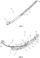
figure 3 shows a perspective view of the arm of the chain-tensioning rod offigure 1 ; and -
figure 4 shows a perspective view illustrating an assembly phase between arm and shoe of the previous figures. - By referring to figures, a chain-tensioning rod is designated as a whole with 1. It is of the type which is used in an internal combustion engine with overhead camshaft valvetrain, to keep tensioned the timing chain transferring the motion from a pinion connected to the crankshaft to another wheel, called crown, connected to the camshaft.
- In the present embodiment, the
rod 1 has an elongated shape extending between aproximal end 2, thereat therod 1 is hinged inside the engine, and adistal end 3. - The
rod 1 is substantially embodied by two distinct portions. A first portion relates to a shoe 4 (figure 2 ) generally made of a synthetic material, particularly of resin, allowing to implement a low friction with the outer surface of the transmission chain. - The
shoe 4 is pressed by an actuator (not shown) so that it exerts a pressure on the chain, thus by keeping it in tension. - The shoe is formed by a monolithic piece in resin, produced by injection moulding, and it has a smooth sliding
surface 5 at one exposed side of therod 1. Such surface can be delimited by longitudinalraised edges 11, which thus define a guide for the chain. - Along its extension, the
shoe 4 has acentral portion 12 with a larger width and twoend portions - On the opposite side, the
shoe 4 has a supportingsurface 6 thereat it is pressed by said actuator. The supportingsurface 6 substantially extends from theproximal end 2 to thedistal end 3 of therod 1. - To this purpose, in a central position, on such supporting
surface 6 it comprises acontact element 7 with a parallelepiped shape and a contact face 8 spaced apart and parallel to the supportingsurface 6. - It is to be noted that the
contact element 7 is not a solid block of material, but it has lighteningside grooves 9. - The
contact element 7 is supported in a raised position with respect to said supportingsurface 6, being connected thereto by means of a first connectingrib 10, longitudinally developing along the supportingsurface 6 and in a central position with respect thereto, rising perpendicularly and thus constituting the central core of thecontact element 7. - At the
proximal end 2, theshoe 4 comprises an eyelet-like portion 15 formed by two portions projecting from theproximal end portion 13. They form, respectively, aneyelet 16, with a circular opening the axis thereof is perpendicular to the development of therod 1, and acurved wall 17 representing the extension of the supportingsurface 6. - The
eyelet 16 is formed by a holed wall extending from a longitudinal margin of the supportingsurface 6 at theproximal end 2. - On the contrary, at the distal end of the
rod 1, theshoe 4 comprises a hook-like portion 18 formed by a wall which, extending from the supportingsurface 6, folds by 180° by forming arecess 19 between itself and the supportingsurface 6. - Said wall is further connected to the supporting
surface 6 by a second connectingrib 20, which, like the first one, longitudinally develops along the supportingsurface 6 and in a central position with respect thereto, perpendicularly rising and thus constituting the central core of the hook-like portion 18. - At the outer margins of the supporting
surface 6, theshoe 4 comprises stopping elements: edging tracts rising from said margins perpendicularly to thesurface 6. - In particular, the
shoe 4 comprises aproximal stopping element 21 on theproximal end portion 13, the position thereof is placed on the opposite margin with respect to the one whereon said eyelet-like portion 16 is placed. - The shoe described so far further comprises a pair of
distal stopping elements surface 6. Thesedistal stopping elements proximal stopping element 21 and the two connectingribs tensioning rod 1. - It is to be noted that all portions described so far in relation to the
shoe 4 are integral therewith and constitute one single monolithic piece. - The second one of said portions constituting the
rod 1 is then a supportingarm 25 which is formed by an elongated blade obtained from a curved band with substantially constant thickness, made of metal, for example harmonic steel. - Even the supporting arm 25 (
figure 3 ) is monolithic, obtained by punching and finishing from an unfinished metallic piece.
the supportingarm 25 in turn extends between the opposite ends and it comprises, at the proximal end, a ring-like shape 26 apt to couple with the eyelet-like portion 15 to form therewith a hinge element apt to be engaged by a (not represented) pin connected to the engine. - The
arm 25 then comprises a longitudinal pass-throughslit 27 extending from the distal end, wherein the slit is open, having then aninlet mouth 28, for at least half length of thearm 25. Theslit 27 extends between said distal end for at least half length of the supportingarm 25, so as to be able to extend from thedistal end 3 of the shoe as far as including the wholefirst rib 10 of thecontact element 7. - The
slit 27 has a constant width, it is positioned symmetrically in a central position with respect to thearm 25, and ends with a stoppingend 29. - The insertion of the supporting
arm 25 on the supportingsurface 6 of theshoe 4 takes place as shown infigure 4 . - The
arm 25 and theshoe 4 are overlapped, so that the extrados of thearm 25 is in contact with theproximal end portion 13 of theshoe 4. The overlapping takes place by making the supportingarm 25 to slide on the supportingsurface 6 from theproximal end 2 of therod 1, until the first connectingrib 10 of thecontact element 7 is inserted in the mouth of theslit 27 and it is made to slide as far as even thesecond rib 20 enters theslit 27. - As the sliding continues, the distal end of the
arm 25 inserts inside the hook-like portion 18 reaching the end thereof; furthermore, the stoppingend 29 of theslit 27 is in contact with thefirst rib 10 and, at last, thering 26 couples with the eyelet-like portion 15. - It is to be noted that, in this coupling process,
arm 25 andshoe 4 translate longitudinally one with respect to the other one, without having to resort to rotations of any type. - With this insertion, the first connecting
rib 10 acts as transversal and central locking device of thearm 25 on the supportingsurface 6 of theshoe 4.
Claims (12)
- A chain-tensioning rod (1), of the type used in an internal combustion engine with an overhead camshaft valvetrain to keep in tension a timing chain, comprising a shoe (4), which is pressed against the timing chain, and a supporting arm (25) of the shoe, characterized in that:• the shoe (4) is formed by a monolithic piece having, on one side thereof a sliding surface (5) and, on the opposite side, a supporting surface (6) and a contact element (7), which is connected to the supporting surface (6) at a central portion of the shoe (4) by means of a connecting rib (10) longitudinally developing along the supporting surface (6) and in the centre thereof, the supporting surface (6) extending from a proximal end (2), thereat the chain-tensioning rod is hinged, and a distal end (3);• the supporting arm (25) is formed by an elongated blade having a longitudinal pass-through slit (27) extending from a distal end thereof, wherein it is open, for at least half length of the supporting arm (25),so that the insertion of the supporting arm (25) on the supporting surface (6) takes place by making the supporting arm (25) to slide on the supporting surface (6) from said proximal end (2), by inserting said connecting rib (10) into said slit (27), the connecting rib (10) operating as a transversal locking device of the supporting arm (25) on the supporting surface (6).
- The chain-tensioning rod (1) according to claim 1, wherein the contact element (7) is supported in a raised position with respect to said supporting surface (6) from the connecting rib (10), which perpendicularly rises and constitutes the central core of the contact element (7).
- The chain-tensioning rod (1) according to claim 2, wherein the contact element (7) has a parallelepiped shape and a contact face (8) spaced apart and parallel to the supporting surface (6).
- The chain-tensioning rod (1) according to claim 1, wherein, at a proximal end thereof (2), the shoe (4) comprises an eyelet-like portion (15); and wherein the supporting arm (25) comprises, at said proximal end (2), a ring-like shape (26) apt to couple with the eyelet-like portion (15) to form therewith a hinge element apt to be engaged by a pin connected to the engine.
- The chain-tensioning rod (1) according to claim 4, wherein the eyelet-like portion (15) is formed by two portions projecting and forming (16), respectively, an eyelet, with a circular opening the axis thereof is perpendicular to the development of the chain-tensioning rod (1), and a curved wall (17) representing the extension of the supporting surface (6), the eyelet 16 being formed by a holed wall extending from a longitudinal margin of the supporting surface (6) at the proximal end (2).
- The chain-tensioning rod (1) according to claim 1, wherein, at a distal end (3) of the chain-tensioning rod (1), the shoe (4) comprises a hook-like portion (18) formed by a wall which, extending from the supporting surface (6), folds by 180° by forming a recess (19) between itself and the supporting surface (6).
- The chain-tensioning rod (1) according to claim 6, wherein the hook-like portion (18) is connected to the supporting surface (6) by an additional longitudinal and central connecting rib (20), apt to be inserted in said slit (27) of the supporting arm (25).
- The chain-tensioning rod (1) according to claim 1, wherein, at the outer margins of the supporting surface (6), the shoe (4) comprises stopping elements formed by edging tracts rising from said margins perpendicularly to the supporting surface (6).
- The chain-tensioning rod (1) according to claims 5 and 8, wherein the shoe (4) comprises a proximal stopping element (21) on its own proximal end portion (13), the position thereof is placed on the opposite margin with respect to that thereon said eyelet-like shape (16) is placed.
- The chain-tensioning rod (1) according to claim 8, wherein the shoe (4) comprises a pair of distal stopping elements (22, 23), arranged on opposite margins of the supporting surface (6), staggered therebetween.
- The chain-tensioning rod (1) according to claim 1, wherein the slit (27) has a constant width, it is positioned symmetrically in central position with respect to the supporting arm (25), and ends with a stopping end (29) which comes in contact with said rib (10).
- The chain-tensioning rod (1) according to claim 1, wherein said supporting arm (25) is made of metal, for example harmonic steel.
Applications Claiming Priority (3)
| Application Number | Priority Date | Filing Date | Title |
|---|---|---|---|
| ITRM20140450 | 2014-08-01 | ||
| ITRM20140451 | 2014-08-01 | ||
| PCT/IB2015/055766 WO2016016836A2 (en) | 2014-08-01 | 2015-07-30 | Chain-tensioning rod |
Publications (2)
| Publication Number | Publication Date |
|---|---|
| EP3175144A2 EP3175144A2 (en) | 2017-06-07 |
| EP3175144B1 true EP3175144B1 (en) | 2018-10-17 |
Family
ID=54062777
Family Applications (1)
| Application Number | Title | Priority Date | Filing Date |
|---|---|---|---|
| EP15759543.0A Active EP3175144B1 (en) | 2014-08-01 | 2015-07-30 | Chain-tensioning rod |
Country Status (6)
| Country | Link |
|---|---|
| US (1) | US10408311B2 (en) |
| EP (1) | EP3175144B1 (en) |
| JP (1) | JP6535729B2 (en) |
| CN (1) | CN106536982B (en) |
| ES (1) | ES2702283T3 (en) |
| WO (1) | WO2016016836A2 (en) |
Families Citing this family (3)
| Publication number | Priority date | Publication date | Assignee | Title |
|---|---|---|---|---|
| CN107981858B (en) | 2017-11-27 | 2020-12-01 | 上海优加利健康管理有限公司 | Automatic electrocardiogram heart beat identification and classification method based on artificial intelligence |
| JP7277732B2 (en) * | 2019-05-15 | 2023-05-19 | 株式会社椿本チエイン | tensioner lever |
| US11815180B2 (en) * | 2021-08-24 | 2023-11-14 | Schaeffler Technologies AG & Co. KG | Tensioner with stamped pivot pin |
Family Cites Families (13)
| Publication number | Priority date | Publication date | Assignee | Title |
|---|---|---|---|---|
| US4921472A (en) * | 1989-06-12 | 1990-05-01 | Borg-Warner Automotive Transmission & Engine Components Corporation | Chain tensioner |
| JPH089476Y2 (en) | 1991-11-07 | 1996-03-21 | 株式会社椿本チエイン | Integrated structure of chain guide arm and shoe |
| GB0020908D0 (en) * | 2000-08-25 | 2000-10-11 | Renold Plc | Chain or belt tensioner |
| US6623391B2 (en) * | 2000-10-17 | 2003-09-23 | Cloyes Gear And Products, Inc. | Blade-type mechanical chain tensioner with external strengthening rib |
| JP3550548B2 (en) * | 2001-02-02 | 2004-08-04 | ボルグワーナー・モールステック・ジャパン株式会社 | Clip for blade spring and blade tensioner provided with the clip |
| JP3532179B2 (en) | 2001-10-31 | 2004-05-31 | 本田技研工業株式会社 | Cam chain tensioner |
| JP3359340B1 (en) * | 2002-01-23 | 2002-12-24 | 株式会社椿本チエイン | Movable guide for transmission |
| JP4312107B2 (en) * | 2004-06-15 | 2009-08-12 | 株式会社椿本チエイン | Synthetic resin guide for transmission |
| JP2009103186A (en) | 2007-10-22 | 2009-05-14 | Tsubakimoto Chain Co | Guide for transmission |
| JP2013164134A (en) * | 2012-02-10 | 2013-08-22 | Tsubakimoto Chain Co | Chain guide for transmission device |
| DE102012206664B4 (en) * | 2012-04-23 | 2016-01-14 | Schaeffler Technologies AG & Co. KG | Mechanical chain tensioning unit with spring band steel support body and wedge adjusting device |
| JP5980177B2 (en) * | 2013-07-22 | 2016-08-31 | 株式会社椿本チエイン | Chain guide |
| JP6539244B2 (en) * | 2016-09-30 | 2019-07-03 | 本田技研工業株式会社 | Internal combustion engine |
-
2015
- 2015-07-30 EP EP15759543.0A patent/EP3175144B1/en active Active
- 2015-07-30 WO PCT/IB2015/055766 patent/WO2016016836A2/en active Application Filing
- 2015-07-30 CN CN201580035194.1A patent/CN106536982B/en active Active
- 2015-07-30 US US15/320,939 patent/US10408311B2/en active Active
- 2015-07-30 JP JP2017503891A patent/JP6535729B2/en active Active
- 2015-07-30 ES ES15759543T patent/ES2702283T3/en active Active
Non-Patent Citations (1)
| Title |
|---|
| None * |
Also Published As
| Publication number | Publication date |
|---|---|
| ES2702283T3 (en) | 2019-02-28 |
| US10408311B2 (en) | 2019-09-10 |
| CN106536982B (en) | 2019-06-04 |
| US20170152923A1 (en) | 2017-06-01 |
| JP2017524104A (en) | 2017-08-24 |
| JP6535729B2 (en) | 2019-06-26 |
| WO2016016836A3 (en) | 2016-03-24 |
| CN106536982A (en) | 2017-03-22 |
| WO2016016836A2 (en) | 2016-02-04 |
| EP3175144A2 (en) | 2017-06-07 |
Similar Documents
| Publication | Publication Date | Title |
|---|---|---|
| EP3175144B1 (en) | Chain-tensioning rod | |
| KR101471701B1 (en) | Chain guide mechanism | |
| US8789245B2 (en) | Extensible clasp for a wrist strap in particular of a watch | |
| JP6975218B2 (en) | Adjustable band Nakadome | |
| KR20110049714A (en) | Chain guide mechanism | |
| US8601784B2 (en) | Anti-rotation link | |
| US7951029B2 (en) | Guide for transmission device | |
| RU2650915C9 (en) | Bracelet clasp comprising device for adjusting useful length of the bracelet | |
| US20130160736A1 (en) | Intake air flow control valve | |
| JP2007160572A (en) | Binding implement of document or the like | |
| BRPI0820489B1 (en) | belt profile and patterned belt | |
| JP6906840B2 (en) | Chain guide mechanism | |
| ITTO930827A1 (en) | CLAMP, IN PARTICULAR CLAMP FOR FLEXIBLE HOSES | |
| JP5797685B2 (en) | Loose leaf binding | |
| US20090089980A1 (en) | Device for the fine adjustment of the useful length of a wrist strap, such as the wrist strap of a watch | |
| BRPI1106248B1 (en) | chain tensioning device | |
| EP1716776A2 (en) | Device for adjusting the length of a bracelet provided with a foldable fastener | |
| ITTV20060086A1 (en) | ARPIONISM DEVICE, IN PARTICULAR FOR FOOTWEAR | |
| JP5681561B2 (en) | Chain tensioner device | |
| JP7378537B2 (en) | Wristlet clasp with length adjustment | |
| JP2007064121A (en) | Internal combustion engine | |
| JPWO2021153268A5 (en) | ||
| KR200395796Y1 (en) | string for opening and shutting fixed body for vinyl house | |
| CH249201A (en) | Watch strap. | |
| ITBS20130023U1 (en) | SUPPORT FRAME FOR FILTERS |
Legal Events
| Date | Code | Title | Description |
|---|---|---|---|
| STAA | Information on the status of an ep patent application or granted ep patent |
Free format text: STATUS: THE INTERNATIONAL PUBLICATION HAS BEEN MADE |
|
| 17P | Request for examination filed |
Effective date: 20161219 |
|
| AK | Designated contracting states |
Kind code of ref document: A2 Designated state(s): AL AT BE BG CH CY CZ DE DK EE ES FI FR GB GR HR HU IE IS IT LI LT LU LV MC MK MT NL NO PL PT RO RS SE SI SK SM TR |
|
| AX | Request for extension of the european patent |
Extension state: BA ME |
|
| PUAI | Public reference made under article 153(3) epc to a published international application that has entered the european phase |
Free format text: ORIGINAL CODE: 0009012 |
|
| STAA | Information on the status of an ep patent application or granted ep patent |
Free format text: STATUS: REQUEST FOR EXAMINATION WAS MADE |
|
| DAV | Request for validation of the european patent (deleted) | ||
| DAX | Request for extension of the european patent (deleted) | ||
| GRAP | Despatch of communication of intention to grant a patent |
Free format text: ORIGINAL CODE: EPIDOSNIGR1 |
|
| STAA | Information on the status of an ep patent application or granted ep patent |
Free format text: STATUS: GRANT OF PATENT IS INTENDED |
|
| INTG | Intention to grant announced |
Effective date: 20180503 |
|
| GRAS | Grant fee paid |
Free format text: ORIGINAL CODE: EPIDOSNIGR3 |
|
| GRAA | (expected) grant |
Free format text: ORIGINAL CODE: 0009210 |
|
| STAA | Information on the status of an ep patent application or granted ep patent |
Free format text: STATUS: THE PATENT HAS BEEN GRANTED |
|
| AK | Designated contracting states |
Kind code of ref document: B1 Designated state(s): AL AT BE BG CH CY CZ DE DK EE ES FI FR GB GR HR HU IE IS IT LI LT LU LV MC MK MT NL NO PL PT RO RS SE SI SK SM TR |
|
| REG | Reference to a national code |
Ref country code: GB Ref legal event code: FG4D |
|
| REG | Reference to a national code |
Ref country code: CH Ref legal event code: EP |
|
| REG | Reference to a national code |
Ref country code: IE Ref legal event code: FG4D |
|
| REG | Reference to a national code |
Ref country code: DE Ref legal event code: R096 Ref document number: 602015018388 Country of ref document: DE Ref country code: AT Ref legal event code: REF Ref document number: 1054423 Country of ref document: AT Kind code of ref document: T Effective date: 20181115 |
|
| REG | Reference to a national code |
Ref country code: NL Ref legal event code: MP Effective date: 20181017 |
|
| REG | Reference to a national code |
Ref country code: ES Ref legal event code: FG2A Ref document number: 2702283 Country of ref document: ES Kind code of ref document: T3 Effective date: 20190228 |
|
| REG | Reference to a national code |
Ref country code: LT Ref legal event code: MG4D |
|
| PG25 | Lapsed in a contracting state [announced via postgrant information from national office to epo] |
Ref country code: NL Free format text: LAPSE BECAUSE OF FAILURE TO SUBMIT A TRANSLATION OF THE DESCRIPTION OR TO PAY THE FEE WITHIN THE PRESCRIBED TIME-LIMIT Effective date: 20181017 |
|
| REG | Reference to a national code |
Ref country code: GR Ref legal event code: EP Ref document number: 20180403828 Country of ref document: GR Effective date: 20190422 |
|
| PG25 | Lapsed in a contracting state [announced via postgrant information from national office to epo] |
Ref country code: HR Free format text: LAPSE BECAUSE OF FAILURE TO SUBMIT A TRANSLATION OF THE DESCRIPTION OR TO PAY THE FEE WITHIN THE PRESCRIBED TIME-LIMIT Effective date: 20181017 Ref country code: LT Free format text: LAPSE BECAUSE OF FAILURE TO SUBMIT A TRANSLATION OF THE DESCRIPTION OR TO PAY THE FEE WITHIN THE PRESCRIBED TIME-LIMIT Effective date: 20181017 Ref country code: PL Free format text: LAPSE BECAUSE OF FAILURE TO SUBMIT A TRANSLATION OF THE DESCRIPTION OR TO PAY THE FEE WITHIN THE PRESCRIBED TIME-LIMIT Effective date: 20181017 Ref country code: BG Free format text: LAPSE BECAUSE OF FAILURE TO SUBMIT A TRANSLATION OF THE DESCRIPTION OR TO PAY THE FEE WITHIN THE PRESCRIBED TIME-LIMIT Effective date: 20190117 Ref country code: NO Free format text: LAPSE BECAUSE OF FAILURE TO SUBMIT A TRANSLATION OF THE DESCRIPTION OR TO PAY THE FEE WITHIN THE PRESCRIBED TIME-LIMIT Effective date: 20190117 Ref country code: IS Free format text: LAPSE BECAUSE OF FAILURE TO SUBMIT A TRANSLATION OF THE DESCRIPTION OR TO PAY THE FEE WITHIN THE PRESCRIBED TIME-LIMIT Effective date: 20190217 Ref country code: FI Free format text: LAPSE BECAUSE OF FAILURE TO SUBMIT A TRANSLATION OF THE DESCRIPTION OR TO PAY THE FEE WITHIN THE PRESCRIBED TIME-LIMIT Effective date: 20181017 Ref country code: LV Free format text: LAPSE BECAUSE OF FAILURE TO SUBMIT A TRANSLATION OF THE DESCRIPTION OR TO PAY THE FEE WITHIN THE PRESCRIBED TIME-LIMIT Effective date: 20181017 |
|
| PG25 | Lapsed in a contracting state [announced via postgrant information from national office to epo] |
Ref country code: RS Free format text: LAPSE BECAUSE OF FAILURE TO SUBMIT A TRANSLATION OF THE DESCRIPTION OR TO PAY THE FEE WITHIN THE PRESCRIBED TIME-LIMIT Effective date: 20181017 Ref country code: AL Free format text: LAPSE BECAUSE OF FAILURE TO SUBMIT A TRANSLATION OF THE DESCRIPTION OR TO PAY THE FEE WITHIN THE PRESCRIBED TIME-LIMIT Effective date: 20181017 Ref country code: SE Free format text: LAPSE BECAUSE OF FAILURE TO SUBMIT A TRANSLATION OF THE DESCRIPTION OR TO PAY THE FEE WITHIN THE PRESCRIBED TIME-LIMIT Effective date: 20181017 Ref country code: PT Free format text: LAPSE BECAUSE OF FAILURE TO SUBMIT A TRANSLATION OF THE DESCRIPTION OR TO PAY THE FEE WITHIN THE PRESCRIBED TIME-LIMIT Effective date: 20190217 |
|
| REG | Reference to a national code |
Ref country code: DE Ref legal event code: R097 Ref document number: 602015018388 Country of ref document: DE |
|
| PG25 | Lapsed in a contracting state [announced via postgrant information from national office to epo] |
Ref country code: DK Free format text: LAPSE BECAUSE OF FAILURE TO SUBMIT A TRANSLATION OF THE DESCRIPTION OR TO PAY THE FEE WITHIN THE PRESCRIBED TIME-LIMIT Effective date: 20181017 Ref country code: IT Free format text: LAPSE BECAUSE OF FAILURE TO SUBMIT A TRANSLATION OF THE DESCRIPTION OR TO PAY THE FEE WITHIN THE PRESCRIBED TIME-LIMIT Effective date: 20181017 Ref country code: CZ Free format text: LAPSE BECAUSE OF FAILURE TO SUBMIT A TRANSLATION OF THE DESCRIPTION OR TO PAY THE FEE WITHIN THE PRESCRIBED TIME-LIMIT Effective date: 20181017 |
|
| PLBE | No opposition filed within time limit |
Free format text: ORIGINAL CODE: 0009261 |
|
| STAA | Information on the status of an ep patent application or granted ep patent |
Free format text: STATUS: NO OPPOSITION FILED WITHIN TIME LIMIT |
|
| PG25 | Lapsed in a contracting state [announced via postgrant information from national office to epo] |
Ref country code: RO Free format text: LAPSE BECAUSE OF FAILURE TO SUBMIT A TRANSLATION OF THE DESCRIPTION OR TO PAY THE FEE WITHIN THE PRESCRIBED TIME-LIMIT Effective date: 20181017 Ref country code: EE Free format text: LAPSE BECAUSE OF FAILURE TO SUBMIT A TRANSLATION OF THE DESCRIPTION OR TO PAY THE FEE WITHIN THE PRESCRIBED TIME-LIMIT Effective date: 20181017 Ref country code: SM Free format text: LAPSE BECAUSE OF FAILURE TO SUBMIT A TRANSLATION OF THE DESCRIPTION OR TO PAY THE FEE WITHIN THE PRESCRIBED TIME-LIMIT Effective date: 20181017 Ref country code: SK Free format text: LAPSE BECAUSE OF FAILURE TO SUBMIT A TRANSLATION OF THE DESCRIPTION OR TO PAY THE FEE WITHIN THE PRESCRIBED TIME-LIMIT Effective date: 20181017 |
|
| 26N | No opposition filed |
Effective date: 20190718 |
|
| PG25 | Lapsed in a contracting state [announced via postgrant information from national office to epo] |
Ref country code: SI Free format text: LAPSE BECAUSE OF FAILURE TO SUBMIT A TRANSLATION OF THE DESCRIPTION OR TO PAY THE FEE WITHIN THE PRESCRIBED TIME-LIMIT Effective date: 20181017 |
|
| PG25 | Lapsed in a contracting state [announced via postgrant information from national office to epo] |
Ref country code: MC Free format text: LAPSE BECAUSE OF FAILURE TO SUBMIT A TRANSLATION OF THE DESCRIPTION OR TO PAY THE FEE WITHIN THE PRESCRIBED TIME-LIMIT Effective date: 20181017 |
|
| REG | Reference to a national code |
Ref country code: CH Ref legal event code: PL |
|
| PG25 | Lapsed in a contracting state [announced via postgrant information from national office to epo] |
Ref country code: TR Free format text: LAPSE BECAUSE OF FAILURE TO SUBMIT A TRANSLATION OF THE DESCRIPTION OR TO PAY THE FEE WITHIN THE PRESCRIBED TIME-LIMIT Effective date: 20181017 |
|
| REG | Reference to a national code |
Ref country code: BE Ref legal event code: MM Effective date: 20190731 |
|
| PG25 | Lapsed in a contracting state [announced via postgrant information from national office to epo] |
Ref country code: BE Free format text: LAPSE BECAUSE OF NON-PAYMENT OF DUE FEES Effective date: 20190731 Ref country code: LI Free format text: LAPSE BECAUSE OF NON-PAYMENT OF DUE FEES Effective date: 20190731 Ref country code: LU Free format text: LAPSE BECAUSE OF NON-PAYMENT OF DUE FEES Effective date: 20190730 Ref country code: CH Free format text: LAPSE BECAUSE OF NON-PAYMENT OF DUE FEES Effective date: 20190731 |
|
| PG25 | Lapsed in a contracting state [announced via postgrant information from national office to epo] |
Ref country code: IE Free format text: LAPSE BECAUSE OF NON-PAYMENT OF DUE FEES Effective date: 20190730 |
|
| PG25 | Lapsed in a contracting state [announced via postgrant information from national office to epo] |
Ref country code: CY Free format text: LAPSE BECAUSE OF FAILURE TO SUBMIT A TRANSLATION OF THE DESCRIPTION OR TO PAY THE FEE WITHIN THE PRESCRIBED TIME-LIMIT Effective date: 20181017 |
|
| PG25 | Lapsed in a contracting state [announced via postgrant information from national office to epo] |
Ref country code: MT Free format text: LAPSE BECAUSE OF FAILURE TO SUBMIT A TRANSLATION OF THE DESCRIPTION OR TO PAY THE FEE WITHIN THE PRESCRIBED TIME-LIMIT Effective date: 20181017 Ref country code: HU Free format text: LAPSE BECAUSE OF FAILURE TO SUBMIT A TRANSLATION OF THE DESCRIPTION OR TO PAY THE FEE WITHIN THE PRESCRIBED TIME-LIMIT; INVALID AB INITIO Effective date: 20150730 |
|
| REG | Reference to a national code |
Ref country code: AT Ref legal event code: UEP Ref document number: 1054423 Country of ref document: AT Kind code of ref document: T Effective date: 20181017 |
|
| PG25 | Lapsed in a contracting state [announced via postgrant information from national office to epo] |
Ref country code: MK Free format text: LAPSE BECAUSE OF FAILURE TO SUBMIT A TRANSLATION OF THE DESCRIPTION OR TO PAY THE FEE WITHIN THE PRESCRIBED TIME-LIMIT Effective date: 20181017 |
|
| PGFP | Annual fee paid to national office [announced via postgrant information from national office to epo] |
Ref country code: AT Payment date: 20220627 Year of fee payment: 8 |
|
| P01 | Opt-out of the competence of the unified patent court (upc) registered |
Effective date: 20230525 |
|
| PGFP | Annual fee paid to national office [announced via postgrant information from national office to epo] |
Ref country code: FR Payment date: 20230608 Year of fee payment: 9 |
|
| PGFP | Annual fee paid to national office [announced via postgrant information from national office to epo] |
Ref country code: GR Payment date: 20230613 Year of fee payment: 9 |
|
| PGFP | Annual fee paid to national office [announced via postgrant information from national office to epo] |
Ref country code: GB Payment date: 20230608 Year of fee payment: 9 Ref country code: ES Payment date: 20230810 Year of fee payment: 9 |
|
| PGFP | Annual fee paid to national office [announced via postgrant information from national office to epo] |
Ref country code: DE Payment date: 20230607 Year of fee payment: 9 |
|
| REG | Reference to a national code |
Ref country code: AT Ref legal event code: MM01 Ref document number: 1054423 Country of ref document: AT Kind code of ref document: T Effective date: 20230730 |
|
| PG25 | Lapsed in a contracting state [announced via postgrant information from national office to epo] |
Ref country code: AT Free format text: LAPSE BECAUSE OF NON-PAYMENT OF DUE FEES Effective date: 20230730 |