EP1441149A1 - Cam chain tensioner - Google Patents
Cam chain tensioner Download PDFInfo
- Publication number
- EP1441149A1 EP1441149A1 EP02760831A EP02760831A EP1441149A1 EP 1441149 A1 EP1441149 A1 EP 1441149A1 EP 02760831 A EP02760831 A EP 02760831A EP 02760831 A EP02760831 A EP 02760831A EP 1441149 A1 EP1441149 A1 EP 1441149A1
- Authority
- EP
- European Patent Office
- Prior art keywords
- arm
- shoe
- end part
- timing chain
- resin shoe
- Prior art date
- Legal status (The legal status is an assumption and is not a legal conclusion. Google has not performed a legal analysis and makes no representation as to the accuracy of the status listed.)
- Granted
Links
Images



Classifications
-
- F—MECHANICAL ENGINEERING; LIGHTING; HEATING; WEAPONS; BLASTING
- F16—ENGINEERING ELEMENTS AND UNITS; GENERAL MEASURES FOR PRODUCING AND MAINTAINING EFFECTIVE FUNCTIONING OF MACHINES OR INSTALLATIONS; THERMAL INSULATION IN GENERAL
- F16H—GEARING
- F16H7/00—Gearings for conveying rotary motion by endless flexible members
- F16H7/08—Means for varying tension of belts, ropes or chains
-
- F—MECHANICAL ENGINEERING; LIGHTING; HEATING; WEAPONS; BLASTING
- F16—ENGINEERING ELEMENTS AND UNITS; GENERAL MEASURES FOR PRODUCING AND MAINTAINING EFFECTIVE FUNCTIONING OF MACHINES OR INSTALLATIONS; THERMAL INSULATION IN GENERAL
- F16H—GEARING
- F16H7/00—Gearings for conveying rotary motion by endless flexible members
- F16H7/08—Means for varying tension of belts, ropes or chains
- F16H2007/0802—Actuators for final output members
- F16H2007/0804—Leaf springs
-
- F—MECHANICAL ENGINEERING; LIGHTING; HEATING; WEAPONS; BLASTING
- F16—ENGINEERING ELEMENTS AND UNITS; GENERAL MEASURES FOR PRODUCING AND MAINTAINING EFFECTIVE FUNCTIONING OF MACHINES OR INSTALLATIONS; THERMAL INSULATION IN GENERAL
- F16H—GEARING
- F16H7/00—Gearings for conveying rotary motion by endless flexible members
- F16H7/08—Means for varying tension of belts, ropes or chains
- F16H2007/0863—Finally actuated members, e.g. constructional details thereof
- F16H2007/0872—Sliding members
-
- F—MECHANICAL ENGINEERING; LIGHTING; HEATING; WEAPONS; BLASTING
- F16—ENGINEERING ELEMENTS AND UNITS; GENERAL MEASURES FOR PRODUCING AND MAINTAINING EFFECTIVE FUNCTIONING OF MACHINES OR INSTALLATIONS; THERMAL INSULATION IN GENERAL
- F16H—GEARING
- F16H7/00—Gearings for conveying rotary motion by endless flexible members
- F16H7/18—Means for guiding or supporting belts, ropes, or chains
- F16H2007/185—Means for guiding or supporting belts, ropes, or chains the guiding surface in contact with the belt, rope or chain having particular shapes, structures or materials
Definitions
- the present invention relates to a timing chain tensioning device for a valve mechanism included in an OHC internal combustion engine for a vehicle or the like.
- Fig. 11 is an exploded perspective view of a prior art timing chain tensioning device 001 disclosed in JP-A No. 42798/1993.
- the timing chain tensioning device 001 includes an arm 002 of a metal, a shoe 003 of a resin extended on the front surface of the arm 002, and a pad 004 of a resin connected to a middle lower part of the arm 002.
- Fig. 12 is a cross-sectional view of a part including the pad 004 of the assembled timing chain tensioning device 001.
- the arm 002 is formed of a metal, such as aluminum, and has a base end part 002a provided with a hole 002b in which an attaching bolt is inserted.
- a groove 003a of a width substantially equal to the width of a timing chain is formed in a working surface of the shoe 003 to be attached to the arm 002.
- the groove 003a is defined by a bottom surface along which a timing chain slides, and low opposite side walls 003b.
- Joining legs are formed in a base end part 003c of the shoe 003.
- the base end part 002a of the arm 002 is disposed between the joining legs respectively provided with slots 003d of the base end part 003c of the shoe 003.
- the attaching bolt is passed through the slots 003d of the shoe 003 and the hole 002b of the arm 002 to fastened the base end part 002a of the arm 002 and the base end part 003c of the shoe 003 together.
- a free end part of the shoe 003 is bent to form a U-shaped hook 003e, which is engaged with a free end part of the arm 002.
- a locating protrusion 003f is formed in a middle part of the shoe 003.
- the locating protrusion 003f is fitted in a recess 002c formed in the arm 002 to locate the shoe 003 correctly on the arm 002.
- the pad 004 is connected to the back surface, i.e., a surface opposite to the front surface to face the timing chain of the arm 002.
- the pad 004 serves as a sound absorbing member that absorbs an attack sound generated when a projection of a tensioner lifter strikes against the arm 002.
- the pad 004 serving as a sound absorbing member of this timing chain tensioning device is attached to the arm 002 by fitting a part thereof in a corresponding opening formed in the arm 002, many other arms are provided with a back rubber member attached thereto by baking.
- the joining legs of the base end part of the shoe extends on the opposite sides of the base end part of the arm. Therefore, an additional machining time is necessary for forming the joining legs of the shoe. Since the prior art timing chain tensioning device has the pad 004 put on the back surface of the arm 002 or the back rubber member joined to the arm by baking, additional parts, work time and labor are necessary for manufacturing the pad and putting the pad on the arm or attaching the back rubber member to the arm by baking.
- the present invention provides means capable of replacing members and work necessary for manufacturing the prior art timing chain tensioning device and it is an object of the present invention to provide a timing chain tensioning device comprising a reduced number of members, capable of being manufactured by reduced man-hours and reduced steps.
- the present invention provides a timing chain tensioning device including: an arm having an attaching part formed in its base end part; and a resin shoe mounted on the arm so as to extend along the arm and to be brought into sliding contact with a chain; wherein a U-shaped hook that engages a free end part of the arm is formed in a free end part of the resin shoe, a side lug is extended from one side of a base end part of the resin shoe so as to correspond to the attaching part of the arm.
- the side lug of the base end part of the resin shoe is provided with an opening for use in fastening the attaching part of the arm and the base end part of the resin shoe together, and a cushioning pad having a U-shaped cross section with which a tensioner lifter comes into contact is formed in a substantially middle part of the resin shoe so as to extend along one of the sides of the arm to the back surface of the arm.
- the timing chain tensioning device of the present invention thus constructed, only the side lug of the base end part of the resin shoe is extended so as to correspond to the attaching part of the arm, and is fastened together with the attaching part of the arm, and the side lug of the base end part of the resin shoe is provided with the opening.
- the resin shoe can be easily manufactured and facilitates attaching work.
- a substantially middle part of the shoe is extended so as to extend around the side edges of the arm to the back side of the arm to form the part of the shoe is used as a cushioning member. Therefore, the timing chain tensioning device needs a small number of parts and facilitates attaching a cushioning member.
- the U-shaped hook and the cushioning pad are formed integrally with the resin shoe.
- the U-shaped hook has a U-shaped cross section and is provided on its inner side surface with a positioning projection for determining the lateral position of the resin shoe relative to the arm.
- the cushioning pad is provided on its inner side surface with a positioning projection for determining the lateral position of the resin shoe relative to the arm.
- the resin shoe may be provided with a positioning leg for determining the lateral position of the resin shoe relative to the arm in a part thereof near a middle part of thereof.
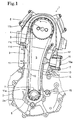
- Fig. 1 is a cutaway front elevation of a part including a timing chain of an OHC internal combustion engine 1 provided with a timing chain tensioning device in a preferred embodiment of the present invention for a motorcycle.
- the internal combustion engine 1 is assembled by placing a crankcase 2, a cylinder block 3 and a cylinder head 4 in that order one upon another.
- a chain chamber 5 is extended along the crankcase 2, the cylinder block 3 and the cylinder head 4.
- the internal combustion engine 1 shown in Fig. 1 is not provided with any cylinder head cover because the cylinder head 4 is divided longitudinally into two parts.
- crankshaft 6 projects into a section corresponding to the crankcase 2 of the chain chamber 5, and a drive sprocket 7 is mounted on the end part of the crankshaft 6.
- camshaft 8 projects into a section corresponding to the cylinder head 4 of the chain chamber 5.
- a driven sprocket 9 is mounted on the end part of the camshaft 8.
- a timing chain 10 is extended between the drive sprocket 7 and the driven sprocket 9. The drive sprocket 7 drives the driven sprocket 9 for rotation in the direction of the arrow through the timing chain 10 to rotate cams, not shown, formed on the camshaft 8.
- a timing chain guide 11 of a resin is extended along the tight side pulled by the drive sprocket 7 of the timing chain 10.
- the timing chain guide 11 has one end part extending from a bend 11a is inserted in a recess formed in a support 2a formed on a part in the chain chamber 5 of the crankcase 2, and the other end part 11b is free.
- the timing chain guide 11 has an attaching part 11c in a part near the other end part 11b.
- the timing chain guide 11 is supported on the cylinder block 3 by a pin 11d.
- the timing chain guide 11 has a substantially straight guide part having a bottom wall and low side walls on the opposite sides of the bottom wall. The bottom wall and the side walls define a groove.
- the timing chain 10 slides along the surface of the bottom wall. The side walls prevent the timing chain 10 from running off the chain guide 11.
- a timing chain tensioning device 12 in a preferred embodiment according to the present invention is pressed against the slack side extending between the push side of the drive sprocket 7 and the driven sprocket of the timing chain 10 by a hydraulic tensioner lifter 16 to take up a slack in the slack side of the timing chain 10.
- the tensioner lifter 16 is paced in the chain chamber 5 and is fastened to the outer surface of the cylinder block 3 with bolts 17.
- the tensioner lifter 16 is provided with a rod 16a pushed by hydraulic pressure so as to project into the chain chamber 5.
- the timing chain tensioning device 12 includes an arm 13 formed of a highly elastic steel, and a resin shoe 14 attached to a surface facing the timing chain 10 of the arm 13. A base end part of the arm 13, and a side lug 14c of a base end part of the shoe 14 of the timing chain tensioning device 12 on the side of the drive sprocket 7 are fastened together to the crankcase 2 with a bolt 15.
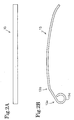
- Fig. 2A is a plan view of the arm 13 of the timing chain tensioning device 12, and Fig. 2B is a side elevation of the arm 13.
- the arm 13 is formed by curving a strip of a highly elastic steel, such as a spring steel.
- the base end part 13a of the arm 13 extends from a bend 13b and is curled in a ring 13c.
- the bolt 15 is passed through the ring 13c.
- Fig. 3 is a side elevation f the shoe 14 of the timing chain tensioning device 12
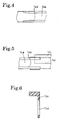
- Figs. 4 and 5 are enlarged views of parts of the shoe 14 taken in the directions of the arrows IV and V, respectively, in Fig. 3
- Figs. 6, 7, 8 and 9 are enlarged sectional views taken on lines VI-VI, VII-VII, VIII-VIII and IX-IX, respectively, in Fig. 3.
- the shoe 14 is a monolithic structure formed of a hard synthetic rubber in a shape conforming to the arm 13.
- a groove 14a of a width approximately equal to the width of the timing chain 10 is formed in a working side of the shoe 14.
- the shoe 14 has a bottom wall and low side walls 14b on the opposite sides of the bottom wall.
- the bottom wall and the side walls 14b define the groove 14a.
- the timing chain 10 slides along the surface of the bottom wall.
- the side walls 14b prevent the timing chain 10 from running off the chain guide 11.
- a side lug 14c provided with an opening 14d extends from one side of the base end part of the shoe 14 so as to extend along and correspond to the ring 13a of the arm 13.
- the shoe 14 is provided in a part on the side of the base end part with respect to a middle part thereof with a positioning leg 14e.
- the positioning leg 14e is formed integrally with the shoe 14.
- the positioning leg 14e comes into contact with one of the sides of the arm 13 to determine the lateral position of the shoe 14 relative to the arm 13.
- the shoe 14 is provided in a part on the side of the free end with respect to the middle part thereof with a U-shaped arm 14f extending along the other side of the shoe 14 to a part serving as a contact pad 14g on the back side of the shoe 14 corresponding to the tensioner lifter 16.
- the arm 14f is formed integrally with the shoe 14.
- a positioning projection 14h is formed on the inner surface of a side part of the U-shaped arm 14f. As shown in Fig. 3, a free end part of the arm 13 is bent in a U-shape to form a hook 14i. The hook 14i has a side part 14j on the same side as the positioning leg 14e. Thus, the free end part of the shoe 14 has a U-shaped cross section. A positioning projection 14k is formed on the inner surface of the side part 14j.
- Fig. 10 shows the base end part of the timing chain tensioning device 12 formed by assembling the arm 13 and the shoe 14.
- the timing chain tensioning device 12 is incorporated into the internal combustion engine
- the free end part of the arm 13 is inserted laterally in a groove formed in the U-shaped arm 14f of the shoe 14.
- the free end part of the arm 13 is pressed in the hook 14i of the show 14.
- the corresponding surfaces of the arm 13 and the shoe 14 come into contact with each other.
- the lateral position of the shoe 14 relative to the arm 13 is determined by the positioning lug 14e and the positioning projections 14h and 14k.
- the arm 13 can be easily formed by bending a metal strip in a short processing time.
- the lateral position of the show 14 relative to the arm 13 is determined by the positioning lug 14e and the positioning projections 14h and 14k, and the shoe 14 is held on the arm 13 without using any adhesive by engaging the hook 14i with the free end of the arm 13 and fastening the side lug 14c to the ring 13c of the arm 13 with the bolt 15.
- the timing chain tensioning device requires reduced man-hours for assembling. Since the side lug 14c extends only on one side of the shoe 14, the shoe 14, as compared with a shoe provided with side lugs on the opposite sides thereof, can be easily manufactured and combined with the arm 13. Since the cushioning pad 14g serving as a cushioning member is formed integrally with the shoe 14, the number of parts is reduced and additional man-hours for manufacturing, attaching and baking a separate cushioning member are unnecessary.
Landscapes
- Engineering & Computer Science (AREA)
- General Engineering & Computer Science (AREA)
- Mechanical Engineering (AREA)
- Devices For Conveying Motion By Means Of Endless Flexible Members (AREA)
- Valve-Gear Or Valve Arrangements (AREA)
- Valve Device For Special Equipments (AREA)
Abstract
Description
Claims (5)
- A timing chain tensioning device comprising: an arm (13) having an attaching part formed in its base end part; and a resin shoe (14) mounted on the arm (14) so as to extend along the arm (14) and to be brought into sliding contact with a chain (10);
characterized in that a U-shaped hook (14i) that engages a free end part of the arm (13) is formed in a free end part of the resin shoe (14), a side lug (14c) is extended from one side of a base end part of the resin shoe (14) so as to correspond to the attaching part of the arm (13), the side lug (14c) of the base end part of the resin shoe (14) is provided with an opening (14d) for use in fastening the attaching part of the arm (13) and the base end part of the resin shoe (14) together, and a cushioning pad (14g) having a U-shaped cross section with which a tensioner lifter comes into contact is formed in a substantially middle part of the resin shoe (14) so as to extend around a side to the back surface of the arm (13). - The timing chain tensioning device according to claim 1, wherein the U-shaped hook (14i) and the cushioning pad (14g) are formed integrally with the resin shoe (14).
- The timing chain tensioning device according to claim 1 or 2, wherein the U-shaped hook (14i) has a U-shaped cross section and is provided on its inner side surface with a positioning projection (14k) for determining the lateral position of the resin shoe (14) relative to the arm (13).
- The timing chain tensioning device according to claim 1 or 2, wherein the cushioning pad (14g) is provided on its inner side surface with a positioning projection (14h) for determining the lateral position of the resin shoe (14) relative to the arm (13).
- The timing chain tensioning device according to claim 1 or 2, wherein the resin shoe (14) is provided with a positioning leg (14e) for determining the lateral position of the resin shoe (14) relative to the arm (13) in a part thereof near a middle part of thereof.
Applications Claiming Priority (3)
| Application Number | Priority Date | Filing Date | Title |
|---|---|---|---|
| JP2001333829A JP3532179B2 (en) | 2001-10-31 | 2001-10-31 | Cam chain tensioner |
| JP2001333829 | 2001-10-31 | ||
| PCT/JP2002/009422 WO2003038308A1 (en) | 2001-10-31 | 2002-09-13 | Cam chain tensioner |
Publications (4)
| Publication Number | Publication Date |
|---|---|
| EP1441149A1 true EP1441149A1 (en) | 2004-07-28 |
| EP1441149A4 EP1441149A4 (en) | 2004-12-01 |
| EP1441149B1 EP1441149B1 (en) | 2006-03-29 |
| EP1441149B8 EP1441149B8 (en) | 2006-06-14 |
Family
ID=19149042
Family Applications (1)
| Application Number | Title | Priority Date | Filing Date |
|---|---|---|---|
| EP02760831A Expired - Lifetime EP1441149B8 (en) | 2001-10-31 | 2002-09-13 | Cam chain tensioner |
Country Status (9)
| Country | Link |
|---|---|
| EP (1) | EP1441149B8 (en) |
| JP (1) | JP3532179B2 (en) |
| KR (1) | KR100639414B1 (en) |
| CN (1) | CN1301376C (en) |
| AR (1) | AR037162A1 (en) |
| BR (1) | BR0206240B1 (en) |
| ES (1) | ES2261718T3 (en) |
| MY (1) | MY134239A (en) |
| WO (1) | WO2003038308A1 (en) |
Cited By (4)
| Publication number | Priority date | Publication date | Assignee | Title |
|---|---|---|---|---|
| GB2424053A (en) * | 2005-03-09 | 2006-09-13 | Tsubakimoto Chain Co | Resin guide shoe |
| GB2454048A (en) * | 2007-10-22 | 2009-04-29 | Tsubakimoto Chain Co | Chain guide shoe that resiliently engages its frame |
| WO2016016836A2 (en) | 2014-08-01 | 2016-02-04 | Piaggio & C. S.P.A. | Chain-tensioning rod |
| US9850989B2 (en) | 2014-10-22 | 2017-12-26 | Schaeffler Technologies AG & Co. KG | Compliant tensioner arm |
Families Citing this family (13)
| Publication number | Priority date | Publication date | Assignee | Title |
|---|---|---|---|---|
| JP4873971B2 (en) * | 2006-03-27 | 2012-02-08 | ボルグワーナー・モールステック・ジャパン株式会社 | Chain tensioner arm and chain guide |
| JP5424446B2 (en) * | 2008-06-26 | 2014-02-26 | ボーグワーナー インコーポレーテッド | Tensioning device |
| US7972232B2 (en) * | 2008-07-24 | 2011-07-05 | GM Global Technology Operations LLC | Chain drive tensioner system with translating pivot point |
| CN101684854B (en) * | 2008-09-25 | 2012-10-10 | 本田技研工业株式会社 | Cam chain tension pivot mounting structure of internal combustion engine |
| CN102011621B (en) * | 2010-11-29 | 2012-11-14 | 重庆建设摩托车股份有限公司 | Timing drive mechanism for motorcycle engine |
| JP2014156779A (en) * | 2011-05-20 | 2014-08-28 | Yamaha Motor Co Ltd | Engine and straddle type vehicle |
| JP5611145B2 (en) * | 2011-08-02 | 2014-10-22 | 株式会社椿本チエイン | Guide for transmission |
| JP5634356B2 (en) * | 2011-08-31 | 2014-12-03 | 株式会社椿本チエイン | Guide for transmission |
| JP5800191B2 (en) * | 2011-10-06 | 2015-10-28 | Nok株式会社 | Tensioner |
| DE102013201334A1 (en) * | 2013-01-29 | 2014-07-31 | Schaeffler Technologies Gmbh & Co. Kg | Clamping rail with a supporting body made of an AlSi alloy |
| JP5984266B2 (en) * | 2013-07-29 | 2016-09-06 | 株式会社椿本チエイン | Chain guide |
| JP5959482B2 (en) * | 2013-08-07 | 2016-08-02 | 株式会社椿本チエイン | Chain guide and base member |
| JP5990155B2 (en) * | 2013-11-18 | 2016-09-07 | 株式会社椿本チエイン | Chain guide |
Family Cites Families (12)
| Publication number | Priority date | Publication date | Assignee | Title |
|---|---|---|---|---|
| JPH0736201Y2 (en) * | 1989-05-31 | 1995-08-16 | 株式会社椿本チエイン | Chain guide rail with synthetic resin shoe |
| US4921472A (en) * | 1989-06-12 | 1990-05-01 | Borg-Warner Automotive Transmission & Engine Components Corporation | Chain tensioner |
| JP2519476Y2 (en) * | 1991-04-11 | 1996-12-04 | 株式会社椿本チエイン | Tensioner lever shoe floating prevention structure |
| JPH089476Y2 (en) * | 1991-11-07 | 1996-03-21 | 株式会社椿本チエイン | Integrated structure of chain guide arm and shoe |
| JPH08145131A (en) * | 1994-11-22 | 1996-06-04 | Hokushin Ind Inc | Chain support |
| JP3805449B2 (en) * | 1996-12-19 | 2006-08-02 | 株式会社椿本チエイン | Roller chain travel guide shoe |
| IT1290499B1 (en) * | 1997-03-28 | 1998-12-04 | Borg Warner Automotive | TENSIONER FOR CHAINS, WITH PLASTIC SHOE AND LAMINA SPRING (S) WITH CURVED ENDS |
| JP2000346154A (en) | 1999-06-02 | 2000-12-12 | Tsubakimoto Chain Co | Tensioner lever and guide for transmission chain |
| JP2000356252A (en) * | 1999-06-15 | 2000-12-26 | Tsubakimoto Chain Co | Tensioner lever |
| JP2001311457A (en) | 2000-04-28 | 2001-11-09 | Ntn Corp | Chain guide |
| JP3243245B1 (en) | 2000-11-01 | 2002-01-07 | 株式会社椿本チエイン | Plastic lever for transmission |
| JP3253951B1 (en) | 2000-12-15 | 2002-02-04 | 株式会社椿本チエイン | Plastic movable guide for transmission |
-
2001
- 2001-10-31 JP JP2001333829A patent/JP3532179B2/en not_active Expired - Fee Related
-
2002
- 2002-09-13 EP EP02760831A patent/EP1441149B8/en not_active Expired - Lifetime
- 2002-09-13 WO PCT/JP2002/009422 patent/WO2003038308A1/en not_active Ceased
- 2002-09-13 ES ES02760831T patent/ES2261718T3/en not_active Expired - Lifetime
- 2002-09-13 BR BRPI0206240-2A patent/BR0206240B1/en active IP Right Grant
- 2002-09-13 KR KR1020037007391A patent/KR100639414B1/en not_active Expired - Fee Related
- 2002-10-29 MY MYPI20024056A patent/MY134239A/en unknown
- 2002-10-30 AR ARP020104132A patent/AR037162A1/en active IP Right Grant
- 2002-10-31 CN CNB021459924A patent/CN1301376C/en not_active Expired - Fee Related
Cited By (11)
| Publication number | Priority date | Publication date | Assignee | Title |
|---|---|---|---|---|
| GB2424053A (en) * | 2005-03-09 | 2006-09-13 | Tsubakimoto Chain Co | Resin guide shoe |
| US7524254B2 (en) | 2005-03-09 | 2009-04-28 | Tsubakimoto Chain Co. | Guide for transmission device |
| GB2424053B (en) * | 2005-03-09 | 2009-10-21 | Tsubakimoto Chain Co | Guide for transmission device |
| GB2454048A (en) * | 2007-10-22 | 2009-04-29 | Tsubakimoto Chain Co | Chain guide shoe that resiliently engages its frame |
| US7951029B2 (en) | 2007-10-22 | 2011-05-31 | Tsubakimoto Chain Co. | Guide for transmission device |
| GB2454048B (en) * | 2007-10-22 | 2012-05-09 | Tsubakimoto Chain Co | Guide for transmisson device |
| CN101418849B (en) * | 2007-10-22 | 2012-09-05 | 株式会社椿本链索 | Introducer for transmission device |
| WO2016016836A2 (en) | 2014-08-01 | 2016-02-04 | Piaggio & C. S.P.A. | Chain-tensioning rod |
| CN106536982A (en) * | 2014-08-01 | 2017-03-22 | 比亚乔及C.股份公司 | Chain-tensioning rod |
| US10408311B2 (en) | 2014-08-01 | 2019-09-10 | Piaggio & C. S.P.A. | Chain-tensioning rod |
| US9850989B2 (en) | 2014-10-22 | 2017-12-26 | Schaeffler Technologies AG & Co. KG | Compliant tensioner arm |
Also Published As
| Publication number | Publication date |
|---|---|
| EP1441149B1 (en) | 2006-03-29 |
| MY134239A (en) | 2007-11-30 |
| BR0206240A (en) | 2003-12-30 |
| ES2261718T3 (en) | 2006-11-16 |
| WO2003038308A1 (en) | 2003-05-08 |
| JP3532179B2 (en) | 2004-05-31 |
| KR20040044390A (en) | 2004-05-28 |
| EP1441149A4 (en) | 2004-12-01 |
| EP1441149B8 (en) | 2006-06-14 |
| AR037162A1 (en) | 2004-10-27 |
| JP2003139205A (en) | 2003-05-14 |
| CN1417500A (en) | 2003-05-14 |
| KR100639414B1 (en) | 2006-10-26 |
| CN1301376C (en) | 2007-02-21 |
| BR0206240B1 (en) | 2011-02-08 |
Similar Documents
| Publication | Publication Date | Title |
|---|---|---|
| EP1441149B1 (en) | Cam chain tensioner | |
| US5318482A (en) | Chain guide having improved arm-shoe attachment feature | |
| US4869708A (en) | Sprocket retention/chain guide assembly | |
| EP0947731B1 (en) | An integrated chain drive assembly with tensioning device, particularly but not exclusively for cam to cam drives | |
| JP2002161955A (en) | Chain shock absorber without fastener, and assembly of the chain shock absorber and housing | |
| JP2001153192A (en) | Tensioner device | |
| CN100489343C (en) | Tensioner with curved plug pin | |
| JP3555065B2 (en) | Chain guide mounting structure | |
| GB2347174A (en) | Pre-assembled flexible drive assembly, eg for i.c. engine camshafts | |
| EP1426583A1 (en) | Cam chain detachment preventive structure | |
| US20040200447A1 (en) | Supporting structure for engine timing chain | |
| US20100224155A1 (en) | Camshaft damping mechanism and method of assembly | |
| EP0933537A2 (en) | Fixing articles together | |
| ATE478238T1 (en) | INTERNAL COMBUSTION ENGINE | |
| CN217481902U (en) | Shock attenuation prevents bent axle sprocket of beating | |
| JPH0771543A (en) | Cam chain tensioner device for internal combustion engine | |
| JPH0735732B2 (en) | V-shaped internal combustion engine | |
| JPS632682Y2 (en) | ||
| JP4452433B2 (en) | Chain tensioner arm and chain guide | |
| JPH10281244A (en) | Engine timing chain guide member support structure | |
| JP2004069008A (en) | Chain tensioner arm, and chain guide | |
| TH58808A (en) | Camshaft chain tensioner | |
| JPH051632Y2 (en) | ||
| JP5873381B2 (en) | Engine chain guide structure | |
| JP2013060950A (en) | Timing train cover of internal combustion engine |
Legal Events
| Date | Code | Title | Description |
|---|---|---|---|
| PUAI | Public reference made under article 153(3) epc to a published international application that has entered the european phase |
Free format text: ORIGINAL CODE: 0009012 |
|
| 17P | Request for examination filed |
Effective date: 20030602 |
|
| AK | Designated contracting states |
Kind code of ref document: A1 Designated state(s): AT BE BG CH CY CZ DE DK EE ES FI FR GB GR IE IT LI LU MC NL PT TR |
|
| RIN1 | Information on inventor provided before grant (corrected) |
Inventor name: SAWAMURA, Y. Inventor name: AKUTSU, TOSHIHARUC/O K.K. HONDA GIJUTSU KENKYUSHO Inventor name: SHIGIHARA, AKIRA,C/O K.K. HONDA GIJUTSU KENKYUSHO |
|
| A4 | Supplementary search report drawn up and despatched |
Effective date: 20041014 |
|
| RIC1 | Information provided on ipc code assigned before grant |
Ipc: 7F 16H 7/08 A Ipc: 7F 16H 7/18 B |
|
| 17Q | First examination report despatched |
Effective date: 20050120 |
|
| REG | Reference to a national code |
Ref country code: DE Ref legal event code: 8566 |
|
| GRAP | Despatch of communication of intention to grant a patent |
Free format text: ORIGINAL CODE: EPIDOSNIGR1 |
|
| GRAS | Grant fee paid |
Free format text: ORIGINAL CODE: EPIDOSNIGR3 |
|
| GRAA | (expected) grant |
Free format text: ORIGINAL CODE: 0009210 |
|
| AK | Designated contracting states |
Kind code of ref document: B1 Designated state(s): ES FR GB GR TR |
|
| REG | Reference to a national code |
Ref country code: GB Ref legal event code: FG4D |
|
| RIN2 | Information on inventor provided after grant (corrected) |
Inventor name: SAWAMURA,YOSHINOBU,C/OK.K.HONDA GIJUTSU KENKYUSHO Inventor name: AKUTSU, TOSHIHARUC/O K.K. HONDA GIJUTSU KENKYUSHO Inventor name: SHIGIHARA, AKIRA,C/O K.K. HONDA GIJUTSU KENKYUSHO |
|
| REG | Reference to a national code |
Ref country code: GR Ref legal event code: EP Ref document number: 20060401662 Country of ref document: GR |
|
| ET | Fr: translation filed | ||
| REG | Reference to a national code |
Ref country code: ES Ref legal event code: FG2A Ref document number: 2261718 Country of ref document: ES Kind code of ref document: T3 |
|
| PLBE | No opposition filed within time limit |
Free format text: ORIGINAL CODE: 0009261 |
|
| STAA | Information on the status of an ep patent application or granted ep patent |
Free format text: STATUS: NO OPPOSITION FILED WITHIN TIME LIMIT |
|
| 26N | No opposition filed |
Effective date: 20070102 |
|
| REG | Reference to a national code |
Ref country code: GB Ref legal event code: 746 Effective date: 20120521 |
|
| PGFP | Annual fee paid to national office [announced via postgrant information from national office to epo] |
Ref country code: ES Payment date: 20130813 Year of fee payment: 12 Ref country code: GR Payment date: 20130813 Year of fee payment: 12 |
|
| PGFP | Annual fee paid to national office [announced via postgrant information from national office to epo] |
Ref country code: TR Payment date: 20130820 Year of fee payment: 12 Ref country code: GB Payment date: 20130911 Year of fee payment: 12 Ref country code: FR Payment date: 20130910 Year of fee payment: 12 |
|
| REG | Reference to a national code |
Ref country code: GR Ref legal event code: ML Ref document number: 20060401662 Country of ref document: GR Effective date: 20150403 |
|
| GBPC | Gb: european patent ceased through non-payment of renewal fee |
Effective date: 20140913 |
|
| REG | Reference to a national code |
Ref country code: FR Ref legal event code: ST Effective date: 20150529 |
|
| PG25 | Lapsed in a contracting state [announced via postgrant information from national office to epo] |
Ref country code: GB Free format text: LAPSE BECAUSE OF NON-PAYMENT OF DUE FEES Effective date: 20140913 |
|
| PG25 | Lapsed in a contracting state [announced via postgrant information from national office to epo] |
Ref country code: FR Free format text: LAPSE BECAUSE OF NON-PAYMENT OF DUE FEES Effective date: 20140930 Ref country code: GR Free format text: LAPSE BECAUSE OF NON-PAYMENT OF DUE FEES Effective date: 20150403 |
|
| REG | Reference to a national code |
Ref country code: ES Ref legal event code: FD2A Effective date: 20151026 |
|
| PG25 | Lapsed in a contracting state [announced via postgrant information from national office to epo] |
Ref country code: ES Free format text: LAPSE BECAUSE OF NON-PAYMENT OF DUE FEES Effective date: 20140914 |
|
| PG25 | Lapsed in a contracting state [announced via postgrant information from national office to epo] |
Ref country code: TR Free format text: LAPSE BECAUSE OF NON-PAYMENT OF DUE FEES Effective date: 20140913 |