EP0933537A2 - Fixing articles together - Google Patents
Fixing articles together Download PDFInfo
- Publication number
- EP0933537A2 EP0933537A2 EP99300537A EP99300537A EP0933537A2 EP 0933537 A2 EP0933537 A2 EP 0933537A2 EP 99300537 A EP99300537 A EP 99300537A EP 99300537 A EP99300537 A EP 99300537A EP 0933537 A2 EP0933537 A2 EP 0933537A2
- Authority
- EP
- European Patent Office
- Prior art keywords
- pin
- article
- clip
- metal
- assembly according
- Prior art date
- Legal status (The legal status is an assumption and is not a legal conclusion. Google has not performed a legal analysis and makes no representation as to the accuracy of the status listed.)
- Withdrawn
Links
- 239000002184 metal Substances 0.000 claims abstract description 32
- 229920003023 plastic Polymers 0.000 claims abstract description 26
- 239000004033 plastic Substances 0.000 claims abstract description 26
- 238000000034 method Methods 0.000 claims abstract description 9
- 230000006835 compression Effects 0.000 claims abstract description 3
- 238000007906 compression Methods 0.000 claims abstract description 3
- 238000010079 rubber tapping Methods 0.000 claims description 5
- 238000003780 insertion Methods 0.000 claims description 4
- 230000037431 insertion Effects 0.000 claims description 4
- 238000005520 cutting process Methods 0.000 claims description 2
- 238000002485 combustion reaction Methods 0.000 claims 1
- 238000006073 displacement reaction Methods 0.000 claims 1
- 210000003414 extremity Anatomy 0.000 description 10
- 230000000694 effects Effects 0.000 description 2
- 239000000463 material Substances 0.000 description 2
- 238000005266 casting Methods 0.000 description 1
- 230000000295 complement effect Effects 0.000 description 1
- 210000003141 lower extremity Anatomy 0.000 description 1
- 238000003754 machining Methods 0.000 description 1
- 238000005058 metal casting Methods 0.000 description 1
- 238000003825 pressing Methods 0.000 description 1
- 239000012858 resilient material Substances 0.000 description 1
- 239000000758 substrate Substances 0.000 description 1
- 210000001364 upper extremity Anatomy 0.000 description 1
Images
Classifications
-
- F—MECHANICAL ENGINEERING; LIGHTING; HEATING; WEAPONS; BLASTING
- F02—COMBUSTION ENGINES; HOT-GAS OR COMBUSTION-PRODUCT ENGINE PLANTS
- F02M—SUPPLYING COMBUSTION ENGINES IN GENERAL WITH COMBUSTIBLE MIXTURES OR CONSTITUENTS THEREOF
- F02M35/00—Combustion-air cleaners, air intakes, intake silencers, or induction systems specially adapted for, or arranged on, internal-combustion engines
- F02M35/10—Air intakes; Induction systems
- F02M35/10006—Air intakes; Induction systems characterised by the position of elements of the air intake system in direction of the air intake flow, i.e. between ambient air inlet and supply to the combustion chamber
- F02M35/10078—Connections of intake systems to the engine
-
- F—MECHANICAL ENGINEERING; LIGHTING; HEATING; WEAPONS; BLASTING
- F02—COMBUSTION ENGINES; HOT-GAS OR COMBUSTION-PRODUCT ENGINE PLANTS
- F02M—SUPPLYING COMBUSTION ENGINES IN GENERAL WITH COMBUSTIBLE MIXTURES OR CONSTITUENTS THEREOF
- F02M35/00—Combustion-air cleaners, air intakes, intake silencers, or induction systems specially adapted for, or arranged on, internal-combustion engines
- F02M35/10—Air intakes; Induction systems
- F02M35/10091—Air intakes; Induction systems characterised by details of intake ducts: shapes; connections; arrangements
- F02M35/10144—Connections of intake ducts to each other or to another device
-
- F—MECHANICAL ENGINEERING; LIGHTING; HEATING; WEAPONS; BLASTING
- F02—COMBUSTION ENGINES; HOT-GAS OR COMBUSTION-PRODUCT ENGINE PLANTS
- F02M—SUPPLYING COMBUSTION ENGINES IN GENERAL WITH COMBUSTIBLE MIXTURES OR CONSTITUENTS THEREOF
- F02M35/00—Combustion-air cleaners, air intakes, intake silencers, or induction systems specially adapted for, or arranged on, internal-combustion engines
- F02M35/10—Air intakes; Induction systems
- F02M35/10314—Materials for intake systems
- F02M35/10321—Plastics; Composites; Rubbers
-
- F—MECHANICAL ENGINEERING; LIGHTING; HEATING; WEAPONS; BLASTING
- F02—COMBUSTION ENGINES; HOT-GAS OR COMBUSTION-PRODUCT ENGINE PLANTS
- F02M—SUPPLYING COMBUSTION ENGINES IN GENERAL WITH COMBUSTIBLE MIXTURES OR CONSTITUENTS THEREOF
- F02M35/00—Combustion-air cleaners, air intakes, intake silencers, or induction systems specially adapted for, or arranged on, internal-combustion engines
- F02M35/10—Air intakes; Induction systems
- F02M35/10314—Materials for intake systems
- F02M35/10327—Metals; Alloys
-
- F—MECHANICAL ENGINEERING; LIGHTING; HEATING; WEAPONS; BLASTING
- F16—ENGINEERING ELEMENTS AND UNITS; GENERAL MEASURES FOR PRODUCING AND MAINTAINING EFFECTIVE FUNCTIONING OF MACHINES OR INSTALLATIONS; THERMAL INSULATION IN GENERAL
- F16B—DEVICES FOR FASTENING OR SECURING CONSTRUCTIONAL ELEMENTS OR MACHINE PARTS TOGETHER, e.g. NAILS, BOLTS, CIRCLIPS, CLAMPS, CLIPS OR WEDGES; JOINTS OR JOINTING
- F16B21/00—Means for preventing relative axial movement of a pin, spigot, shaft or the like and a member surrounding it; Stud-and-socket releasable fastenings
- F16B21/09—Releasable fastening devices with a stud engaging a keyhole slot
-
- F—MECHANICAL ENGINEERING; LIGHTING; HEATING; WEAPONS; BLASTING
- F16—ENGINEERING ELEMENTS AND UNITS; GENERAL MEASURES FOR PRODUCING AND MAINTAINING EFFECTIVE FUNCTIONING OF MACHINES OR INSTALLATIONS; THERMAL INSULATION IN GENERAL
- F16B—DEVICES FOR FASTENING OR SECURING CONSTRUCTIONAL ELEMENTS OR MACHINE PARTS TOGETHER, e.g. NAILS, BOLTS, CIRCLIPS, CLAMPS, CLIPS OR WEDGES; JOINTS OR JOINTING
- F16B5/00—Joining sheets or plates, e.g. panels, to one another or to strips or bars parallel to them
- F16B5/06—Joining sheets or plates, e.g. panels, to one another or to strips or bars parallel to them by means of clamps or clips
- F16B5/0607—Joining sheets or plates, e.g. panels, to one another or to strips or bars parallel to them by means of clamps or clips joining sheets or plates to each other
- F16B5/0621—Joining sheets or plates, e.g. panels, to one another or to strips or bars parallel to them by means of clamps or clips joining sheets or plates to each other in parallel relationship
- F16B5/0642—Joining sheets or plates, e.g. panels, to one another or to strips or bars parallel to them by means of clamps or clips joining sheets or plates to each other in parallel relationship the plates being arranged one on top of the other and in full close contact with each other
-
- F—MECHANICAL ENGINEERING; LIGHTING; HEATING; WEAPONS; BLASTING
- F05—INDEXING SCHEMES RELATING TO ENGINES OR PUMPS IN VARIOUS SUBCLASSES OF CLASSES F01-F04
- F05C—INDEXING SCHEME RELATING TO MATERIALS, MATERIAL PROPERTIES OR MATERIAL CHARACTERISTICS FOR MACHINES, ENGINES OR PUMPS OTHER THAN NON-POSITIVE-DISPLACEMENT MACHINES OR ENGINES
- F05C2225/00—Synthetic polymers, e.g. plastics; Rubber
- F05C2225/08—Thermoplastics
-
- F—MECHANICAL ENGINEERING; LIGHTING; HEATING; WEAPONS; BLASTING
- F16—ENGINEERING ELEMENTS AND UNITS; GENERAL MEASURES FOR PRODUCING AND MAINTAINING EFFECTIVE FUNCTIONING OF MACHINES OR INSTALLATIONS; THERMAL INSULATION IN GENERAL
- F16B—DEVICES FOR FASTENING OR SECURING CONSTRUCTIONAL ELEMENTS OR MACHINE PARTS TOGETHER, e.g. NAILS, BOLTS, CIRCLIPS, CLAMPS, CLIPS OR WEDGES; JOINTS OR JOINTING
- F16B5/00—Joining sheets or plates, e.g. panels, to one another or to strips or bars parallel to them
- F16B5/02—Joining sheets or plates, e.g. panels, to one another or to strips or bars parallel to them by means of fastening members using screw-thread
Definitions
- This invention relates to devices and methods for fixing articles together, more specifically but not exclusively plastics inlet manifolds to cylinder heads of I.C. engines in automotive applications.
- the method used with metal manifolds is simply to provide bolts passing through apertured lugs in the manifold.
- the stiffness of the metal casting minimises the number of these which is required.
- a plastics inlet manifold is employed, the inevitable flexibility of the material, calls for a larger number of fixings and the location of these, together with the need for free access to them creates problems in design as well as in assembly.
- the compressibility of the plastics material also means that the use of simple bolts passing through bores in the manifold is unsatisfactory and it is usually necessary to provide liners for the holes onto which the bolts can be tightened.
- the object of the present invention is to provide improvements.
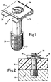
- a method of fixing a plastics article to a metal article in sealed relationship comprises providing the metal article with a plurality of projecting grooved pins (as hereinafter defined), threading the pins through pre-formed bores in the plastics article, and engaging a separate and corresponding spring clip with each pin, each clip being arranged to be in compression between the pin and the plastics article and urging the same into said relationship.
- Another aspect of the invention provides an assembly for fitting a plastics article to a metal article comprising a grooved pin having a groove near one end and means for attaching the pin to a metal article in use at the other end, and a spring clip locatable in the groove in use so as to fix the relationship of the plastics article and metal article.
- a grooved pin for the purposes of the invention can have a single parallel sided groove near its free end so as to provide an axial abutment for an engaging clip.
- a headed pin will serve in the same way, and is intended to be included in the scope of the term "grooved pin" for the purposes of this specification.
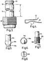
- the clip may be of sheet metal, bent into a substantially U shape; the two limbs are pierced in alignment, one with a larger hole and the second limb with a key-hole.
- the first limb is located against the article when the invention is employed, and threaded by the free end of the pin in a short axial movement of the clip.
- the second limb is then likewise engaged/threaded passing the end of the pin through the larger part of the keyhole.
- a lateral movement when the keyhole is registered with the groove, engages the clip axially, by taking the narrow part of the keyhole into the groove, due to the dimensions of that narrow part relating to the dimension of the pin at the base of the groove.
- the clip is thus fixed axially, and the springy abutment of the first limb against the face of the plastics article holds it in position with the requisite pressure.
- inlet pipes may follow any desired path to ports located at the cylinder head/manifold interface, and clips may be accessed between such pipes and the head at any position.
- each pin is made so as to be anchored in blind bores in the metal component, e.g. cylinder head.
- each pin may terminate, at the end opposite to the groove, in a helically toothed portion, apt to be pressed into such a blind bore and to broach complementary teeth in the metal surrounding the bore.
- the teeth on the pin end may be formed by a knurling operation, and subsequently hardened.
- the pin end portion which carries the teeth may be of enlarged diameter.
- the metal component may be formed with appropriate bores to receive the pins for example by a casting operation or machining, but screw-tapping is avoided.
- the pin can also have a lobed end having two or more radially protruding lobes, each separated by a groove, which lobes are physically displaced circumferentially on insertion into the hole in the metal article thereby to provide a good mechanical fit in the hole. Preferably three lobes are provided. Additionally however, the pin can comprise a self tapping end such as for example a threaded region having a transverse slot therethrough which exposes parts of the threading thereby to provide a cutting face for tapping into a hole in a metal block.
- crank case to the underside of the cylinder block, using pins threaded through the crank case after being fixed to the cylinder block.
- an assembly 10 comprising a pin 12 and clip 14 operably used to fasten a plastics article 16 to a metal article 18.
- Clip 14 can be formed from resilient material such as a bent piece of sheet metal substantially to form a U-shape comprising a first or lower limb 20 and a second or upper limb 22.
- First limb 20 comprises a receiving slot or keyhole 24 and second limb 22 comprises an aperture 26.
- Pin 12 comprises a threaded end 28 for locating in metal article 18, and a groove 30 adjacent its free end 32.
- Pin 12 has a length L between threaded end 28 and groove 30 equal to the thickness of plastics article 16.
- End 28 can comprise a pilot or guide portion 29 of smaller diameter to assist with locating pin 12 in a hole during assembly.
- pin 12 is located in metal article 18 and plastics article 16, having a preformed aperture, is located on pin 12.
- Clip 14 is positioned in groove 30 by passing the keyhole 24 of first limb 20 about the groove followed by a lowering second limb 22 and moving clip 14 laterally so that the groove 30 is engaged by part of limb 22 which defines aperture 26.
- the resilient nature of clip 14 thereby effects an axial retaining force on article 16, pressing it against article 18.
- FIG. 5 and 6 there is shown a second embodiment of a pin 12a according to the invention wherein only the lower end 28a is shown (top upper end being similar to pin 12).
- end 28a for attachment to substrate 18 such as an engine block comprises lobes 34a separated by grooves 36a.
- end 28a comprises a pilot portion 29a for guiding the pin 12a into a hole in an article 18.
- the diameter of the lobes 34a is slightly greater than the diameter of the hole into which end 28a is intended to be received in use. Accordingly, on insertion of pin 12a into a hole, lobes 34a spread circumferentially into grooves 36a and provide a tight frictional fit within the hole.
- pin 12b comprises an end 28b comprising threading 38b and a slot 40b.
- the slot 40b exposes the threading 38b at the edges of the slot and these exposed regions of the threading effect self tapping by threaded end 28b on rotational insertion of pin 12b into a hole.
Abstract
Description
Claims (13)
- A method of fixing a plastics article to a metal article in sealed relationship comprises providing the metal article with a plurality of projecting grooved pins, threading the pins through pre-formed bores in the plastics article, and engaging a separate and corresponding spring clip with each pin, each clip being arranged to be in compression between the pin and the plastics article and urging the same into said relationship.
- A method according to Claim 1 wherein the spring clip comprises two portions resiliently biased away from one another and wherein the method of fixing a plastics article further comprises of the steps of locating the first portion against the plastics article and engaging the second portion of the clip in the groove of the pin.
- A method according to Claim 2 wherein the spring clip comprises a substantially U shaped member, the limbs of which form the first and second portions and wherein the first portion comprises a slot and the second portion comprises an aperture such that location of the spring clip into engagement with the pin and plastics article can be achieved by sliding the end of the pin into the slot of the first portion followed by passing the second portion over the pin so that the pin protrudes over the aperture and then laterally moving the clip so that the second portion engages the groove of the pin.
- An assembly for fitting a plastics article to a metal article comprising a grooved pin having a groove near one end and means for attaching the pin to a metal article in use at the other end, and a spring clip locatable in the groove in use so as to fix the relationship of the plastics article and metal article.
- An assembly according to Claim 4 wherein the pin comprises a parallel sided groove near one end, and preferably only a single groove.
- An assembly according to Claims 4 or 5 wherein the clip comprises substantially a U shape.
- An assembly according to Claim 6 wherein the U shaped clip comprises first and second portions forming the two limbs of the clip and wherein a first portion comprises a slot and the second portion comprises an aperture at least partially aligned with the slot so as to enable the pin to pass through both the slot and aperture.
- An assembly according to any of Claims 4 to 7 wherein the pin comprises a grooved end for attachment to the metal block through frictional co-operation between the grooved end and sides of the hole in the metal block into which the pin is located in use.
- An assembly according to any of Claims 4 to 8 wherein the pin comprises a lobed end having two or more lobes separated from one another by a groove enabling displacement of part of the lobe into the groove due to mechanical attachment of the lobed end of the pin into a hole in a metal block in use.
- An assembly according to any of Claims 4 to 8 wherein the pin comprises a threaded end enabling self tapping by the pin on insertion into a hole in a metal object.
- An assembly according to Claim 10 wherein the threaded end comprises a transverse slot which exposes edges of the threading of the end to provide a cutting face.
- An assembly according to any of Claims 4 to 11 wherein the pin comprises a pilot portion at the end opposite to the grooved end thereby to enable location of the pin in a hole in a metal object in use.
- An engine block for an internal combustion engine comprising a metal block and plastics manifold such as an air intake manifold, attached to the metal block by an assembly according to any of Claims 4-12.
Applications Claiming Priority (2)
| Application Number | Priority Date | Filing Date | Title |
|---|---|---|---|
| GB9802058 | 1998-01-31 | ||
| GB9802058A GB9802058D0 (en) | 1998-01-31 | 1998-01-31 | Fixing articles together |
Publications (2)
| Publication Number | Publication Date |
|---|---|
| EP0933537A2 true EP0933537A2 (en) | 1999-08-04 |
| EP0933537A3 EP0933537A3 (en) | 2000-07-19 |
Family
ID=10826203
Family Applications (1)
| Application Number | Title | Priority Date | Filing Date |
|---|---|---|---|
| EP99300537A Withdrawn EP0933537A3 (en) | 1998-01-31 | 1999-01-26 | Fixing articles together |
Country Status (3)
| Country | Link |
|---|---|
| EP (1) | EP0933537A3 (en) |
| JP (1) | JPH11270528A (en) |
| GB (2) | GB9802058D0 (en) |
Cited By (4)
| Publication number | Priority date | Publication date | Assignee | Title |
|---|---|---|---|---|
| FR2921987A1 (en) * | 2007-10-09 | 2009-04-10 | Renault Sas | FIXING ASSEMBLY |
| WO2013036910A2 (en) * | 2011-09-08 | 2013-03-14 | Visor Frames, LLC | Rotating attachment device and method of use |
| CN106678151A (en) * | 2016-12-26 | 2017-05-17 | 北汽福田汽车股份有限公司 | Pin shaft locating component, pin shaft locating assembly, front suspension assembly and vehicle |
| EP3998132A4 (en) * | 2019-07-12 | 2022-10-05 | Koki Holdings Co., Ltd. | Power tool |
Families Citing this family (2)
| Publication number | Priority date | Publication date | Assignee | Title |
|---|---|---|---|---|
| DE10052039C2 (en) * | 2000-10-20 | 2002-10-31 | Ebm Werke Gmbh & Co Kg | Axial shaft lock and locking element |
| JP6007357B2 (en) * | 2013-11-18 | 2016-10-12 | 日信工業株式会社 | Electronic control device and vehicle brake fluid pressure control device |
Family Cites Families (7)
| Publication number | Priority date | Publication date | Assignee | Title |
|---|---|---|---|---|
| US2093171A (en) * | 1933-01-27 | 1937-09-14 | Illinois Tool Works | Tapping screw |
| US3178987A (en) * | 1962-10-16 | 1965-04-20 | Gen Motors Corp | Retainer clip |
| DE3302752C2 (en) * | 1983-01-27 | 1986-09-25 | Daimler-Benz Ag, 7000 Stuttgart | Axial thrust safety clamp for a bolt penetrating a component |
| DE3332082A1 (en) * | 1983-09-06 | 1985-03-21 | Volkswagenwerk Ag, 3180 Wolfsburg | Securing bracket for a sleeve which is supported on a bolt |
| DE3733975C1 (en) * | 1987-10-08 | 1989-01-26 | Opel Adam Ag | Bolt-securing means |
| DE4305330A1 (en) * | 1993-02-20 | 1994-08-25 | Fischer Artur Werke Gmbh | Fastening element which is designed as a nail and has an expansion region |
| DE19528047A1 (en) * | 1995-07-31 | 1997-02-06 | Bosch Gmbh Robert | Internal combustion engine with an attached suction module or intake manifold and method for attaching an intake module or intake manifold to an internal combustion engine |
-
1998
- 1998-01-31 GB GB9802058A patent/GB9802058D0/en not_active Ceased
-
1999
- 1999-01-25 GB GB9901405A patent/GB2334747B/en not_active Expired - Fee Related
- 1999-01-26 EP EP99300537A patent/EP0933537A3/en not_active Withdrawn
- 1999-01-28 JP JP2044299A patent/JPH11270528A/en active Pending
Non-Patent Citations (1)
| Title |
|---|
| None |
Cited By (7)
| Publication number | Priority date | Publication date | Assignee | Title |
|---|---|---|---|---|
| FR2921987A1 (en) * | 2007-10-09 | 2009-04-10 | Renault Sas | FIXING ASSEMBLY |
| EP2048376A1 (en) | 2007-10-09 | 2009-04-15 | Renault s.a.s. | Securing assembly |
| WO2013036910A2 (en) * | 2011-09-08 | 2013-03-14 | Visor Frames, LLC | Rotating attachment device and method of use |
| WO2013036910A3 (en) * | 2011-09-08 | 2013-05-02 | Visor Frames, LLC | Rotating attachment device and method of use |
| US9388834B2 (en) | 2011-09-08 | 2016-07-12 | Visor Frames, LLC | Rotating attachment device and method of use |
| CN106678151A (en) * | 2016-12-26 | 2017-05-17 | 北汽福田汽车股份有限公司 | Pin shaft locating component, pin shaft locating assembly, front suspension assembly and vehicle |
| EP3998132A4 (en) * | 2019-07-12 | 2022-10-05 | Koki Holdings Co., Ltd. | Power tool |
Also Published As
| Publication number | Publication date |
|---|---|
| GB2334747B (en) | 2000-02-23 |
| GB2334747A (en) | 1999-09-01 |
| GB9901405D0 (en) | 1999-03-10 |
| JPH11270528A (en) | 1999-10-05 |
| EP0933537A3 (en) | 2000-07-19 |
| GB9802058D0 (en) | 1998-03-25 |
Similar Documents
| Publication | Publication Date | Title |
|---|---|---|
| EP0892183B1 (en) | Fastener assembly with sleeve | |
| US7334572B1 (en) | System and method for securing fuel injectors | |
| US20020139334A1 (en) | Valve timing regulation device | |
| US7311087B2 (en) | Fuel pump with a guided tappet assembly and methods for guiding and assembly | |
| US8403783B2 (en) | Hydraulic tensioner with a band type check valve | |
| EP0933537A2 (en) | Fixing articles together | |
| JP2877117B2 (en) | Direct injection multi-cylinder engine | |
| EP1441149B1 (en) | Cam chain tensioner | |
| US20160222835A1 (en) | Valve timing control device for internal combustion engine, and fastening structure | |
| US20100223771A1 (en) | Concentric camshaft and method of assembly | |
| JPH1082355A (en) | Fuel injection nozzle fixing device on direct injection type diesel engine | |
| US20040211385A1 (en) | Camshaft mounting structure for a cylinder head | |
| US7975381B2 (en) | Valve operating camshaft system for internal combustion engine | |
| EP2495406A1 (en) | Device for controlling timing of valve opening/closing | |
| US8109246B2 (en) | Camshaft damping mechanism and method of assembly | |
| US6354972B1 (en) | Chain tensioner assembly having a single-fastener mounting arrangement | |
| KR0180264B1 (en) | Cylinder head gasket with areas of relatively high rigidity | |
| US5642701A (en) | Engine cylinder head assembly having planar and cast components | |
| US20060255547A1 (en) | Zip strip seal | |
| US5327814A (en) | Mechanical assemblies and methods of making same | |
| US5361740A (en) | Mechanical assemblies with hardened bearing surfaces | |
| EP1522682A1 (en) | A camshaft drive assembly and a case and a chain guide for a camshaft drive assembly | |
| JP4164553B2 (en) | Molding method of delivery pipe mounting bracket member | |
| US6684859B2 (en) | Fuel injector tappet retention mechanism | |
| JP3635192B2 (en) | Chain tensioner |
Legal Events
| Date | Code | Title | Description |
|---|---|---|---|
| PUAI | Public reference made under article 153(3) epc to a published international application that has entered the european phase |
Free format text: ORIGINAL CODE: 0009012 |
|
| AK | Designated contracting states |
Kind code of ref document: A2 Designated state(s): DE FR IT |
|
| AX | Request for extension of the european patent |
Free format text: AL;LT;LV;MK;RO;SI |
|
| PUAL | Search report despatched |
Free format text: ORIGINAL CODE: 0009013 |
|
| AK | Designated contracting states |
Kind code of ref document: A3 Designated state(s): AT BE CH CY DE DK ES FI FR GB GR IE IT LI LU MC NL PT SE |
|
| AX | Request for extension of the european patent |
Free format text: AL;LT;LV;MK;RO;SI |
|
| RAP1 | Party data changed (applicant data changed or rights of an application transferred) |
Owner name: MCKECHNIE SPECIALIST PRODUCTS LIMITED |
|
| 17P | Request for examination filed |
Effective date: 20010115 |
|
| AKX | Designation fees paid |
Free format text: DE FR IT |
|
| 17Q | First examination report despatched |
Effective date: 20020924 |
|
| STAA | Information on the status of an ep patent application or granted ep patent |
Free format text: STATUS: THE APPLICATION IS DEEMED TO BE WITHDRAWN |
|
| 18D | Application deemed to be withdrawn |
Effective date: 20030205 |