EP3174178A1 - Drahtloses leistungsübertragungssystem - Google Patents
Drahtloses leistungsübertragungssystem Download PDFInfo
- Publication number
- EP3174178A1 EP3174178A1 EP16203739.4A EP16203739A EP3174178A1 EP 3174178 A1 EP3174178 A1 EP 3174178A1 EP 16203739 A EP16203739 A EP 16203739A EP 3174178 A1 EP3174178 A1 EP 3174178A1
- Authority
- EP
- European Patent Office
- Prior art keywords
- power transmitting
- power
- wireless power
- power receiving
- antenna
- Prior art date
- Legal status (The legal status is an assumption and is not a legal conclusion. Google has not performed a legal analysis and makes no representation as to the accuracy of the status listed.)
- Withdrawn
Links
Images


Classifications
-
- B—PERFORMING OPERATIONS; TRANSPORTING
- B60—VEHICLES IN GENERAL
- B60L—PROPULSION OF ELECTRICALLY-PROPELLED VEHICLES; SUPPLYING ELECTRIC POWER FOR AUXILIARY EQUIPMENT OF ELECTRICALLY-PROPELLED VEHICLES; ELECTRODYNAMIC BRAKE SYSTEMS FOR VEHICLES IN GENERAL; MAGNETIC SUSPENSION OR LEVITATION FOR VEHICLES; MONITORING OPERATING VARIABLES OF ELECTRICALLY-PROPELLED VEHICLES; ELECTRIC SAFETY DEVICES FOR ELECTRICALLY-PROPELLED VEHICLES
- B60L53/00—Methods of charging batteries, specially adapted for electric vehicles; Charging stations or on-board charging equipment therefor; Exchange of energy storage elements in electric vehicles
- B60L53/10—Methods of charging batteries, specially adapted for electric vehicles; Charging stations or on-board charging equipment therefor; Exchange of energy storage elements in electric vehicles characterised by the energy transfer between the charging station and the vehicle
- B60L53/12—Inductive energy transfer
- B60L53/124—Detection or removal of foreign bodies
-
- B—PERFORMING OPERATIONS; TRANSPORTING
- B60—VEHICLES IN GENERAL
- B60L—PROPULSION OF ELECTRICALLY-PROPELLED VEHICLES; SUPPLYING ELECTRIC POWER FOR AUXILIARY EQUIPMENT OF ELECTRICALLY-PROPELLED VEHICLES; ELECTRODYNAMIC BRAKE SYSTEMS FOR VEHICLES IN GENERAL; MAGNETIC SUSPENSION OR LEVITATION FOR VEHICLES; MONITORING OPERATING VARIABLES OF ELECTRICALLY-PROPELLED VEHICLES; ELECTRIC SAFETY DEVICES FOR ELECTRICALLY-PROPELLED VEHICLES
- B60L50/00—Electric propulsion with power supplied within the vehicle
- B60L50/20—Electric propulsion with power supplied within the vehicle using propulsion power generated by humans or animals
-
- B—PERFORMING OPERATIONS; TRANSPORTING
- B60—VEHICLES IN GENERAL
- B60L—PROPULSION OF ELECTRICALLY-PROPELLED VEHICLES; SUPPLYING ELECTRIC POWER FOR AUXILIARY EQUIPMENT OF ELECTRICALLY-PROPELLED VEHICLES; ELECTRODYNAMIC BRAKE SYSTEMS FOR VEHICLES IN GENERAL; MAGNETIC SUSPENSION OR LEVITATION FOR VEHICLES; MONITORING OPERATING VARIABLES OF ELECTRICALLY-PROPELLED VEHICLES; ELECTRIC SAFETY DEVICES FOR ELECTRICALLY-PROPELLED VEHICLES
- B60L53/00—Methods of charging batteries, specially adapted for electric vehicles; Charging stations or on-board charging equipment therefor; Exchange of energy storage elements in electric vehicles
- B60L53/30—Constructional details of charging stations
- B60L53/35—Means for automatic or assisted adjustment of the relative position of charging devices and vehicles
- B60L53/36—Means for automatic or assisted adjustment of the relative position of charging devices and vehicles by positioning the vehicle
-
- B—PERFORMING OPERATIONS; TRANSPORTING
- B60—VEHICLES IN GENERAL
- B60L—PROPULSION OF ELECTRICALLY-PROPELLED VEHICLES; SUPPLYING ELECTRIC POWER FOR AUXILIARY EQUIPMENT OF ELECTRICALLY-PROPELLED VEHICLES; ELECTRODYNAMIC BRAKE SYSTEMS FOR VEHICLES IN GENERAL; MAGNETIC SUSPENSION OR LEVITATION FOR VEHICLES; MONITORING OPERATING VARIABLES OF ELECTRICALLY-PROPELLED VEHICLES; ELECTRIC SAFETY DEVICES FOR ELECTRICALLY-PROPELLED VEHICLES
- B60L53/00—Methods of charging batteries, specially adapted for electric vehicles; Charging stations or on-board charging equipment therefor; Exchange of energy storage elements in electric vehicles
- B60L53/50—Charging stations characterised by energy-storage or power-generation means
- B60L53/51—Photovoltaic means
-
- H—ELECTRICITY
- H01—ELECTRIC ELEMENTS
- H01F—MAGNETS; INDUCTANCES; TRANSFORMERS; SELECTION OF MATERIALS FOR THEIR MAGNETIC PROPERTIES
- H01F38/00—Adaptations of transformers or inductances for specific applications or functions
- H01F38/14—Inductive couplings
-
- H—ELECTRICITY
- H02—GENERATION; CONVERSION OR DISTRIBUTION OF ELECTRIC POWER
- H02J—CIRCUIT ARRANGEMENTS OR SYSTEMS FOR SUPPLYING OR DISTRIBUTING ELECTRIC POWER; SYSTEMS FOR STORING ELECTRIC ENERGY
- H02J50/00—Circuit arrangements or systems for wireless supply or distribution of electric power
- H02J50/10—Circuit arrangements or systems for wireless supply or distribution of electric power using inductive coupling
- H02J50/12—Circuit arrangements or systems for wireless supply or distribution of electric power using inductive coupling of the resonant type
-
- H—ELECTRICITY
- H02—GENERATION; CONVERSION OR DISTRIBUTION OF ELECTRIC POWER
- H02J—CIRCUIT ARRANGEMENTS OR SYSTEMS FOR SUPPLYING OR DISTRIBUTING ELECTRIC POWER; SYSTEMS FOR STORING ELECTRIC ENERGY
- H02J50/00—Circuit arrangements or systems for wireless supply or distribution of electric power
- H02J50/20—Circuit arrangements or systems for wireless supply or distribution of electric power using microwaves or radio frequency waves
-
- H—ELECTRICITY
- H02—GENERATION; CONVERSION OR DISTRIBUTION OF ELECTRIC POWER
- H02J—CIRCUIT ARRANGEMENTS OR SYSTEMS FOR SUPPLYING OR DISTRIBUTING ELECTRIC POWER; SYSTEMS FOR STORING ELECTRIC ENERGY
- H02J50/00—Circuit arrangements or systems for wireless supply or distribution of electric power
- H02J50/60—Circuit arrangements or systems for wireless supply or distribution of electric power responsive to the presence of foreign objects, e.g. detection of living beings
-
- H—ELECTRICITY
- H02—GENERATION; CONVERSION OR DISTRIBUTION OF ELECTRIC POWER
- H02J—CIRCUIT ARRANGEMENTS OR SYSTEMS FOR SUPPLYING OR DISTRIBUTING ELECTRIC POWER; SYSTEMS FOR STORING ELECTRIC ENERGY
- H02J50/00—Circuit arrangements or systems for wireless supply or distribution of electric power
- H02J50/80—Circuit arrangements or systems for wireless supply or distribution of electric power involving the exchange of data, concerning supply or distribution of electric power, between transmitting devices and receiving devices
-
- H—ELECTRICITY
- H02—GENERATION; CONVERSION OR DISTRIBUTION OF ELECTRIC POWER
- H02J—CIRCUIT ARRANGEMENTS OR SYSTEMS FOR SUPPLYING OR DISTRIBUTING ELECTRIC POWER; SYSTEMS FOR STORING ELECTRIC ENERGY
- H02J50/00—Circuit arrangements or systems for wireless supply or distribution of electric power
- H02J50/90—Circuit arrangements or systems for wireless supply or distribution of electric power involving detection or optimisation of position, e.g. alignment
-
- B—PERFORMING OPERATIONS; TRANSPORTING
- B60—VEHICLES IN GENERAL
- B60L—PROPULSION OF ELECTRICALLY-PROPELLED VEHICLES; SUPPLYING ELECTRIC POWER FOR AUXILIARY EQUIPMENT OF ELECTRICALLY-PROPELLED VEHICLES; ELECTRODYNAMIC BRAKE SYSTEMS FOR VEHICLES IN GENERAL; MAGNETIC SUSPENSION OR LEVITATION FOR VEHICLES; MONITORING OPERATING VARIABLES OF ELECTRICALLY-PROPELLED VEHICLES; ELECTRIC SAFETY DEVICES FOR ELECTRICALLY-PROPELLED VEHICLES
- B60L2200/00—Type of vehicles
- B60L2200/12—Bikes
-
- B—PERFORMING OPERATIONS; TRANSPORTING
- B60—VEHICLES IN GENERAL
- B60L—PROPULSION OF ELECTRICALLY-PROPELLED VEHICLES; SUPPLYING ELECTRIC POWER FOR AUXILIARY EQUIPMENT OF ELECTRICALLY-PROPELLED VEHICLES; ELECTRODYNAMIC BRAKE SYSTEMS FOR VEHICLES IN GENERAL; MAGNETIC SUSPENSION OR LEVITATION FOR VEHICLES; MONITORING OPERATING VARIABLES OF ELECTRICALLY-PROPELLED VEHICLES; ELECTRIC SAFETY DEVICES FOR ELECTRICALLY-PROPELLED VEHICLES
- B60L2210/00—Converter types
- B60L2210/10—DC to DC converters
-
- B—PERFORMING OPERATIONS; TRANSPORTING
- B60—VEHICLES IN GENERAL
- B60L—PROPULSION OF ELECTRICALLY-PROPELLED VEHICLES; SUPPLYING ELECTRIC POWER FOR AUXILIARY EQUIPMENT OF ELECTRICALLY-PROPELLED VEHICLES; ELECTRODYNAMIC BRAKE SYSTEMS FOR VEHICLES IN GENERAL; MAGNETIC SUSPENSION OR LEVITATION FOR VEHICLES; MONITORING OPERATING VARIABLES OF ELECTRICALLY-PROPELLED VEHICLES; ELECTRIC SAFETY DEVICES FOR ELECTRICALLY-PROPELLED VEHICLES
- B60L2210/00—Converter types
- B60L2210/30—AC to DC converters
-
- B—PERFORMING OPERATIONS; TRANSPORTING
- B60—VEHICLES IN GENERAL
- B60L—PROPULSION OF ELECTRICALLY-PROPELLED VEHICLES; SUPPLYING ELECTRIC POWER FOR AUXILIARY EQUIPMENT OF ELECTRICALLY-PROPELLED VEHICLES; ELECTRODYNAMIC BRAKE SYSTEMS FOR VEHICLES IN GENERAL; MAGNETIC SUSPENSION OR LEVITATION FOR VEHICLES; MONITORING OPERATING VARIABLES OF ELECTRICALLY-PROPELLED VEHICLES; ELECTRIC SAFETY DEVICES FOR ELECTRICALLY-PROPELLED VEHICLES
- B60L2210/00—Converter types
- B60L2210/40—DC to AC converters
-
- B—PERFORMING OPERATIONS; TRANSPORTING
- B60—VEHICLES IN GENERAL
- B60L—PROPULSION OF ELECTRICALLY-PROPELLED VEHICLES; SUPPLYING ELECTRIC POWER FOR AUXILIARY EQUIPMENT OF ELECTRICALLY-PROPELLED VEHICLES; ELECTRODYNAMIC BRAKE SYSTEMS FOR VEHICLES IN GENERAL; MAGNETIC SUSPENSION OR LEVITATION FOR VEHICLES; MONITORING OPERATING VARIABLES OF ELECTRICALLY-PROPELLED VEHICLES; ELECTRIC SAFETY DEVICES FOR ELECTRICALLY-PROPELLED VEHICLES
- B60L2240/00—Control parameters of input or output; Target parameters
- B60L2240/10—Vehicle control parameters
- B60L2240/36—Temperature of vehicle components or parts
-
- H—ELECTRICITY
- H02—GENERATION; CONVERSION OR DISTRIBUTION OF ELECTRIC POWER
- H02J—CIRCUIT ARRANGEMENTS OR SYSTEMS FOR SUPPLYING OR DISTRIBUTING ELECTRIC POWER; SYSTEMS FOR STORING ELECTRIC ENERGY
- H02J7/00—Circuit arrangements for charging or depolarising batteries or for supplying loads from batteries
- H02J7/34—Parallel operation in networks using both storage and other dc sources, e.g. providing buffering
- H02J7/35—Parallel operation in networks using both storage and other dc sources, e.g. providing buffering with light sensitive cells
-
- Y—GENERAL TAGGING OF NEW TECHNOLOGICAL DEVELOPMENTS; GENERAL TAGGING OF CROSS-SECTIONAL TECHNOLOGIES SPANNING OVER SEVERAL SECTIONS OF THE IPC; TECHNICAL SUBJECTS COVERED BY FORMER USPC CROSS-REFERENCE ART COLLECTIONS [XRACs] AND DIGESTS
- Y02—TECHNOLOGIES OR APPLICATIONS FOR MITIGATION OR ADAPTATION AGAINST CLIMATE CHANGE
- Y02T—CLIMATE CHANGE MITIGATION TECHNOLOGIES RELATED TO TRANSPORTATION
- Y02T10/00—Road transport of goods or passengers
- Y02T10/60—Other road transportation technologies with climate change mitigation effect
- Y02T10/70—Energy storage systems for electromobility, e.g. batteries
-
- Y—GENERAL TAGGING OF NEW TECHNOLOGICAL DEVELOPMENTS; GENERAL TAGGING OF CROSS-SECTIONAL TECHNOLOGIES SPANNING OVER SEVERAL SECTIONS OF THE IPC; TECHNICAL SUBJECTS COVERED BY FORMER USPC CROSS-REFERENCE ART COLLECTIONS [XRACs] AND DIGESTS
- Y02—TECHNOLOGIES OR APPLICATIONS FOR MITIGATION OR ADAPTATION AGAINST CLIMATE CHANGE
- Y02T—CLIMATE CHANGE MITIGATION TECHNOLOGIES RELATED TO TRANSPORTATION
- Y02T10/00—Road transport of goods or passengers
- Y02T10/60—Other road transportation technologies with climate change mitigation effect
- Y02T10/7072—Electromobility specific charging systems or methods for batteries, ultracapacitors, supercapacitors or double-layer capacitors
-
- Y—GENERAL TAGGING OF NEW TECHNOLOGICAL DEVELOPMENTS; GENERAL TAGGING OF CROSS-SECTIONAL TECHNOLOGIES SPANNING OVER SEVERAL SECTIONS OF THE IPC; TECHNICAL SUBJECTS COVERED BY FORMER USPC CROSS-REFERENCE ART COLLECTIONS [XRACs] AND DIGESTS
- Y02—TECHNOLOGIES OR APPLICATIONS FOR MITIGATION OR ADAPTATION AGAINST CLIMATE CHANGE
- Y02T—CLIMATE CHANGE MITIGATION TECHNOLOGIES RELATED TO TRANSPORTATION
- Y02T10/00—Road transport of goods or passengers
- Y02T10/60—Other road transportation technologies with climate change mitigation effect
- Y02T10/72—Electric energy management in electromobility
-
- Y—GENERAL TAGGING OF NEW TECHNOLOGICAL DEVELOPMENTS; GENERAL TAGGING OF CROSS-SECTIONAL TECHNOLOGIES SPANNING OVER SEVERAL SECTIONS OF THE IPC; TECHNICAL SUBJECTS COVERED BY FORMER USPC CROSS-REFERENCE ART COLLECTIONS [XRACs] AND DIGESTS
- Y02—TECHNOLOGIES OR APPLICATIONS FOR MITIGATION OR ADAPTATION AGAINST CLIMATE CHANGE
- Y02T—CLIMATE CHANGE MITIGATION TECHNOLOGIES RELATED TO TRANSPORTATION
- Y02T90/00—Enabling technologies or technologies with a potential or indirect contribution to GHG emissions mitigation
- Y02T90/10—Technologies relating to charging of electric vehicles
- Y02T90/12—Electric charging stations
-
- Y—GENERAL TAGGING OF NEW TECHNOLOGICAL DEVELOPMENTS; GENERAL TAGGING OF CROSS-SECTIONAL TECHNOLOGIES SPANNING OVER SEVERAL SECTIONS OF THE IPC; TECHNICAL SUBJECTS COVERED BY FORMER USPC CROSS-REFERENCE ART COLLECTIONS [XRACs] AND DIGESTS
- Y02—TECHNOLOGIES OR APPLICATIONS FOR MITIGATION OR ADAPTATION AGAINST CLIMATE CHANGE
- Y02T—CLIMATE CHANGE MITIGATION TECHNOLOGIES RELATED TO TRANSPORTATION
- Y02T90/00—Enabling technologies or technologies with a potential or indirect contribution to GHG emissions mitigation
- Y02T90/10—Technologies relating to charging of electric vehicles
- Y02T90/14—Plug-in electric vehicles
Definitions
- the present disclosure relates to a wireless power transmission system for wirelessly and contactlessly transmitting power using resonant magnetic coupling.
- the present disclosure also relates to a wireless power transmitting apparatus and a wireless power receiving apparatus which are used in the wireless power transmission system, and relates to control circuits of the wireless power transmitting apparatus and the wireless power receiving apparatus.
- Patent Document 1 discloses a wireless power transmission apparatus for transmitting energy through space between two resonant circuits.
- the wireless power transmission apparatus wirelessly (contactlessly) transmits oscillating energy by coupling two resonant circuits through leakage of oscillating energy at a resonance frequency (evanescent tail) generated in space around the resonant circuits.
- a metal foreign object is present near a coil of a power transmitting resonant circuit or a coil of a power receiving resonant circuit during power transmission of a wireless power transmission system, an eddy current may be generated on the metal foreign object, resulting in heating of the metal foreign object. In order to safely use the wireless power transmission system, it is necessary to suppress heating of the metal foreign object.
- the noncontact power transmission systems disclosed in the Patent Document 2 stop power transmission upon detecting a metal foreign object, thus suppressing heating of the metal foreign object.
- the wireless power transmission system cannot resume power transmission unless a user removes the metal foreign object.
- the object of the present disclosure is to solve the above problems, and to provide a wireless power transmission system in which, even if a metal foreign object is present near a coil of a power transmitting resonant circuit or a coil of a power receiving resonant circuit, it is possible to continue power transmission without immediately stopping the power transmission, while suppressing heating of the metal foreign object.
- the object of the present disclosure is to a wireless power transmitting apparatus and a wireless power receiving apparatus which are used in the wireless power transmission system, and relates to control circuits of the wireless power transmitting apparatus and the wireless power receiving apparatus.
- a control circuit of a wireless power transmitting apparatus in a wireless power transmission system for transmitting high-frequency power from the wireless power transmitting apparatus having a power transmitting antenna to a power receiving antenna.
- the power transmitting antenna includes a first resonant circuit including a power transmitting coil
- the power receiving antenna includes a second resonant circuit including a power receiving coil.
- the power transmitting antenna and the power receiving antenna When the power transmitting antenna and the power receiving antenna are electromagnetically coupled to each other, the power transmitting antenna and the power receiving antenna have an odd-mode resonance frequency corresponding to an odd-mode resonant condition, and an even-mode resonance frequency corresponding to an even-mode resonant condition, and the even-mode resonance frequency is higher than the odd-mode resonance frequency.
- the wireless power transmitting apparatus is further provided with a power transmitting circuit configured to generate, from input power, high-frequency power at a variable frequency, and supply the high-frequency power to the power transmitting antenna, under control of the control circuit of the wireless power transmitting apparatus.
- the control circuit of the wireless power transmitting apparatus sets the frequency of the high-frequency power generated by the power transmitting circuit to one of the odd-mode resonance frequency and the even-mode resonance frequency.
- control circuit of the wireless power transmitting apparatus of the present disclosure even when a metal foreign object is present near the power transmitting coil or the power receiving coil, it is possible to continue power transmission without immediately stopping the power transmission, while suppressing heating of the metal foreign object.
- Fig. 1 is a block diagram showing a configuration of a wireless power transmission system 10 according to a first embodiment.
- the wireless power transmission system 10 includes: a wireless power transmitting apparatus 2 connected to a power supply apparatus 1; and a power receiving antenna 31 connected to a load apparatus 4.
- the wireless power transmission system 10 wirelessly transmits high-frequency power from a power transmitting antenna 22 of the wireless power transmitting apparatus 2 to the power receiving antenna.
- the power supply apparatus 1 converts alternating-current power from a commercial alternating-current power supply, into direct-current power, and outputs the direct-current power to the wireless power transmission system 10.
- the power supply apparatus 1 converts the voltage of direct-current power from a direct-current power supply such as a battery, and outputs the power to the wireless power transmitting apparatus 2.
- the wireless power transmission system 10 converts the direct-current power from the power supply apparatus 1 into high-frequency power and wirelessly transmits the high-frequency power, and then, outputs the high-frequency power to the load apparatus 4. From now on, the configuration and operation of the wireless power transmission system 10 will be described with reference to an exemplary case where the load apparatus 4 is a battery charger for a mobile phone.
- the wireless power transmitting apparatus 2 is provided with an oscillator circuit 21, the power transmitting antenna 22, and a control circuit 23.
- the oscillator circuit 21 operates as a power transmitting circuit for generating, from inputted direct-current power, high-frequency power at a variable frequency, and supply the high-frequency power to the power transmitting antenna 22, under the control of the control circuit 23.
- the oscillator circuit 21 is provided with: a pulse generator for generating a pulse sequence with a variable transmission frequency ftr; and a class-D amplifier including a switching element operable according to the pulse sequence.
- the oscillator circuit 21 generates high-frequency power with the transmission frequency ftr.
- the power transmitting antenna 22 includes an LC resonant circuit, and the power receiving antenna 31 also includes an LC resonant circuit.
- the power receiving antenna 31 is electromagnetically coupled to the power transmitting antenna 22.
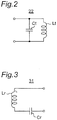
- Fig. 2 is a circuit diagram showing a configuration of a power transmitting antenna 22 of Fig. 1 .
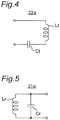
- Fig. 3 is a circuit diagram showing a configuration of a power receiving antenna 31 of Fig. 1 .
- the power transmitting antenna 22 is configured to include an LC parallel resonant circuit including a resonant capacitor Ct and a power transmitting coil Lt connected in parallel, and the LC parallel resonant circuit having a resonance frequency fT.
- Fig. 2 is a circuit diagram showing a configuration of a power transmitting antenna 22 of Fig. 1 .
- the power transmitting antenna 22 is configured to include an LC parallel resonant circuit including a resonant capacitor Ct and a power transmitting coil Lt connected in parallel, and the LC parallel resonant circuit having a resonance frequency fT.
- the power receiving antenna 31 is configured to include an LC series resonant circuit including a resonant capacitor Cr and a power receiving coil Lr connected in series, and the LC series resonant circuit having a resonance frequency fR.
- Fig. 6 is a perspective view showing an implementation example of the power transmitting antenna 22 and the power receiving antenna 31 of Fig. 1 .
- the power transmitting coil Lt and the power receiving coil Lr are, for example, square spiral coils.
- the power transmitting coil Lt and the power receiving coil Lr have substantially planar configurations, so as to be opposed to each other with a certain gap "g" therebetween.
- Fig. 7 is a perspective view showing a configuration of a modified embodiment of the power transmitting coil Lt and the power receiving coil Lr of Fig. 6 .
- the power transmitting coil Lt and the power receiving coil Lr may be, for example, circular spiral coils.
- each of the power transmitting coil Lt and the power receiving coil Lr is, for example, a spiral coil including a winding wound substantially on a plane, and having a square or other shape.
- Each of the power transmitting coil Lt and the power receiving coil Lr has a central portion and a peripheral portion.
- the power transmitting coil 22 is provided close to the power receiving coil 31 such that, when the power transmitting antenna 22 and the power receiving antenna 31 are electromagnetically coupled to each other, the central portion of the power transmitting coil Lt is opposed to the central portion of the power receiving coil Lr, and the peripheral portion of the power transmitting coil Lt is opposed to the peripheral portion of the power receiving coil Lr.
- each winding of the power transmitting coil Lt and the power receiving coil Lr is not limited to being wound on a plane, and may be wound on a curved surface or in any other shape, as long as the central portion of the power transmitting coil Lt is opposed to the central portion of the power receiving coil Lr, and the peripheral portion of the power transmitting coil Lt is opposed to the peripheral portion of the power receiving coil Lr.
- at least a part of the windings of the power transmitting coil Lt and the power receiving coil Lr may be wound such that the central portion of the power transmitting coil Lt is opposed to the central portion of the power receiving coil Lr, and the peripheral portion of the power transmitting coil Lt is opposed to the peripheral portion of the power receiving coil Lr.
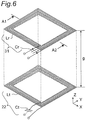
- Fig. 4 is a circuit diagram showing a configuration of a power transmitting antenna 22a according to a modified embodiment of the power transmitting antenna 22 of Fig. 2 .
- the power transmitting antenna 22a of Fig. 4 may be used instead of the power transmitting antenna 22 of Fig. 2 .
- the power transmitting antenna 22a is a series resonant circuit including a resonant capacitor Ct and a power transmitting coil Lt.
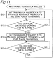
- FIG. 5 is a circuit diagram showing a configuration of a power receiving antenna 31a according to a modified embodiment of the power receiving antenna 31 of Fig. 3 .
- the power receiving antenna 31a of Fig. 5 may be used instead of the power receiving antenna 31 of Fig. 3 .
- the power receiving antenna 31a is a parallel resonant circuit including a resonant capacitor Cr and a power receiving coil Lr.
- each of the power transmitting antenna and the power receiving antenna may be a self-resonant circuit using its wire's parasitic capacitance.
- One of the power transmitting antenna 22 and the power receiving antenna 31 may include a coil and a capacitor connected in series, and the other may include a coil and a capacitor connected in parallel.
- both the power transmitting antenna 22 and the power receiving antenna 31 may include a coil and a capacitor connected in series, and both the power transmitting antenna 22 and the power receiving antenna 31 may include a coil and a capacitor connected in parallel.
- an output impedance Zt1 for the case where an input terminal of the power transmitting antenna 22 is seen from an output terminal of the oscillator circuit 21 is set to be substantially equal to an input impedance Zt2 for the case where the output terminal of the oscillator circuit 21 is seen from the input terminal of the power transmitting antenna 22.
- an output impedance Zr1 for the case where the load apparatus 4 is seen from an output terminal of the power receiving antenna 31 is set to be substantially equal to an input impedance Zr2 for the case where the output terminal of the power receiving antenna 31 is seen from the load apparatus 4.
- substantially equal in impedance means that the difference between the absolute values of the impedances is 25 % or less than the absolute value of the higher one of the impedances.
- the oscillator circuit 21 drives the switching element of the above-described class-D amplifier according to the pulse sequence with the transmission frequency ftr, and thus, converts a direct-current voltage from the power supply apparatus 1, into a high-frequency voltage, and outputs the high-frequency voltage to the power transmitting antenna 22.
- the power transmitting antenna 22 is provided close to the power receiving antenna 31 such that they are electromagnetically coupled to each other, the high-frequency voltage from the oscillator circuit 21 is transmitted to the power receiving antenna 31 through the power transmitting antenna 22 at the transmission frequency ftr, and is supplied to the load apparatus 4. That is, the power from the power supply apparatus 1 is transmitted contactlessly by resonant magnetic coupling between the power transmitting antenna 22 and the power receiving antenna 31.
- the power transmitting antenna 22 and the power receiving antenna 31 are not normal antennas for transmission and reception of radiated electromagnetic field, but elements for energy transmission between two objects using the coupling of near-field components (evanescent tails) of the electromagnetic field of the resonant circuits, as described above. According to wireless power transmission using a resonant magnetic field, no energy loss during a long distance propagation of an electromagnetic wave (radiation loss) occurs, and therefore, it is possible to transmit power with very high efficiency.
- Such energy transmission using the coupling of resonant electromagnetic-fields can not only provide a smaller loss than that of the well-known wireless power transmission using Faraday's law of electromagnetic induction, but also transmit energy with high efficiency between two resonant circuits (antennas) separated by, for example, several meters. It is noted that the resonance frequency fT of the power transmitting antenna 22 and/or the resonance frequency fR of the power receiving antenna 31 do not need to be completely identical to the transmission frequency ftr.
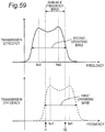
- Fig. 8 is a graph showing the characteristics of transmission efficiency versus frequency of the wireless power transmission system 10 of Fig. 1 .
- a plurality of resonators are electromagnetically coupled to each other, their resonance frequency is split into the same number of frequencies as the number of the resonators.
- the resonance frequency of the system is split into two frequencies, so-called even mode and odd mode (see: Non-Patent Documents 1 and 2).
- an even-mode resonance frequency and an odd-mode resonance frequency have different values from each other. It can be considered that the resonant condition (resonant mode) of a lower resonance frequency fo is the odd mode, and the resonant condition (resonant mode) of a higher resonance frequency fe is the even mode.
- the power transmitting coil Lt is close to the power receiving coil Lr such that they are electromagnetically coupled to each other, and two separate resonance frequencies, i.e., the odd-mode resonance frequency fo, and the even-mode resonance frequency fe higher than the odd-mode resonance frequency fo, occur.
- the two resonance frequencies fo and fe vary depending on the connection impedances to the preceding and subsequent circuits connected to the input and output portions of the power transmitting antenna 22 and the power receiving antenna 31, it does not change the fact that the resonance frequency is split into two values due to two resonators coupled to each other.
- the resonant mode of a lower resonance frequency fo of two separate resonance frequencies occurring when the power transmitting antenna 22 and the power receiving antenna 31 are coupled to each other is defined as odd mode
- the resonant mode of a higher resonance frequency fe is defined as even mode.
- the control circuit 23 of the wireless power transmitting apparatus 2 sets the frequency of high-frequency power generated by the oscillator circuit 21, i.e., transmission frequency ftr, to one of the odd-mode resonance frequency fo and the even-mode resonance frequency fe.
- Fig. 9 is a cross-sectional view showing a magnetic flux distribution in the wireless power transmission system 10 of Fig. 1 , for the case where the power transmitting antenna 22 and the power receiving antenna 31 are in an odd-mode resonant condition.
- Fig. 10 is a cross-sectional view showing a magnetic flux distribution in the wireless power transmission system 10 of Fig. 1 , for the case where the power transmitting antenna 22 and the power receiving antenna 31 are in an even-mode resonant condition.
- Figs. 9 and 10 schematically show a cross-section along line A1-A2 of Fig. 6 .
- arrows indicate the main directions of a magnetic flux.
- Fig. 9 arrows indicate the main directions of a magnetic flux.
- the transmission frequency ftr is set to the odd-mode resonance frequency fo.
- the transmission frequency ftr is set to the even-mode resonance frequency fe.
- the power transmitting antenna and the power receiving antenna are coupled to each other based on a magnetic field distribution variable according to the frequency selected as the transmission frequency ftr.
- a magnetic field inside the power transmitting coil Lt and a magnetic field inside the power receiving coil Lr occur in the same direction (in Fig. 9 , +Z direction).
- a magnetic field inside the power transmitting coil Lt and a magnetic field inside the power receiving coil Lr occur in opposite directions (in Fig. 9 , +Z direction for the power transmitting coil Lt, and -Z direction for the power receiving coil Lr).
- the magnetic flux density at the peripheral portion of the power transmitting coil Lt and the power receiving coil Lr (point B) is lower in the odd-mode resonant condition than in the even-mode resonant condition.
- a foreign object made of metal, magnetic, etc. enters near the power transmitting coil Lt or the power receiving coil Lr during power transmission of the wireless power transmission system 10
- the stronger the magnetic flux density distributed in space increases, the more eddy current flows on the surface of the metal foreign object. Therefore, the stronger the magnetic flux density increases, the higher the amount of heating on the surface of the metal foreign object increases.
- the amount of heating of the metal foreign object varies depending on the relative positional relationship among the power transmitting coil Lt, the power receiving coil Lr, and the metal foreign object, and also depending on the transmission mode of the wireless power transmission system 10 (even mode and odd mode).
- the metal foreign object when the metal foreign object is located at the central portion of the power transmitting coil Lt or the power receiving coil Lr, it is possible to suppress heating of the metal foreign object, by setting the transmission frequency ftr to the resonance frequency fe for the even-mode power transmission.
- the metal foreign object when the metal foreign object is located at the peripheral portion of the power transmitting coil Lt or the power receiving coil Lr, it is possible to suppress heating of the metal foreign object, by setting the transmission frequency ftr to the resonance frequency fo for the odd-mode power transmission.
- resonant wireless power transmission by the wireless power transmission system 10 of Fig. 1 has two transmission modes (even mode and odd mode), by which the wireless power transmission system 10 can substantially maximize transmission efficiency and ensure good transmission characteristics.
- odd mode two transmission modes
- the wireless power transmission system 10 can substantially maximize transmission efficiency and ensure good transmission characteristics.
- the wireless power transmission system 10 of Fig. 1 we analyzed temperature variations of a metal foreign object, obtained when the metal foreign object was disposed between the power transmitting coil Lt and the power receiving coil Lr at the coils' central portion, and the transmission frequency ftr was set to the resonance frequency fo for the odd-mode power transmission.
- the transmission frequency ftr was set to the resonance frequency fo for the odd-mode power transmission.
- a predetermined threshold temperature e.g., a temperature set for safety reasons, such as 45 °C. That is, this time is sufficiently longer than a cycle corresponding to the transmission frequency ftr (e.g., several 100 kHz). Therefore, even when a metal foreign object is present, and an inappropriate transmission mode not capable of suppressing heating at the position of the metal foreign object is selected, it is possible to avoid the risk of heating of the metal foreign object by changing the transmission mode to the other transmission mode before the saturation of the temperature of the metal foreign object.
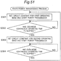
- Fig. 11 is a flowchart showing a first power transmission process performed by a control circuit 23 of a wireless power transmitting apparatus 2 of Fig. 1 .
- the control circuit 23 sets the transmission frequency ftr to the even-mode resonance frequency fe, and starts power transmission.
- the control circuit 23 determines whether or not an even-mode continuous operating time Pe has elapsed; and if YES, the process proceeds to step S103; if NO, the process repeats step S102.
- the control circuit 23 sets the transmission frequency ftr to the odd-mode resonance frequency fo, and starts power transmission.
- step S104 the control circuit 23 determines whether or not an odd-mode continuous operating time Po has elapsed; if YES, the process returns to step S101; if NO, the process repeats step S104.
- the control circuit 23 of the wireless power transmitting apparatus 2 repeatedly alternates a time interval having the continuous operating time Pe during which the transmission frequency ftr is set to the even-mode resonance frequency fe (a time interval for an even-mode transmission mode), and a time interval having the continuous operating time Po during which the transmission frequency ftr is set to the odd-mode resonance frequency fo (a time interval for an odd-mode transmission mode).
- the even-mode continuous operating time Pe may be set to be, for example, shorter than the time during which the temperature of a metal foreign object reaches a predetermined threshold temperature Tth, in the case in which the metal foreign object is present at a position where a maximum amount of heating of the metal foreign object is obtained when continuing power transmission under the condition that the power transmitting coil Lt and the power receiving coil Lr are coupled in the even mode. That is, the even-mode continuous operating time Pe may be set to be, for example, shorter than the shortest time during which the temperature of a foreign object reaches the threshold temperature Tth, when high-frequency power is transmitted at the even-mode resonance frequency and the foreign object is present near the power transmitting coil Lt or the power receiving coil Lr.
- the odd-mode continuous operating time Po may be set to be, for example, shorter than the time during which the temperature of a metal foreign object reaches the threshold temperature Tth, in the case in which the metal foreign object is present at a position where a maximum amount of heating of the metal foreign object is obtained when continuing power transmission under the condition that the power transmitting coil Lt and the power receiving coil Lr are coupled in the odd mode. That is, the odd-mode continuous operating time Po may be set to be, for example, shorter than the shortest time during which the temperature of a foreign object reaches the threshold temperature Tth, when high-frequency power is transmitted at the odd-mode resonance frequency and the foreign object is present near the power transmitting coil Lt or the power receiving coil Lr. In this case, the continuous operating times Pe and Po are set in advance based on, for example, an experimental result or a numerical simulation result of heating a foreign object during maximum power transmission.
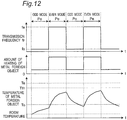
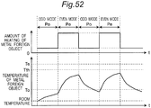
- Fig. 12 is a timing chart showing the operation of the wireless power transmission system 10 for the case where a metal foreign object is present between a power transmitting coil Lt of the power transmitting antenna 22 and a power receiving coil Lr of the power receiving antenna 31 of Fig. 1 , and the metal foreign object is present at the coils' peripheral portion.
- a metal foreign object is present between the power transmitting coil Lt and the power receiving coil Lr at the coils' peripheral portion, it is possible to suppress heating of the metal foreign object by setting the transmission frequency ftr to the resonance frequency fo, as described above (see Fig. 9 ). Referring to Fig.
- a temperature Te is the saturation temperature of the metal foreign object for the case where power is transmitted continuously in the even mode
- a temperature To is the saturation temperature of the metal foreign object for the case where power is transmitted continuously in the odd mode
- a threshold temperature Tth is the upper limit of the temperature of the foreign object, which is set in advance for safety reasons, etc. According to conventional wireless power transmission systems, when Te > Tth, the temperature of the metal foreign object is measured, and power transmission is stopped before the temperature reaches the threshold temperature Tth, thus ensuring safety.
- the even-mode continuous operating time Pe is set to be shorter than the time during which the temperature of the metal foreign object is saturated in the even mode, the temperature of the metal foreign object does not increase to the temperature Te. As a result, it is possible to continue the power transmission such that the temperature of the metal foreign object does not reach Te. Further, for example, by setting the even-mode continuous operating time Pe to be shorter than the time during which the temperature of the metal foreign object reaches the threshold temperature Tth, it is possible to continue the power transmission without increasing the temperature of the metal foreign object to the threshold temperature Tth.
- both the transmission modes in the even mode and in the odd mode may result in a small amount of heating, or otherwise, may result in a large amount of heating.
- the conventional wireless power transmission systems there is a risk of continuing power transmission in a transmission mode with a larger amount of heating, without performing power transmission in a transmission mode with a smaller amount of heating.
- the temperature of a metal foreign object increases to the threshold temperature Tth or higher, thus stopping the operation of the wireless power transmission system.
- the transmission mode is changed to one with a smaller amount of heating before the temperature of the metal foreign object is saturated to a significantly high temperature.
- a risk of heating brought about by a transmission mode with a larger amount of heating is reduced, and further, the risk can be avoided. That is, even if a metal foreign object is present near the power transmitting coil Lt or the power receiving coil Lr, it is possible to continue power transmission without immediately stopping the power transmission, while suppressing heating of the metal foreign object.
- the wireless power transmission system 10 of Fig. 1 can increase the amount of power supplied to the load apparatus 4, as compared to a conventional wireless power transmission system operating intermittently in only one transmission mode of the even mode and the odd mode, the one transmission mode resulting in a potentially larger amount of heating.
- a time shorter than the continuous operating times Po and Pe may be added to stop the wireless power transmission when changing the transmission mode.
- the power transmitting coil Lt and the power receiving coil Lr of Figs. 6 and 7 are single-layer square or circular spiral coils, the shapes of the power transmitting coil Lt and the power receiving coil Lr are not limited thereto.
- the power transmitting coil Lt and the power receiving coil Lr may have other shapes, such as a rectangle or an ellipse.
- the power transmitting coil Lt and the power receiving coil Lr may be wound in other manners, such as helical or solenoid.
- at least one of the power transmitting coil Lt and the power receiving coil Lr may be wound in multiple layers. Further, each of the power transmitting coil Lt and the power receiving coil Lr may be wound with at least one turn.
- each coil does not need to be formed as a single-layer conductive pattern, and may be configured such that a plurality of conductive patterns are stacked and connected in series with each other.
- the power transmitting coil Lt and the power receiving coil Lr of the wireless power transmission system 10 of Fig. 1 are made of, for example, a conductor having good conductivity, such as copper or silver. Since a high-frequency current mainly flows on the surface of a conductor, the surface of the conductor may be covered by a high conductivity material in order to increase transmission efficiency. In addition, in order to avoid unnecessary coupling between a plurality of wirings of the power transmitting coil Lt and the power receiving coil Lr, the surfaces of conductors of the wirings may be covered by magnetic material.
- the power transmitting coil Lt and the power receiving coil Lr may be configured using a conductor with a cross section including a central hollow portion, to reduce the weight of the power transmitting antenna 22 and the power receiving antenna 31. Further, by forming the power transmitting coil Lt and the power receiving coil Lr using a conductor with a parallel wiring structure, such as Litz wire, it is possible to reduce the conductor loss per unit length, and therefore, improve the Q factor of the resonant circuits, and achieve power transmission with higher transmission efficiency.
- wirings may be formed at once using ink printing techniques in order to reduce manufacturing costs.
- magnetic material may be disposed around the power transmitting coil Lt and/or the power receiving coil Lr. Furthermore, it is possible to set a desired coupling coefficient between the power transmitting coil Lt and the power receiving coil Lr by using an inductor with an air-core spiral structure.
- Figs. 6 and 7 show that both the power transmitting coil Lt and the power receiving coil Lr are wound in the same direction (clockwise), the power transmitting coil Lt and the power receiving coil Lr may be wound in opposite directions (clockwise and counterclockwise). In addition, both the power transmitting coil Lt and the power receiving coil Lr may be wound counterclockwise.
- the power transmitting coil Lt and the power receiving coil Lr may have different sizes or different shapes. Even when the power transmitting coil Lt and the power receiving coil Lr have the same size and the same shape, the power transmitting coil Lt and the power receiving coil Lr may have different electrical characteristics.
- the power transmitting coil Lt and the power receiving coil Lr may be provided with shields in order to prevent unnecessary radiation.
- the operation of the wireless power transmission system 10 of Fig. 1 is not impaired.
- each of the resonant capacitors Ct and Cr it is possible to use various types of capacitors, for example, a chip capacitor or a capacitor with leads.
- a capacitance between two wirings through air may serve as each of the resonant capacitors Ct and Cr.
- each of the resonant capacitors Ct and Cr is configured as an MIM capacitor, it is possible to form a capacitance circuit with relatively low loss using a well-known semiconductor process or multilayer board process.
- the transmission frequency ftr is set to, for example, 50 Hz to 300 GHz, 20 kHz to 10 GHz, 20 kHz to 20 MHz, or 20 kHz to 1 MHz.
- the transmission frequency ftr may be set to ISM band, such as 6.78 MHz and 13.56 MHz.
- the transmission frequency ftr may be set within a range up to 263 kHz so that its second harmonic does not interfere with AM radio broadcast waves, or a range up to 175 kHz so that its third harmonic does not interfere with AM radio broadcast waves, or a range up to 105 kHz so that its fifth harmonic does not interfere with AM radio broadcast waves.
- the oscillator circuit 21 of the wireless power transmission system 10 of Fig. 1 is configured using a class-D amplifier
- the configuration of the oscillator circuit 21 is not limited thereto.
- the oscillator circuit 21 may be configured using an amplifier capable of achieving high efficiency and low distortion characteristics, such as a class-E amplifier or a class-F amplifier, or may be configured using a Doherty amplifier.
- a low-pass filter or a band-pass filter may be provided to generate a sine wave with high efficiency. In this case, the low-pass filter or the band-pass filter may serve as a matching circuit.
- the oscillator circuit 21 may be a frequency converter circuit for converting a direct-current voltage from the power supply apparatus 1, into a high-frequency voltage. In any case, it is only necessary for the oscillator circuit 21 to convert inputted direct-current power into high-frequency energy and output the high-frequency energy to the power transmitting antenna 22.
- the transmission efficiency of the wireless power transmission system 10 depends on the gap g between the power transmitting antenna 22 and the power receiving antenna 31 (antenna gap), and also depends on the amount of losses in circuit elements forming the power transmitting antenna 22 and the power receiving antenna 31.
- the "antenna gap” is substantially the gap g between the power transmitting antenna 22 and the power receiving antenna 31.
- the antenna gap can be evaluated based on the size of an areas in which the power transmitting antenna 22 and the power receiving antenna 31 are disposed. In this case, the size of the areas in which the power transmitting antenna 22 and the power receiving antenna 31 are disposed corresponds to the size of an area in which a relatively smaller antenna is disclosed.
- the size is defined as the diameter of the coil.
- the size is defined as the length of one side of the coil.
- the size is defined as the length of a short side of the coil.
- the Q factors of the resonant circuits of the power transmitting antenna 22 and the power receiving antenna 31 depend on required transmission efficiency, and also depend on a coupling coefficient between the power transmitting coil Lt and the power receiving coil Lr.
- the Q factor is set to, for example, 100 or more, 200 or more, 500 or more, or 1000 or more. It is effective to user a Litz wire in order to achieve a high Q value, as described above.
- the power supply apparatus 1 of the wireless power transmission system 10 of Fig. 1 converts alternating-current power from a commercial alternating-current power supply, into direct-current power, and outputs the direct-current power to the wireless power transmission system 10, the configuration of the power supply apparatus 1 is not limited thereto.
- the power supply apparatus 1 may obtain power from an alternating-current power supply outputting an alternating-current voltage with a certain frequency, or from a direct-current power supply, such as a solar cell, and convert the power into direct-current power, and supply the direct-current power to the wireless power transmitting apparatus 2.
- a matching circuit may be connected between the oscillator circuit 21 and the power transmitting antenna 22, and a matching circuit may be connected between the power receiving antenna 31 and the load apparatus 4.
- control circuit 23 of the wireless power transmitting apparatus 2 may be integrated with the oscillator circuit 21, and configured as an integrated circuit.
- Fig. 13 is a block diagram showing a configuration of a wireless power transmission system 10a according to a first modified embodiment of the first embodiment.
- the wireless power transmission system 10a includes: a wireless power transmitting apparatus 2a connected to the power supply apparatus 1; and the power receiving antenna 31 connected to the load apparatus 4a.
- the wireless power transmitting apparatus 2a is provided with a control circuit 23a, instead of the control circuit 23 of Fig. 1 .
- the load apparatus 4a transmits a request signal notifying of its required voltage and current, to the control circuit 23a of the wireless power transmitting apparatus 2a.
- the amount of power to be transmitted from a power transmitting antenna 22 of the wireless power transmitting apparatus 2a to the power receiving antenna 31 varies depending on a change in power consumed by the load apparatus 4a.
- the control circuit 23a of the wireless power transmitting apparatus 2a adjusts the transmission frequency ftr near the even-mode resonance frequency fe or near the odd-mode resonance frequency fo, based on the voltage and current to be outputted to the load apparatus 4a, such that a desired voltage and a desired current are outputted to the load apparatus 4a.
- the frequency near the even-mode resonance frequency fe ranges from a frequency (fe - ⁇ fe) to a frequency (fe + ⁇ fe), and ⁇ fe is set to, for example, 5 % of the even-mode resonance frequency fe.
- the frequency near the odd-mode resonance frequency fo ranges from a frequency (fo - ⁇ fo) to a frequency (fo + ⁇ fo), and ⁇ fo is set to, for example, 5 % of the odd-mode resonance frequency fo.
- control circuit 23a of the wireless power transmitting apparatus 2a may adjust the transmission frequency ftr near the even-mode resonance frequency fe or near the odd-mode resonance frequency fo, based on a voltage and a current to be inputted to the power transmitting antenna 22, such that a desired voltage and a desired current are outputted to the load apparatus 4a.
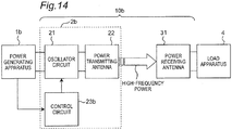
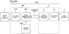
- Fig. 14 is a block diagram showing a configuration of a wireless power transmission system 10b according to a second modified embodiment of the first embodiment.
- the wireless power transmission system 10b includes: a wireless power transmitting apparatus 2b connected to a power generating apparatus 1b; and the power receiving antenna 31 connected to the load apparatus 4.
- the power generating apparatus 1b is, for example, a power supply apparatus, such as a solar cell. In this case, power outputted from the power generating apparatus 1b varies depending on the amount of sunlight received by the solar cell.
- the wireless power transmitting apparatus 2b is provided with a control circuit 23b, instead of the control circuit 23 of Fig. 1 .
- the control circuit 23b of the wireless power transmitting apparatus 2b adjusts the transmission frequency ftr near the odd-mode resonance frequency fo or near the even-mode resonance frequency fe, based on a voltage and a current outputted from the power generating apparatus 1b, so that maximum power can be obtained from the power generating apparatus 1b.
- control circuit of the wireless power transmitting apparatus may adjust the transmission frequency ftr near the even-mode resonance frequency fe or near the odd-mode resonance frequency fo, based on transmission efficiency, an output voltage, or an output current, during power transmission, so that maximum power can be obtained from the power supply apparatus.
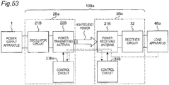
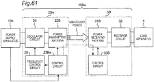
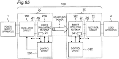
- Fig. 15 is a block diagram showing a configuration of a wireless power transmission system 10c according to a third modified embodiment of the first embodiment.
- the wireless power transmission system 10c of Fig. 15 includes: the wireless power transmitting apparatus 2 connected to the power supply apparatus 1; and a wireless power receiving apparatus 3 connected to the load apparatus 4.
- the wireless power transmission system 10c wirelessly transmits high-frequency power from the wireless power transmitting apparatus 2 to the wireless power receiving apparatus 3.
- the wireless power receiving apparatus 3 is provided with a power receiving antenna 31 and a rectifier circuit 32.
- the rectifier circuit 32 operates as a power receiving circuit for converting high-frequency power transmitted from the wireless power transmitting apparatus 2 through the power transmitting antenna 22 and the power receiving antenna 31, into direct-current output power, and supplying the direct-current output power to the load apparatus 4.
- an output impedance Zr1 for the case where the rectifier circuit 32 is seen from the output terminal of the power receiving antenna 31 is set to be substantially equal to an input impedance Zr2 for the case where the output terminal of the power receiving antenna 31 is seen from the rectifier circuit 32.
- the wireless power transmission system 10c of Fig. 15 even if a metal foreign object is present near the power transmitting coil Lt or the power receiving coil Lr, it is possible to continue power transmission without immediately stopping the power transmission, while suppressing heating of the metal foreign object.
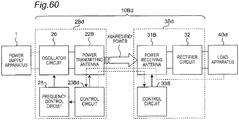
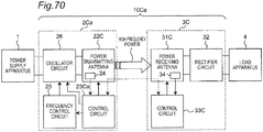
- Fig. 16 is a block diagram showing a configuration of a wireless power transmission system 10d according to a fourth modified embodiment of the first embodiment.
- the wireless power transmission system 10d includes: the wireless power transmitting apparatus 2 connected to the power supply apparatus 1; and a wireless power receiving apparatus 3d connected to the load apparatus 4.
- the wireless power receiving apparatus 3d of Fig. 16 is provided with a frequency converter circuit 32d, instead of the rectifier circuit 32 of the wireless power receiving apparatus 3c of Fig. 15 .
- the frequency converter circuit 32d converts high-frequency power transmitted from the wireless power transmitting apparatus 2 through the power transmitting antenna 22 and the power receiving antenna 31, into alternating-current power with a frequency required by the load apparatus 4, and supplies the alternating-current power to the load apparatus 4.
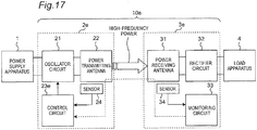
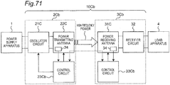
- Fig. 17 is a block diagram showing a configuration of a wireless power transmission system 10e according to a fifth modified embodiment of the first embodiment.
- the wireless power transmission system 10e includes: a wireless power transmitting apparatus 2e connected to the power supply apparatus 1; and a wireless power receiving apparatus 3e connected to the load apparatus 4.
- the wireless power transmitting apparatus 2e is provided with a control circuit 23e, instead of the control circuit 23 of Fig. 1 .
- the wireless power transmitting apparatus 2e is further provided with a sensor 24 configured to detect an abnormal condition due to a foreign object near the power transmitting coil Lt (e.g., an abnormal temperature increase resulting from heating of a metal foreign object caused by an eddy current occurring on the metal foreign object), and notify the control circuit 23e of the abnormal condition.
- an abnormal condition due to a foreign object near the power transmitting coil Lt e.g., an abnormal temperature increase resulting from heating of a metal foreign object caused by an eddy current occurring on the metal foreign object
- the wireless power receiving apparatus 3e has the configuration of the wireless power receiving apparatus 3 of Fig. 15 , and is further provided with a monitoring circuit 33 and a sensor 34.
- the sensor 34 detects an abnormal condition due to a foreign object near the power receiving coil Lr (e.g., an abnormal temperature increase resulting from heating of a metal foreign object caused by an eddy current occurring on the metal foreign object), and notifies the monitoring circuit 33 of the abnormal condition.
- the monitoring circuit 33 notifies the control circuit 23e of the wireless power transmitting apparatus 2e, of the detection result.
- the sensors 24 and 34 include, for example, detection means, such as a temperature sensor for measuring a temperature near the power transmitting coil Lr or the power receiving coil Lt, an infrared camera, or an imaging device.
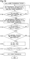
- Fig. 18 is a flowchart showing a second power transmission process performed by a control circuit 23e of a wireless power transmitting apparatus 2e of Fig. 17 .
- Steps S111 to S 114 of Fig. 18 are the same as steps S101 to S104 of Fig. 11 . If YES at step S 114, the process proceeds to step S 115.
- the control circuit 23e determines whether or not the sensor 24 or 34 has detected an abnormal condition due to a foreign object; and if YES, then at step S 116, the control circuit 23e stops power transmission to end the power transmission process; if NO, the process returns to step S111.
- control circuit 23e determines that an abnormal condition due to a foreign object has been detected.
- the second power transmission process even if a metal foreign object is present near the power transmitting coil Lt or the power receiving coil Lr, it is possible to continue power transmission without immediately stopping the power transmission, while suppressing heating of the metal foreign object, until an abnormal condition due to the foreign object is detected.
- steps S115 and S116 are performed subsequent to step S 114 in Fig. 18 , the order of the steps is not limited thereto. Steps S 115 and S 116 may be performed at any time between steps S111 and S114.
- Fig. 19 is a flowchart showing a third power transmission process performed by the control circuit 23e of the wireless power transmitting apparatus 2e of Fig. 17 .
- Steps S121 to S125 and S128 of Fig. 19 are the same as steps S 111 to S 115 and S116 of Fig. 18 .
- the control circuit 23e sets the odd-mode continuous operating time Po to be reduced by an odd-mode reduction time ⁇ Po, and sets the even-mode continuous operating time Pe to be reduced by an even-mode reduction time ⁇ Pe.
- step S127 the control circuit 23e determines whether or not the continuous operating time Po or Pe is equal to a minimum operating time Pmin or less; and if YES, then at step S128, the control circuit 23e stops power transmission to end the power transmission process; if NO, the process returns to step S121.
- the odd-mode reduction time ⁇ Po is set to, for example, 5 % of the odd-mode continuous operating time Po
- the even-mode reduction time ⁇ Pe is set to, for example, 5 % of the even-mode continuous operating time Pe.
- Heating during power transmission at one transmission mode of the even mode and the odd mode which results in a larger amount of heating, is dominant in heating of a metal foreign object. Therefore, by reducing the continuous operating time for the transmission mode with a larger amount of heating, there is a possibility to suppress the temperature of the metal foreign object under the threshold temperature Tth. According to the third power transmission process of Fig. 19 , even if a metal foreign object is detected, since the continuous operating time Pe and Po are reduced, it is possible to continue power transmission longer than that of the second power transmission process of Fig. 18 , without immediately stopping power transmission, while suppressing heating of the metal foreign object.
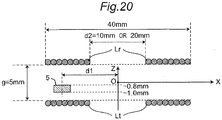
- Fig. 20 is a cross-sectional view showing configurations of a power transmitting coil Lt and a power receiving coil Lr according to an implementation example of the first embodiment.
- a simulation was done using the finite element method.
- planar circular spiral coils of a single-layer configuration were used as the power transmitting coil Lt and the power receiving coil Lr.
- the number of turns of each of the power transmitting coil Lt and the power receiving coil Lr was set to 8, the outer diameter was set to 40 mm, and the inner diameter d2 was set to 10 mm or 20 mm.
- the resonance frequency fo was set to 106 kHz
- the resonance frequency fe was set to 162.6 kHz.
- a piece of aluminum of 2 mm x 2 mm x 0.2 mm was disposed between the power transmitting coil Lt and the power receiving coil Lr.
- the output impedance Zt1 for the case where the input terminal of the power transmitting antenna 22 was seen from the output terminal of the oscillator circuit 21 was set to be substantially equal to the input impedance Zt2 for the case where the output terminal of the oscillator circuit 21 was seen from the input terminal of the power transmitting antenna 22.
- the output impedance Zr1 for the case where the load apparatus 4 was seen from the output terminal of the power receiving antenna 31 is set to be substantially equal to the input impedance Zr2 for the case where the output terminal of the power receiving antenna 31 was seen from the load apparatus 4.
- a good transmission efficiency of 90 % or more was achieved whether the transmission frequency ftr was set to either the resonance frequency fo or fe. That is, it was possible to perform power transmission equivalent in terms of input and output voltages, a current, and efficiency, whether the transmission frequency ftr was set to either the resonance frequency fo or fe.
- An eddy current generated on the surface of the metal foreign object 5 is proportional to the area of the metal foreign object 5.
- the amount of heating of the metal foreign object 5 is theoretically proportional to the square of the eddy current generated on the surface of the metal foreign object 5. Therefore, the square of a maximum value of the surface current density was evaluated as an indicator of the amount of heating.
- Fig. 21 is a graph showing the direct-current density with respect to the position of a metal foreign object 5, for the case where the inner diameter d2 of the power transmitting coil Lt and the power receiving coil Lr of Fig. 20 is 10 mm.
- the input power to the power transmitting coil Lt was set to 1 W.
- Fig. 21 shows a relationship between the position of the metal foreign object 5 and a maximum value of the surface current density on the metal foreign object 5, for the case where the transmission frequency ftr is set to the resonance frequency fo or fe.
- Fig. 21 shows a graph showing the direct-current density with respect to the position of a metal foreign object 5, for the case where the inner diameter d2 of the power transmitting coil Lt and the power receiving coil Lr of Fig. 20 is 10 mm.
- the input power to the power transmitting coil Lt was set to 1 W.
- Fig. 21 shows a relationship between the position of the metal foreign object 5 and a maximum value of the surface current density on the metal foreign object
- FIG. 21 also shows a relationship between the position of the metal foreign object 5 and the ratio of reduction of heating at the respective positions, the reduction being achieved when selecting one transmission mode capable of suppressing a larger amount of heating as compared to when selecting the other transmission mode.
- the amount of heating can be reduced by setting the transmission frequency ftr to the even-mode resonance frequency fe.
- the amount of heating can be reduced by setting the transmission frequency ftr to the odd-mode resonance frequency fo.
- Fig. 22 is a graph showing direct-current density with respect to the position of a metal foreign object 5, for the case where the inner diameter d2 of the power transmitting coil Lt and the power receiving coil Lr of Fig. 20 is 20 mm. Referring to Fig. 22 , it can be seen that when the metal foreign object 5 is present within the opening (central portion) of the power transmitting coil Lt and the power receiving coil Lr, the amount of heating can be reduced by setting the transmission frequency ftr to the even-mode resonance frequency fe, as in the case of Fig. 21 .
- the amount of heating can be reduced by setting the transmission frequency ftr to the odd-mode resonance frequency fo.
- Figs. 21 and 22 it can be seen that, not depending on the structures of the power transmitting coil Lt and the power receiving coil Lr, (1) when the metal foreign object 5 is present at the central portion of the power transmitting coil Lt and the power receiving coil Lr, the amount of heating is smaller when the transmission frequency ftr is the resonance frequency fe, than when the transmission frequency ftr is the resonance frequency fo, and (2) when the metal foreign object 5 is present at the peripheral portion of the power transmitting coil Lt and the power receiving coil Lr, the amount of heating is smaller when the transmission frequency ftr is the resonance frequency fo, than when the transmission frequency ftr is the resonance frequency fe.
- the wireless power transmission system 10 has two transmission modes (even mode and odd mode) capable of ensuring good transmission characteristics, and can suppress heating regardless of the position of the metal foreign object 5, by selecting one of the transmission modes.
- Fig. 23 is a graph showing changes in the temperature of the metal foreign object 5 of aluminum with a size of 1 cm x 1 cm x 1 mm, for the case where the metal foreign object 5 is present between the power transmitting coil Lt and the power receiving coil Lr of Fig. 20 at the coils' central portion, while continuing power transmission at the odd-mode resonance frequency fo.
- the input power to the power transmitting coil Lt was set to 3 W.
- it has been found that the temperature of the metal foreign object 5 is not saturated immediately after starting the transmission, and it takes several tens of minutes or more for the temperature of the metal foreign object 5 to be saturated.
- the temperature of the metal foreign object 5 increased by 35 degrees from room temperature in 30 minutes after starting the transmission, it increased by only 30 degrees in 20 minutes, 28 degrees in 15 minutes, 25 degrees in 10 minutes, 20 degrees in 5 minutes, 15 degrees in 3 minutes, 10 degrees in 90 seconds, and 5 degrees in 45 seconds.
- an elapsed time of, for example, 60 seconds corresponds to 6360000 times of the transmission cycle for the case in which the transmission frequency ftr is set to the resonance frequency fo.
- the time required for the temperature of the metal foreign object 5 or the housing close to the metal foreign object 5 to reach the predetermined threshold temperature Tth is a very long as compared to the cycle of transmission energy, even if a "wrong transmission mode" resulting in a serious amount of heating of the metal foreign object 5 is selected.
- the threshold temperature Tth is 45 °C
- the odd-mode continuous operating time Po may be set to less than 5 minutes.
- the two transmission modes have different maximum increase rates of the temperature of the metal foreign object 5 for the case where the metal foreign object 5 is present
- the surface current density for the case where the transmission frequency ftr is set to the resonance frequency fo (odd mode) can be 1220 mA/m
- the surface current density for the case where the transmission frequency ftr is set to the resonance frequency fe (even mode) can be, at most, 840 mA/m.
- the amount of heating for the case where the transmission frequency ftr is set to the resonance frequency fe is only 47 % of the amount of heating for the case where the transmission frequency ftr is set to the resonance frequency fo. Therefore, even if the even-mode continuous operating time Pe is set to 1 to 2.1 times of the odd-mode continuous operating time Po, an integrated amount of heating during the even-mode operation does not exceed a maximum integrated amount of heating during the odd-mode operation. Further, taking the natural dissipation of heat from the metal foreign object 5 into consideration, there may be a case in which the even-mode continuous operating time Pe can be set to 2.1 times or more of the odd-mode continuous operating time Po.
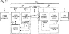
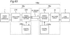
- Fig. 24 is a block diagram showing a schematic configuration of a wireless power transmission system 10A according to a second embodiment.
- the wireless power transmission system 10A includes: a wireless power transmitting apparatus 2A connected to the power supply apparatus 1; and a wireless power receiving apparatus 3A connected to the load apparatus 4.
- the wireless power transmission system 10A wirelessly transmits high-frequency power from the wireless power transmitting apparatus 2A to the wireless power receiving apparatus 3A.
- the wireless power transmitting apparatus 2A is provided with a power transmitting circuit 21A, the power transmitting antenna 22, a control circuit 23A, and the sensor 24.
- the power transmitting antenna 22 of the wireless power transmitting apparatus 2A is configured in a manner similar to that of the power transmitting antenna 22 of Fig. 2 or the power transmitting antenna 22a of Fig. 4 .
- the power transmitting circuit 21A is connected to the power supply apparatus 1, and generates, from input power, an output voltage (high-frequency power) with a variable frequency (e.g., 100 to 200 kHz, etc.) using pulse width modulation, and supplies the output voltage to the power transmitting antenna 22, under the control of the control circuit 23A.
- the power transmitting circuit 21A transmits power at a certain frequency to the wireless power receiving apparatus 3A through the power transmitting antenna 22.
- the control circuit 23A controls the start and stop of power transmission performed by the power transmitting circuit 21A, and also controls the frequency of an output voltage from the power transmitting circuit 21A.
- the sensor 24 detects an abnormal condition due to a foreign object near the power transmitting coil Lt of the power transmitting antenna 22 (e.g., an abnormal temperature increase resulting from heating of a metal foreign object caused by an eddy current occurring on the metal foreign object), and notifies the control circuit 23A of the abnormal condition.
- the sensor 24 includes, for example, a temperature sensor.
- the wireless power receiving apparatus 3A includes the power receiving antenna 31, a power receiving circuit 32A, a monitoring circuit 33A, and the sensor 34.
- the power receiving antenna 31 of the wireless power receiving apparatus 3A is configured in a manner similar to that of the power receiving antenna 31 of Fig. 3 or the power receiving antenna 31a of Fig. 5 .
- the power receiving circuit 32A receives power transmitted from the wireless power transmitting apparatus 2A through the power receiving antenna 31, and supplies the power to the load apparatus 4.
- the power receiving circuit 32A transmits a signal requesting to stop power transmission, to the control circuit 23A of the wireless power transmitting apparatus 2A through the power receiving antenna 31 and the power transmitting antenna 22.
- the sensor 34 detects an abnormal condition due to a foreign object near the power receiving coil Lr of the power receiving antenna 31, and notifies the monitoring circuit 33A of the abnormal condition.
- the sensor 34 includes, for example, a temperature sensor.
- the monitoring circuit 33A transmits a signal indicating the occurrence of the abnormal condition, to the control circuit 23A of the wireless power transmitting apparatus 2A through the power receiving antenna 31 and the power transmitting antenna 22.
- At least one temperature estimation means is required to estimate the temperature of a foreign object near the power transmitting coil or the power receiving coil, in which heating of the metal foreign object being problematic.
- Various temperature estimation means can be used to estimate the temperature. For example, it is possible to use a method of directly measuring a temperature using a temperature sensor, such as a thermistor, and a method of measuring transmission efficiency between the wireless power transmitting apparatus 2A and the wireless power receiving apparatus 3A, calculating loss power, and estimating the temperature of a heated foreign object from the loss power.
- NFC Near Field Communication
- modulated radio signals may be used in order to transmit signals from the power receiving circuit 32A or the monitoring circuit 33A of the wireless power receiving apparatus 3A to the control circuit 23A of the wireless power transmitting apparatus 2A through the power receiving antenna 31 and the power transmitting antenna 22.
- additional antennas provided to the wireless power receiving apparatus 3A and the wireless power transmitting apparatus 2A, other than the power receiving antenna 31 and the power transmitting antenna 22, may be used in order to transmit signals from the power receiving circuit 32A or the monitoring circuit 33A of the wireless power receiving apparatus 3A to the control circuit 23A of the wireless power transmitting apparatus 2A.
- the power transmitting antenna 22 and the power receiving antenna 31 are provided close to each other so as to be electromagnetically coupled to each other.
- one of the power transmitting antenna and the power receiving antenna is provided with a coil and a capacitor connected in series, and the other is provided with a coil and a capacitor connected in parallel. Therefore, it is possible to use a combination of the power transmitting antenna 22 of Fig. 2 and the power receiving antenna 31a of Fig. 5 , or a combination of the power transmitting antenna 22a of Fig. 3 and the power receiving antenna 31 of Fig. 4 .
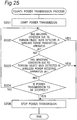
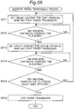
- Fig. 25 is a flowchart showing a fourth power transmission process performed by the control circuit 23A of the wireless power transmitting apparatus 2A of Fig. 24 .
- the fourth power transmission process shows a comparison example in which power transmission is stopped when a metal foreign object is detected.
- the control circuit 23A instructs the power transmitting circuit 21A to start power transmission.
- the control circuit 23A determines whether or not an abnormal condition due to a foreign object has been detected in the wireless power transmitting apparatus 2A.
- the abnormal condition due to a foreign object is, for example, an abnormal temperature increase resulting from heating of a metal foreign object caused by an eddy current occurring on the metal foreign object, as described above.
- the control circuit 23A determines it to be an abnormal condition. If YES at step S202, the process proceeds to step S205, and if NO at step S202, the process proceeds to step S203. At step S203, the control circuit 23A determines whether or not an abnormal condition due to a foreign object has been detected in the wireless power receiving apparatus 3A, based on a signal received from the monitoring circuit 33A of the wireless power receiving apparatus 3A.
- the control circuit 23A determines it to be an abnormal condition. If YES at step S203, the process proceeds to step S205, and if NO at step S203, the process proceeds to step S204.
- the control circuit 23A determines whether or not the power transmission is to be stopped. For example, the control circuit 23A stops the power transmission, when receiving a signal requesting to stop the power transmission, from the power receiving circuit 32A of the wireless power receiving apparatus 3A, or when detecting that the wireless power receiving apparatus 3A has been removed, using a further sensor (not shown). If YES at step S204, the process proceeds to step S205, and if NO at step S204, the process returns to step S202. At step S205, the control circuit 23A instructs the power transmitting circuit 21A to stop the power transmission.
- Fig. 26 is a schematic diagram for explaining temperature changes obtained when performing the fourth power transmission process of Fig. 25 . It is possible to suppress overheating of the metal foreign object by stopping power transmission when the temperature near the power transmitting coil Lt or the power receiving coil Lr is equal to the threshold Tc or higher. However, according to the fourth power transmission process, power transmission cannot be resumed unless the user removes the metal foreign object.
- Fig. 27 is a flowchart showing a fifth power transmission process performed by the control circuit 23A of the wireless power transmitting apparatus 2A of Fig. 24 .
- the control circuit 23A changes the frequency of the high-frequency power generated by the power transmitting circuit 21A to the other of the odd-mode resonance frequency fo and the even-mode resonance frequency fe. Specifically, at step S211 of Fig.
- the control circuit 23A instructs the power transmitting circuit 21A to set the transmission frequency ftr to the odd-mode resonance frequency fo and start power transmission.
- the control circuit 23A determines whether or not an abnormal condition due to a foreign object has been detected in the wireless power transmitting apparatus 2A; if YES, the process proceeds to step S214; if NO, the process proceeds to step S213.
- the control circuit 23A determines whether or not an abnormal condition due to a foreign object has been detected in the wireless power receiving apparatus 3A; if YES, the process proceeds to step S214; if NO, the process proceeds to step S215.
- the control circuit 23A instructs the power transmitting circuit 21A to set the transmission frequency ftr to the even-mode resonance frequency fe and start power transmission.
- the transmission frequency ftr is changed, a magnetic field distribution near the power transmitting coil Lt and the power receiving coil Lr changes, and therefore, the amount of an eddy current generated on the metal foreign object changes.
- the control circuit 23A instructs the power transmitting circuit 21A to stop the power transmission.
- step S215 the control circuit 23A determines whether or not an abnormal condition due to a foreign object has been detected in the wireless power transmitting apparatus 2A; if YES, the process proceeds to step S218; if NO, the process proceeds to step S216.
- step S216 the control circuit 23A determines whether or not an abnormal condition due to a foreign object has been detected in the wireless power receiving apparatus 3A; if YES, the process proceeds to step S218; if NO, the process proceeds to step S217.
- step S217 the control circuit 23A determines whether or not the power transmission is to be stopped; and if YES, the process proceeds to step S218; if NO, the process returns to step S215.
- step S218 the control circuit 23A instructs the power transmitting circuit 21A to stop the power transmission.
- Fig. 28 is a schematic diagram for explaining temperature changes obtained when performing the fifth power transmission process of Fig. 27 .
- the fifth power transmission process even when a metal foreign object is detected near the power transmitting coil Lt or the power receiving coil Lr, it is possible to continue power transmission without immediately stopping the power transmission, while suppressing heating of the metal foreign object.
- Fig. 28 schematically shows the case in which the power transmission is temporarily stopped when an abnormal condition due to a foreign object is detected
- the transmission frequency ftr may be immediately changed from the odd-mode resonance frequency fo to the even-mode resonance frequency fe, without stopping the power transmission.
- the threshold Tc used by the control circuit 23A to determine the occurrence of an abnormal condition due to a foreign object is not limited to 90 ° C, and may be other temperatures. In addition, different thresholds Tc may be used for the wireless power transmitting apparatus 2A and for the wireless power receiving apparatus 3A.
- control circuit 23A of the wireless power transmitting apparatus 2A obtains information on transmitting power, from the power transmitting circuit 21A.
- the monitoring circuit 33A of the wireless power receiving apparatus 3A obtains information indicating the amount of received power, from the power receiving circuit 32A, and transmits a signal including the information to the control circuit 23A of the wireless power transmitting apparatus 2A through the power receiving antenna 31 and the power transmitting antenna 22.
- the control circuit 23A determines that an abnormal condition due to a foreign object near the power transmitting coil Lt or the power receiving coil Lr has occurred.
- control circuit 23A may omit steps S223 and S226 to determine whether or not an abnormal condition due to a foreign object has been detected in the wireless power receiving apparatus 3A.
- Fig. 29 is a flowchart showing a sixth power transmission process performed by the control circuit 23A of the wireless power transmitting apparatus 2A of Fig. 24 .
- the transmission frequency ftr is set to the odd-mode resonance frequency fo to start the power transmission (step S211), and then, when an abnormal condition due to a foreign object is detected, the transmission frequency ftr is changed to the even-mode resonance frequency fe (step S214).
- the transmission frequency ftr may be set to the even-mode resonance frequency fe to start the power transmission (step S221), and then, when an abnormal condition due to a foreign object is detected, the transmission frequency ftr may be changed to the odd-mode resonance frequency fo (step S224).
- Steps S221 to S228 of Fig. 29 are the same as steps S211 to S218 of Fig. 27 , except for steps S221 and S224.
- the sixth power transmission process even when a metal foreign object is detected near the power transmitting coil Lt or the power receiving coil Lr, it is possible to continue power transmission without immediately stopping the power transmission, while suppressing heating of the metal foreign object, in a manner similar to that of the fifth power transmission process.
- Fig. 30 is a flowchart showing a seventh power transmission process performed by the control circuit 23A of the wireless power transmitting apparatus 2A of Fig. 24 .
- At least one of the sensors 24 and 34 of Fig. 24 may include a position sensor configured to detect the position of a foreign object near the power transmitting coil Lt or the power receiving coil Lr, in addition to a temperature sensor.
- a position sensor configured to detect the position of a foreign object near the power transmitting coil Lt or the power receiving coil Lr, in addition to a temperature sensor.
- the position sensor includes, for example, an optical sensor, a millimeter-wave radar, a magnetic sensor, etc.
- a magnetic sensor When a magnetic sensor is used as the position sensor, a magnetic field distribution for the case where a metal foreign object is not present is measured and stored in advance, and then, the position of a metal foreign object is detected by detecting a change with respect to the stored magnetic field distribution.
- a foreign object is detected before starting power transmission, and a transmission frequency ftr is selected according to the position of the detected foreign object.
- a transmission frequency ftr is selected according to the position of the detected foreign object.
- the magnetic flux density at the peripheral portion of the power transmitting coil Lt and the power receiving coil Lr (point B) is lower in the odd-mode resonant condition than in the even-mode resonant condition.
- power transmission is started at the even-mode resonance frequency fe when a foreign object is present at the central portion of the power transmitting coil Lt and the power receiving coil Lr (point A), and on the other hand, power transmission is started at the odd-mode resonance frequency fo when a foreign object is present at the peripheral portion of the power transmitting coil Lt and the power receiving coil Lr (point B).
- the control circuit 23A When the control circuit 23A detects a foreign object at the central portion of the power transmitting coil Lt and the power receiving coil Lr, the control circuit 23A causes the power transmitting circuit 21A to generate high-frequency power at the even-mode resonance frequency fe, and start transmission of the high-frequency power from the wireless power transmitting apparatus 2A to the wireless power receiving apparatus 3A.
- the control circuit 23A detects a foreign object at the peripheral portion of the power transmitting coil Lt and the power receiving coil Lr, the control circuit 23A causes the power transmitting circuit 21A to generate high-frequency power at the odd-mode resonance frequency fo, and start transmission of the high-frequency power from the wireless power transmitting apparatus 2A to the wireless power receiving apparatus 3A.
- the control circuit 23A determines whether or not a foreign object has been detected. If a foreign object is present at the peripheral portion of the power transmitting coil Lt and the power receiving coil Lr, or if a foreign object has not been detected, the process proceeds to step S232. If a foreign object is present at the central portion of the power transmitting coil Lt and the power receiving coil Lr, the process proceeds to step S233. At step S232, the control circuit 23A instructs the power transmitting circuit 21A to set the transmission frequency ftr to the odd-mode resonance frequency fo and start power transmission. At step S233, the control circuit 23A instructs the power transmitting circuit 21A to set the transmission frequency ftr to the even-mode resonance frequency fe and start power transmission.
- step S234 the control circuit 23A determines whether or not an abnormal condition due to a foreign object in has been detected in the wireless power transmitting apparatus 2A; if YES, the process proceeds to step S237; if NO, the process proceeds to step S235.
- step S235 the control circuit 23A determines whether or not an abnormal condition due to a foreign object has been detected in the wireless power receiving apparatus 3A; if YES, the process proceeds to step S237; if NO, the process proceeds to step S236.
- step S236 the control circuit 23A determines whether or not the power transmission is to be stopped; if YES, the process proceeds to step S237; if NO, the process returns to step S234.
- step S237 the control circuit 23A instructs the power transmitting circuit 21A to stop the power transmission.
- the seventh power transmission process even when a metal foreign object is detected near the power transmitting coil Lt or the power receiving coil Lr before starting power transmission, it is possible to start the power transmission while suppressing heating of the metal foreign object.
- Fig. 31 is a flowchart showing an eighth power transmission process performed by the control circuit 23A of the wireless power transmitting apparatus 2A of Fig. 24 .
- the seventh power transmission process may be combined with the fifth and sixth power transmission processes.
- the control circuit 23A detects a foreign object at the central portion of the power transmitting coil Lt and the power receiving coil Lr, the control circuit 23A causes the power transmitting circuit 21A to generate high-frequency power at the even-mode resonance frequency fe, and start transmission of the high-frequency power from the wireless power transmitting apparatus 2A to the wireless power receiving apparatus 3A.
- the control circuit 23A When the control circuit 23A detects a foreign object at the peripheral portion of the power transmitting coil Lt and the power receiving coil Lr, the control circuit 23A causes the power transmitting circuit 21A to generate high-frequency power at the odd-mode resonance frequency fo, and start transmission of the high-frequency power from the wireless power transmitting apparatus 2A to the wireless power receiving apparatus 3A.
- the control circuit 23A determines whether or not a foreign object has been detected. If a foreign object is present at the peripheral portion of the power transmitting coil Lt and the power receiving coil Lr, or if a foreign object has not been detected, the process proceeds to step S242. If a foreign object is present at the central portion of the power transmitting coil Lt and the power receiving coil Lr, the process proceeds to step S243.
- the control circuit 23A performs the fifth power transmission process of Fig. 27 .
- the control circuit 23A performs the sixth power transmission process of Fig. 29 .
- the eighth power transmission process even when a metal foreign object is detected near the power transmitting coil Lt or the power receiving coil Lr before starting power transmission, it is possible to start the power transmission while suppressing heating of the metal foreign object. Further, even when an abnormal condition due to a foreign object near the power transmitting coil Lt or the power receiving coil Lr occurs, it is possible to continue the power transmission without immediately stopping the power transmission, while suppressing heating of the metal foreign object.
- Fig. 32 is a block diagram showing a schematic configuration of a wireless power transmission system 10Aa according to a modified embodiment of the second embodiment.
- the wireless power transmission system 10Aa of Fig. 32 includes: a wireless power transmitting apparatus 2Aa connected to the power supply apparatus 1; and the wireless power receiving apparatus 3A connected to the load apparatus 4.
- the wireless power transmitting apparatus 2Aa is provided with a power transmitting antenna 22Aa and a control circuit 23Aa, instead of the power transmitting antenna 22 and the control circuit 23A of the wireless power transmitting apparatus 2A of Fig. 24 .
- Fig. 33 is a circuit diagram showing a configuration of the power transmitting antenna 22Aa of Fig. 32 .
- the power transmitting antenna 22Aa is provided with a power transmitting coil Lt, and a capacitor CtAa having a variable capacitance.
- the control circuit 23Aa operates in a manner similar to that of the control circuit 23A of Fig. 24 , and in addition, controls the capacitance of the capacitor CtAa.
- Fig. 34 is a schematic diagram showing a change in the characteristics of transmission efficiency versus frequency of the wireless power transmission system 10Aa, obtained when changing the capacitance of the capacitor CtAa of Fig. 32 .
- the capacitor CtAa and the power transmitting coil Lt forms a plurality of LC resonators, each of the plurality of resonators corresponding to one of the plurality of capacitances of the capacitor CtAa.
- Each of the plurality of LC resonators has an odd-mode resonance frequency and an even-mode resonance frequency. Therefore, for example, as shown in Fig.
- an LC resonator when the capacitor CtAa has a first capacitance, an LC resonator has resonance frequencies fo and fe, and when the capacitor CtAa has a second capacitance, an LC resonator has resonance frequencies fo' and fe'.
- the resonance frequency fe' is configured to be equal to the resonance frequency fo, it is possible to change the transmission mode between the even mode ( Fig. 4 ) and the odd mode ( Fig. 5 ) by changing the capacitance of the capacitor CtAa, without changing the frequency of high-frequency power generated by the power transmitting circuit 21A (transmission frequency ftr).
- Fig. 35 is a flowchart showing a ninth power transmission process performed by the control circuit 23Aa of the wireless power transmitting apparatus 2Aa of Fig. 32 .
- the control circuit 23Aa instructs the power transmitting circuit 21A to start power transmission. This step is, for example, step S214 of Fig. 27 , or step S224 of Fig. 29 .
- the control circuit 23Aa determines whether or not an abnormal condition due to a foreign object has been detected in the wireless power transmitting apparatus 2Aa; if YES, the process proceeds to step S254; if NO, the process proceeds to step S253.
- the control circuit 23Aa determines whether or not an abnormal condition due to a foreign object has been detected in the wireless power receiving apparatus 3A; and if YES, the process proceeds to step S254; if NO, the process proceeds to step S256.
- the control circuit 23Aa changes the capacitance of the capacitor CtAa.
- the control circuit 23Aa instructs the power transmitting circuit 21A to start power transmission at a frequency equal to a changed resonance frequency of an LC resonator corresponding to the changed capacitance.
- step S256 the control circuit 23Aa determines whether or not an abnormal condition due to a foreign object has been detected in the wireless power transmitting apparatus 2Aa; and if YES, the process proceeds to step S259; if NO, the process proceeds to step S257.
- step S257 the control circuit 23Aa determines whether or not an abnormal condition due to a foreign object has been detected in the wireless power receiving apparatus 3A; if YES, the process proceeds to step S259; if NO, the process proceeds to step S258.
- step S258 the control circuit 23Aa determines whether or not the power transmission is to be stopped; if YES, the process proceeds to step S259; if NO, the process returns to step S256.
- step S259 the control circuit 23Aa instructs the power transmitting circuit 21A to stop the power transmission.
- the capacitor CtAa may have three or more different capacitances.
- the control circuit 23Aa changes the transmission frequency ftr of the power transmitting circuit 21A to another frequency of the plurality of odd-mode resonance frequencies and the plurality of even-mode resonance frequencies.
- the control circuit 23Aa causes the power transmitting circuit 21A to stop the transmission of high-frequency power.
- the ninth power transmission process even when a metal foreign object is detected near the power transmitting coil Lt or the power receiving coil Lr, it is possible to continue power transmission without immediately stopping the power transmission, while suppressing heating of the metal foreign object.
- the frequency of an output voltage generated by the power transmitting circuit 21A is not limited to 100 to 200 kHz, and a frequency of 200 kHz or higher or a frequency of 100 kHz or lower may be used.
- the power transmitting coil Lt and the power receiving coil Lr of Fig. 20 were used.
- a piece of aluminum of 2 x 5 x 0.2 mm was disposed between the power transmitting coil Lt and the power receiving coil Lr.
- Fig. 36 is a graph showing direct-current density with respect to the position of the metal foreign object 5, for the case where the inner diameter d2 of the power transmitting coil Lt and the power receiving coil Lr is 20 mm.
- Fig. 37 is a graph showing direct-current density with respect to the position of the metal foreign object 5, for the case where the inner diameter d2 of the power transmitting coil Lt and the power receiving coil Lr is 10 mm.
- the horizontal axis of each graph represents a distance d from the center O of the power transmitting coil Lt and the power receiving coil Lr to the metal foreign object 5.
- the vertical axis of each graph represents surface current density.
- the total amount of surface current is obtained by multiplying the surface current density by the area of the metal foreign object 5 (2 x 5 mm 2 ). According to Figs. 36 and 37 , it can be seen that, not depending on the structures of the power transmitting coil Lt and the power receiving coil Lr, (1) when the metal foreign object 5 is present at the central portion of the power transmitting coil Lt and the power receiving coil Lr, the amount of heating is smaller at the even-mode resonance frequency fe than at the odd-mode resonance frequency fo, and (2) when the metal foreign object 5 is present at the peripheral portion of the power transmitting coil Lt and the power receiving coil Lr, the amount of heating is smaller at the odd-mode resonance frequency fo than at the even-mode resonance frequency fe.
- Fig. 38 is a block diagram showing a configuration of a wireless power transmission system 10B according to a third embodiment.
- the wireless power transmission system 10B includes: a wireless power transmitting apparatus 2B connected to the power supply apparatus 1; and a wireless power receiving apparatus 3B connected to the load apparatus 4.
- the wireless power transmission system 10B wirelessly transmits high-frequency power from the wireless power transmitting apparatus 2B to the wireless power receiving apparatus 3B.
- the wireless power transmitting apparatus 2B is provided with an oscillator circuit 21B, a power transmitting antenna 22B, and a control circuit 23B.
- the oscillator circuit 21B operates as a power transmitting circuit for generating high-frequency power from inputted direct-current power, and outputting the high-frequency power to the power transmitting antenna 22B.
- the oscillator circuit 21B is provided with: a pulse generator for generating a pulse sequence with a transmission frequency ftr; and a class-D amplifier including a switching element operable according to the pulse sequence.
- the oscillator circuit 21B generates high-frequency power with the transmission frequency ftr.
- the power transmitting antenna 22B includes an LC resonant circuit having at least one of a variable inductance and a variable capacitance.
- the control circuit 23B of the wireless power transmitting apparatus 2B changes at least one of the inductance and the capacitance of the power transmitting antenna 22B.
- the wireless power receiving apparatus 3B is provided with a power receiving antenna 31B, a rectifier circuit 32, and a control circuit 33B.
- the power receiving antenna 31B includes an LC resonant circuit having at least one of a variable inductance and a variable capacitance.
- the power receiving antenna 31B is electromagnetically coupled to the power transmitting antenna 22B.
- the control circuit 33B of the wireless power receiving apparatus 3B changes at least one of the inductance and the capacitance of the power receiving antenna 31B, under the control of the control circuit 23B of the wireless power transmitting apparatus 2B.
- the rectifier circuit 32 operates as a power receiving circuit for converting high-frequency power transmitted from the wireless power transmitting apparatus 2B through the power transmitting antenna 22B and the power receiving antenna 31B, into direct-current output power, and supplying the direct-current output power to the load apparatus 4.
- the control circuit 23B of the wireless power transmitting apparatus 2B transmits a control signal for changing at least one of the inductance and the capacitance of the power receiving antenna 31B, to the control circuit 33B of the wireless power receiving apparatus 3B, for example, through the power transmitting antenna 22B and the power receiving antenna 31B.
- the control circuit 23B of the wireless power transmitting apparatus 2B may transmit the control signal to the control circuit 33B of the wireless power receiving apparatus 3B through a communication path (not shown) different from the power transmitting antenna 22B and the power receiving antenna 31B.
- a system of the power transmitting antenna 22B and the power receiving antenna 31B electromagnetically coupled to each other has an operating band including two resonance frequencies corresponding to an odd-mode resonant condition and an even-mode resonant condition, respectively (see Fig. 8 ).
- an even-mode resonance frequency fe is higher than an odd-mode resonance frequency fo.
- the transmission efficiency of the wireless power transmission system 108 can be maximized by setting the transmission frequency ftr to the resonance frequency fo or fe.
- the operating band of the system of the power transmitting antenna 22B and the power receiving antenna 31B electromagnetically coupled to each other is associated with the circuit constants of the wireless power transmitting apparatus 2B (e.g., the inductance and the capacitance of the power transmitting antenna 22B) and the circuit constants of the wireless power receiving apparatus 3B (e.g., the inductance and the capacitance of the power receiving antenna 31B).
- the control circuit 23B of the wireless power transmitting apparatus 2B sets at least one of the circuit constant of the wireless power transmitting apparatus 2B and the circuit constant of the wireless power receiving apparatus 3B, such that the operating band of the system of the power transmitting antenna 22B and the power receiving antenna 31B electromagnetically coupled to each other is set to one of the first and second operating bands.
- Fig. 39 is a circuit diagram showing a configuration of a power transmitting antenna 22Ba according to a first example of the power transmitting antenna 22B of Fig. 38 .
- the power transmitting antenna 22Ba of Fig. 39 is an LC series resonant circuit including a power transmitting coil Lt1 and a resonant capacitor Ct1 connected in series, and the LC series resonant circuit having a resonance frequency fT.
- the resonant capacitor Ct1 has a capacitance variable under the control of the control circuit 23B of the wireless power transmitting apparatus 2B.
- Fig. 40 is a circuit diagram showing a configuration of a power transmitting antenna 22Bb according to a second example of the power transmitting antenna 22B of Fig. 38 .
- the power transmitting antenna 22Bb of Fig. 40 is an LC series resonant circuit including a power transmitting coil Lt2 and a resonant capacitor Ct2 connected in series, and the LC series resonant circuit has a resonance frequency fT.
- the power transmitting coil Lt2 has an inductance variable under the control of the control circuit 23B of the wireless power transmitting apparatus 2B.
- Fig. 41 is a circuit diagram showing a configuration of a power receiving antenna 31Ba according to a first example of the power receiving antenna 31B of Fig. 38 .
- the power receiving antenna 31Ba of Fig. 41 is an LC parallel resonant circuit including a power receiving coil Lr1 and a resonant capacitor Cr1 connected in parallel, and the LC parallel resonant circuit having a resonance frequency fR.
- the resonant capacitor Cr1 has a capacitance variable under the control of the control circuit 33B of the wireless power receiving apparatus 3B.
- Fig. 42 is a circuit diagram showing a configuration of a power receiving antenna 31Bb according to a second example of the power receiving antenna 31B of Fig. 38 .
- the 42 is an LC parallel resonant circuit including a power receiving coil Lr2 and a resonant capacitor Cr2 connected in parallel, and the LC parallel resonant circuit having a resonance frequency fR.
- the power receiving coil Lr2 has an inductance variable under the control of the control circuit 33B of the wireless power receiving apparatus 3B.
- the resonance frequency fT of the power transmitting antenna 22B changes by the control circuit 23B of the wireless power transmitting apparatus 2B which changes the inductance or the capacitance of the power transmitting antenna 22B (22Ba and 22Bb).
- the resonance frequency fR of the power receiving antenna 31B changes by the control circuit 33B of the wireless power receiving apparatus 3B which changes the inductance or the capacitance of the power receiving antenna 31B (31Ba and 31Bb).
- the control circuit 23B of the wireless power transmitting apparatus 2B can set the operating band of the system of the power transmitting antenna 22B and the power receiving antenna 31B electromagnetically coupled to each other, to one of the first and second operating bands, by changing one of the inductance and the capacitance of the power transmitting antenna 22B and the power receiving antenna 31B.
- the power transmitting antenna 22B is an LC series resonant circuit and the power receiving antenna 31B is an LC parallel resonant circuit
- the LC parallel resonant circuit of Fig. 41 or 42 may be used as the power transmitting antenna 22B.
- the LC series resonant circuit of Fig. 39 or 40 may be used as the power receiving antenna 31B.
- Both the power transmitting antenna 22B and the power receiving antenna 31B may be the LC series resonant circuit of Fig. 39 or 40 , or may be the LC parallel resonant circuit of Fig. 41 or 42 .
- the power transmitting antenna 22B may have both a variable inductance and a variable capacitance.
- the control circuit 23B of the wireless power transmitting apparatus 2B changes the inductance and the capacitance of the power transmitting antenna 22B.
- the power receiving antenna 31B may also have both a variable inductance and a variable capacitance.
- the control circuit 33B of the wireless power receiving apparatus 3B changes the inductance and the capacitance of the power receiving antenna 31B, under the control of the control circuit 23B of the wireless power transmitting apparatus 2B.
- each of the power transmitting antenna 22B and the power receiving antenna 31B may be a self-resonant circuit using its wire's parasitic capacitance.
- Fig. 43 is a circuit diagram showing configurations of a power transmitting antenna 22Bc and a power receiving antenna 31Bc according to a third example of the power transmitting antenna 22B and the power receiving antenna 31B of Fig. 38 .
- the circuit constants of the wireless power transmitting apparatus 2B and the circuit constants of the wireless power receiving apparatus 3B are not limited to the inductances and the capacitances of the power transmitting antenna 22B and the power receiving antenna 31B.
- the circuit constants of the wireless power transmitting apparatus 2B and the circuit constants of the wireless power receiving apparatus 3B include a coupling coefficient "k" between the power transmitting antenna 22B and the power receiving antenna 31B.
- the control circuit 23B of the wireless power transmitting apparatus 2B can set the operating band of the system of the power transmitting antenna 22B and the power receiving antenna 31B electromagnetically coupled to each other, to one of the first and second operating bands, by changing the coupling coefficient itself between the power transmitting antenna 22B and the power receiving antenna 31B, instead of changing the inductances and the capacitances of the power transmitting antenna 22B and the power receiving antenna 31B.
- Fig. 44 is a perspective view showing an implementation example of the power transmitting antenna 22Ba of Fig. 39 and the power receiving antenna 31Ba of Fig. 41 .
- the power transmitting antenna 22Ba and the power receiving antenna 31Ba of Fig. 44 are configured in a manner similar to that of the power transmitting antenna 22 and the power receiving antenna 31 of Fig. 6 , except that resonant capacitors have variable capacitances.
- Fig. 45 is a circuit diagram showing an implementation example of the resonant capacitor Ct1 of the power transmitting antenna 22Ba of Fig. 39 .
- the resonant capacitor Ct1 has a variable capacitance.
- the resonant capacitor Ct1 has a combined capacitance of the capacitances of a plurality of capacitors C1 and C2 connected in parallel. At least a part of the plurality of capacitors C1 and C2 (in Fig. 45 , the capacitor C2) is connected with a high-frequency switch SW1 in series, the high-frequency switch SW1 being operable under the control of the control circuit 23B of the wireless power transmitting apparatus 2B.
- the resonant capacitor Cr1 of Fig. 41 is also configured in a manner similar to that of the resonant capacitor Ct1 of Fig. 45 .
- the capacitances of the resonant capacitors Ct1 and Cr1 may be changed by other methods.
- an element having a capacitance variable depending on an applied voltage may be used as the resonant capacitor Ct1, or as one of the plurality of capacitors included in the resonant capacitor Ct1.
- Fig. 46 is a perspective view showing a first implementation example of the power transmitting coil Lt2 of the power transmitting antenna 22Bb of Fig. 40 .
- Fig. 47 is a perspective view showing a second implementation example of the power transmitting coil Lt2 of the power transmitting antenna 22Bb of Fig. 40 .
- the power transmitting coil Lt2 has a variable inductance. In the power transmitting coil Lt2 of Fig. 46 , its number of turns Nt is 6 when terminals G and S1 are connected to the oscillator circuit 21B, and its number of turns Nt is 5 when the terminal S1 is changed to a terminal S2, and thus, the inductance of the power transmitting coil Lt2 changes.
- the 47 is provided with a winding Lt0, and an electrode E1 disposed close to the winding Lt0 and having any shape.
- a high-frequency switch SW2 is connected between the electrode E1 and a GND terminal, the high-frequency switch SW2 being operable under the control of the control circuit 23B of the wireless power transmitting apparatus 2B.
- the electrode E1 may be disposed, for example, in an opposite side (-Z side) to the power receiving coil (+Z side) with respect to the power transmitting coil Lt2.
- the high-frequency switch SW2 controls the parasitic capacitance between the winding Lt0 and the electrode E1, thus resulting in a change in the inductance of the power transmitting coil Lt2.
- the power receiving coil Lr2 of Fig. 42 is also configured in a manner similar to that of the power transmitting coil Lt1 of Fig. 46 or 47 .
- inductances of the power transmitting coil Lt2 and the power receiving coil Lr2 may be changed by other methods.
- Fig. 48 is a perspective view showing a first implementation example of the power transmitting antenna 22Bc and the power receiving antenna 31Bc of Fig. 43 .
- an electrode E2 is inserted in space between the power transmitting antenna 22Bc and the power receiving antenna 31Bc.
- the electrode E2 is connected to a GND terminal through a high-frequency switch SW3 operable under the control of the control circuit 23B of the wireless power transmitting apparatus 2B.
- the voltage potential of the electrode E2 significantly changes by opening and closing the high-frequency switch SW3.
- Fig. 49 is a perspective view showing a second implementation example of the power transmitting antenna 22Bc and the power receiving antenna 31Bc of Fig. 43 .
- the position of the power transmitting antenna 22Bc is physically moved under the control of the control circuit 23B of the wireless power transmitting apparatus 2B.
- the power transmitting antenna 22Bc may be moved in other directions, or may be tilted or may be rotated. It is possible to optimally change the coupling coefficient by changing the relative positional relationship between the power transmitting antenna 22Bc and the power receiving antenna 31Bc.
- the position of the power receiving antenna 31Bc may be physically moved under the control of the control circuit 23B of the wireless power transmitting apparatus 2B.
- the power transmitting antenna 22B and the power receiving antenna 31B when the power transmitting antenna 22B and the power receiving antenna 31B are electromagnetically coupled to each other, the power transmitting antenna 22B and the power receiving antenna 31B have two resonance frequencies corresponding to an odd-mode resonant condition and an even-mode resonant condition, respectively.
- the magnetic flux density at the central portion of the power transmitting coil Lt and the power receiving coil Lr (point A) is lower in the even-mode resonant condition than in the odd-mode resonant condition.
- the magnetic flux density at the peripheral portion of the power transmitting coil Lt and the power receiving coil Lr (point B) is lower in the odd-mode resonant condition than in the even-mode resonant condition.
- the frequency band that can be occupied by the wireless power transmission system 10B is limited in order to avoid interference between the wireless power transmission system 10B and existing communication systems.
- the wireless power transmission system 10B of Fig. 38 can achieve power transmission in a limited frequency range using both the transmission modes of the even mode and the odd mode, by changing at least one of the circuit constant of the wireless power transmitting apparatus 2B and the circuit constant of the wireless power receiving apparatus 3B.
- a method for power transmission using both the transmission modes of the even mode and the odd mode, and novel effects obtained by introducing the method will be described below.
- Fig. 50 is a graph showing two operating bands of the wireless power transmission system 10B of Fig. 38 , and showing the characteristics of transmission efficiency versus frequency for the respective operating bands.
- the control circuit 23B of the wireless power transmitting apparatus 2B sets the operating band of the system of the power transmitting antenna 22B and the power receiving antenna 31B electromagnetically coupled to each other, to one of the first and second operating bands, by setting at least one of the circuit constant of the wireless power transmitting apparatus 2B and the circuit constant of the wireless power receiving apparatus 3B.
- the larger the coupling coefficient k the higher the power transmission efficiency, but the larger the difference between the even-mode resonance frequency fe and the odd-mode resonance frequency fo.
- the frequency band that can be occupied by the wireless power transmission system 10B is limited in order to avoid interference between the wireless power transmission system 10B and existing communication systems.
- an available frequency band has a lower limit frequency f1 and an upper limit frequency f2.
- the wireless power transmission system 10B can use both the transmission modes of the even mode and the odd mode, while satisfying the limitation on frequency band.
- An even-mode resonance frequency fe1 in the first operating band is set to be higher than an even-mode resonance frequency fe2 in the second operating band.
- An odd-mode resonance frequency fo1 in the first operating band is set to be higher than an odd-mode resonance frequency fo2 in the second operating band.
- the wireless power transmitting apparatus 2B transmits power to the wireless power receiving apparatus 3B at the odd-mode resonance frequency fo 1 in the first operating band when using the first operating band, and transmits power to the wireless power receiving apparatus 3B at the even-mode resonance frequency fe2 in the second operating band when using the second operating band.
- the wireless power transmitting apparatus 2B transmits power to the wireless power receiving apparatus 3B at the odd-mode resonance frequency fo 1 in the first operating band when using the first operating band, and transmits power to the wireless power receiving apparatus 3B at the even-mode resonance frequency fe2 in the second operating band when using the second operating band.
- the odd-mode resonance frequency fo1 in the first operating band is the same as the even-mode resonance frequency fe2 in the second operating band.
- the oscillator circuit 21B of the wireless power transmitting apparatus 2B generates high-frequency power having a transmission frequency ftr equal to the resonance frequencies fo1 and fe2.
- the wireless power transmission system 10B can transmit power with high efficiency using both the transmission modes of the even mode and the odd mode, while satisfying the limitation on frequency band.
- Fig. 51 is a flowchart showing a tenth power transmission process performed by the control circuit 23B of the wireless power transmitting apparatus 2B of Fig. 38 .
- the control circuit 23B sets at least one of the circuit constant of the wireless power transmitting apparatus 2B and the circuit constant of the wireless power receiving apparatus 3B, such that the operating band of the system of the power transmitting antenna 22B and the power receiving antenna 31B electromagnetically coupled to each other is set to the first operating band, and then, the control circuit 23B starts power transmission.
- the transmission frequency ftr is equal to the odd-mode resonance frequency fo 1 in the first operating band, the transmission mode is the odd mode.
- step S302 the control circuit 23B determines whether or not the odd-mode continuous operating time Po has elapsed; if YES, the process proceeds to step S303; if NO, the process repeats step S302.
- step S303 the control circuit 23B sets at least one of the circuit constant of the wireless power transmitting apparatus 2B and the circuit constant of the wireless power receiving apparatus 3B, such that the operating band of the system of the power transmitting antenna 22B and the power receiving antenna 31B electromagnetically coupled to each other is set to the second operating band, and then, the control circuit 23B continues the power transmission.
- the transmission frequency ftr is equal to the even-mode resonance frequency fe 1 in the second operating band, the transmission mode is the even mode.
- step S304 the control circuit 23B determines whether or not the even-mode continuous operating time Pe has elapsed; if YES, the process returns to step S301; if NO, the process repeats step S304.
- the control circuit 23B of the wireless power transmitting apparatus 2B repeatedly alternates the first time interval and the second time interval, the first time interval having the odd-mode continuous operating time Po during which the operating band of the system of the power transmitting antenna 22B and the power receiving antenna 31B electromagnetically coupled to each other is set to the first operating band, and the second time interval having the even-mode continuous operating time Pe during which the operating band of the system of the power transmitting antenna 22B and the power receiving antenna 31B electromagnetically coupled to each other is set to the second operating band.
- the odd-mode continuous operating time Po and the even-mode continuous operating time Pe are the same as those described for the first power transmission process ( Fig. 11 ).
- Fig. 52 is a timing chart showing the operation of the wireless power transmission system 10B for the case where a metal foreign object is present between the power transmitting coil Lt of the power transmitting antenna 22B and the power receiving coil Lr of the power receiving antenna 31B of Fig. 38 , and the metal foreign object is present at the coils' peripheral portion.
- a metal foreign object is present at the peripheral portion of the power transmitting coil Lt and the power receiving coil Lr, it is possible to suppress heating of the metal foreign object by setting the transmission mode to the odd mode, as described above (see Fig. 9 ). Referring to Fig.
- the temperature Te is the saturation temperature of the metal foreign object for the case where power is transmitted continuously in the even mode
- the temperature To is the saturation temperature of the metal foreign object for the case where power is transmitted continuously in the odd mode
- a threshold temperature Tth is the upper limit of the temperature of the foreign object, which is set in advance for safety reasons, etc. According to conventional wireless power transmission systems, when Te > Tth, the temperature of the metal foreign object is measured, and power transmission is stopped before the temperature reaches the threshold temperature Tth, thus ensuring safety.
- the even-mode continuous operating time Pe is set to be shorter than the time during which the temperature of the metal foreign object is saturated in the even mode, the temperature of the metal foreign object does not increase to the temperature Te. As a result, it is possible to continue the power transmission such that the temperature of the metal foreign object does not reach Te. Further, for example, by setting the even-mode continuous operating time Pe to be shorter than the time during which the temperature of the metal foreign object reaches the threshold temperature Tth, it is possible to continue the power transmission without increasing the temperature of the metal foreign object to the threshold temperature Tth.
- a time shorter than the continuous operating times Po and Pe may be added to stop the wireless power transmission when changing the transmission mode.
- the wireless power transmission system 10B of Fig. 38 even when a metal foreign object is present near the power transmitting coil Lt or the power receiving coil Lr, it is possible to continue power transmission without immediately stopping the power transmission, while suppressing heating of the metal foreign object.
- an output impedance Zt1 for the case where an input terminal of the power transmitting antenna 22B is seen from an output terminal of the oscillator circuit 21B is set to be substantially equal to an input impedance Zt2 for the case where the output terminal of the oscillator circuit 21B is seen from the input terminal of the power transmitting antenna 22B.
- an output impedance Zr2 for the case where the rectifier circuit 32 is seen from an output terminal of the power receiving antenna 31B is set to be substantially equal to an input impedance Zr1 for the case where the output terminal of the power receiving antenna 31B is seen from the rectifier circuit 32.
- the power supply apparatus 1 is connected to the wireless power transmitting apparatus 2B, and the load apparatus 4 is connected to the wireless power receiving apparatus 3B.
- a matching circuit may be connected between the oscillator circuit 21B and the power transmitting antenna 22B, and a matching circuit may be connected between the power receiving antenna 31B and the rectifier circuit 32.
- the wireless power receiving apparatus 3B may be provided with a frequency converter circuit, instead of the rectifier circuit 32.
- the frequency converter circuit converts high-frequency power transmitted from the wireless power transmitting apparatus 2B through the power transmitting antenna 22B and the power receiving antenna 31B, into alternating-current power with a frequency required by the load apparatus 4, and supplies the alternating-current power to the load apparatus 4.
- the power transmitting coil of the power transmitting antenna 22B and the power receiving coil of the power receiving antenna 31B of Fig. 38 may have various shapes, sizes, winding methods, numbers of layers, numbers of turns, structures, materials, forming methods, etc., in a manner similar to those of the power transmitting coil of the power transmitting antenna 22 and the power receiving coil of the power receiving antenna 31 of Fig. 1 .
- the resonant capacitors of the power transmitting antenna 22B and the power receiving antenna 31B of Fig. 38 may have various shapes, structures, fabrication methods, etc., in a manner similar to those of the resonant capacitors of the power transmitting antenna 22 and the power receiving antenna 31 of Fig. 1 .
- the oscillator circuit 21B of Fig. 38 may be configured using circuits such as various amplifiers and filters, in a manner similar to the oscillator circuit 21 of Fig. 1 .
- Fig. 53 is a block diagram showing a configuration of a wireless power transmission system 10Ba according to a first modified embodiment of the third embodiment.
- the wireless power transmission system 10Ba includes: a wireless power transmitting apparatus 2Ba connected to the power supply apparatus 1; and a wireless power receiving apparatus 3Ba connected to a load apparatus 4Ba.
- the wireless power transmitting apparatus 2Ba is provided with a control circuit 23Ba, instead of the control circuit 23B of Fig. 38 .
- the load apparatus 4Ba transmits a request signal notifying of its required voltage and current, to the control circuit 23Ba of the wireless power transmitting apparatus 2Ba through the wireless power receiving apparatus 3Ba.
- the wireless power receiving apparatus 3Ba transmits the request signal to the control circuit 23Ba of the wireless power transmitting apparatus 2Ba, for example, through the power transmitting antenna 22B and the power receiving antenna 31B.
- the wireless power receiving apparatus 3Ba may transmit the request signal to the control circuit 23Ba of the wireless power transmitting apparatus 2Ba through a communication path (not shown) different from the power transmitting antenna 22B and the power receiving antenna 31B.
- a metal foreign object entering near a power transmitting coil or a power receiving coil is heated by a current flowing on the metal foreign object due to a magnetic field distributed in space around the power transmitting coil or the power receiving coil.
- a maximum amount of heating of the metal foreign object is observed for a maximum currents flowing through the power transmitting coil and the power receiving coil according to a request from the load apparatus 4Ba, and therefore, for a maximum strength of the magnetic field.
- the control circuit 23Ba of the wireless power transmitting apparatus 2Ba is requested by the load apparatus 4Ba to supply power at a maximum current, the control circuit 23Ba performs the power transmission process of Fig. 51 , and repeatedly alternates the first time interval and the second time interval.
- Fig. 54 is a graph showing an exemplary battery charging profile.
- the load apparatus 4Ba starts battery charging at a maximum current, and then, when the charging voltage has increased from 0 V to a desired voltage, the load apparatus 4Ba gradually reduces the current while keeping the desired voltage. It is possible to avoid the most critical heating of a metal foreign object by performing the power transmission process of Fig. 51 only when supplying power at a maximum current.
- the transmission frequency ftr during the transmission at the maximum current is set to, for example, 50 Hz to 300 GHz, 20 kHz to 10 GHz, 20 kHz to 20 MHz, or 20 kHz to 1 MHz.
- the transmission frequency ftr during the transmission at the maximum current may be set to ISM band, such as 6.78 MHz and 13.56 MHz.
- the transmission frequency ftr during the transmission at the maximum current may be set within a range up to 263 kHz so that its second harmonic does not interfere with AM radio broadcast waves, or a range up to 175 kHz so that its third harmonic does not interfere with AM radio broadcast waves, or a range up to 105 kHz so that its fifth harmonic does not interfere with AM radio broadcast waves.
- Fig. 55 is a block diagram showing a configuration of a wireless power transmission system 10B according to a second modified embodiment of the third embodiment.
- the wireless power transmission system 10Bb includes: a wireless power transmitting apparatus 2Bb connected to the power supply apparatus 1; and a wireless power receiving apparatus 3Bb connected to the load apparatus 4.
- the wireless power transmitting apparatus 2Bb is provided with a control circuit 23Bb, instead of the control circuit 23B of Fig. 38 .
- the wireless power transmitting apparatus 2Bb is further provided with the sensor 24 configured to detect an abnormal condition due to a foreign object near the power transmitting coil Lt (e.g., an abnormal temperature increase resulting from heating of a metal foreign object caused by an eddy current occurring on the metal foreign object), and notify the control circuit 23Bb of the abnormal condition.
- the wireless power receiving apparatus 3Bb is provided with a control circuit 33Bb, instead of the control circuit 33B of Fig. 38 .
- the wireless power receiving apparatus 3Bb is further provided with the sensor 34 configured to detect an abnormal condition due to a foreign object near the power receiving coil Lr (e.g., an abnormal temperature increase resulting from heating of a metal foreign object caused by an eddy current occurring on the metal foreign object), and notify the control circuit 33Bb of the abnormal condition.
- the sensors 24 and 34 include, for example, detection means, such as a temperature sensor for measuring a temperature near the power transmitting coil Lr or the power receiving coil Lt, an infrared camera, or an imaging device.
- the control circuit 33Bb of the wireless power receiving apparatus 3Bb notifies the control circuit 23Bb of the wireless power transmitting apparatus 2Bb, of an abnormal condition detected by the sensor 34, for example, through the power transmitting antenna 22B and the power receiving antenna 31B.
- the control circuit 33Bb of the wireless power receiving apparatus 3Bb may notify the control circuit 23Bb of the wireless power transmitting apparatus 2Bb, of an abnormal condition detected by the sensor 34, through a communication path (not shown) different from the power transmitting antenna 22B and the power receiving antenna 31B.
- Fig. 56 is a flowchart showing an eleventh power transmission process performed by the control circuit 23Bb of the wireless power transmitting apparatus 2Bb of Fig. 55 .
- Steps S311 to S314 of Fig. 56 are the same as steps S301 to S304 of Fig. 51 . If YES at step S314, the process proceeds to step S315.
- the control circuit 23Bb determines whether or not an abnormal condition due to a foreign object has been detected; and if YES, then at step S316, the control circuit 23Bb stops power transmission to end the power transmission process; if NO, the process returns to step S311.
- control circuit 23Bb determines that an abnormal condition due to a foreign object has been detected.
- the eleventh power transmission process even if a metal foreign object is present near the power transmitting coil Lt or the power receiving coil Lr, it is possible to continue power transmission without immediately stopping the power transmission, while suppressing heating of the metal foreign object, until an abnormal condition due to the foreign object is detected.
- steps S315 and S316 are performed subsequent to step S314 in Fig. 56 , the order of the steps is not limited thereto. Steps S315 and S316 may be performed at any time between steps S311 and S314.
- Fig. 57 is a flowchart showing a twelfth power transmission process performed by the control circuit 23Bb of the wireless power transmitting apparatus 2Bb of Fig. 55 .
- Steps S321 to S325 and S328 of Fig. 57 are the same as steps S311 to S315 and S316 of Fig. 56 .
- the control circuit 23Bb sets the odd-mode continuous operating time Po to be reduced by the odd-mode reduction time ⁇ Po, and sets the even-mode continuous operating time Pe to be reduced by the even-mode reduction time ⁇ Pe.
- step S327 the control circuit 23Bb determines whether or not the continuous operating time Po or Pe is equal to a minimum operating time Pmin or less; and if YES, then at step S328, the control circuit 23Bb stops power transmission to end the power transmission process; if NO, the process returns to step S321.
- the odd-mode reduction time ⁇ Po is set to, for example, 5 % of the continuous operating time Po
- the even-mode reduction time ⁇ Pe is set to, for example, 5 % of the continuous operating time Pe.
- Heating during power transmission at one transmission mode of the even mode and the odd mode which results in a larger amount of heating, is dominant in heating of a metal foreign object. Therefore, by reducing the continuous operating time for the transmission mode with a larger amount of heating, there is a possibility to suppress the temperature of the metal foreign object under the threshold temperature Tth. According to the twelfth power transmission process of Fig. 57 , even if a metal foreign object is detected, since the continuous operating time Pe and Po are reduced, it is possible to continue power transmission longer than that of the eleventh power transmission process of Fig. 56 , without immediately stopping power transmission, while suppressing heating of the metal foreign object.
- Fig. 58 is a block diagram showing a configuration of a wireless power transmission system 10Bc according to a third modified embodiment of the third embodiment.
- the wireless power transmission system 10Bc includes: a wireless power transmitting apparatus 2Bc connected to the power supply apparatus 1; and the wireless power receiving apparatus 3B connected to the load apparatus 4.
- the wireless power transmitting apparatus 2Bc is provide with a frequency control circuit 25 and an oscillator circuit 26, instead of the oscillator circuit 21B of Fig. 38 , and is provide with a control circuit 23Bc, instead of the control circuit 23B of Fig. 38 .
- the frequency control circuit 25 and the oscillator circuit 26 generate high-frequency power at a variable frequency, under the control of the control circuit 23Bc of the wireless power transmitting apparatus.
- the oscillator circuit 26 is provide with; a pulse generator for generating a pulse sequence with a variable transmission frequency ftr; and a class-D amplifier including a switching element operable according to the pulse sequence.
- the oscillator circuit 26 generates high-frequency power with the variable transmission frequency ftr.
- the frequency control circuit 25 controls the pulse generator of the oscillator circuit 26 so as to generate the pulse sequence with the transmission frequency ftr.
- the oscillator circuit 26 drives the switching element of the class-D amplifier according to the pulse sequence with the transmission frequency ftr, and thus, converts a direct-current voltage from the power supply apparatus 1, into a high-frequency voltage, and outputs the high-frequency voltage to the power transmitting antenna 22B.
- the transmission frequency ftr may be fixed during one power transmission (e.g., for charging one battery), or may be changed during one power transmission (e.g., in order to optimize charging characteristics).
- Fig. 59 is a graph showing two operating bands of the wireless power transmission system 10Bc of Fig. 58 , and showing the characteristics of transmission efficiency versus frequency for the respective operating bands.
- the odd-mode resonance frequency fo 1 in the first operating band is the same as the even-mode resonance frequency fe2 in the second operating band.
- these two resonance frequencies are not necessarily the same with each other.
- the odd-mode resonance frequency fo1 in the first operating band and the even-mode resonance frequency fe2 in the second operating band are in the range of the available frequency band.
- the control circuit 23Bc of the wireless power transmitting apparatus 2Bc controls the oscillator circuit 26 to generate high-frequency power at the odd-mode resonance frequency fo 1 in the first operating band when using the first operating band, and to generate high-frequency power at the even-mode resonance frequency fe2 in the second operating band when using the second operating band.
- the wireless power transmission system 10Bc can transmit power with high efficiency using both the transmission modes of the even mode and the odd mode, while satisfying the limitation on frequency band.
- the first and second operating bands partially overlap each other in the graph of Fig. 59 , the first and second operating bands do not need to overlap each other, provided that the odd-mode resonance frequency fo1 in the first operating band and the even-mode resonance frequency fe2 in the second operating band are in the range of the available frequency band.
- the odd-mode resonance frequency fo 1 in the first operating band may be higher than the even-mode resonance frequency fe2 in the second operating band.
- the control circuit 23Bc of the wireless power transmitting apparatus 2Bc may be integrated with at least one of the oscillator circuit 26 and the frequency control circuit 25, and configured as an integrated circuit.
- Fig. 60 is a block diagram showing a configuration of a wireless power transmission system 10Bd according to a fourth modified embodiment of the third embodiment.
- the wireless power transmission system 10Bd includes: a wireless power transmitting apparatus 2Bd connected to the power supply apparatus 1; and a wireless power receiving apparatus 3Bd connected to a load apparatus 4Bd.
- the wireless power transmitting apparatus 2Bd is provided with a control circuit 23Bd, instead of the control circuit 23Bc of Fig. 58 .
- the load apparatus 4Bd transmits a request signal notifying of its required voltage and current, to the control circuit 23Bd of the wireless power transmitting apparatus 2Bd through the wireless power receiving apparatus 3Bd.
- the amount of power to be transmitted from the power transmitting antenna 22B to the power receiving antenna 31B varies depending on a change in power consumed by the load apparatus 4Bd.
- the frequency control circuit 25 adjusts the transmission frequency ftr near the odd-mode resonance frequency fo 1 in the first operating band or near the even-mode resonance frequency fe2 in the second operating band, based on the voltage and current requested by the load apparatus 4Bd, under the control of the control circuit 23Bd of the wireless power transmitting apparatus 2Bd, such that a desired voltage and a desired current are outputted to the load apparatus 4Bd.
- the frequency range near the resonance frequency fo1 is a frequency range from a frequency (fo1 - ⁇ fo1 to a frequency (fo1 + ⁇ fo1), and ⁇ fo1 is set to, for example, 5 % of the resonance frequency fo 1.
- the frequency range near the resonance frequency fe2 is a frequency range from a frequency (fe2 - ⁇ fe2) to a frequency (fe2 + ⁇ fe2), and ⁇ fe2 is set to, for example, 5 % of the resonance frequency fe2.
- control circuit 23Bd of the wireless power transmitting apparatus 2Bd may adjust the transmission frequency ftr near the resonance frequency fe2 or near the resonance frequency fo1, based on a voltage and a current to be inputted to the power transmitting antenna 22B, such that a desired voltage and a desired current are outputted to the load apparatus 4Bd.
- Fig. 61 is a block diagram showing a configuration of a wireless power transmission system 10Be according to a fifth modified embodiment of the third embodiment.
- the wireless power transmission system 10Be includes: a wireless power transmitting apparatus 2Be connected to a power supply apparatus 1Be; and the wireless power receiving apparatus 3B connected to the load apparatus 4.
- the power supply apparatus 1Be is, for example, a power generating apparatus, such as a solar cell. In this case, the power outputted from the power supply apparatus 1Be varies depending on the amount of sunlight received by the solar cell.
- the wireless power transmitting apparatus 2Be is provided with a control circuit 23Be, instead of the control circuit 23Bc of Fig. 58 .
- the control circuit 23Be of the wireless power transmitting apparatus 2Be adjusts the transmission frequency ftr near the odd-mode resonance frequency fo 1 in the first operating band or near the even-mode resonance frequency fe2 in the second operating band, based on a voltage and a current outputted from the power supply apparatus 1Be, so that maximum power can be obtained from the power supply apparatus 1Be.
- control circuit 23Be of the wireless power transmitting apparatus 2Be may adjust the transmission frequency ftr near the resonance frequency fe2 or near the resonance frequency fo1, based on transmission efficiency, an output voltage, or an output current, during power transmission, so that maximum power can be obtained from the power supply apparatus 1Be.
- the wireless power transmission systems 10Bd and 10Be can transmit power with high efficiency using both the transmission modes of the even mode and the odd mode, while satisfying the limitation on frequency band. Further, the wireless power transmission systems 10Bd and 10Be can control the frequency of high-frequency power such that a desired voltage and a desired current are outputted to the load apparatus, or such that maximum power can be obtained from the power supply apparatus.
- Fig. 62 is a block diagram showing a configuration of a wireless power transmission system 10Bf according to a sixth modified embodiment of the third embodiment.
- the wireless power transmission system 10Bf includes: a wireless power transmitting apparatus 2Bf connected to the power supply apparatus 1; and a wireless power receiving apparatus 3Bf connected to the load apparatus 4.
- the wireless power transmitting apparatus 2Bf is provided with the power transmitting antenna 22 having a fixed inductance and capacitance, instead of the power transmitting antenna 22B of Fig. 38 .
- the wireless power transmitting apparatus 2Bf is further provided with a matching circuit 27 for reducing power reflection, between the oscillator circuit 21B and the power transmitting antenna 22, and provided with a control circuit 23Bf, instead of the control circuit 23B of Fig. 38 .
- the matching circuit 27 has at least one of a variable inductance and a variable capacitance.
- the control circuit 23Bf of the wireless power transmitting apparatus 2Bf changes at least one of the inductance and the capacitance of the matching circuit 27.
- the wireless power receiving apparatus 3Bf is provided with the power receiving antenna 31 having a fixed inductance and capacitance, instead of the power receiving antenna 31B of Fig. 38 .
- the wireless power receiving apparatus 3Bf is further provided with a matching circuit 35 for reducing power reflection, between the power receiving antenna 31 and the rectifier circuit 32, and provided with a control circuit 33Bf, instead of the control circuit 33B of Fig. 38 .
- the matching circuit 35 has at least one of a variable inductance and a variable capacitance.
- the control circuit 33Bf of the wireless power receiving apparatus 3Bf changes at least one of the inductance and the capacitance of the matching circuit 35, under the control of the control circuit 23Bf of the wireless power transmitting apparatus 2Bf.
- the circuit constant of the wireless power transmitting apparatus and the circuit constant of the wireless power receiving apparatus are not limited to the inductances, capacitances, or a coupling coefficient of the power transmitting antenna 22B and the power receiving antenna 31B, as described with reference to Figs. 39 to 49 , and other circuit constants may be used.
- the wireless power transmitting apparatus 2Bf is further provided with the matching circuit 27, and the wireless power receiving apparatus 3Bf is further provided with the matching circuit 35.
- the control circuit 23Bf of the wireless power transmitting apparatus 2Bf sets at least one of a circuit constant of the matching circuit 27 and a circuit constant of the matching circuit 35, such that the operating band of the system of the power transmitting antenna 22B and the power receiving antenna 31B electromagnetically coupled to each other is set to one of the first and second operating bands.
- the control circuit 23Bf of the wireless power transmitting apparatus 2Bf may set the inductances, capacitances, or a coupling coefficient of the power transmitting antenna 22B and the power receiving antenna 31B, and further set the inductances or capacitances of the matching circuit 27 and the matching circuit 35, such that the operating band of the system of the power transmitting antenna 22B and the power receiving antenna 31B electromagnetically coupled to each other is set to one of the first and second operating bands.
- Fig. 63 is a block diagram showing a configuration of a wireless power transmission system 10Bg according to a seventh modified embodiment of the third embodiment.
- the wireless power transmission system 10Bg includes: a wireless power transmitting apparatus 2Bg connected to the power supply apparatus 1; and a wireless power receiving apparatus 3Bg connected to the load apparatus 4.
- the control circuit of the wireless power receiving apparatus operates under the control of the control circuit of the wireless power transmitting apparatus.
- the control circuit of the wireless power transmitting apparatus may operate under the control of the control circuit of the wireless power receiving apparatus.
- the wireless power transmitting apparatus 2Bg is provided with a control circuit 23Bg, instead of the control circuit 23B of Fig. 38 .
- the wireless power receiving apparatus 3Bg is provided with a control circuit 33Bg, instead of the control circuit 33B of Fig. 38 .
- the control circuit 23Bg of the wireless power transmitting apparatus 2Bg operates under the control of the control circuit 33Bg of the wireless power receiving apparatus 3Bg.
- the control circuit 33Bg of the wireless power receiving apparatus 3Bg performs the power transmission process of Fig.
- Fig. 64 is a block diagram showing a configuration of a wireless power transmission system 1OBh according to an eighth modified embodiment of the third embodiment.
- the wireless power transmission system 1OBh includes: a wireless power transmitting apparatus 2Bh connected to the power supply apparatus 1; and the wireless power receiving apparatus 3 connected to the load apparatus 4.
- the wireless power receiving apparatus 3 may be a conventional wireless power receiving apparatus not capable of changing its circuit constant.
- the wireless power transmitting apparatus 2Bh is provided with a control circuit 23Bh, instead of the control circuit 23B of Fig. 38 .
- the wireless power receiving apparatus 3 is provided with the power receiving antenna 31 having a fixed inductance and capacitance, instead of the power receiving antenna 31B and the control circuit 33B of Fig. 38 .
- the control circuit 23Bh of the wireless power transmitting apparatus 2Bh performs the power transmission process of Fig. 51 to set only a circuit constant of the wireless power transmitting apparatus 2Bh, such that the operating band of the system of the power transmitting antenna 22B and the power receiving antenna 31B electromagnetically coupled to each other is set to one of the first and second operating bands.
- the wireless power transmission systems 10Bc to 10Bh of Figs. 58, and 60 to 64 even when a metal foreign object is present near the power transmitting coil Lt or the power receiving coil Lr, it is possible to continue power transmission without immediately stopping the power transmission, while suppressing heating of the metal foreign object, in a manner similar to that of the wireless power transmission system 10B of Fig. 38 .
- the capacitance of the resonant capacitor of the power transmitting antenna was changed as a circuit constant of the wireless power transmitting apparatus, and the operating band of the system of the power transmitting coil Lt and the power receiving coil Lr electromagnetically coupled to each other was set to one of the first and second operating bands.
- the odd-mode resonance frequency fo1 was 106 kHz
- the even-mode resonance frequency fe1 was 162.6 kHz.
- the odd-mode resonance frequency fo2 was 91 kHz
- the even-mode resonance frequency fe2 was 125 kHz.
- a piece of aluminum of 2 mm x 2 mm x 0.2 mm was disposed between the power transmitting coil Lt and the power receiving coil Lr.
- the output impedance Zt1 for the case where the input terminal of the power transmitting antenna 22B is seen from the output terminal of the oscillator circuit 21B was set to be substantially equal to the input impedance Zt2 for the case where the output terminal of the oscillator circuit 21B is seen from the input terminal of the power transmitting antenna 22B.
- the output impedance Zr2 for the case where the load apparatus 4 is seen from the output terminal of the power receiving antenna 31B was set to be substantially equal to the input impedance Zr1 for the case where the output terminal of the power receiving antenna 31B is seen from the load apparatus 4.
- the system of the power transmitting antenna and the power receiving antenna electromagnetically coupled to each other has the first operating band, and is in the odd-mode resonant condition, and power is transmitted at the odd-mode resonance frequency fo 1.
- the system of the power transmitting antenna and the power receiving antenna electromagnetically coupled to each other has the second operating band, and is in the even-mode resonant condition, and power is transmitted at the even-mode resonance frequency fe2.
- An eddy current generated on the surface of the metal foreign object 5 is proportional to the area of the metal foreign object 5.
- the amount of heating of the metal foreign object 5 is theoretically proportional to the square of the eddy current generated on the surface of the metal foreign object 5. Therefore, the square of a maximum value of the surface current density was evaluated as an indicator of the amount of heating.
- the wireless power transmission system 10B has two transmission modes (even mode and odd mode) capable of ensuring good transmission characteristics, and can suppress heating regardless of the position of the metal foreign object 5, by selecting one of the transmission modes.
- a system of the power transmitting antenna 22B and the power receiving antenna 31B i.e., two resonators, electromagnetically coupled to each other and having two transmission modes (even mode and odd mode)
- a system of three or more resonators electromagnetically coupled to one another may be used.
- a system of the power transmitting antenna 22B, the power receiving antenna 31B, and an additional resonator(s) electromagnetically coupled to one another has an operating band including three or more resonance frequencies corresponding to three or more transmission mode resonant conditions, respectively.
- the control circuit 23B of the wireless power transmitting apparatus 2B (or the control circuit 33Bg of the wireless power receiving apparatus 3Bg) sets at least one of the circuit constant of the wireless power transmitting apparatus 2B and the circuit constant of the wireless power receiving apparatus 3B, so as to change the operating band and the resonance frequency of the system of the power transmitting antenna 22B, the power receiving antenna 31B, and the additional resonator(s) electromagnetically coupled to each other.
- Fig. 65 is a block diagram showing a configuration of a wireless power transmission system 10C according to a fourth embodiment.
- the wireless power transmission system 10C includes: a wireless power transmitting apparatus 2C connected to the power supply apparatus 1; and a wireless power receiving apparatus 3C connected to the load apparatus 4.
- the wireless power transmission system 10C wirelessly transmits high-frequency power from the wireless power transmitting apparatus 2C to the wireless power receiving apparatus 3C.
- the wireless power transmission system 10C of Fig. 65 is configured as a combination of the second and third embodiments.
- the wireless power transmitting apparatus 2C is provided with an oscillator circuit 21C, a power transmitting antenna 22C, a control circuit 23C, and the sensor 24.
- the oscillator circuit 21C of Fig. 65 is configured in a manner similar to that of the oscillator circuit 21B of Fig. 38 , and generates high-frequency power having a transmission frequency ftr.
- the power transmitting antenna 22C of Fig. 65 is configured in a manner similar to that of the power transmitting antenna 22B of Fig. 38 , and includes an LC resonant circuit having at least one of a variable inductance and a variable capacitance.
- the control circuit 23C of the wireless power transmitting apparatus 2C changes at least one of the inductance and the capacitance of the power transmitting antenna 22C.
- the control circuit 23C of the wireless power transmitting apparatus 2C controls the start and stop of power transmission performed by the power transmitting circuit 21C.
- the sensor 24 of Fig. 65 is configured in a manner similar to that of the sensor 24 of Fig. 24 .
- the sensor 24 includes, for example, a temperature sensor.
- the wireless power receiving apparatus 3C is provided with a power receiving antenna 31C, the rectifier circuit 32, a control circuit 33C, and the sensor 34.
- the power receiving antenna 31C of Fig. 65 is configured in a manner similar to that of the power receiving antenna 31B of Fig. 38 , and includes an LC resonant circuit having at least one of a variable inductance and a variable capacitance.
- the power receiving antenna 31C is electromagnetically coupled to the power transmitting antenna 22C.
- the control circuit 33C of the wireless power receiving apparatus 3C changes at least one of the inductance and the capacitance of the power receiving antenna 31C, under the control of the control circuit 23C of the wireless power transmitting apparatus 2C.
- the rectifier circuit 32 of Fig. 65 is configured in a manner similar to that of the rectifier circuit 32 of Fig. 38 .
- the control circuit 23C of the wireless power transmitting apparatus 2C sets at least one of a circuit constant of the wireless power transmitting apparatus 2C and a circuit constant of the wireless power receiving apparatus 3C, such that the operating band of a system of the power transmitting antenna 22C and the power receiving antenna 31C electromagnetically coupled to each other is set to one of the first and second operating bands.
- the wireless power transmitting apparatus 2C transmits power to the wireless power receiving apparatus 3C at an odd-mode resonance frequency fo1 in the first operating band.
- the wireless power transmitting apparatus 2C transmits power to the wireless power receiving apparatus 3C at an even-mode resonance frequency fe2 in the second operating band.
- the control circuit 23C of the wireless power transmitting apparatus 2C sets the circuit constant of the wireless power transmitting apparatus such that the operating band of the power transmitting antenna 22C and the power receiving antenna 31C electromagnetically coupled to each other is set to the other of the first and second operating bands.
- Fig. 66 is a flowchart showing a thirteenth power transmission process performed by the control circuit 23C of the wireless power transmitting apparatus 2C of Fig. 65 .
- the control circuit 23C sets at least one of the circuit constant of the wireless power transmitting apparatus 2C and the circuit constant of the wireless power receiving apparatus 3C, such that the operating band of the system of the power transmitting antenna 22C and the power receiving antenna 31C electromagnetically coupled to each other is set to the first operating band, and then, the control circuit 23C starts power transmission.
- the transmission frequency ftr is equal to the odd-mode resonance frequency fo 1 in the first operating band, the transmission mode is the odd mode.
- step S402 the control circuit 23C determines whether or not an abnormal condition due to a foreign object has been detected in the wireless power transmitting apparatus 2C; and if YES, the process proceeds to step S404; if NO, the process proceeds to step S403.
- step S403 the control circuit 23C determines whether or not an abnormal condition due to a foreign object has been detected in the wireless power receiving apparatus 3C; if YES, the process proceeds to step S404; if NO, the process proceeds to step S405.
- the control circuit 23C sets at least one of the circuit constant of the wireless power transmitting apparatus 2C and the circuit constant of the wireless power receiving apparatus 3C, such that the operating band of the system of the power transmitting antenna 22C and the power receiving antenna 31C electromagnetically coupled to each other is set to the second operating band, and then, the control circuit 23C continues the power transmission.
- the transmission frequency ftr is equal to the even-mode resonance frequency fe 1 in the second operating band, the transmission mode is the even mode.
- the control circuit 23C causes the power transmitting circuit 21C to stop the power transmission. Specifically, at step S405, the control circuit 23C determines whether or not an abnormal condition due to a foreign object has been detected in the wireless power transmitting apparatus 2C; if YES, the process proceeds to step S408; if NO, the process proceeds to step S406.
- step S406 the control circuit 23C determines whether or not an abnormal condition due to a foreign object has been detected in the wireless power receiving apparatus 3C; if YES, the process proceeds to step S408; if NO, the process proceeds to step S407.
- step S407 the control circuit 23C determines whether or not the power transmission is to be stopped; if YES, the process proceeds to step S408; if NO, the process returns to step S405.
- step S408 the control circuit 23C instructs the power transmitting circuit 21C to stop the power transmission.
- the thirteenth power transmission process even when a metal foreign object is present near the power transmitting coil Lt or the power receiving coil Lr, it is possible to continue power transmission without immediately stopping the power transmission, while suppressing heating of the metal foreign object.
- Fig. 67 is a flowchart showing a fourteenth power transmission process performed by the control circuit 23C of the wireless power transmitting apparatus 2C of Fig. 65 .
- the operating band of the system of the power transmitting antenna 22C and the power receiving antenna 31C electromagnetically coupled to each other is set to the first operating band to start power transmission (step S401), and then, when an abnormal condition due to a foreign object is detected, the operating band is changed to the second operating band (step S404).
- the operating band of the system of the power transmitting antenna 22C and the power receiving antenna 31C electromagnetically coupled to each other may be set to the second operating band to start power transmission (step S411), and then, when an abnormal condition due to a foreign object is detected, the operating band may be changed to the first operating band (step S414).
- Steps S411 to S418 of Fig. 67 are the same as steps S401 to S408 of Fig. 66 , except for steps S411 and S414.
- the fourteenth power transmission process even when a metal foreign object is present near the power transmitting coil Lt or the power receiving coil Lr, it is possible to continue power transmission without immediately stopping the power transmission, while suppressing heating of the metal foreign object, in a manner similar to that of the thirteenth power transmission process.
- Fig. 68 is a flowchart showing a fifteenth power transmission process performed by the control circuit 23C of the wireless power transmitting apparatus 2C of Fig. 65 .
- the control circuit 23C detects a foreign object at the central portion of the power transmitting coil Lt and the power receiving coil Lr
- the control circuit 23C sets the circuit constant of the wireless power transmitting apparatus 2C such that the operating band of the power transmitting antenna 22C and the power receiving antenna 31C electromagnetically coupled to each other is set to the second operating band
- the control circuit 23C causes the power transmitting circuit 21C to generate high-frequency power at the even-mode resonance frequency fe2 in the second operating band, and start transmission of the high-frequency power from the wireless power transmitting apparatus 2C to the wireless power receiving apparatus 3C.
- the control circuit 23C When the control circuit 23C detects a foreign object at the peripheral portion of the power transmitting coil Lt and the power receiving coil Lr, the control circuit 23C sets the circuit constant of the wireless power transmitting apparatus 2C such that the operating band of the power transmitting antenna 22C and the power receiving antenna 31C electromagnetically coupled to each other is set to the first operating band, and the control circuit 23C causes the power transmitting circuit 21C to generate high-frequency power at the odd-mode resonance frequency fo 1 in the first operating band, and start transmission of the high-frequency power from the wireless power transmitting apparatus 2C to the wireless power receiving apparatus 3C.
- the control circuit 23C determines whether or not a foreign object has been detected.
- step S422 If a foreign object is present at the peripheral portion of the power transmitting coil Lt and the power receiving coil Lr, or if a foreign object has not been detected, the process proceeds to step S422. If a foreign object is present at the central portion of the power transmitting coil Lt and the power receiving coil Lr, the process proceeds to step S423. At step S422, the control circuit 23C sets at least one of the circuit constant of the wireless power transmitting apparatus 2C and the circuit constant of the wireless power receiving apparatus 3C, such that the operating band of the system of the power transmitting antenna 22C and the power receiving antenna 31C electromagnetically coupled to each other is set to the first operating band, and then, the control circuit 23C starts power transmission.
- the transmission mode is the odd mode.
- the control circuit 23C sets at least one of the circuit constant of the wireless power transmitting apparatus 2C and the circuit constant of the wireless power receiving apparatus 3C, such that the operating band of the system of the power transmitting antenna 22C and the power receiving antenna 31C electromagnetically coupled to each other is set to the second operating band, and then, the control circuit 23C continues the power transmission.
- the transmission frequency ftr is equal to the even-mode resonance frequency fe 1 in the second operating band, the transmission mode is the even mode.
- step S424 the control circuit 23C determines whether or not an abnormal condition due to a foreign object has been detected in the wireless power transmitting apparatus 2C; if YES, the process proceeds to step S427; if NO, the process proceeds to step S425.
- step S425 the control circuit 23C determines whether or not an abnormal condition due to a foreign object has been detected in the wireless power receiving apparatus 3C; and if YES, the process proceeds to step S427; if NO, the process proceeds to step S426.
- step S426 the control circuit 23C determines whether or not the power transmission is to be stopped; if YES, the process proceeds to step S427; if NO, the process returns to step S424.
- step S427 the control circuit 23C instructs the power transmitting circuit 21C to stop the power transmission.
- the fifteenth power transmission process even when a metal foreign object is detected near the power transmitting coil Lt or the power receiving coil Lr before starting power transmission, it is possible to start the power transmission while suppressing heating of the metal foreign object.
- Fig. 69 is a flowchart showing a sixteenth power transmission process performed by the control circuit 23C of the wireless power transmitting apparatus 2C of Fig. 65 .
- the fifteenth power transmission process may be combined with the fourteenth and fifteenth power transmission processes.
- the control circuit 23C detects a foreign object at the central portion of the power transmitting coil Lt and the power receiving coil Lr
- the control circuit 23C sets the circuit constant of the wireless power transmitting apparatus 2C such that the operating band of the power transmitting antenna 22C and the power receiving antenna 31C electromagnetically coupled to each other is set to the second operating band
- the control circuit 23C causes the power transmitting circuit 21C to generate high-frequency power at the even-mode resonance frequency fe2 in the second operating band, and start transmission of the high-frequency power from the wireless power transmitting apparatus 2C to the wireless power receiving apparatus 3C.
- the control circuit 23C When the control circuit 23C detects a foreign object at the peripheral portion of the power transmitting coil Lt and the power receiving coil Lr, the control circuit 23C sets the circuit constant of the wireless power transmitting apparatus 2C such that the operating band of the power transmitting antenna 22C and the power receiving antenna 31C electromagnetically coupled to each other is set to the first operating band, and the control circuit 23C causes the power transmitting circuit 21C to generate high-frequency power at the odd-mode resonance frequency fo1 in the first operating band, and start transmission of the high-frequency power from the wireless power transmitting apparatus 2C to the wireless power receiving apparatus 3C. At step S431, the control circuit 23C determines whether or not a foreign object has been detected.
- step S432 If a foreign object is present at the peripheral portion of the power transmitting coil Lt and the power receiving coil Lr, or if a foreign object has not been detected, the process proceeds to step S432. If a foreign object is present at the central portion of the power transmitting coil Lt and the power receiving coil Lr, the process proceeds to step S433. At step S432, the control circuit 23C performs the thirteenth power transmission process of Fig. 66 . At step S433, the control circuit 23C performs the fourteenth power transmission process of Fig. 67 .
- the sixteenth power transmission process even when a metal foreign object is detected near the power transmitting coil Lt or the power receiving coil Lr before starting power transmission, it is possible to start power transmission while suppressing heating of the metal foreign object. Further, even when an abnormal condition due to a foreign object near the power transmitting coil Lt or the power receiving coil Lr occurs, it is possible to continue the power transmission without immediately stopping the power transmission, while suppressing heating of the metal foreign object.
- Fig. 70 is a block diagram showing a configuration of a wireless power transmission system 10Ca according to a first modified embodiment of the fourth embodiment.
- the wireless power transmission system 10Ca includes: a wireless power transmitting apparatus 2Ca connected to the power supply apparatus 1; and the wireless power receiving apparatus 3C connected to the load apparatus 4.
- the wireless power transmitting apparatus 2Ca is provided with the frequency control circuit 25 and the oscillator circuit 26, instead of the oscillator circuit 21C of Fig. 65 , and provided with a control circuit 23Ca, instead of the control circuit 23C of Fig. 65 .
- the frequency control circuit 25 and the oscillator circuit 26 of Fig. 70 are configured in a manner similar to that of the frequency control circuit 25 and the oscillator circuit 26 of Fig. 58 .
- the odd-mode resonance frequency fo 1 in the first operating band is not necessarily the same with the even-mode resonance frequency fe2 in the second operating band.
- the control circuit 23Ca of the wireless power transmitting apparatus 2Ca controls the oscillator circuit 26 to generate high-frequency power at the odd-mode resonance frequency fo 1 in the first operating band when using the first operating band, and to generate high-frequency power at the even-mode resonance frequency fe2 in the second operating band when using the second operating band.
- the wireless power transmission system 10Ca can transmit power with high efficiency using both the transmission modes of the even mode and the odd mode, while satisfying the limitation on frequency band.
- Fig. 71 is a block diagram showing a configuration of a wireless power transmission system 10Cb according to a second modified embodiment of the fourth embodiment.
- the wireless power transmission system 10Cb includes: a wireless power transmitting apparatus 2Cb connected to the power supply apparatus 1; and a wireless power receiving apparatus 3Cb connected to the load apparatus 4.
- a control circuit 23Cb of the wireless power transmitting apparatus 2Cb may operate under the control of a control circuit 33Cb of the wireless power receiving apparatus 3Cb.
- the wireless power transmitting apparatus 2Cb is provided with the control circuit 23Cb, instead of the control circuit 23C of Fig. 65 .
- the wireless power receiving apparatus 3Cb is provided with the control circuit 33Cb, instead of the control circuit 33C of Fig. 38 .
- the control circuit 23Cb of the wireless power transmitting apparatus 2Cb operates under the control of the control circuit 33Cb of the wireless power receiving apparatus 3Cb.
- the control circuit 33Cb of the wireless power receiving apparatus 3Cb performs the power transmission process of Fig. 66 to set at least one of a circuit constant of the wireless power transmitting apparatus 2Cb and a circuit constant of the wireless power receiving apparatus 3Cb, such that the operating band of the system of the power transmitting antenna 22C and the power receiving antenna 31C electromagnetically coupled to each other is set to one of the first and second operating bands.
- Fig. 72 is a block diagram showing a configuration of a wireless power transmission system 10Cc according to a third modified embodiment of the fourth embodiment.
- the wireless power transmission system 10C includes: a wireless power transmitting apparatus 2Cc connected to the power supply apparatus 1; and the wireless power receiving apparatus 3 connected to the load apparatus 4.
- the wireless power receiving apparatus 3 may be a conventional wireless power receiving apparatus not capable of changing its circuit constant.
- the wireless power transmitting apparatus 2Cc is provided with a control circuit 23Cc, instead of the control circuit 23C of Fig. 65 .
- the wireless power receiving apparatus 3 is provided with the power receiving antenna 31 having the fixed inductance and capacitance, instead of the power receiving antenna 31C and the control circuit 33C of Fig. 65 .
- the control circuit 23Cc of the wireless power transmitting apparatus 2Cc performs the power transmission process of Fig. 66 to set only a circuit constant of the wireless power transmitting apparatus 2Cc, such that the operating band of the system of the power transmitting antenna 22C and the power receiving antenna 31C electromagnetically coupled to each other is set to one of the first and second operating bands.
- the wireless power transmission systems 10Ca to 10Cc of Figs. 70 to 72 even when a metal foreign object is present near the power transmitting coil Lt or the power receiving coil Lr, it is possible to continue power transmission without immediately stopping the power transmission, while suppressing heating of the metal foreign object, in a manner similar to that of the wireless power transmission system 10C of Fig. 65 .
- Fig. 73 is a perspective view showing a schematic configuration of a wireless power transmission system according to a fifth embodiment.
- the wireless power transmission system of Fig. 73 includes: a power transmitting apparatus 20 provided with a power supply apparatus and a wireless power transmitting apparatus of the first to fourth embodiments; and a power receiving apparatus 30 provided with a wireless power receiving apparatus and a load apparatus of the first to fourth embodiments.
- the power transmitting apparatus 20 may charge or supply power to the power receiving apparatus 30 configured as, for example, a smartphone or other mobile phones.
- Fig. 74 is a perspective view showing a schematic configuration of a wireless power transmission system according to a modified embodiment of the fifth embodiment.
- the power transmitting apparatus 20 may charge or supply power to a power receiving apparatus 30a configured as, for example, a tablet terminal apparatus or other information terminal apparatuses.
- a control circuit of the power transmitting apparatus 20 performs any of the first to twelfth power transmission processes.
- the disclosure of the present specification can be embodied as: a control circuit of a wireless power transmitting apparatus, a control circuit of a wireless power receiving apparatus, a wireless power transmitting apparatus, a wireless power receiving apparatus, or a wireless power transmission system.
- Control circuits of a wireless power transmitting apparatus and a wireless power receiving apparatus, a wireless power transmitting apparatus, a wireless power receiving apparatus, and a wireless power transmission system have the following configurations.
- a control circuit of a wireless power transmitting apparatus in a wireless power transmission system for transmitting high-frequency power from the wireless power transmitting apparatus provided with a power transmitting antenna to a power receiving antenna is provided.
- the power transmitting antenna includes a first resonant circuit including a power transmitting coil.
- the power receiving antenna includes a second resonant circuit including a power receiving coil.
- the power transmitting antenna and the power receiving antenna When the power transmitting antenna and the power receiving antenna are electromagnetically coupled to each other, the power transmitting antenna and the power receiving antenna have an odd-mode resonance frequency corresponding to an odd-mode resonant condition, and an even-mode resonance frequency corresponding to an even-mode resonant condition, and the even-mode resonance frequency is higher than the odd-mode resonance frequency.
- the wireless power transmitting apparatus is further provided with a power transmitting circuit configured to generate high-frequency power at a variable frequency from input power and supply the high-frequency power to the power transmitting antenna, under control of the control circuit of the wireless power transmitting apparatus.
- the control circuit of the wireless power transmitting apparatus sets the frequency of the high-frequency power generated by the power transmitting circuit to one of the odd-mode resonance frequency and the even-mode resonance frequency.
- the control circuit of the wireless power transmitting apparatus repeatedly alternates a first time interval and a second time interval, the first time interval has a first continuous operating time during which the frequency of the high-frequency power generated by the power transmitting circuit is set to the odd-mode resonance frequency, and the second time interval has a second continuous operating time during which the frequency of the high-frequency power generated by the power transmitting circuit is set to the even-mode resonance frequency.
- the first continuous operating time is set to be shorter than a shortest period of time during which a temperature of a foreign object reaches a threshold temperature, when high-frequency power is transmitted at the odd-mode resonance frequency and the foreign object is present near the power transmitting coil or the power receiving coil.
- the second continuous operating time is set to be shorter than a shortest period of time during which a temperature of a foreign object reaches the threshold temperature, when high-frequency power is transmitted at the even-mode resonance frequency and the foreign object is present near the power transmitting coil or the power receiving coil.
- control circuit of a wireless power transmitting apparatus of the fourth aspect in the control circuit of the wireless power transmitting apparatus of the third aspect, the control circuit of the wireless power transmitting apparatus reduces the first continuous operating time and the second continuous operating time, when detecting an abnormal condition due to a foreign object near the power transmitting coil or the power receiving coil using a sensor configured to detect the abnormal condition.
- the control circuit of the wireless power transmitting apparatus stops the transmission of the high-frequency power, when detecting an abnormal condition due to a foreign object near the power transmitting coil or the power receiving coil using a sensor configured to detect the abnormal condition.
- the wireless power transmitting apparatus is provided with: a control circuit of a wireless power transmitting apparatus of one of the first to fifth aspects; a power transmitting antenna including a first resonant circuit including a power transmitting coil; and a power transmitting circuit configured to generate high-frequency power at a variable frequency from input power and supply the high-frequency power to the power transmitting antenna, under control of the control circuit of the wireless power transmitting apparatus.
- an output impedance for a case where an input terminal of the power transmitting antenna is seen from an output terminal of the power transmitting circuit is set to be substantially equal to an input impedance for a case where the output terminal of the power transmitting circuit is seen from the input terminal of the power transmitting antenna.
- the wireless power transmission system is provided with: a wireless power transmitting apparatus of the sixth or seventh aspect; and a power receiving antenna including a second resonant circuit including a power receiving coil.
- the power receiving antenna is connected to a load apparatus.
- An output impedance for a case where the load apparatus is seen from an output terminal of the power receiving antenna is set to be substantially equal to an input impedance for a case where the output terminal of the power receiving antenna is seen from the load apparatus.
- a control circuit of a wireless power transmitting apparatus in a wireless power transmission system for transmitting high-frequency power from the wireless power transmitting apparatus to a wireless power receiving apparatus is provided.
- the wireless power transmitting apparatus is provided with a power transmitting antenna including a first resonant circuit including a power transmitting coil.
- the wireless power receiving apparatus is provided with a power receiving antenna including a second resonant circuit including a power receiving coil.
- the wireless power transmitting apparatus is further provided with: a power transmitting circuit configured to generate high-frequency power at a variable frequency from input power and supply the high-frequency power to the power transmitting antenna, under control of the control circuit of the wireless power transmitting apparatus; and at least one sensor configured to detect an abnormal condition due to a foreign object near the power transmitting coil or the power receiving coil.
- the control circuit of the wireless power transmitting apparatus changes the frequency of the high-frequency power generated by the power transmitting circuit to the other of the odd-mode resonance frequency and the even-mode resonance frequency.
- At least a part of the power transmitting coil includes a winding wound substantially on a plane and has a central portion and a peripheral portion
- at least a part of the power receiving coil includes a winding wound substantially on a plane and has a central portion and a peripheral portion.
- the power transmitting coil is provided close to the power receiving coil such that, when the power transmitting antenna and the power receiving antenna are electromagnetically coupled to each other, the central portion of the power transmitting coil is opposed to the central portion of the power receiving coil, and the peripheral portion of the power transmitting coil is opposed to the peripheral portion of the power receiving coil.
- a magnetic flux density at the central portion of the power transmitting coil and the power receiving coil is lower when the power transmitting antenna and the power receiving antenna are in the even-mode resonant condition, than when the power transmitting antenna and the power receiving antenna are in the odd-mode resonant condition.
- a magnetic flux density at the peripheral portion of the power transmitting coil and the power receiving coil is lower when the power transmitting antenna and the power receiving antenna are in the odd-mode resonant condition, than when the power transmitting antenna and the power receiving antenna are in the even-mode resonant condition.
- the at least one sensor includes a position sensor configured to detect a position of a foreign object near the power transmitting coil or the power receiving coil.
- the control circuit of the wireless power transmitting apparatus When a foreign object is detected at the central portion of the power transmitting coil and the power receiving coil, the control circuit of the wireless power transmitting apparatus causes the power transmitting circuit to generate high-frequency power at the even-mode resonance frequency and start transmission of the high-frequency power from the wireless power transmitting apparatus to the wireless power receiving apparatus, and when a foreign object is detected at the peripheral portion of the power transmitting coil and the power receiving coil, the control circuit of the wireless power transmitting apparatus causes the power transmitting circuit to generate high-frequency power at the odd-mode resonance frequency and start transmission of the high-frequency power from the wireless power transmitting apparatus to the wireless power receiving apparatus.
- control circuit of a wireless power transmitting apparatus of the thirteenth aspect in the control circuit of the wireless power transmitting apparatus of one of the tenth to twelfth aspects, when an abnormal condition due to a foreign object near the power transmitting coil or the power receiving coil occurs after changing the frequency of the high-frequency power generated by the power transmitting circuit, the control circuit of the wireless power transmitting apparatus stops the transmission of the high-frequency power.
- a control circuit of a wireless power transmitting apparatus in a wireless power transmission system for transmitting high-frequency power from the wireless power transmitting apparatus to a wireless power receiving apparatus is provided.
- the wireless power transmitting apparatus is provide with a power transmitting antenna including a first resonant circuit including a power transmitting coil, and at least a part of the power transmitting coil includes a winding wound substantially on a plane and has a central portion and a peripheral portion.
- the wireless power receiving apparatus is provide with a power receiving antenna including a second resonant circuit including a power receiving coil, and at least a part of the power receiving coil includes a winding wound substantially on a plane and has a central portion and a peripheral portion.
- the power transmitting coil is provided close to the power receiving coil such that, when the power transmitting antenna and the power receiving antenna are electromagnetically coupled to each other, the central portion of the power transmitting coil is opposed to the central portion of the power receiving coil, and the peripheral portion of the power transmitting coil is opposed to the peripheral portion of the power receiving coil.
- the power transmitting antenna and the power receiving antenna When the power transmitting antenna and the power receiving antenna are electromagnetically coupled to each other, the power transmitting antenna and the power receiving antenna have an odd-mode resonance frequency corresponding to an odd-mode resonant condition, and an even-mode resonance frequency corresponding to an even-mode resonant condition, and the even-mode resonance frequency is higher than the odd-mode resonance frequency.
- a magnetic flux density at the central portion of the power transmitting coil and the power receiving coil is lower when the power transmitting antenna and the power receiving antenna are in the even-mode resonant condition, than when the power transmitting antenna and the power receiving antenna are in the odd-mode resonant condition.
- the wireless power transmitting apparatus is further provide with: a power transmitting circuit configured to generate high-frequency power at a variable frequency from input power and supply the high-frequency power to the power transmitting antenna, under control of the control circuit of the wireless power transmitting apparatus; and at least one sensor configured to detect an abnormal condition due to a foreign object near the power transmitting coil or the power receiving coil.
- the at least one sensor includes a position sensor configured to detect a position of a foreign object near the power transmitting coil or the power receiving coil.
- the control circuit of the wireless power transmitting apparatus When a foreign object is detected at the central portion of the power transmitting coil and the power receiving coil, the control circuit of the wireless power transmitting apparatus causes the power transmitting circuit to generate high-frequency power at the even-mode resonance frequency and start transmission of the high-frequency power from the wireless power transmitting apparatus to the wireless power receiving apparatus, and when a foreign object is detected at the peripheral portion of the power transmitting coil and the power receiving coil, the control circuit of the wireless power transmitting apparatus causes the power transmitting circuit to generate high-frequency power at the odd-mode resonance frequency and start transmission of the high-frequency power from the wireless power transmitting apparatus to the wireless power receiving apparatus.
- control circuit of a wireless power transmitting apparatus of the fifteenth aspect in the control circuit of the wireless power transmitting apparatus of the fourteenth aspect, when the high-frequency power is transmitted and an abnormal condition due to a foreign object near the power transmitting coil or the power receiving coil occurs, the control circuit of the wireless power transmitting apparatus stops the transmission of the high-frequency power.
- the first resonant circuit in the control circuit of the wireless power transmitting apparatus of one of the tenth, eleventh, twelfth, and fourteenth aspects, includes a capacitor having one of a plurality of capacitances selectively changed under control of the control circuit of the wireless power transmitting apparatus, and the capacitor and the power transmitting coil forms a plurality of resonators, each of the plurality of resonators corresponding to one of the plurality of capacitances.
- Each of the plurality of resonators has the odd-mode resonance frequency and the even-mode resonance frequency.
- the control circuit of the wireless power transmitting apparatus changes the frequency of the high-frequency power generated by the power transmitting circuit to another frequency of the plurality of odd-mode resonance frequencies and the plurality of even-mode resonance frequencies.
- control circuit of a wireless power transmitting apparatus of the seventeenth aspect in the control circuit of the wireless power transmitting apparatus of the sixteenth aspect, when an abnormal condition due to a foreign object near the power transmitting coil or the power receiving coil occurs after trying to transmit the high-frequency power at all of the plurality of odd-mode resonance frequencies and the plurality of even-mode resonance frequencies, the control circuit of the wireless power transmitting apparatus stops the transmission of the high-frequency power.
- the at least one sensor includes a temperature sensor configured to detect a temperature near the power transmitting coil.
- the control circuit of the wireless power transmitting apparatus determines that an abnormal condition due to a foreign object near the power transmitting coil has occurred.
- the wireless power receiving apparatus is further provided with a temperature sensor configured to detect a temperature near the power receiving coil.
- the control circuit of the wireless power transmitting apparatus determines that an abnormal condition due to a foreign object near the power receiving coil has occurred.
- control circuit of a wireless power transmitting apparatus of the twentieth aspect in the control circuit of the wireless power transmitting apparatus of one of the tenth to nineteenth aspects, when transmission efficiency of the high-frequency power from the wireless power transmitting apparatus to the wireless power receiving apparatus is equal to a second threshold or lower, the control circuit of the wireless power transmitting apparatus determines that an abnormal condition due to a foreign object near the power transmitting coil or the power receiving coil has occurred.
- the wireless power transmitting apparatus is provided with: a control circuit of a wireless power transmitting apparatus of one of the tenth to nineteenth aspects; a power transmitting antenna including a first resonant circuit including a power transmitting coil; a power transmitting circuit configured to generate high-frequency power at a variable frequency from input power and supply the high-frequency power to the power transmitting antenna, under control of the control circuit of the wireless power transmitting apparatus; and at least one sensor configured to detect an abnormal condition due to a foreign object near the power transmitting coil or the power receiving coil.
- the wireless power transmission system is provided with: a wireless power transmitting apparatus of the twenty-first aspect; and a wireless power receiving apparatus provided with a power receiving antenna including a second resonant circuit including a power receiving coil.
- a control circuit of a wireless power transmitting apparatus in a wireless power transmission system for transmitting high-frequency power from the wireless power transmitting apparatus to a wireless power receiving apparatus is provided.
- the wireless power transmitting apparatus is provided with a power transmitting antenna including a first resonant circuit including a power transmitting coil.
- the wireless power receiving apparatus is provided with a power receiving antenna including a second resonant circuit including a power receiving coil.
- the wireless power transmitting apparatus is further provided with: a power transmitting circuit configured to generate high-frequency power at a variable frequency from input power and supply the high-frequency power to the power transmitting antenna, under control of the control circuit of the wireless power transmitting apparatus; and at least one temperature estimation means configured to estimate a temperature of a foreign object near the power transmitting coil or the power receiving coil.
- the control circuit of the wireless power transmitting apparatus changes the frequency of the high-frequency power generated by the power transmitting circuit to the other of the odd-mode resonance frequency and the even-mode resonance frequency.
- the wireless power transmitting apparatus is provided with: a control circuit of a wireless power transmitting apparatus of the twenty-third aspect; a power transmitting antenna including a first resonant circuit including a power transmitting coil; a power transmitting circuit configured to generate high-frequency power at a variable frequency from input power and supply the high-frequency power to the power transmitting antenna, under control of the control circuit of the wireless power transmitting apparatus; and at least one temperature estimation means configured to estimate a temperature of a foreign object near the power transmitting coil or the power receiving coil.
- the wireless power transmission system is provided with: a wireless power transmitting apparatus of the twenty-fourth aspect; and a wireless power receiving apparatus provided with a power receiving antenna including a second resonant circuit including a power receiving coil.
- a control circuit of a wireless power transmitting apparatus in a wireless power transmission system for transmitting high-frequency power from the wireless power transmitting apparatus to a wireless power receiving apparatus is provided.
- the wireless power transmitting apparatus is provided with a power transmitting antenna including a first resonant circuit including a power transmitting coil.
- the wireless power receiving apparatus is provided with a power receiving antenna including a second resonant circuit including a power receiving coil.
- the power transmitting antenna and the power receiving antenna When the power transmitting antenna and the power receiving antenna are electromagnetically coupled to each other, the power transmitting antenna and the power receiving antenna have an operating band including an odd-mode resonance frequency corresponding to an odd-mode resonant condition, and an even-mode resonance frequency corresponding to an even-mode resonant condition, and the even-mode resonance frequency is higher than the odd-mode resonance frequency.
- the control circuit of the wireless power transmitting apparatus sets a circuit constant of the wireless power transmitting apparatus associated with the operating band of the power transmitting antenna and the power receiving antenna electromagnetically coupled to each other, such that the operating band is set to one of a first operating band and a second operating band.
- An even-mode resonance frequency in the first operating band is set to be higher than an even-mode resonance frequency in the second operating band
- an odd-mode resonance frequency in the first operating band is set to be higher than an odd-mode resonance frequency in the second operating band.
- the power transmitting antenna has at least one of a variable inductance and a variable capacitance.
- the circuit constant of the wireless power transmitting apparatus includes at least one of the inductance and the capacitance of the power transmitting antenna.
- the power transmitting apparatus is further provided with a matching circuit connected to the power transmitting antenna, the matching circuit having at least one of a variable inductance and a variable capacitance.
- the circuit constant of the wireless power transmitting apparatus includes at least one of the inductance and the capacitance of the matching circuit.
- the circuit constant of the wireless power transmitting apparatus includes a coupling coefficient between the power transmitting antenna an the power receiving antenna.
- the wireless power receiving apparatus is further provided with a control circuit of the wireless power receiving apparatus, the control circuit of the wireless power receiving apparatus configured to set a circuit constant of the wireless power receiving apparatus associated with the operating band of the power transmitting antenna and the power receiving antenna electromagnetically coupled to each other, under control of the control circuit of the wireless power transmitting apparatus.
- the control circuit of the wireless power transmitting apparatus sets at least one of the circuit constant of the wireless power transmitting apparatus and the circuit constant of the wireless power receiving apparatus, such that the operating band of the power transmitting antenna and the power receiving antenna electromagnetically coupled to each other is set to one of the first operating band and the second operating band.
- the power receiving antenna has at least one of a variable inductance and a variable capacitance.
- the circuit constant of the wireless power receiving apparatus includes at least one of the inductance and the capacitance of the power receiving antenna.
- the power receiving apparatus is further provided with a matching circuit connected to the power receiving antenna, the matching circuit having at least one of a variable inductance and a variable capacitance.
- the circuit constant of the wireless power receiving apparatus includes at least one of the inductance and the capacitance of the matching circuit.
- the circuit constant of the wireless power receiving apparatus includes a coupling coefficient between the power transmitting antenna an the power receiving antenna.
- At least a part of the power transmitting coil includes a winding wound substantially on a plane and has a central portion and a peripheral portion
- at least a part of the power receiving coil includes a winding wound substantially on a plane and has a central portion and a peripheral portion
- the power transmitting coil is provided close to the power receiving coil such that, when the power transmitting antenna and the power receiving antenna are electromagnetically coupled to each other, the central portion of the power transmitting coil is opposed to the central portion of the power receiving coil, and the peripheral portion of the power transmitting coil is opposed to the peripheral portion of the power receiving coil.
- a magnetic flux density at the central portion of the power transmitting coil and the power receiving coil is lower when the power transmitting antenna and the power receiving antenna are in the even-mode resonant condition, than when the power transmitting antenna and the power receiving antenna are in the odd-mode resonant condition.
- a magnetic flux density at the peripheral portion of the power transmitting coil and the power receiving coil is lower when the power transmitting antenna and the power receiving antenna are in the odd-mode resonant condition, than when the power transmitting antenna and the power receiving antenna are in the even-mode resonant condition.
- the control circuit of the wireless power transmitting apparatus repeatedly alternates a first time interval and a second time interval, the first time interval has a first continuous operating time during which the operating band of the power transmitting antenna and the power receiving antenna electromagnetically coupled to each other is set to the first operating band, and the second time interval has a second continuous operating time during which the operating band of the power transmitting antenna and the power receiving antenna electromagnetically coupled to each other is set to the second operating band.
- the wireless power receiving apparatus is connected to a load apparatus to which the wireless power receiving apparatus supplies power.
- the control circuit of the wireless power transmitting apparatus When requested by the load apparatus to supply power at a maximum current, the control circuit of the wireless power transmitting apparatus repeatedly alternates the first time interval and the second time interval.
- the first continuous operating time is set to be shorter than a shortest period of time during which a temperature of a foreign object reaches a threshold temperature, when high-frequency power is transmitted at the odd-mode resonance frequency and the foreign object is present near the power transmitting coil or the power receiving coil.
- the second continuous operating time is set to be shorter than a shortest period of time during which a temperature of a foreign object reaches the threshold temperature, when high-frequency power is transmitted at the even-mode resonance frequency and the foreign object is present near the power transmitting coil or the power receiving coil.
- the control circuit of the wireless power transmitting apparatus reduces the first continuous operating time and the second continuous operating time, when detecting an abnormal condition due to a foreign object near the power transmitting coil or the power receiving coil using a sensor configured to detect the abnormal condition.
- the control circuit of the wireless power transmitting apparatus stops the transmission of the high-frequency power, when detecting an abnormal condition due to a foreign object near the power transmitting coil or the power receiving coil using a sensor configured to detect the abnormal condition.
- a wireless power transmitting apparatus is provided with: a power transmitting circuit configured to generate high-frequency power from input power; a power transmitting antenna; and a control circuit of the wireless power transmitting apparatus of one of the twenty-sixth to thirty-ninth aspects.
- the wireless power transmitting apparatus transmits power to the wireless power receiving apparatus at the odd-mode resonance frequency in the first operating band
- the wireless power transmitting apparatus transmits power to the wireless power receiving apparatus at the even-mode resonance frequency in the second operating band.
- the odd-mode resonance frequency in the first operating band is set to be identical to the even-mode resonance frequency in the second operating band.
- the power transmitting circuit in the wireless power transmitting apparatus of the fortieth or forty-first aspect, the power transmitting circuit generates high-frequency power at a variable frequency, under control of the control circuit of the wireless power transmitting apparatus.
- the control circuit of the wireless power transmitting apparatus controls the power transmitting circuit to generate high-frequency power at the odd-mode resonance frequency in the first operating band, and when the power transmitting antenna and the power receiving antenna electromagnetically coupled to each other have the second operating band, the control circuit of the wireless power transmitting apparatus controls the power transmitting circuit to generate high-frequency power at the even-mode resonance frequency in the second operating band.
- the wireless power transmitting apparatus is connected to a power supply apparatus configured to supply the input power to the power transmitting circuit.
- the control circuit of the wireless power transmitting apparatus controls the power transmitting circuit to adjust the frequency of the high-frequency power based on an output voltage and an output current from the power supply apparatus.
- the wireless power receiving apparatus is connected to a load apparatus to which the wireless power receiving apparatus supplies power.
- the control circuit of the wireless power transmitting apparatus controls the power transmitting circuit to adjust the frequency of the high-frequency power based on a voltage and a current requested by the load apparatus.
- an output impedance for a case where an input terminal of the power transmitting antenna is seen from an output terminal of the power transmitting circuit is set to be substantially equal to an input impedance for a case where the output terminal of the power transmitting circuit is seen from the input terminal of the power transmitting antenna.
- a control circuit of a wireless power receiving apparatus in a wireless power transmission system for transmitting high-frequency power from a wireless power transmitting apparatus to the wireless power receiving apparatus.
- the wireless power transmitting apparatus is provided with a power transmitting antenna including a first resonant circuit including a power transmitting coil.
- the wireless power receiving apparatus is provided with a power receiving antenna including a second resonant circuit including a power receiving coil.
- the power transmitting antenna and the power receiving antenna When the power transmitting antenna and the power receiving antenna are electromagnetically coupled to each other, the power transmitting antenna and the power receiving antenna have an operating band including an odd-mode resonance frequency corresponding to an odd-mode resonant condition, and an even-mode resonance frequency corresponding to an even-mode resonant condition, and the even-mode resonance frequency is higher than the odd-mode resonance frequency.
- the control circuit of the wireless power receiving apparatus sets a circuit constant of the wireless power receiving apparatus associated with the operating band of the power transmitting antenna and the power receiving antenna electromagnetically coupled to each other, such that the operating band is set to one of a first operating band and a second operating band.
- An even-mode resonance frequency in the first operating band is set to be higher than an even-mode resonance frequency in the second operating band
- an odd-mode resonance frequency in the first operating band is set to be higher than an odd-mode resonance frequency in the second operating band.
- the wireless power transmitting apparatus is further provided with a control circuit of the wireless power transmitting apparatus, the control circuit of the wireless power transmitting configured to set a circuit constant of the wireless power transmitting apparatus associated with the operating band of the power transmitting antenna and the power receiving antenna electromagnetically coupled to each other, under control of the control circuit of the wireless power receiving apparatus.
- the control circuit of the wireless power receiving apparatus sets at least one of the circuit constant of the wireless power transmitting apparatus and the circuit constant of the wireless power receiving apparatus, such that the operating band of the power transmitting antenna and the power receiving antenna electromagnetically coupled to each other is set to one of the first operating band and the second operating band.
- the wireless power receiving apparatus is provided with: a power receiving antenna; a power receiving circuit configured to supply output power to a load apparatus; and a control circuit of the wireless power receiving apparatus of the forty-sixth or forty-seventh aspect.
- an output impedance for the case where the power receiving circuit is seen from an output terminal of the power receiving antenna is set to be substantially equal to an input impedance for a case where the output terminal of the power receiving antenna is seen from the power receiving circuit.
- the wireless power transmission system is provided with: a wireless power transmitting apparatus of one of the fortieth to forty-fifth aspects; and a wireless power receiving apparatus of the forty-eighth or forty-ninth aspect.
- a wireless power transmitting apparatus in a wireless power transmission system for transmitting high-frequency power from the wireless power transmitting apparatus to a wireless power receiving apparatus is provided.
- the wireless power transmitting apparatus is provided with a power transmitting antenna including a first resonant circuit including a power transmitting coil.
- the wireless power receiving apparatus is provided with a power receiving antenna including a second resonant circuit including a power receiving coil.
- the wireless power transmitting apparatus is further provided with: a power transmitting circuit configured to generate high-frequency power from input power, and supply the high-frequency power to the power transmitting antenna; at least one sensor configured to detect an abnormal condition due to a foreign object near the power transmitting coil or the power receiving coil; and a control circuit of the wireless power transmitting apparatus.
- the control circuit of the wireless power transmitting apparatus sets a circuit constant of the wireless power transmitting apparatus associated with an operating band of the power transmitting antenna and the power receiving antenna electromagnetically coupled to each other, such that the operating band is set to one of a first operating band and a second operating band.
- An even-mode resonance frequency in the first operating band is set to be higher than an even-mode resonance frequency in the second operating band
- an odd-mode resonance frequency in the first operating band is set to be higher than an odd-mode resonance frequency in the second operating band.
- the wireless power transmitting apparatus When the power transmitting antenna and the power receiving antenna electromagnetically coupled to each other have the first operating band, the wireless power transmitting apparatus transmits power to the wireless power receiving apparatus at the odd-mode resonance frequency in the first operating band, and when the power transmitting antenna and the power receiving antenna electromagnetically coupled to each other have the second operating band, the wireless power transmitting apparatus transmits power to the wireless power receiving apparatus at the even-mode resonance frequency in the second operating band.
- the control circuit of the wireless power transmitting apparatus sets the circuit constant of the wireless power transmitting apparatus such that the operating band the power transmitting antenna and the power receiving antenna electromagnetically coupled to each other is set to the other of the first and second operating bands.
- the wireless power receiving apparatus is provided with a control circuit of the wireless power receiving apparatus, the control circuit of the wireless power receiving configured to set a circuit constant of the wireless power receiving apparatus associated with the operating band of the power transmitting antenna and the power receiving antenna electromagnetically coupled to each other, under control of the control circuit of the wireless power transmitting apparatus.
- the control circuit of the wireless power transmitting apparatus sets at least one of the circuit constant of the wireless power transmitting apparatus and the circuit constant of the wireless power receiving apparatus, such that the operating band of the power transmitting antenna and the power receiving antenna electromagnetically coupled to each other is set to one of the first operating band and the second operating band.
- the odd-mode resonance frequency in the first operating band is set to be identical to the even-mode resonance frequency in the second operating band.
- the power transmitting circuit in the wireless power transmitting apparatus of one of the fifty-first to fifty-third aspects, the power transmitting circuit generates high-frequency power at a variable frequency, under control of the control circuit of the wireless power transmitting apparatus.
- the control circuit of the wireless power transmitting apparatus controls the power transmitting circuit to generate high-frequency power at the odd-mode resonance frequency in the first operating band, and when the power transmitting antenna and the power receiving antenna electromagnetically coupled to each other have the second operating band, the control circuit of the wireless power transmitting apparatus controls the power transmitting circuit to generate high-frequency power at the even-mode resonance frequency in the second operating band.
- At least a part of the power transmitting coil includes a winding wound substantially on a plane and has a central portion and a peripheral portion
- at least a part of the power receiving coil includes a winding wound substantially on a plane and has a central portion and a peripheral portion.
- the power transmitting coil is provided close to the power receiving coil such that, when the power transmitting antenna and the power receiving antenna are electromagnetically coupled to each other, the central portion of the power transmitting coil is opposed to the central portion of the power receiving coil, and the peripheral portion of the power transmitting coil is opposed to the peripheral portion of the power receiving coil.
- a magnetic flux density at the central portion of the power transmitting coil and the power receiving coil is lower when the power transmitting antenna and the power receiving antenna are in the even-mode resonant condition, than when the power transmitting antenna and the power receiving antenna are in the odd-mode resonant condition.
- a magnetic flux density at the peripheral portion of the power transmitting coil and the power receiving coil is lower when the power transmitting antenna and the power receiving antenna are in the odd-mode resonant condition, than when the power transmitting antenna and the power receiving antenna are in the even-mode resonant condition.
- the at least one sensor includes a position sensor configured to detect a position of a foreign object near the power transmitting coil or the power receiving coil.
- the control circuit of the wireless power transmitting apparatus sets the circuit constant of the wireless power transmitting apparatus such that the operating band of the power transmitting antenna and the power receiving antenna electromagnetically coupled to each other is set to the second operating band, causes the power transmitting circuit to generate high-frequency power at the even-mode resonance frequency in the second operating band, and start transmission of the high-frequency power from the wireless power transmitting apparatus to the wireless power receiving apparatus.
- the control circuit of the wireless power transmitting apparatus sets the circuit constant of the wireless power transmitting apparatus such that the operating band of the power transmitting antenna and the power receiving antenna electromagnetically coupled to each other is set to the first operating band, causes the power transmitting circuit to generate high-frequency power at the odd-mode resonance frequency in the first operating band, and start transmission of the high-frequency power from the wireless power transmitting apparatus to the wireless power receiving apparatus.
- the control circuit of the wireless power transmitting apparatus stops the transmission of the high-frequency power.
- a wireless power transmitting apparatus in a wireless power transmission system for transmitting high-frequency power from the wireless power transmitting apparatus to a wireless power receiving apparatus is provided.
- the wireless power transmitting apparatus is provided with a power transmitting antenna including a first resonant circuit including a power transmitting coil, and at least a part of the power transmitting coil includes a winding wound substantially on a plane and has a central portion and a peripheral portion.
- the wireless power receiving apparatus is provided with a power receiving antenna including a second resonant circuit including a power receiving coil, and at least a part of the power receiving coil includes a winding wound substantially on a plane and has a central portion and a peripheral portion.
- the power transmitting coil is provided close to the power receiving coil such that, when the power transmitting antenna and the power receiving antenna are electromagnetically coupled to each other, the central portion of the power transmitting coil is opposed to the central portion of the power receiving coil, and the peripheral portion of the power transmitting coil is opposed to the peripheral portion of the power receiving coil.
- the power transmitting antenna and the power receiving antenna When the power transmitting antenna and the power receiving antenna are electromagnetically coupled to each other, the power transmitting antenna and the power receiving antenna have an odd-mode resonance frequency corresponding to an odd-mode resonant condition, and an even-mode resonance frequency corresponding to an even-mode resonant condition, and the even-mode resonance frequency is higher than the odd-mode resonance frequency.
- a magnetic flux density at the central portion of the power transmitting coil and the power receiving coil is lower when the power transmitting antenna and the power receiving antenna are in the even-mode resonant condition, than when the power transmitting antenna and the power receiving antenna are in the odd-mode resonant condition.
- the wireless power transmitting apparatus is further provided with: a power transmitting circuit configured to generate high-frequency power from input power, and supply the high-frequency power to the power transmitting antenna; at least one sensor configured to detect an abnormal condition due to a foreign object near the power transmitting coil or the power receiving coil; and a control circuit of the wireless power transmitting apparatus.
- the at least one sensor includes a position sensor configured to detect a position of a foreign object near the power transmitting coil or the power receiving coil.
- the control circuit of the wireless power transmitting apparatus sets a circuit constant of the wireless power transmitting apparatus associated with an operating band of the power transmitting antenna and the power receiving antenna electromagnetically coupled to each other, such that the operating band is set to one of a first operating band and a second operating band.
- An even-mode resonance frequency in the first operating band is set to be higher than an even-mode resonance frequency in the second operating band
- an odd-mode resonance frequency in the first operating band is set to be higher than an odd-mode resonance frequency in the second operating band.
- the wireless power transmitting apparatus When the power transmitting antenna and the power receiving antenna electromagnetically coupled to each other have the first operating band, the wireless power transmitting apparatus transmits power to the wireless power receiving apparatus at the odd-mode resonance frequency in the first operating band, and when the power transmitting antenna and the power receiving antenna electromagnetically coupled to each other have the second operating band, the wireless power transmitting apparatus transmits power to the wireless power receiving apparatus at the even-mode resonance frequency in the second operating band.
- the control circuit of the wireless power transmitting apparatus sets the circuit constant of the wireless power transmitting apparatus such that the operating band of the power transmitting antenna and the power receiving antenna electromagnetically coupled to each other is set to the second operating band, causes the power transmitting circuit to generate high-frequency power at the even-mode resonance frequency in the second operating band, and start transmission of the high-frequency power from the wireless power transmitting apparatus to the wireless power receiving apparatus.
- the control circuit of the wireless power transmitting apparatus sets the circuit constant of the wireless power transmitting apparatus such that the operating band of the power transmitting antenna and the power receiving antenna electromagnetically coupled to each other is set to the first operating band, causes the power transmitting circuit to generate high-frequency power at the odd-mode resonance frequency in the first operating band, and start transmission of the high-frequency power from the wireless power transmitting apparatus to the wireless power receiving apparatus.
- the control circuit of the wireless power transmitting apparatus stops the transmission of the high-frequency power.
- the wireless power transmission system is provided with: a wireless power transmitting apparatus of one of the fifty-first to fifty-eighth aspects, and a wireless power receiving apparatus provided with a power receiving antenna including a second resonant circuit including a power receiving coil.
- control circuits of the wireless power transmitting apparatus and the wireless power receiving apparatus, the wireless power transmitting apparatus, the wireless power receiving apparatus, and the wireless power transmission system according to the aspects of the present disclosure have the following advantageous features.
- the wireless power transmission system can select a resonant mode of the power transmitting antenna and the power receiving antenna coupled to each other, while keeping high transmission efficiency, by changing at least one of the circuit constant of the wireless power transmitting apparatus and the circuit constant of the wireless power receiving apparatus.
- the control circuits of the wireless power transmitting apparatus and the wireless power receiving apparatus, the wireless power transmitting apparatus, the wireless power receiving apparatus, and wireless power transmission system according to the present disclosure can be applied to charging systems for electronic devices, electric motorcycles, electric bicycles with pedal-assist, or electric cars which use rechargeable batteries.
- the control circuits of the wireless power transmitting apparatus and the wireless power receiving apparatus, the wireless power transmitting apparatus, the wireless power receiving apparatus, and wireless power transmission system according to the present disclosure can be applied to power supply systems for various devices such as AV appliance and home electrical appliances.
- the AV appliances include, for example, smartphones, tablet terminal apparatuses, televisions, and laptop personal computers.
- the home electrical appliances include, for example, washing machines, refrigerators, and air conditioners.
- control circuits of the wireless power transmitting apparatus and the wireless power receiving apparatus, the wireless power transmitting apparatus, the wireless power receiving apparatus, and wireless power transmission system according to the present disclosure can be used, for example, to charge or supply power to smartphones or tablet terminal apparatuses, as shown in Figs. 73 and 74 .
Applications Claiming Priority (4)
| Application Number | Priority Date | Filing Date | Title |
|---|---|---|---|
| US201261721729P | 2012-11-02 | 2012-11-02 | |
| US201261721698P | 2012-11-02 | 2012-11-02 | |
| JP2013142483 | 2013-07-08 | ||
| EP13851383.3A EP2787605B1 (de) | 2012-11-02 | 2013-11-01 | Drahtloses leistungsübertragungssystem |
Related Parent Applications (2)
| Application Number | Title | Priority Date | Filing Date |
|---|---|---|---|
| EP13851383.3A Division-Into EP2787605B1 (de) | 2012-11-02 | 2013-11-01 | Drahtloses leistungsübertragungssystem |
| EP13851383.3A Division EP2787605B1 (de) | 2012-11-02 | 2013-11-01 | Drahtloses leistungsübertragungssystem |
Publications (1)
| Publication Number | Publication Date |
|---|---|
| EP3174178A1 true EP3174178A1 (de) | 2017-05-31 |
Family
ID=50626937
Family Applications (6)
| Application Number | Title | Priority Date | Filing Date |
|---|---|---|---|
| EP16203730.3A Active EP3179602B1 (de) | 2012-11-02 | 2013-11-01 | Drahtloses leistungsübertragungssystem |
| EP16203728.7A Active EP3179601B1 (de) | 2012-11-02 | 2013-11-01 | Drahtloses leistungsübertragungssystem |
| EP13851383.3A Active EP2787605B1 (de) | 2012-11-02 | 2013-11-01 | Drahtloses leistungsübertragungssystem |
| EP16203739.4A Withdrawn EP3174178A1 (de) | 2012-11-02 | 2013-11-01 | Drahtloses leistungsübertragungssystem |
| EP16203736.0A Withdrawn EP3185396A1 (de) | 2012-11-02 | 2013-11-01 | Drahtloses leistungsübertragungssystem |
| EP16203723.8A Active EP3179600B1 (de) | 2012-11-02 | 2013-11-01 | Drahtloses leistungsübertragungssystem |
Family Applications Before (3)
| Application Number | Title | Priority Date | Filing Date |
|---|---|---|---|
| EP16203730.3A Active EP3179602B1 (de) | 2012-11-02 | 2013-11-01 | Drahtloses leistungsübertragungssystem |
| EP16203728.7A Active EP3179601B1 (de) | 2012-11-02 | 2013-11-01 | Drahtloses leistungsübertragungssystem |
| EP13851383.3A Active EP2787605B1 (de) | 2012-11-02 | 2013-11-01 | Drahtloses leistungsübertragungssystem |
Family Applications After (2)
| Application Number | Title | Priority Date | Filing Date |
|---|---|---|---|
| EP16203736.0A Withdrawn EP3185396A1 (de) | 2012-11-02 | 2013-11-01 | Drahtloses leistungsübertragungssystem |
| EP16203723.8A Active EP3179600B1 (de) | 2012-11-02 | 2013-11-01 | Drahtloses leistungsübertragungssystem |
Country Status (5)
| Country | Link |
|---|---|
| US (3) | US9768643B2 (de) |
| EP (6) | EP3179602B1 (de) |
| JP (1) | JP6167415B2 (de) |
| CN (2) | CN104040834B (de) |
| WO (1) | WO2014068992A1 (de) |
Families Citing this family (98)
| Publication number | Priority date | Publication date | Assignee | Title |
|---|---|---|---|---|
| US9558883B2 (en) * | 2012-05-02 | 2017-01-31 | Samsung Electronics Co., Ltd | Power transmitter and method for controlling power transmission |
| CN107415764B (zh) * | 2012-05-09 | 2020-09-29 | 丰田自动车株式会社 | 车辆 |
| US10199835B2 (en) * | 2015-12-29 | 2019-02-05 | Energous Corporation | Radar motion detection using stepped frequency in wireless power transmission system |
| US10965164B2 (en) | 2012-07-06 | 2021-03-30 | Energous Corporation | Systems and methods of wirelessly delivering power to a receiver device |
| US11502551B2 (en) | 2012-07-06 | 2022-11-15 | Energous Corporation | Wirelessly charging multiple wireless-power receivers using different subsets of an antenna array to focus energy at different locations |
| US10992185B2 (en) | 2012-07-06 | 2021-04-27 | Energous Corporation | Systems and methods of using electromagnetic waves to wirelessly deliver power to game controllers |
| KR20160022823A (ko) * | 2013-06-19 | 2016-03-02 | 르네사스 일렉트로닉스 가부시키가이샤 | 송전 장치, 비접촉 급전 시스템 및 제어 방법 |
| US9490653B2 (en) * | 2013-07-23 | 2016-11-08 | Qualcomm Incorporated | Systems and methods for enabling a universal back-cover wireless charging solution |
| EP3111530B1 (de) | 2014-02-23 | 2022-04-13 | Apple Inc. | Impedanzanpassung für induktive leistungsübertragungssysteme |
| JP6342005B2 (ja) | 2014-02-23 | 2018-06-13 | アップル インコーポレイテッド | 結合コイルシステム内の調整フィルタ |
| US9373966B2 (en) | 2014-03-03 | 2016-06-21 | Divergent, Inc. | Wireless power and communication systems using magnetic vector potential |
| US9472366B2 (en) * | 2014-03-03 | 2016-10-18 | Divergent, Inc. | Generation and use of electric fields from capacitive effects of a solenoid |
| US9385537B2 (en) * | 2014-03-03 | 2016-07-05 | Divergent, Inc. | Using skin effect to produce a magnetic vector potential for inducing a voltage |
| KR101762778B1 (ko) | 2014-03-04 | 2017-07-28 | 엘지이노텍 주식회사 | 무선 충전 및 통신 기판 그리고 무선 충전 및 통신 장치 |
| CN105452904B (zh) * | 2014-03-05 | 2018-07-06 | 松下知识产权经营株式会社 | 异物检测装置、送电装置、受电装置以及无线电力传输系统 |
| US9772401B2 (en) * | 2014-03-17 | 2017-09-26 | Qualcomm Incorporated | Systems, methods, and apparatus for radar-based detection of objects in a predetermined space |
| JP6395535B2 (ja) * | 2014-03-31 | 2018-09-26 | ローム株式会社 | 受電装置、送電装置及び非接触給電システム |
| CN105226843B (zh) * | 2014-05-27 | 2017-09-15 | 松下知识产权经营株式会社 | 无线电力传输系统以及无线电力传输系统的送电装置 |
| US10032557B1 (en) | 2014-05-29 | 2018-07-24 | Apple Inc. | Tuning of primary and secondary resonant frequency for improved efficiency of inductive power transfer |
| US9537353B1 (en) | 2014-06-03 | 2017-01-03 | Apple Inc. | Methods for detecting mated coils |
| JP6276854B2 (ja) * | 2014-06-12 | 2018-02-07 | 株式会社東芝 | 送電装置、受電装置、及び電力伝送システム |
| US9685814B1 (en) | 2014-06-13 | 2017-06-20 | Apple Inc. | Detection of coil coupling in an inductive charging system |
| DE102014212857A1 (de) * | 2014-07-02 | 2016-01-07 | Robert Bosch Gmbh | Induktive Ladeeinrichtung und Vorrichtung zur Erkennung eines Fremdobjektes an einer Oberfläche einer induktiven Einrichtung zur Energieübertragung |
| US9813041B1 (en) | 2014-07-31 | 2017-11-07 | Apple Inc. | Automatic boost control for resonant coupled coils |
| US10014733B2 (en) * | 2014-08-28 | 2018-07-03 | Apple Inc. | Temperature management in a wireless energy transfer system |
| DE102014217285A1 (de) * | 2014-08-29 | 2016-03-03 | Robert Bosch Gmbh | Induktives Energieübertragungssystem |
| US10193372B2 (en) | 2014-09-02 | 2019-01-29 | Apple Inc. | Operating an inductive energy transfer system |
| US10571869B2 (en) * | 2014-10-29 | 2020-02-25 | Xiaomi Inc. | Systems for mode switching in an appliance |
| JP6414820B2 (ja) * | 2015-03-20 | 2018-10-31 | 公益財団法人鉄道総合技術研究所 | 非接触給電装置、非接触給電システム、制御方法及びプログラム |
| SE1550340A1 (sv) * | 2015-03-23 | 2016-06-21 | Nok9 Ab | A testing device for wireless power transfer, and an associated method |
| KR101821104B1 (ko) * | 2015-04-07 | 2018-01-22 | 닛산 지도우샤 가부시키가이샤 | 비접촉 수전 장치의 온도 추정 장치 및 온도 추정 방법 |
| RU2660914C1 (ru) * | 2015-04-09 | 2018-07-11 | Ниссан Мотор Ко., Лтд. | Система беспроводной подачи электрической мощности |
| CN104782607B (zh) * | 2015-04-16 | 2017-11-07 | 江苏雪梅制冷设备有限公司 | 电力杆塔的驱鸟监控系统 |
| US10627499B2 (en) * | 2015-05-22 | 2020-04-21 | Witricity Corporation | Methods and apparatus utilizing digital signal processing of ultra wide band radar signals for living object detection in wireless power transfer applications |
| CN107852033B (zh) * | 2015-07-10 | 2022-01-28 | 株式会社村田制作所 | 输电装置以及无线供电系统 |
| US10666084B2 (en) | 2015-07-10 | 2020-05-26 | Apple Inc. | Detection and notification of an unpowered releasable charging device |
| US9819215B2 (en) * | 2015-07-17 | 2017-11-14 | Hon Hai Precision Industry Co., Ltd. | Wireless charging system |
| KR102483060B1 (ko) * | 2015-07-28 | 2023-01-03 | 삼성전자주식회사 | 무선 전력 송신기 |
| US10186908B2 (en) * | 2015-08-04 | 2019-01-22 | Ningbo Weie Electronic Technology Co., Ltd. | Efficient power transmitting terminal, contactless power transmission device and power transmission method |
| US9906275B2 (en) * | 2015-09-15 | 2018-02-27 | Energous Corporation | Identifying receivers in a wireless charging transmission field |
| US20170085113A1 (en) * | 2015-09-22 | 2017-03-23 | Intel Corporation | Constant current radio frequency generator for a wireless charging system |
| CN106560979B (zh) * | 2015-10-02 | 2021-03-30 | 松下知识产权经营株式会社 | 无线电力传输系统 |
| US10014897B2 (en) * | 2015-11-03 | 2018-07-03 | Motorola Mobility Llc | Proximal user detection with measurement receiver |
| US10714960B2 (en) * | 2015-12-22 | 2020-07-14 | Intel Corporation | Uniform wireless charging device |
| JP6872715B2 (ja) * | 2016-01-27 | 2021-05-19 | パナソニックIpマネジメント株式会社 | 非接触給電システム |
| JP6637836B2 (ja) * | 2016-05-12 | 2020-01-29 | 株式会社ダイヘン | 送電装置、受電装置、および、非接触充電システム |
| JP6614344B2 (ja) * | 2016-05-25 | 2019-12-04 | 日産自動車株式会社 | 非接触受電装置 |
| US10074891B2 (en) | 2016-09-02 | 2018-09-11 | AQ Corporation | Smartphone antenna in flexible PCB |
| USD850424S1 (en) | 2016-12-14 | 2019-06-04 | AQ Corporation | Flexible PCB dual antenna module for use in smartphone |
| US10003120B2 (en) | 2016-09-02 | 2018-06-19 | AQ Corporation | Smartphone antenna in flexible PCB |
| US10547112B2 (en) | 2016-09-02 | 2020-01-28 | AQ Corporation | Smartphone antenna in flexible PCB |
| US10644531B1 (en) | 2016-09-22 | 2020-05-05 | Apple Inc. | Adaptable power rectifier for wireless charger system |
| US20180080999A1 (en) * | 2016-09-22 | 2018-03-22 | Qualcomm Incorporated | Determining power electronics feasibility with single turn magnetic simulation data |
| US10923954B2 (en) | 2016-11-03 | 2021-02-16 | Energous Corporation | Wireless power receiver with a synchronous rectifier |
| US10790703B2 (en) * | 2016-12-19 | 2020-09-29 | Koji Yoden | Smart wireless power transfer between devices |
| JP6784170B2 (ja) * | 2016-12-27 | 2020-11-11 | Tdk株式会社 | 金属異物検出装置、ワイヤレス給電装置、ワイヤレス受電装置、及びワイヤレス電力伝送システム |
| JP6753307B2 (ja) * | 2016-12-27 | 2020-09-09 | Tdk株式会社 | ワイヤレス給電装置、ワイヤレス受電装置、及びワイヤレス電力伝送システム |
| KR101968553B1 (ko) | 2017-01-04 | 2019-04-12 | 엘지전자 주식회사 | Wpt 구현 가능한 전자 유도 가열 조리기 및 pfc 전력 변환 장치 |
| US10444394B2 (en) | 2017-01-10 | 2019-10-15 | Witricity Corporation | Foreign object detection using heat sensitive material and inductive sensing |
| JP7033718B2 (ja) * | 2017-01-13 | 2022-03-11 | パナソニックIpマネジメント株式会社 | 送電装置、および当該送電装置を備える無線電力伝送システム |
| US11277030B2 (en) | 2017-03-07 | 2022-03-15 | Powermat Technologies Ltd. | System for wireless power charging |
| JP7406376B2 (ja) | 2017-03-07 | 2023-12-27 | パワーマット テクノロジーズ リミテッド | 無線電力充電用のシステム |
| CN110771004A (zh) * | 2017-03-07 | 2020-02-07 | 鲍尔马特技术有限公司 | 用于无线电力充电的系统 |
| US20180269710A1 (en) * | 2017-03-16 | 2018-09-20 | Shenzhen Yichong Wireless Power Technology Co. Ltd. | Power transmitter coil in wireless charging system |
| WO2018183892A1 (en) | 2017-03-30 | 2018-10-04 | Energous Corporation | Flat antennas having two or more resonant frequencies for use in wireless power transmission systems |
| US10804747B1 (en) * | 2017-04-04 | 2020-10-13 | Lockheed Martin Corporation | Wireless power transfer for a rotating turret system |
| US10523063B2 (en) | 2017-04-07 | 2019-12-31 | Apple Inc. | Common mode noise compensation in wireless power systems |
| US10389274B2 (en) | 2017-04-07 | 2019-08-20 | Apple Inc. | Boosted output inverter for electronic devices |
| US11462949B2 (en) | 2017-05-16 | 2022-10-04 | Wireless electrical Grid LAN, WiGL Inc | Wireless charging method and system |
| JP6885241B2 (ja) * | 2017-07-13 | 2021-06-09 | トヨタ自動車株式会社 | 送電装置及び電力伝送システム |
| US10714985B2 (en) * | 2017-10-11 | 2020-07-14 | Spark Connected LLC | Wireless power transfer system and method |
| US11342798B2 (en) | 2017-10-30 | 2022-05-24 | Energous Corporation | Systems and methods for managing coexistence of wireless-power signals and data signals operating in a same frequency band |
| EP3346580A1 (de) | 2017-11-03 | 2018-07-11 | Hilti Aktiengesellschaft | Resonanter schwingkreis zum übertragen von elektrischer energie ohne leistungsverstärker |
| EP3346579A1 (de) | 2017-11-03 | 2018-07-11 | Hilti Aktiengesellschaft | Resonanter schwingkreis zum übertragen von elektrischer energie |
| JP2019179907A (ja) * | 2018-03-30 | 2019-10-17 | Tdk株式会社 | コイルユニット、ワイヤレス送電装置、ワイヤレス受電装置及びワイヤレス電力伝送システム |
| JP6965808B2 (ja) * | 2018-03-30 | 2021-11-10 | Tdk株式会社 | ワイヤレス受電装置、及びワイヤレス電力伝送システム |
| US11945317B2 (en) * | 2018-04-06 | 2024-04-02 | ABB E-mobility B.V. | Inductive power transfer system for derating a battery charging profile of electric vehicle batteries and control method thereof |
| CN111937267A (zh) | 2018-04-06 | 2020-11-13 | Abb瑞士股份有限公司 | 用于电动车辆的功率传输系统及其控制方法 |
| US10658878B2 (en) * | 2018-08-31 | 2020-05-19 | Apple Inc. | Wireless charging system with temperature sensor array |
| US10505403B1 (en) | 2018-08-31 | 2019-12-10 | Apple Inc. | Wireless charging system with temperature sensing |
| CN111211407A (zh) * | 2018-11-21 | 2020-05-29 | 法雷奥舒适驾驶助手公司 | 天线组件和包括这种天线组件的无线充电装置 |
| CN113597723A (zh) | 2019-01-28 | 2021-11-02 | 艾诺格思公司 | 用于无线电力传输的小型化天线的系统和方法 |
| JP2022519749A (ja) | 2019-02-06 | 2022-03-24 | エナージャス コーポレイション | アンテナアレイ内の個々のアンテナに使用するための最適位相を推定するシステム及び方法 |
| CN113711466A (zh) * | 2019-02-21 | 2021-11-26 | 谐振科技公司 | 具有圆形、球形或多面体形状的无线电力馈送系统和电力接收器 |
| CN110323961B (zh) * | 2019-06-03 | 2020-09-08 | 杭州电子科技大学 | 摩擦纳米发电机磁耦合谐振式无线能量传输与收集系统 |
| WO2021055898A1 (en) | 2019-09-20 | 2021-03-25 | Energous Corporation | Systems and methods for machine learning based foreign object detection for wireless power transmission |
| US11381118B2 (en) | 2019-09-20 | 2022-07-05 | Energous Corporation | Systems and methods for machine learning based foreign object detection for wireless power transmission |
| CN114731061A (zh) | 2019-09-20 | 2022-07-08 | 艾诺格思公司 | 使用无线功率发射系统中的功率放大器控制器集成电路来分类和检测异物 |
| WO2021055899A1 (en) | 2019-09-20 | 2021-03-25 | Energous Corporation | Systems and methods of protecting wireless power receivers using multiple rectifiers and establishing in-band communications using multiple rectifiers |
| US11303011B2 (en) | 2019-11-27 | 2022-04-12 | AQ Corporation | Smartphone antenna in flexible PCB |
| WO2021119483A1 (en) | 2019-12-13 | 2021-06-17 | Energous Corporation | Charging pad with guiding contours to align an electronic device on the charging pad and efficiently transfer near-field radio-frequency energy to the electronic device |
| JP7141156B2 (ja) * | 2019-12-20 | 2022-09-22 | 株式会社レゾンテック | チューニング調整回路を有するワイヤレス給電システム |
| US10985617B1 (en) | 2019-12-31 | 2021-04-20 | Energous Corporation | System for wirelessly transmitting energy at a near-field distance without using beam-forming control |
| KR20210089529A (ko) * | 2020-01-08 | 2021-07-16 | 삼성전자주식회사 | 무선 충전 중에 이물질을 검출하는 무선 충전 방법 및 시스템 |
| US11502554B2 (en) | 2020-01-23 | 2022-11-15 | Wen Cai | Methods and apparatus for online foreign object detection in wireless charging systems |
| US11799324B2 (en) | 2020-04-13 | 2023-10-24 | Energous Corporation | Wireless-power transmitting device for creating a uniform near-field charging area |
| US11967836B2 (en) | 2021-09-07 | 2024-04-23 | Apple Inc. | Harmonic current monitoring in a wireless power system |
| US11916398B2 (en) | 2021-12-29 | 2024-02-27 | Energous Corporation | Small form-factor devices with integrated and modular harvesting receivers, and shelving-mounted wireless-power transmitters for use therewith |
Citations (4)
| Publication number | Priority date | Publication date | Assignee | Title |
|---|---|---|---|---|
| US20080278264A1 (en) | 2005-07-12 | 2008-11-13 | Aristeidis Karalis | Wireless energy transfer |
| WO2011086445A2 (en) * | 2010-01-12 | 2011-07-21 | Toyota Jidosha Kabushiki Kaisha | Power transmission system and power supply device for vehicles |
| JP4743173B2 (ja) | 2007-06-29 | 2011-08-10 | セイコーエプソン株式会社 | 送電制御装置、送電装置、無接点電力伝送システムおよび電子機器 |
| US20120001493A1 (en) * | 2010-06-30 | 2012-01-05 | Kabushiki Kaisha Toshiba | Power transmission system and power transmission apparatus |
Family Cites Families (20)
| Publication number | Priority date | Publication date | Assignee | Title |
|---|---|---|---|---|
| JP3791590B2 (ja) * | 2000-12-01 | 2006-06-28 | 株式会社山武 | 非接触温度測定装置 |
| CN101197507A (zh) | 2006-12-06 | 2008-06-11 | 北京中电华大电子设计有限责任公司 | 无线电源装置及电路 |
| JP4930093B2 (ja) | 2007-02-21 | 2012-05-09 | セイコーエプソン株式会社 | 送電制御装置、受電制御装置、無接点電力伝送システム、送電装置、受電装置および電子機器 |
| CN101179207A (zh) | 2007-10-25 | 2008-05-14 | 李冰 | 一种无线电能传输、充电方法及其装置 |
| US8965461B2 (en) | 2008-05-13 | 2015-02-24 | Qualcomm Incorporated | Reverse link signaling via receive antenna impedance modulation |
| US7893564B2 (en) | 2008-08-05 | 2011-02-22 | Broadcom Corporation | Phased array wireless resonant power delivery system |
| JP5417942B2 (ja) * | 2009-03-31 | 2014-02-19 | 富士通株式会社 | 送電装置、送受電装置および送電方法 |
| KR101679580B1 (ko) | 2009-10-16 | 2016-11-29 | 삼성전자주식회사 | 무선 전력 전송 장치, 무선 전력 전송 제어 장치 및 그 방법 |
| JP2011229264A (ja) | 2010-04-19 | 2011-11-10 | Panasonic Electric Works Co Ltd | 非接触送電装置、非接触受電装置及び非接触充電システム |
| WO2012004092A2 (en) | 2010-07-07 | 2012-01-12 | Robert Bosch Gmbh | Foreign object detection in inductive coupled wireless power transfer environment using thermal sensors |
| KR101718826B1 (ko) | 2010-08-26 | 2017-03-23 | 삼성전자주식회사 | 다중 대역으로 공진전력을 전송하는 무선전력전송 장치 및 방법 |
| US9065302B2 (en) | 2010-12-24 | 2015-06-23 | Semiconductor Energy Laboratory Co., Ltd. | Wireless power feeding system |
| US9231412B2 (en) | 2010-12-29 | 2016-01-05 | National Semiconductor Corporation | Resonant system for wireless power transmission to multiple receivers |
| US9620995B2 (en) | 2011-04-26 | 2017-04-11 | Panasonic Intellectual Property Management Co., Ltd. | Wireless power transmission system |
| KR101813129B1 (ko) | 2011-05-04 | 2017-12-28 | 삼성전자주식회사 | 무선 전력 송수신 시스템 |
| US20130127257A1 (en) * | 2011-11-22 | 2013-05-23 | Panasonic Corporation | Power generating system and wireless power transmission system |
| US9197101B2 (en) | 2011-11-29 | 2015-11-24 | Panasonic Intellectual Property Management Co., Ltd. | Wireless electric power transmission apparatus |
| KR101912692B1 (ko) | 2012-07-06 | 2018-10-29 | 엘지전자 주식회사 | 무선 전력 전송에서의 주파수를 주기적으로 변경하는 방법 및 장치 |
| KR101933461B1 (ko) * | 2012-07-10 | 2018-12-31 | 삼성전자주식회사 | 무선 전력 송신기 및 그 제어 방법과, 무선 전력 송신기의 부하 값에 대한 온도 보상 방법 |
| JP2016500240A (ja) | 2012-10-02 | 2016-01-07 | コーニンクレッカ フィリップス エヌ ヴェKoninklijke Philips N.V. | 無線電力伝送システムのための多周波電力ドライバ |
-
2013
- 2013-10-31 US US14/068,453 patent/US9768643B2/en active Active
- 2013-11-01 EP EP16203730.3A patent/EP3179602B1/de active Active
- 2013-11-01 EP EP16203728.7A patent/EP3179601B1/de active Active
- 2013-11-01 WO PCT/JP2013/006492 patent/WO2014068992A1/ja active Application Filing
- 2013-11-01 EP EP13851383.3A patent/EP2787605B1/de active Active
- 2013-11-01 EP EP16203739.4A patent/EP3174178A1/de not_active Withdrawn
- 2013-11-01 EP EP16203736.0A patent/EP3185396A1/de not_active Withdrawn
- 2013-11-01 JP JP2014520433A patent/JP6167415B2/ja active Active
- 2013-11-01 CN CN201380004567.XA patent/CN104040834B/zh active Active
- 2013-11-01 EP EP16203723.8A patent/EP3179600B1/de active Active
- 2013-11-01 US US14/368,375 patent/US9997961B2/en active Active
- 2013-11-01 CN CN201611101242.5A patent/CN106532983B/zh active Active
-
2017
- 2017-04-05 US US15/479,688 patent/US10250082B2/en active Active
Patent Citations (4)
| Publication number | Priority date | Publication date | Assignee | Title |
|---|---|---|---|---|
| US20080278264A1 (en) | 2005-07-12 | 2008-11-13 | Aristeidis Karalis | Wireless energy transfer |
| JP4743173B2 (ja) | 2007-06-29 | 2011-08-10 | セイコーエプソン株式会社 | 送電制御装置、送電装置、無接点電力伝送システムおよび電子機器 |
| WO2011086445A2 (en) * | 2010-01-12 | 2011-07-21 | Toyota Jidosha Kabushiki Kaisha | Power transmission system and power supply device for vehicles |
| US20120001493A1 (en) * | 2010-06-30 | 2012-01-05 | Kabushiki Kaisha Toshiba | Power transmission system and power transmission apparatus |
Non-Patent Citations (5)
| Title |
|---|
| HIROSHI HIRAYAMA ET AL: "A consideration of electro-magnetic-resonant coupling mode in wireless power transmission", IEICE ELECTRONICS EXPRESS, vol. 6, no. 19, 1 January 2009 (2009-01-01), pages 1421 - 1425, XP055176534, ISSN: 1349-2543, DOI: 10.1587/elex.6.1421 * |
| IKUO AWAI ET AL.: "EM FIELD MADE BY A DUAL SPIRAL RESONATOR AND ITS APPLICATION TO THE WPT SYSTEM", IEICE TECHNICAL REPORT, vol. WPT2012-08, 1 August 2012 (2012-08-01), pages 29 - 34, XP009183204 * |
| IKUO AWAU ET AL.: "EM Field Made by a Dual Spiral Resonator and Its Application to the WPT system", INSTITUTE OF ELECTRONICS, INFORMATION AND COMMUNICATION ENGINEERS (IEICE) TECHNICAL REPORT, WPT2012-20, August 2012 (2012-08-01), pages 29 - 34, XP009183204 |
| TATSUYA HOSOTANI: "A Novel Design ' Theory for Wireless Power Transfer System with Electromagnetic Field Resonant Coupling Using Soft-Switching Technique", IEICE TECHNICAL REPORT, WPT2011-22, December 2011 (2011-12-01) |
| TATSUYA HOSOTANI: "A NOVEL DESIGN THEORY FOR WIRELESS POWER TRANSFER SYSTEM WITH ELECTROMAGNETIC FIELD RESONANT COUPLING USING SOFT-SWITCHING TECHNIQUE", IEICE TECHNICAL REPORT,, vol. WPT 2011-22, 1 December 2011 (2011-12-01), pages 1 - 8, XP009183203 * |
Also Published As
| Publication number | Publication date |
|---|---|
| US9768643B2 (en) | 2017-09-19 |
| US10250082B2 (en) | 2019-04-02 |
| CN106532983B (zh) | 2019-07-05 |
| EP2787605B1 (de) | 2017-02-01 |
| EP3179600A1 (de) | 2017-06-14 |
| EP3179601B1 (de) | 2021-10-13 |
| JP6167415B2 (ja) | 2017-07-26 |
| CN104040834B (zh) | 2016-12-21 |
| EP3185396A1 (de) | 2017-06-28 |
| EP3179600B1 (de) | 2021-07-14 |
| US9997961B2 (en) | 2018-06-12 |
| EP3179602A1 (de) | 2017-06-14 |
| CN106532983A (zh) | 2017-03-22 |
| EP2787605A1 (de) | 2014-10-08 |
| US20140159501A1 (en) | 2014-06-12 |
| US20140339915A1 (en) | 2014-11-20 |
| EP3179601A1 (de) | 2017-06-14 |
| JPWO2014068992A1 (ja) | 2016-09-08 |
| WO2014068992A1 (ja) | 2014-05-08 |
| EP2787605A4 (de) | 2015-04-29 |
| EP3179602B1 (de) | 2021-07-07 |
| US20170207668A1 (en) | 2017-07-20 |
| CN104040834A (zh) | 2014-09-10 |
Similar Documents
| Publication | Publication Date | Title |
|---|---|---|
| EP2787605B1 (de) | Drahtloses leistungsübertragungssystem | |
| US9819197B2 (en) | Method and apparatus for controlling interference in wireless power transmission system | |
| US9502923B2 (en) | Wireless power transmission apparatus and method and wireless power reception apparatus | |
| US9881733B2 (en) | Apparatus and method for transmitting and receiving wireless power | |
| EP3142212B1 (de) | System zur drahtlosen stromübertragung und stromübertragungsvorrichtung des systems zur drahtlosen stromübertragung | |
| US9859745B2 (en) | Wireless power transmitter, wireless power receiver, and method for controlling same | |
| US9721721B2 (en) | Wireless power transmitter, wireless power receiver and impedence control method | |
| EP3022875B1 (de) | Verfahren und vorrichtung für netzwerkkommunikation in einem drahtlosen leistungsübertragungssystem | |
| KR20190087733A (ko) | 높은 품질 인자를 가지는 무선 충전 코일 | |
| KR101933461B1 (ko) | 무선 전력 송신기 및 그 제어 방법과, 무선 전력 송신기의 부하 값에 대한 온도 보상 방법 | |
| KR20150039809A (ko) | 무선 전력 전송 장치 및 무선 전력 전송 장치의 전력 공급 방법 | |
| US9729203B2 (en) | Resonator having increased isolation |
Legal Events
| Date | Code | Title | Description |
|---|---|---|---|
| PUAI | Public reference made under article 153(3) epc to a published international application that has entered the european phase |
Free format text: ORIGINAL CODE: 0009012 |
|
| AC | Divisional application: reference to earlier application |
Ref document number: 2787605 Country of ref document: EP Kind code of ref document: P |
|
| AK | Designated contracting states |
Kind code of ref document: A1 Designated state(s): AL AT BE BG CH CY CZ DE DK EE ES FI FR GB GR HR HU IE IS IT LI LT LU LV MC MK MT NL NO PL PT RO RS SE SI SK SM TR |
|
| 17P | Request for examination filed |
Effective date: 20170919 |
|
| RBV | Designated contracting states (corrected) |
Designated state(s): AL AT BE BG CH CY CZ DE DK EE ES FI FR GB GR HR HU IE IS IT LI LT LU LV MC MK MT NL NO PL PT RO RS SE SI SK SM TR |
|
| 17Q | First examination report despatched |
Effective date: 20200127 |
|
| STAA | Information on the status of an ep patent application or granted ep patent |
Free format text: STATUS: THE APPLICATION HAS BEEN WITHDRAWN |
|
| 18W | Application withdrawn |
Effective date: 20200723 |