EP3170940B1 - Dusch-wc mit einem wassererhitzer - Google Patents
Dusch-wc mit einem wassererhitzer Download PDFInfo
- Publication number
- EP3170940B1 EP3170940B1 EP15020231.5A EP15020231A EP3170940B1 EP 3170940 B1 EP3170940 B1 EP 3170940B1 EP 15020231 A EP15020231 A EP 15020231A EP 3170940 B1 EP3170940 B1 EP 3170940B1
- Authority
- EP
- European Patent Office
- Prior art keywords
- shower
- water
- boiler
- nozzle
- conduit
- Prior art date
- Legal status (The legal status is an assumption and is not a legal conclusion. Google has not performed a legal analysis and makes no representation as to the accuracy of the status listed.)
- Active
Links
Images
Classifications
-
- E—FIXED CONSTRUCTIONS
- E03—WATER SUPPLY; SEWERAGE
- E03D—WATER-CLOSETS OR URINALS WITH FLUSHING DEVICES; FLUSHING VALVES THEREFOR
- E03D9/00—Sanitary or other accessories for lavatories ; Devices for cleaning or disinfecting the toilet room or the toilet bowl; Devices for eliminating smells
- E03D9/08—Devices in the bowl producing upwardly-directed sprays; Modifications of the bowl for use with such devices ; Bidets; Combinations of bowls with urinals or bidets; Hot-air or other devices mounted in or on the bowl, urinal or bidet for cleaning or disinfecting
-
- E—FIXED CONSTRUCTIONS
- E03—WATER SUPPLY; SEWERAGE
- E03D—WATER-CLOSETS OR URINALS WITH FLUSHING DEVICES; FLUSHING VALVES THEREFOR
- E03D11/00—Other component parts of water-closets, e.g. noise-reducing means in the flushing system, flushing pipes mounted in the bowl, seals for the bowl outlet, devices preventing overflow of the bowl contents; devices forming a water seal in the bowl after flushing, devices eliminating obstructions in the bowl outlet or preventing backflow of water and excrements from the waterpipe
- E03D11/02—Water-closet bowls ; Bowls with a double odour seal optionally with provisions for a good siphonic action; siphons as part of the bowl
- E03D11/06—Bowls with downwardly-extending flanges for the sake of flushing
-
- F—MECHANICAL ENGINEERING; LIGHTING; HEATING; WEAPONS; BLASTING
- F24—HEATING; RANGES; VENTILATING
- F24H—FLUID HEATERS, e.g. WATER OR AIR HEATERS, HAVING HEAT-GENERATING MEANS, e.g. HEAT PUMPS, IN GENERAL
- F24H9/00—Details
- F24H9/20—Arrangement or mounting of control or safety devices
- F24H9/2007—Arrangement or mounting of control or safety devices for water heaters
Definitions
- This invention relates to a water closet with a shower function (shower toilet).
- the inventor has found that there is still a need for improvement with regard to the particle problem, for example if particle filters are to be avoided to avoid the expense of backwashing or replacement or to increase operational safety beyond what is achieved by such particle filters.
- the object of the invention is to provide an improved shower toilet with good functional reliability.
- a shower toilet with a water heater for heating shower water, which has a water supply connection and a shower arm line connection, and in which a circulation line for circulating water through the water heater is provided on the water heater, characterized in that the circulation line is a return line between the water supply connection and the shower arm line connection of the water heater and the shower toilet has a control which is designed to carry out automatic descaling, in which a descaling solution circulates through the water heater and the return line.
- the invention is based on a shower toilet with a water heater, which can in particular be a boiler or instantaneous water heater; it is therefore not aimed exclusively at shower toilets with instantaneous water heaters.
- a controller should be provided that can perform automatic descaling.
- This descaling should be particularly effective and efficient in that a return line is provided between the water supply connection and the shower arm line connection of the water heater. As a result, a circulation flow can flow during the descaling program, which also detects and flushes the water heater.
- a limited amount of decalcifying solution can circulate the water heater over a certain period of time, so to speak Flow several times, whereby the exposure time and the flow or agitation of the water can support the descaling process.
- the control according to the invention can carry out this circulation process automatically and in a stored sequence. "Automatic" does not mean that the control system automatically recognizes the need for descaling (which is preferred), or that the descaling program starts automatically. As a rule, the user will manually deliver the descaling solution and the descaling program will then run.
- Descaling is preferably carried out using a decalcifying solution heated by the water heater.
- the same temperatures as for shower operation are not mandatory and higher temperatures can also be used.
- a switchable valve is preferably provided in the return line so that it can be interrupted outside the circulation step or outside the decalcification program.
- a continuous flow heater and a boiler that is to say two water heaters. Both types of water heater have specific advantages, which in combination contribute to the performance of the shower toilet.
- a continuous-flow heater is quick to react and can supply thermal energy directly during use, i.e. heat water or provide hot water.
- a boiler can store energy and create a certain amount of hot water before use.
- a return line according to the invention is preferred, which is provided for both water heaters together, that is to say connects two connections of these water heaters, the others being connected to one another. The circulation then flows through both water heaters and the return line.
- the circulation of the decalcification solution according to the invention preferably represents only part of a decalcification process. It is preferably additionally provided that the or one of the water heaters delivers decalcification solution via the corresponding shower arm line and the shower arm in order to decalcify line areas lying outside the circulation line path and the shower arm and the shower head. The corresponding proportion of the descaling solution is lost. In this respect, this step can also take place simultaneously with the circulation step, namely that part of the decalcifying solution from the water heater is fed to the circulation line and another part to the shower arm. However, it is preferred to carry out the step described after the circulation step, that is to say when the decalcifying solution has already acted sufficiently within the circulation line and in particular in the water heater (s).
- both "shower branches" can then be operated in parallel and achieve a particularly good and powerful shower jet result without a common nozzle having to be acted upon as optimal with higher water pressure or a stronger water flow. But even when only one of the two "shower branches" is in operation, the respective nozzle is then supplied with a suitable amount of water.
- the options described thus relate in particular to requirements of the shower function at such a short interval after a switch-on process that the boiler has not yet reached the correct water temperature. Then a satisfactory shower operation with only one of the two nozzles is possible with the invention.
- shower arms with two nozzles can be found in many cases, with each nozzle generally having a specific anatomical function.
- B. either anal cleansing or intimate cleansing.
- the nozzles are regularly shifted in position along the shower arm and / or differ in terms of the radiation angle; they are also regularly set up specifically for.
- B. for the anal cleaning a different water jet quality (for example with more pressure) available than for the intimate cleaning.
- the two nozzles mentioned can also be arranged adjacent.
- water is preferably released from both water heaters via the respective shower nozzle line and shower nozzle for decalcifying these lines and nozzles, wherein these steps can take place simultaneously or with a time delay.
- a boiler is provided in addition to a water heater, it can easily happen that the liquid content of the boiler is significantly larger than the amount of decalcifying solution required for the previously described steps of flushing the shower nozzle lines and the shower nozzles. In this case, these steps (or this one step) can be followed by a further circulation step in order to further distribute a remaining stock of "unused" decalcifying solution in the boiler.
- the descaling program can provide a descaling step for a shower arm cleaning device.
- the or a water heater, in particular the boiler can deliver decalcifying solution via this shower arm cleaning device and thus decalcify it.
- It can e.g. B. can be a device for external rinsing of the shower arm or for cleaning inner areas of the shower arm.
- This step is preferably connected to the previously described step of distributing decalcifying solution in the boiler. Furthermore, this step is preferably provided after decalcifying the shower nozzle (s).
- a water reservoir is provided in a water supply line of the water heater (in the case of a combination of water heater and boiler) and is connected to the boiler via an overflow.
- the water tank then serves as a filling tank for the instantaneous water heater, but can also be filled with the boiler at the same time.
- the water runs over the Overflow from the water reservoir into the boiler.
- the content of the water reservoir is usually significantly smaller than that of the boiler.
- the boiler and water storage tank are preferably filled with decalcifying solution. Otherwise, the descaling solution can be distributed in one of the two using the circulation step.
- the return line described above between the outlet of the heated shower water heater and the corresponding outlet of the boiler preferably has a switchable valve with which the line can be opened and closed.
- This line also increases flexibility in other ways and outside of a descaling process. It creates z. B. the possibility to let heated water flow in the instantaneous water heater also through the line actually connecting the boiler with the nozzle assigned to it, for example in order to rinse it with heated water before operation of the corresponding nozzle and to displace the cold water contained therein.
- flushing processes are known per se to the extent that the cold water mentioned is displaced by heated water before the actual function of the nozzle, in order to avoid that the user is first hit by the cold water when showering.
- the corresponding water can e.g. B. used for cleaning purposes in or on the shower arm or discarded unused.
- a controller with such a design is provided that after a switch-on process, the nozzle line acted upon by the instantaneous water heater and then the nozzle line to be acted upon by the boiler (in the future) are flushed with water heated in the instantaneous water heater.
- the water (heated at an early point in time) from the water heater can be used to be led into the boiler, in particular to be branched off as part of the flushing process described. So that the water in the boiler can then be heated up and / or at the Heating by the boiler are better mixed and / or a low-lying cold area of this water is particularly heated.
- the outlet of the boiler necessarily drains water in the lower area of the boiler in order to be able to use the entire boiler contents, and in general there is a tendency for boilers to form a temperature stratification when heated.
- the instantaneous water heater is to have a water reservoir in its water supply line, this is preferably connected to the boiler via an overflow.
- This water reservoir of the instantaneous water heater and the boiler can thus be filled together, namely by filling water first running into the water reservoir of the instantaneous water heater via the water supply line and via the overflow into the boiler.
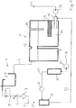
- FIG. 1 a fresh water connection of the shower toilet according to the exemplary embodiment is shown at 1 in the upper left.
- a fresh water supply line 2 the fresh water flows through a particle filter 3 and a control valve 4 as well as a switching valve 5 to a vertical separation section 6 prescribed for hygiene reasons.
- a vertical separation section 6 prescribed for hygiene reasons.
- From this line 7 leads to a water tank designated overall by 8. This is divided into two parts, namely a fresh water tank 9 for a water heater 10 on the left and a boiler 11 with an electric heater 12 on the right the line 7 can be filled.
- the boiler 11 has a heater 12 and a temperature sensor 19.
- a line 14 connects via a pump 31 an outlet of the fresh water tank 9 to the water heater 10, which has sensors for the water volume flow and the water temperature upstream and downstream of the water heater in the usual way. Downstream of the instantaneous water heater 10, a line 15 carries the water heated during operation through a particle filter 16 to a multi-way valve 17.
- the boiler 11 has an outlet arranged at the bottom, on which a T-piece is provided.
- a connection of the T-piece 18 leads via a pump 32 to the shower arm, not shown here, namely to the so-called boost nozzle 20.
- a connection of the valve 17 also leads to the shower arm, namely to the anal nozzle 21 arranged directly next to the boost nozzle 20 Valve 17 is connected via a return line 22 to a further connection of the T-piece 18.
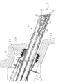
- FIG 2 shows a section through a distal end of a shower arm 24 in a bowl rim 23 of a shower toilet according to the invention.
- This shower toilet has a toilet bowl in the usual way, of which only the section of the bowl rim 23 can be seen.
- the bowl rim 23 there is an in Figure 2 recognizable channel-like opening, in and behind which a shower device is mounted.
- two spherical swirling chambers 25 are provided in the central region of the shower arm section, to which reference can be made to the prior art EP 2 628 546 , These bump into theirs Figure 2 a swirled water jet from the upper ends, which passes through the enlarged diameter nozzle openings 20 and 21 and thereby absorbs air from the environment within the shower arm.
- the two nozzles 20 and 21 are relatively closely adjacent and have a distance of approximately twice the diameter of the nozzle openings (on the upper shower arm surface).
- the nozzle 20 is referred to as the boost nozzle and the nozzle 21 as the anal nozzle; both are identical in terms of their geometry and are supplied via cables of the same cross-section. These lines are not shown here, but are located in front of and behind the cutting plane.
- a movable nozzle arm 26 can be seen under the two swirling chambers 25, which carries nozzle openings that are not numbered at its right (distal) end and can be extended to the vaginal shower on request.
- water is supplied via a channel 27, which extends and acts on the arm 26 against the force of a coil spring (not shown). This part of the shower device is not essential for the invention.
- channel 27 is a channel 28, which according to Figure 2 communicates with the ventilation of the nozzles 20 and 21.
- This channel 28 can also lead to washing water which exits via the nozzles 20 and 21 when the shower arm 24 (not shown) is completely retracted.
- a washing device 29 can be seen, which forms the distal end of the guide of the shower arm 24 and is held in the bowl rim 23.
- This washing device can be supplied with washing water via a channel 30 and can be used to clean the outer surface of the shower arm 24 when the shower arm 24 is extended and retracted.
- EP 2 626 478 For this, reference is made to the state of the art EP 2 626 478 ,
- the two nozzles 20 and 21 arranged on the top of the shower arm do not serve different anatomical purposes, but both (with the same structure, the same direction of radiation and in the immediate vicinity) for anal cleaning.
- a second nozzle opening is generally provided for vaginal cleaning, which in the present case can be carried out by the nozzle arm 26.
- the two nozzles 20 and 21 have the advantage of having the hot water supply system out Figure 1 To be able to be acted upon simultaneously, namely the boost nozzle 20 via the T-piece at the outlet of the boiler 11 and the anal nozzle 21 via the valve 17 and the water heater 10. However, they can also be operated individually without their individual Beam characteristics therefore changes.
- the shower toilet can recognize a user, for example by means of an infrared sensor, which causes the control to switch on the boiler 11, in particular its heater 12. This can also happen if the user is only near the shower toilet. If the start of toilet use is then detected, for example by a touch sensor, the controller can switch on the instantaneous water heater 10 and the pump in line 14 instead of the boiler 11 and adjust the valve 17 so that the heated water flows up to the nozzle line shower nozzle 21 rinses and drives out the cold water. This can be done before the shower arm 24 is extended so that the water emerging from the nozzle 21 fulfills a certain cleaning function with regard to the shower arm.
- the nozzle line between the boost nozzle 20 and the boiler 11 can be rinsed with hot water via the return line 22 (with the valve 17 in the appropriate position), again using the instantaneous water heater 10 the T-piece 18 z.
- a third of the volume flow of water can be passed into the boiler 11 in order to ensure improved mixing and in particular warming up of the cold zone in the vicinity of the outlet.
- the shower arm can be cleaned in the manner known per se when it is extended, for example again with water heated by the instantaneous water heater 10 and with the position of the valve 17 not explained in detail here, as a result of which the water reaches the washing device 29 via the connection 30.
- both nozzles 20 and 21 can be used, the valve 17 blocking the return line 22 and each nozzle being supplied by the boiler 11 or the instantaneous water heater 10 via its own nozzle line.
- the anal nozzle 21 can be operated with water heated by the water heater 10, so to speak, as an emergency program and the boost nozzle 20 only after a sufficient water temperature is available in the boiler 11.
- the exemplary embodiment shows that the separate line routing between the two nozzles and the associated water heaters 10 and 11 enables various advantages, which can be used in a flexible manner. If the return line 22 is present, this also applies to the flushing process described up to the boost nozzle 20 while protecting the energy content in the boiler 11.
- An electronic control is responsible for the functions shown so far, which is not shown in the figures, but is integrated in the shower toilet. According to the invention, this control has a descaling program in order to carry out automatic descaling. This is explained in more detail below.
- the water tank 8 is filled with a suitable decalcifying solution, which is then located both in the fresh water tank 9 and in the boiler 11.
- a technology assembly is descaled, namely in particular the continuous flow heater 10, the particle filter 16, the multi-way valve 17, the T-piece 18 and of course the fresh water tank 9 and the boiler 11 including heater 12 and temperature sensor 19.
- FIG 1 shown in line 14 and actually intended for the anal nozzle 21 pump 31 operated, the multi-way valve 17 switched so that the Lines 14 and 15 supplied decalcifying solution is continued via line 22, and the pump 32 assigned to the boost nozzle 20 (in Figure 1 blocked to the right of the T-piece 18).
- a circulation flow through the boiler, the instantaneous water heater and the return line 22 is thus generated here.
- the pump 31 can run for one minute and then pause for eight minutes. B. repeated three times.
- a second program step the anal nozzle 21 and the nozzle line leading to it are decalcified.
- the multi-way valve 17 is switched so that the decalcifying solution is expelled through the anal nozzle 21 and does not get into the return line 22.
- this program step further benefits the decalcification of the lines 14 and 15, the particle filter 16, the instantaneous water heater 10 and of course the pump 31.
- the corresponding parts of the multi-way valve 17 and the line sections leading downstream to the anal nozzle 21 and the anal nozzle 21 are descaled. So z. B. the existing in the fresh water tank 9 of decalcifying solution are used up, the inventory in the boiler is not touched.
- the boost nozzle 20 and the shower line leading to it, including the pump 32 can then be decalcified.
- this pump 32 is operated, draws decalcifying solution from the boiler 11 and expels it via the boost nozzle 20, for example for five seconds.
- the multi-way valve 17 is adjusted accordingly and decalcifying solution from the fresh water tank 9 via the pump 31 and the lines 14 and 15 is then in a Figure 1 supply line, not shown, and finally via channel 30 ( Figure 2 ) supplied to the washing device 29.
- the contents of the fresh water tank 9 can essentially be used up again here.
- the boost nozzle 20 can then be descaled again, as has already been described. Since there is still a descaling solution in the boiler 11 in this situation, a repetition is advisable.
- the descaling solution is redistributed in the system, but significantly diluted.
- the fresh water tank 9 can now be emptied first via the anal nozzle 21 and thus therefore via the lines 14 and 15 and the multi-way valve 17.
- the content of the boiler 11 can be emptied via the boost nozzle 20, that is to say via the T-piece 18 and the pump 32. Then, twelfth, both tanks, i.e. fresh water tank 9 and boiler 11, are refilled with water.
- the fresh water tank 9 can then be emptied again, but this time via the shower arm cleaning 29, ie again via lines 14 and 15 and the multi-way valve 17. Then, the boiler is emptied again fourteenthly, as already described per se. Fifteen, both tanks are freshly filled. Depending on the needs and aggressiveness of the original decalcifying solution, the rinsing steps can of course be repeated.
- the decalcification program is characterized by various circulation steps, which first improve the utilization of the decalcification solution, but also the thoroughness of the decalcification itself, but can subsequently also serve to distribute residual amounts of decalcification solution in the system.
- circulation steps flushing through both the boiler 11 and the instantaneous water heater 10 is possible.
- the nozzles 20 and 21, the shower lines assigned to them and also the shower arm cleaning 29 can be decalcified and rinsed in special descaling steps, then without circulation.
Landscapes
- Public Health (AREA)
- Health & Medical Sciences (AREA)
- Engineering & Computer Science (AREA)
- Hydrology & Water Resources (AREA)
- Life Sciences & Earth Sciences (AREA)
- Water Supply & Treatment (AREA)
- Molecular Biology (AREA)
- Epidemiology (AREA)
- Combustion & Propulsion (AREA)
- Mechanical Engineering (AREA)
- General Engineering & Computer Science (AREA)
- Chemical & Material Sciences (AREA)
- Physics & Mathematics (AREA)
- Thermal Sciences (AREA)
- Bidet-Like Cleaning Device And Other Flush Toilet Accessories (AREA)
Priority Applications (6)
| Application Number | Priority Date | Filing Date | Title |
|---|---|---|---|
| EP15020231.5A EP3170940B1 (de) | 2015-11-18 | 2015-11-18 | Dusch-wc mit einem wassererhitzer |
| ES15020231T ES2778101T3 (es) | 2015-11-18 | 2015-11-18 | Inodoro-bidé con calentador de agua |
| PL15020231T PL3170940T3 (pl) | 2015-11-18 | 2015-11-18 | WC z natryskiem z podgrzewaczem wody |
| PT150202315T PT3170940T (pt) | 2015-11-18 | 2015-11-18 | Sanita bidé com aquecedor de água |
| DK15020231.5T DK3170940T3 (da) | 2015-11-18 | 2015-11-18 | Brusetoilet med vandvarmer |
| CN201611272986.3A CN106988399B (zh) | 2015-11-18 | 2016-11-18 | 具有水加热器的冲洗座便器 |
Applications Claiming Priority (1)
| Application Number | Priority Date | Filing Date | Title |
|---|---|---|---|
| EP15020231.5A EP3170940B1 (de) | 2015-11-18 | 2015-11-18 | Dusch-wc mit einem wassererhitzer |
Publications (2)
| Publication Number | Publication Date |
|---|---|
| EP3170940A1 EP3170940A1 (de) | 2017-05-24 |
| EP3170940B1 true EP3170940B1 (de) | 2020-01-01 |
Family
ID=54608240
Family Applications (1)
| Application Number | Title | Priority Date | Filing Date |
|---|---|---|---|
| EP15020231.5A Active EP3170940B1 (de) | 2015-11-18 | 2015-11-18 | Dusch-wc mit einem wassererhitzer |
Country Status (6)
| Country | Link |
|---|---|
| EP (1) | EP3170940B1 (pl) |
| CN (1) | CN106988399B (pl) |
| DK (1) | DK3170940T3 (pl) |
| ES (1) | ES2778101T3 (pl) |
| PL (1) | PL3170940T3 (pl) |
| PT (1) | PT3170940T (pl) |
Families Citing this family (6)
| Publication number | Priority date | Publication date | Assignee | Title |
|---|---|---|---|---|
| JP6891697B2 (ja) * | 2017-07-25 | 2021-06-18 | Toto株式会社 | 衛生洗浄装置 |
| JP6369609B1 (ja) * | 2017-07-25 | 2018-08-08 | Toto株式会社 | 衛生洗浄装置 |
| JP6891698B2 (ja) * | 2017-07-25 | 2021-06-18 | Toto株式会社 | 衛生洗浄装置 |
| CN108331110B (zh) * | 2018-02-06 | 2024-08-16 | 浙江怡和卫浴有限公司 | 智能座便器 |
| CN110220307A (zh) * | 2018-03-02 | 2019-09-10 | 青岛经济技术开发区海尔热水器有限公司 | 一种除垢组件及燃气热水器 |
| CN110185110A (zh) * | 2019-06-13 | 2019-08-30 | 厦门帝恒诺卫浴科技有限公司 | 一种电子坐便器的水路清洁系统及其清洁方法 |
Citations (4)
| Publication number | Priority date | Publication date | Assignee | Title |
|---|---|---|---|---|
| WO2012051722A1 (de) | 2010-10-19 | 2012-04-26 | Presano Ag | Vorrichtung zum erwärmen von wasser für ein dusch-wc |
| EP2687641A1 (de) | 2012-07-20 | 2014-01-22 | Geberit International AG | Dusch-WC mit Wärmepumpe zum Erwärmen des Duschwassers |
| WO2015143571A1 (de) | 2014-03-25 | 2015-10-01 | Noventa Ag | Entkalkungskapsel für dusch-wc |
| EP3141668A1 (de) | 2015-09-09 | 2017-03-15 | Geberit International AG | Dusch-wc mit durchlauferhitzer und boiler |
Family Cites Families (11)
| Publication number | Priority date | Publication date | Assignee | Title |
|---|---|---|---|---|
| CN2183152Y (zh) * | 1994-02-04 | 1994-11-23 | 杨崇铭 | 多功能马桶座 |
| JP2000008451A (ja) * | 1998-06-19 | 2000-01-11 | Inax Corp | 温水タンク構造 |
| CN2383896Y (zh) * | 1999-02-04 | 2000-06-21 | 沈阳东大利德电子有限公司 | 电脑喷淋便座 |
| JP2001214501A (ja) * | 2000-01-31 | 2001-08-10 | Toray Ind Inc | 浄水器付き温水洗浄便座 |
| TWM266868U (en) * | 2004-11-29 | 2005-06-11 | Pei-Shiun Jau | Improved cleaning device structure |
| KR101544377B1 (ko) * | 2009-03-24 | 2015-08-13 | 코웨이 주식회사 | 살균수 생성장치 및 이를 구비하는 비데 |
| PL2357423T3 (pl) | 2009-12-24 | 2014-12-31 | Geberit Int Ag | Urządzenie do uzdatniania wody natryskowej dla ustępu spłukiwanego wodą, z natryskiem oddolnym i sposób eksploatacji takiego urządzenia |
| EP2484574B1 (en) * | 2011-02-07 | 2013-08-07 | ALSTOM Transport SA | A water storage and distribution system having a water tank by pass |
| EP2626478B1 (de) | 2012-02-07 | 2014-05-14 | Geberit International AG | Dusch-WC mit Reinigungseinrichtung für Duscharm |
| PT2628546E (pt) | 2012-02-16 | 2014-10-07 | Geberit Int Ag | Braço com chuveiro para sanita com jacto inferior |
| CN104532934B (zh) * | 2014-12-31 | 2016-08-17 | 浙江特洁尔智能洁具有限公司 | 一种智能坐便器的双管冲洗装置 |
-
2015
- 2015-11-18 PT PT150202315T patent/PT3170940T/pt unknown
- 2015-11-18 DK DK15020231.5T patent/DK3170940T3/da active
- 2015-11-18 ES ES15020231T patent/ES2778101T3/es active Active
- 2015-11-18 PL PL15020231T patent/PL3170940T3/pl unknown
- 2015-11-18 EP EP15020231.5A patent/EP3170940B1/de active Active
-
2016
- 2016-11-18 CN CN201611272986.3A patent/CN106988399B/zh active Active
Patent Citations (4)
| Publication number | Priority date | Publication date | Assignee | Title |
|---|---|---|---|---|
| WO2012051722A1 (de) | 2010-10-19 | 2012-04-26 | Presano Ag | Vorrichtung zum erwärmen von wasser für ein dusch-wc |
| EP2687641A1 (de) | 2012-07-20 | 2014-01-22 | Geberit International AG | Dusch-WC mit Wärmepumpe zum Erwärmen des Duschwassers |
| WO2015143571A1 (de) | 2014-03-25 | 2015-10-01 | Noventa Ag | Entkalkungskapsel für dusch-wc |
| EP3141668A1 (de) | 2015-09-09 | 2017-03-15 | Geberit International AG | Dusch-wc mit durchlauferhitzer und boiler |
Also Published As
| Publication number | Publication date |
|---|---|
| CN106988399B (zh) | 2022-07-19 |
| CN106988399A (zh) | 2017-07-28 |
| ES2778101T3 (es) | 2020-08-07 |
| PL3170940T3 (pl) | 2020-07-13 |
| EP3170940A1 (de) | 2017-05-24 |
| DK3170940T3 (da) | 2020-03-23 |
| PT3170940T (pt) | 2020-03-24 |
Similar Documents
| Publication | Publication Date | Title |
|---|---|---|
| EP3170940B1 (de) | Dusch-wc mit einem wassererhitzer | |
| EP3337931B1 (de) | Vorrichtung und verfahren zum selbsttätigen spülen mit mehrfachventil | |
| WO2007098732A2 (de) | Verfahren zur reinigung eines gargerätes und gargerät | |
| EP2842474B1 (de) | Wasserführendes Haushaltsgerät mit einer Heizeinrichtung | |
| EP1717518A1 (de) | Gargerät mit einem Garraumablauf und einem Siphon | |
| EP3141668B1 (de) | Dusch-wc mit durchlauferhitzer und boiler | |
| DE102008039160A1 (de) | Reinigungs- und Desinfektionsgerät mit verstellbarer Düse | |
| EP2125641B1 (de) | Warmwassergerät | |
| EP2626478B1 (de) | Dusch-WC mit Reinigungseinrichtung für Duscharm | |
| EP3085841A1 (de) | Intimdusche mit uv-reinigungseinrichtung | |
| DE102011077083A1 (de) | Geschirrspülmaschine, insbesondere Haushaltsgeschirrspülmaschine | |
| DE102014112756A1 (de) | Verfahren zur Reinigung eines Milch führenden Strömungsleitungssystems eines Getränkeautomaten und Getränkeautomat zur Durchführung des Verfahrens | |
| EP2687641B1 (de) | Dusch-WC mit Wärmepumpe zum Erwärmen des Duschwassers | |
| DE102009054161B4 (de) | Vorrichtung zum Reinigen und Desinfizieren von Reinigungsgut und Verfahren zur Desinfektion einer Vorrichtung der vorgenannten Art | |
| DE102011108884A1 (de) | System zur Leitungsbehandlung | |
| EP3599421B1 (de) | Reinigungssystem für die reinigung des garraums eines gargeräts | |
| DE102006061082A1 (de) | Wasserführendes Haushaltsgerät mit einer Zugabevorrichtung für Reinigungsmittel | |
| DE202015007909U1 (de) | Dusch-WC mit einem Wassererhitzer | |
| EP3366849B1 (de) | Haushaltsgerät zur ausgabe von flüssigkeit mit einer ablassleitung | |
| DE102020124483B4 (de) | Reinigungs- und Desinfektionsautomat und Verfahren zum Betreiben eines Reinigungs- und Desinfektionsautomaten | |
| WO2015197348A1 (de) | Fahrzeug mit bidet | |
| DE102015114469B3 (de) | System zur Führung von Kaltwasser, Verfahren zur Kühlung einer Kaltwasserstrecke und Verwendung einer Leitung zur Führung von Kaltwasser | |
| DE102017108349A1 (de) | Wasch- oder Spülmaschine mit einer Heizeinrichtung zur Aufheizung der Wasch- oder Spülflüssigkeit | |
| DE202015006214U1 (de) | Dusch-WC mit Durchlauferhitzer und Boiler | |
| DE102009042866B4 (de) | Geschirrspülmaschine und Verfahren zum Spülen von Geschirr |
Legal Events
| Date | Code | Title | Description |
|---|---|---|---|
| PUAI | Public reference made under article 153(3) epc to a published international application that has entered the european phase |
Free format text: ORIGINAL CODE: 0009012 |
|
| STAA | Information on the status of an ep patent application or granted ep patent |
Free format text: STATUS: REQUEST FOR EXAMINATION WAS MADE |
|
| 17P | Request for examination filed |
Effective date: 20161223 |
|
| AK | Designated contracting states |
Kind code of ref document: A1 Designated state(s): AL AT BE BG CH CY CZ DE DK EE ES FI FR GB GR HR HU IE IS IT LI LT LU LV MC MK MT NL NO PL PT RO RS SE SI SK SM TR |
|
| AX | Request for extension of the european patent |
Extension state: BA ME |
|
| RBV | Designated contracting states (corrected) |
Designated state(s): AL AT BE BG CH CY CZ DE DK EE ES FI FR GB GR HR HU IE IS IT LI LT LU LV MC MK MT NL NO PL PT RO RS SE SI SK SM TR |
|
| GRAP | Despatch of communication of intention to grant a patent |
Free format text: ORIGINAL CODE: EPIDOSNIGR1 |
|
| STAA | Information on the status of an ep patent application or granted ep patent |
Free format text: STATUS: GRANT OF PATENT IS INTENDED |
|
| INTG | Intention to grant announced |
Effective date: 20190703 |
|
| GRAS | Grant fee paid |
Free format text: ORIGINAL CODE: EPIDOSNIGR3 |
|
| GRAA | (expected) grant |
Free format text: ORIGINAL CODE: 0009210 |
|
| STAA | Information on the status of an ep patent application or granted ep patent |
Free format text: STATUS: THE PATENT HAS BEEN GRANTED |
|
| AK | Designated contracting states |
Kind code of ref document: B1 Designated state(s): AL AT BE BG CH CY CZ DE DK EE ES FI FR GB GR HR HU IE IS IT LI LT LU LV MC MK MT NL NO PL PT RO RS SE SI SK SM TR |
|
| REG | Reference to a national code |
Ref country code: GB Ref legal event code: FG4D Free format text: NOT ENGLISH |
|
| REG | Reference to a national code |
Ref country code: CH Ref legal event code: EP Ref country code: AT Ref legal event code: REF Ref document number: 1219927 Country of ref document: AT Kind code of ref document: T Effective date: 20200115 |
|
| REG | Reference to a national code |
Ref country code: IE Ref legal event code: FG4D Free format text: LANGUAGE OF EP DOCUMENT: GERMAN |
|
| REG | Reference to a national code |
Ref country code: DE Ref legal event code: R096 Ref document number: 502015011354 Country of ref document: DE |
|
| REG | Reference to a national code |
Ref country code: DE Ref legal event code: R026 Ref document number: 502015011354 Country of ref document: DE |
|
| PLBI | Opposition filed |
Free format text: ORIGINAL CODE: 0009260 |
|
| REG | Reference to a national code |
Ref country code: CH Ref legal event code: NV Representative=s name: TR-IP CONSULTING LLC, CH |
|
| REG | Reference to a national code |
Ref country code: NO Ref legal event code: T2 Effective date: 20200101 Ref country code: DK Ref legal event code: T3 Effective date: 20200318 |
|
| REG | Reference to a national code |
Ref country code: PT Ref legal event code: SC4A Ref document number: 3170940 Country of ref document: PT Date of ref document: 20200324 Kind code of ref document: T Free format text: AVAILABILITY OF NATIONAL TRANSLATION Effective date: 20200310 Ref country code: FI Ref legal event code: MDE Opponent name: PRESANO AG |
|
| 26 | Opposition filed |
Opponent name: PRESANO AG Effective date: 20200217 |
|
| REG | Reference to a national code |
Ref country code: NL Ref legal event code: FP |
|
| REG | Reference to a national code |
Ref country code: LT Ref legal event code: MG4D |
|
| PG25 | Lapsed in a contracting state [announced via postgrant information from national office to epo] |
Ref country code: RS Free format text: LAPSE BECAUSE OF FAILURE TO SUBMIT A TRANSLATION OF THE DESCRIPTION OR TO PAY THE FEE WITHIN THE PRESCRIBED TIME-LIMIT Effective date: 20200101 Ref country code: FI Free format text: LAPSE BECAUSE OF FAILURE TO SUBMIT A TRANSLATION OF THE DESCRIPTION OR TO PAY THE FEE WITHIN THE PRESCRIBED TIME-LIMIT Effective date: 20200101 Ref country code: CZ Free format text: LAPSE BECAUSE OF FAILURE TO SUBMIT A TRANSLATION OF THE DESCRIPTION OR TO PAY THE FEE WITHIN THE PRESCRIBED TIME-LIMIT Effective date: 20200101 Ref country code: LT Free format text: LAPSE BECAUSE OF FAILURE TO SUBMIT A TRANSLATION OF THE DESCRIPTION OR TO PAY THE FEE WITHIN THE PRESCRIBED TIME-LIMIT Effective date: 20200101 |
|
| REG | Reference to a national code |
Ref country code: ES Ref legal event code: FG2A Ref document number: 2778101 Country of ref document: ES Kind code of ref document: T3 Effective date: 20200807 |
|
| PG25 | Lapsed in a contracting state [announced via postgrant information from national office to epo] |
Ref country code: IS Free format text: LAPSE BECAUSE OF FAILURE TO SUBMIT A TRANSLATION OF THE DESCRIPTION OR TO PAY THE FEE WITHIN THE PRESCRIBED TIME-LIMIT Effective date: 20200501 Ref country code: BG Free format text: LAPSE BECAUSE OF FAILURE TO SUBMIT A TRANSLATION OF THE DESCRIPTION OR TO PAY THE FEE WITHIN THE PRESCRIBED TIME-LIMIT Effective date: 20200401 Ref country code: HR Free format text: LAPSE BECAUSE OF FAILURE TO SUBMIT A TRANSLATION OF THE DESCRIPTION OR TO PAY THE FEE WITHIN THE PRESCRIBED TIME-LIMIT Effective date: 20200101 Ref country code: GR Free format text: LAPSE BECAUSE OF FAILURE TO SUBMIT A TRANSLATION OF THE DESCRIPTION OR TO PAY THE FEE WITHIN THE PRESCRIBED TIME-LIMIT Effective date: 20200402 Ref country code: SE Free format text: LAPSE BECAUSE OF FAILURE TO SUBMIT A TRANSLATION OF THE DESCRIPTION OR TO PAY THE FEE WITHIN THE PRESCRIBED TIME-LIMIT Effective date: 20200101 Ref country code: LV Free format text: LAPSE BECAUSE OF FAILURE TO SUBMIT A TRANSLATION OF THE DESCRIPTION OR TO PAY THE FEE WITHIN THE PRESCRIBED TIME-LIMIT Effective date: 20200101 |
|
| PLAX | Notice of opposition and request to file observation + time limit sent |
Free format text: ORIGINAL CODE: EPIDOSNOBS2 |
|
| PG25 | Lapsed in a contracting state [announced via postgrant information from national office to epo] |
Ref country code: EE Free format text: LAPSE BECAUSE OF FAILURE TO SUBMIT A TRANSLATION OF THE DESCRIPTION OR TO PAY THE FEE WITHIN THE PRESCRIBED TIME-LIMIT Effective date: 20200101 Ref country code: SM Free format text: LAPSE BECAUSE OF FAILURE TO SUBMIT A TRANSLATION OF THE DESCRIPTION OR TO PAY THE FEE WITHIN THE PRESCRIBED TIME-LIMIT Effective date: 20200101 Ref country code: SK Free format text: LAPSE BECAUSE OF FAILURE TO SUBMIT A TRANSLATION OF THE DESCRIPTION OR TO PAY THE FEE WITHIN THE PRESCRIBED TIME-LIMIT Effective date: 20200101 Ref country code: RO Free format text: LAPSE BECAUSE OF FAILURE TO SUBMIT A TRANSLATION OF THE DESCRIPTION OR TO PAY THE FEE WITHIN THE PRESCRIBED TIME-LIMIT Effective date: 20200101 |
|
| PLBB | Reply of patent proprietor to notice(s) of opposition received |
Free format text: ORIGINAL CODE: EPIDOSNOBS3 |
|
| PG25 | Lapsed in a contracting state [announced via postgrant information from national office to epo] |
Ref country code: SI Free format text: LAPSE BECAUSE OF FAILURE TO SUBMIT A TRANSLATION OF THE DESCRIPTION OR TO PAY THE FEE WITHIN THE PRESCRIBED TIME-LIMIT Effective date: 20200101 |
|
| PG25 | Lapsed in a contracting state [announced via postgrant information from national office to epo] |
Ref country code: MC Free format text: LAPSE BECAUSE OF FAILURE TO SUBMIT A TRANSLATION OF THE DESCRIPTION OR TO PAY THE FEE WITHIN THE PRESCRIBED TIME-LIMIT Effective date: 20200101 |
|
| PLCK | Communication despatched that opposition was rejected |
Free format text: ORIGINAL CODE: EPIDOSNREJ1 |
|
| APBM | Appeal reference recorded |
Free format text: ORIGINAL CODE: EPIDOSNREFNO |
|
| APBP | Date of receipt of notice of appeal recorded |
Free format text: ORIGINAL CODE: EPIDOSNNOA2O |
|
| APAH | Appeal reference modified |
Free format text: ORIGINAL CODE: EPIDOSCREFNO |
|
| APBQ | Date of receipt of statement of grounds of appeal recorded |
Free format text: ORIGINAL CODE: EPIDOSNNOA3O |
|
| PG25 | Lapsed in a contracting state [announced via postgrant information from national office to epo] |
Ref country code: MT Free format text: LAPSE BECAUSE OF FAILURE TO SUBMIT A TRANSLATION OF THE DESCRIPTION OR TO PAY THE FEE WITHIN THE PRESCRIBED TIME-LIMIT Effective date: 20200101 Ref country code: CY Free format text: LAPSE BECAUSE OF FAILURE TO SUBMIT A TRANSLATION OF THE DESCRIPTION OR TO PAY THE FEE WITHIN THE PRESCRIBED TIME-LIMIT Effective date: 20200101 |
|
| PG25 | Lapsed in a contracting state [announced via postgrant information from national office to epo] |
Ref country code: MK Free format text: LAPSE BECAUSE OF FAILURE TO SUBMIT A TRANSLATION OF THE DESCRIPTION OR TO PAY THE FEE WITHIN THE PRESCRIBED TIME-LIMIT Effective date: 20200101 Ref country code: AL Free format text: LAPSE BECAUSE OF FAILURE TO SUBMIT A TRANSLATION OF THE DESCRIPTION OR TO PAY THE FEE WITHIN THE PRESCRIBED TIME-LIMIT Effective date: 20200101 |
|
| P01 | Opt-out of the competence of the unified patent court (upc) registered |
Effective date: 20230507 |
|
| REG | Reference to a national code |
Ref country code: NL Ref legal event code: PD Owner name: GEBERIT HOLDING AG; CH Free format text: DETAILS ASSIGNMENT: CHANGE OF OWNER(S), MERGE; FORMER OWNER NAME: GEBERIT INTERNATIONAL AG Effective date: 20240604 Ref country code: NL Ref legal event code: HC Owner name: GEBERIT INTERNATIONAL AG; CH Free format text: DETAILS ASSIGNMENT: CHANGE OF OWNER(S), CHANGE OF OWNER(S) NAME; FORMER OWNER NAME: GEBERIT HOLDING AG Effective date: 20240604 |
|
| REG | Reference to a national code |
Ref country code: BE Ref legal event code: PD Owner name: GEBERIT HOLDING AG; CH Free format text: DETAILS ASSIGNMENT: CHANGE OF OWNER(S), MERGE; FORMER OWNER NAME: GEBERIT INTERNATIONAL AG Effective date: 20240528 Ref country code: BE Ref legal event code: HC Owner name: GEBERIT INTERNATIONAL AG; CH Free format text: DETAILS ASSIGNMENT: CHANGE OF OWNER(S), CHANGE OF OWNER(S) NAME; FORMER OWNER NAME: GEBERIT HOLDING AG Effective date: 20240528 |
|
| REG | Reference to a national code |
Ref country code: DE Ref legal event code: R100 Ref document number: 502015011354 Country of ref document: DE |
|
| APBU | Appeal procedure closed |
Free format text: ORIGINAL CODE: EPIDOSNNOA9O |
|
| PLBN | Opposition rejected |
Free format text: ORIGINAL CODE: 0009273 |
|
| STAA | Information on the status of an ep patent application or granted ep patent |
Free format text: STATUS: OPPOSITION REJECTED |
|
| 27O | Opposition rejected |
Effective date: 20240924 |
|
| REG | Reference to a national code |
Ref country code: AT Ref legal event code: PC Ref document number: 1219927 Country of ref document: AT Kind code of ref document: T Owner name: GEBERIT INTERNATIONAL AG, CH Effective date: 20241118 |
|
| REG | Reference to a national code |
Ref country code: DE Ref legal event code: R082 Ref document number: 502015011354 Country of ref document: DE Representative=s name: SZYNKA SMORODIN PATENTANWAELTE PARTNERSCHAFT M, DE |
|
| REG | Reference to a national code |
Ref country code: CH Ref legal event code: R17 Free format text: ST27 STATUS EVENT CODE: U-0-0-R10-R17 (AS PROVIDED BY THE NATIONAL OFFICE) Effective date: 20251024 |
|
| REG | Reference to a national code |
Ref country code: CH Ref legal event code: U11 Free format text: ST27 STATUS EVENT CODE: U-0-0-U10-U11 (AS PROVIDED BY THE NATIONAL OFFICE) Effective date: 20251201 |
|
| PGFP | Annual fee paid to national office [announced via postgrant information from national office to epo] |
Ref country code: PT Payment date: 20251105 Year of fee payment: 11 |
|
| PGFP | Annual fee paid to national office [announced via postgrant information from national office to epo] |
Ref country code: LU Payment date: 20251118 Year of fee payment: 11 Ref country code: NL Payment date: 20251119 Year of fee payment: 11 |
|
| PGFP | Annual fee paid to national office [announced via postgrant information from national office to epo] |
Ref country code: DE Payment date: 20251118 Year of fee payment: 11 |
|
| PGFP | Annual fee paid to national office [announced via postgrant information from national office to epo] |
Ref country code: GB Payment date: 20251120 Year of fee payment: 11 |
|
| PGFP | Annual fee paid to national office [announced via postgrant information from national office to epo] |
Ref country code: NO Payment date: 20251118 Year of fee payment: 11 |
|
| PGFP | Annual fee paid to national office [announced via postgrant information from national office to epo] |
Ref country code: AT Payment date: 20251117 Year of fee payment: 11 |
|
| PGFP | Annual fee paid to national office [announced via postgrant information from national office to epo] |
Ref country code: IT Payment date: 20251128 Year of fee payment: 11 Ref country code: DK Payment date: 20251119 Year of fee payment: 11 |
|
| PGFP | Annual fee paid to national office [announced via postgrant information from national office to epo] |
Ref country code: FR Payment date: 20251120 Year of fee payment: 11 |
|
| PGFP | Annual fee paid to national office [announced via postgrant information from national office to epo] |
Ref country code: BE Payment date: 20251118 Year of fee payment: 11 Ref country code: TR Payment date: 20251113 Year of fee payment: 11 |
|
| PGFP | Annual fee paid to national office [announced via postgrant information from national office to epo] |
Ref country code: CH Payment date: 20251201 Year of fee payment: 11 |
|
| PGFP | Annual fee paid to national office [announced via postgrant information from national office to epo] |
Ref country code: IE Payment date: 20251120 Year of fee payment: 11 |
|
| PGFP | Annual fee paid to national office [announced via postgrant information from national office to epo] |
Ref country code: PL Payment date: 20251110 Year of fee payment: 11 |
|
| PGFP | Annual fee paid to national office [announced via postgrant information from national office to epo] |
Ref country code: ES Payment date: 20251216 Year of fee payment: 11 |