EP3170656B1 - Tank-innenrohrleitung und tank mit zumindest einer tank-innenrohrleitung - Google Patents
Tank-innenrohrleitung und tank mit zumindest einer tank-innenrohrleitung Download PDFInfo
- Publication number
- EP3170656B1 EP3170656B1 EP15195886.5A EP15195886A EP3170656B1 EP 3170656 B1 EP3170656 B1 EP 3170656B1 EP 15195886 A EP15195886 A EP 15195886A EP 3170656 B1 EP3170656 B1 EP 3170656B1
- Authority
- EP
- European Patent Office
- Prior art keywords
- tank
- layer
- inner pipe
- intermediate layer
- pipe
- Prior art date
- Legal status (The legal status is an assumption and is not a legal conclusion. Google has not performed a legal analysis and makes no representation as to the accuracy of the status listed.)
- Active
Links
Images

Classifications
-
- B—PERFORMING OPERATIONS; TRANSPORTING
- B32—LAYERED PRODUCTS
- B32B—LAYERED PRODUCTS, i.e. PRODUCTS BUILT-UP OF STRATA OF FLAT OR NON-FLAT, e.g. CELLULAR OR HONEYCOMB, FORM
- B32B1/00—Layered products having a non-planar shape
- B32B1/08—Tubular products
-
- B—PERFORMING OPERATIONS; TRANSPORTING
- B32—LAYERED PRODUCTS
- B32B—LAYERED PRODUCTS, i.e. PRODUCTS BUILT-UP OF STRATA OF FLAT OR NON-FLAT, e.g. CELLULAR OR HONEYCOMB, FORM
- B32B27/00—Layered products comprising a layer of synthetic resin
- B32B27/06—Layered products comprising a layer of synthetic resin as the main or only constituent of a layer, which is next to another layer of the same or of a different material
- B32B27/08—Layered products comprising a layer of synthetic resin as the main or only constituent of a layer, which is next to another layer of the same or of a different material of synthetic resin
-
- B—PERFORMING OPERATIONS; TRANSPORTING
- B32—LAYERED PRODUCTS
- B32B—LAYERED PRODUCTS, i.e. PRODUCTS BUILT-UP OF STRATA OF FLAT OR NON-FLAT, e.g. CELLULAR OR HONEYCOMB, FORM
- B32B27/00—Layered products comprising a layer of synthetic resin
- B32B27/18—Layered products comprising a layer of synthetic resin characterised by the use of special additives
-
- B—PERFORMING OPERATIONS; TRANSPORTING
- B32—LAYERED PRODUCTS
- B32B—LAYERED PRODUCTS, i.e. PRODUCTS BUILT-UP OF STRATA OF FLAT OR NON-FLAT, e.g. CELLULAR OR HONEYCOMB, FORM
- B32B27/00—Layered products comprising a layer of synthetic resin
- B32B27/34—Layered products comprising a layer of synthetic resin comprising polyamides
-
- B—PERFORMING OPERATIONS; TRANSPORTING
- B32—LAYERED PRODUCTS
- B32B—LAYERED PRODUCTS, i.e. PRODUCTS BUILT-UP OF STRATA OF FLAT OR NON-FLAT, e.g. CELLULAR OR HONEYCOMB, FORM
- B32B3/00—Layered products comprising a layer with external or internal discontinuities or unevennesses, or a layer of non-planar shape; Layered products comprising a layer having particular features of form
- B32B3/26—Layered products comprising a layer with external or internal discontinuities or unevennesses, or a layer of non-planar shape; Layered products comprising a layer having particular features of form characterised by a particular shape of the outline of the cross-section of a continuous layer; characterised by a layer with cavities or internal voids ; characterised by an apertured layer
- B32B3/28—Layered products comprising a layer with external or internal discontinuities or unevennesses, or a layer of non-planar shape; Layered products comprising a layer having particular features of form characterised by a particular shape of the outline of the cross-section of a continuous layer; characterised by a layer with cavities or internal voids ; characterised by an apertured layer characterised by a layer comprising a deformed thin sheet, i.e. the layer having its entire thickness deformed out of the plane, e.g. corrugated, crumpled
-
- B—PERFORMING OPERATIONS; TRANSPORTING
- B32—LAYERED PRODUCTS
- B32B—LAYERED PRODUCTS, i.e. PRODUCTS BUILT-UP OF STRATA OF FLAT OR NON-FLAT, e.g. CELLULAR OR HONEYCOMB, FORM
- B32B3/00—Layered products comprising a layer with external or internal discontinuities or unevennesses, or a layer of non-planar shape; Layered products comprising a layer having particular features of form
- B32B3/26—Layered products comprising a layer with external or internal discontinuities or unevennesses, or a layer of non-planar shape; Layered products comprising a layer having particular features of form characterised by a particular shape of the outline of the cross-section of a continuous layer; characterised by a layer with cavities or internal voids ; characterised by an apertured layer
- B32B3/30—Layered products comprising a layer with external or internal discontinuities or unevennesses, or a layer of non-planar shape; Layered products comprising a layer having particular features of form characterised by a particular shape of the outline of the cross-section of a continuous layer; characterised by a layer with cavities or internal voids ; characterised by an apertured layer characterised by a layer formed with recesses or projections, e.g. hollows, grooves, protuberances, ribs
-
- B—PERFORMING OPERATIONS; TRANSPORTING
- B32—LAYERED PRODUCTS
- B32B—LAYERED PRODUCTS, i.e. PRODUCTS BUILT-UP OF STRATA OF FLAT OR NON-FLAT, e.g. CELLULAR OR HONEYCOMB, FORM
- B32B7/00—Layered products characterised by the relation between layers; Layered products characterised by the relative orientation of features between layers, or by the relative values of a measurable parameter between layers, i.e. products comprising layers having different physical, chemical or physicochemical properties; Layered products characterised by the interconnection of layers
- B32B7/04—Interconnection of layers
- B32B7/12—Interconnection of layers using interposed adhesives or interposed materials with bonding properties
-
- B—PERFORMING OPERATIONS; TRANSPORTING
- B60—VEHICLES IN GENERAL
- B60K—ARRANGEMENT OR MOUNTING OF PROPULSION UNITS OR OF TRANSMISSIONS IN VEHICLES; ARRANGEMENT OR MOUNTING OF PLURAL DIVERSE PRIME-MOVERS IN VEHICLES; AUXILIARY DRIVES FOR VEHICLES; INSTRUMENTATION OR DASHBOARDS FOR VEHICLES; ARRANGEMENTS IN CONNECTION WITH COOLING, AIR INTAKE, GAS EXHAUST OR FUEL SUPPLY OF PROPULSION UNITS IN VEHICLES
- B60K15/00—Arrangement in connection with fuel supply of combustion engines or other fuel consuming energy converters, e.g. fuel cells; Mounting or construction of fuel tanks
- B60K15/01—Arrangement of fuel conduits
-
- B—PERFORMING OPERATIONS; TRANSPORTING
- B32—LAYERED PRODUCTS
- B32B—LAYERED PRODUCTS, i.e. PRODUCTS BUILT-UP OF STRATA OF FLAT OR NON-FLAT, e.g. CELLULAR OR HONEYCOMB, FORM
- B32B2250/00—Layers arrangement
- B32B2250/03—3 layers
-
- B—PERFORMING OPERATIONS; TRANSPORTING
- B32—LAYERED PRODUCTS
- B32B—LAYERED PRODUCTS, i.e. PRODUCTS BUILT-UP OF STRATA OF FLAT OR NON-FLAT, e.g. CELLULAR OR HONEYCOMB, FORM
- B32B2250/00—Layers arrangement
- B32B2250/24—All layers being polymeric
-
- B—PERFORMING OPERATIONS; TRANSPORTING
- B32—LAYERED PRODUCTS
- B32B—LAYERED PRODUCTS, i.e. PRODUCTS BUILT-UP OF STRATA OF FLAT OR NON-FLAT, e.g. CELLULAR OR HONEYCOMB, FORM
- B32B2307/00—Properties of the layers or laminate
- B32B2307/20—Properties of the layers or laminate having particular electrical or magnetic properties, e.g. piezoelectric
- B32B2307/202—Conductive
-
- B—PERFORMING OPERATIONS; TRANSPORTING
- B32—LAYERED PRODUCTS
- B32B—LAYERED PRODUCTS, i.e. PRODUCTS BUILT-UP OF STRATA OF FLAT OR NON-FLAT, e.g. CELLULAR OR HONEYCOMB, FORM
- B32B2307/00—Properties of the layers or laminate
- B32B2307/70—Other properties
- B32B2307/718—Weight, e.g. weight per square meter
-
- B—PERFORMING OPERATIONS; TRANSPORTING
- B32—LAYERED PRODUCTS
- B32B—LAYERED PRODUCTS, i.e. PRODUCTS BUILT-UP OF STRATA OF FLAT OR NON-FLAT, e.g. CELLULAR OR HONEYCOMB, FORM
- B32B2307/00—Properties of the layers or laminate
- B32B2307/70—Other properties
- B32B2307/732—Dimensional properties
-
- B—PERFORMING OPERATIONS; TRANSPORTING
- B32—LAYERED PRODUCTS
- B32B—LAYERED PRODUCTS, i.e. PRODUCTS BUILT-UP OF STRATA OF FLAT OR NON-FLAT, e.g. CELLULAR OR HONEYCOMB, FORM
- B32B2309/00—Parameters for the laminating or treatment process; Apparatus details
- B32B2309/08—Dimensions, e.g. volume
- B32B2309/10—Dimensions, e.g. volume linear, e.g. length, distance, width
- B32B2309/105—Thickness
-
- B—PERFORMING OPERATIONS; TRANSPORTING
- B32—LAYERED PRODUCTS
- B32B—LAYERED PRODUCTS, i.e. PRODUCTS BUILT-UP OF STRATA OF FLAT OR NON-FLAT, e.g. CELLULAR OR HONEYCOMB, FORM
- B32B2439/00—Containers; Receptacles
- B32B2439/40—Closed containers
-
- B—PERFORMING OPERATIONS; TRANSPORTING
- B32—LAYERED PRODUCTS
- B32B—LAYERED PRODUCTS, i.e. PRODUCTS BUILT-UP OF STRATA OF FLAT OR NON-FLAT, e.g. CELLULAR OR HONEYCOMB, FORM
- B32B2597/00—Tubular articles, e.g. hoses, pipes
-
- B—PERFORMING OPERATIONS; TRANSPORTING
- B32—LAYERED PRODUCTS
- B32B—LAYERED PRODUCTS, i.e. PRODUCTS BUILT-UP OF STRATA OF FLAT OR NON-FLAT, e.g. CELLULAR OR HONEYCOMB, FORM
- B32B2605/00—Vehicles
Definitions
- the invention relates to a tank inner pipe, in particular in fuel tanks of motor vehicles, wherein the pipe has a fluid channel surrounded by a pipe wall.
- the invention further relates to a tank with at least one such tank inner pipe.
- Tank inner pipeline means in the context of the invention that the pipeline according to the invention is arranged in the interior of a tank or runs through the interior of a tank. This is in particular a tank inner pipe, which runs through the interior of a fuel tank of a motor vehicle.
- the invention mainly relates to a motor vehicle tank inner pipe.
- the US 2007/134458 A1 discloses a tubing, the tubing having a fluid channel surrounded by a tube wall, the tubing wall being at least three layers, wherein an aromatic polyamide based outer layer is provided with an intermediate layer, and wherein an aromatic polyamide based inner layer is provided is.
- the invention is therefore based on the technical problem of specifying a tank inner pipe of the type mentioned, which is characterized by a high temperature resistance, in particular up to temperatures of at least 120 °, the wall material is resistant to unwanted washouts and the rest is simple and inexpensive to build or manufacturable.
- the invention is further based on the technical problem of specifying a tank with at least one such tank inner pipe.
- the invention teaches a tank according to claim 1. It is within the scope of the invention that the outer layer of at least 80 wt .-%, preferably from at least 85 wt .-%, preferably from at least 90 wt .-% and most preferably at least 95% by weight of an aromatic polyamide and recommended polyphthalamide (PPA). According to a very proven embodiment, the outer layer consists of at least 97 wt .-%, preferably at least 98 wt .-% of the aromatic Polyamides, recommended in polyphthalamide (PPA).
- the outer layer has a layer thickness of 0.1 mm to 1.3 mm, preferably from 0.2 mm to 1.2 mm, preferably from 0.2 mm to 1 mm and very preferably from 0.25 mm up to 0.9 mm.
- the outer layer is formed electrically conductive.
- the outer layer expediently suitable conductivity additives - such as soot or the like - on.
- the intermediate layer consists of at least 80% by weight, preferably of at least 85% by weight, preferably of at least 90% by weight and very preferably of at least 95% by weight of a polyamide and preferably of an aliphatic polyamide , According to a very preferred embodiment of the invention, the intermediate layer consists of at least 97% by weight and preferably of at least 98% by weight of the polyamide, preferably of the aliphatic polyamide.
- a particularly proven embodiment of the invention is characterized in that the intermediate layer is formed on the basis of polyamide 6. According to another embodiment, the intermediate layer is based on polyamide 12 and / or of polyamide 6.6.
- the intermediate layer has a layer thickness of from 0.1 to 1.3 mm, preferably from 0.2 to 1.2 mm, preferably from 0.2 mm to 1 mm and very preferably from 0.25 mm to 0 , 9 mm.
- the intermediate layer can also be designed to be electrically conductive.
- PPA polyphthalamide
- the inner layer is at least 97% by weight and preferably at least 98% by weight of the aromatic polyamide and recommended polyphthalamide (PPA).
- the inner layer of the pipeline has a layer thickness of from 0.1 mm to 1.3 mm, preferably from 0.2 mm to 1.2 mm, preferably from 0.2 mm to 1 mm and particularly preferably from 0, 25 mm to 0.9 mm.
- the outer layer is electrically conductive.
- the outer layer is expediently provided with suitable conductivity additives - for example with carbon black or the like.
- a preferred embodiment of the invention is characterized in that the intermediate layer has a higher layer thickness than the outer layer and / or the inner layer.
- the intermediate layer is formed as the thickest layer of the pipe wall of the tank inner pipe according to the invention.
- the intermediate layer is 1.1 to 2.5 times and preferably 1.2 to 2 times, and more preferably 1.2 to 1.8 times as thick as the outer layer and / or the inner layer.
- both the outer layer and the inner layer is arranged electrically conductive.
- the intermediate layer can also be designed to be electrically conductive.
- a particularly recommended embodiment of the invention is characterized in that the tank inner pipe according to the invention has only the three layers with outer layer, intermediate layer and inner layer.
- the tank internal pipeline according to the invention can still have further layers.
- the outer layer can be connected to the intermediate layer via an adhesive layer, which adhesive layer improves the adhesion between the outer layer and the intermediate layer.
- the intermediate layer with the Inner layer may be connected via an adhesive layer, which adhesive layer improves the adhesion between the inner layer and the intermediate layer. It is also within the scope of the invention that between the outer layer and the inner layer at least one barrier layer with barrier properties with respect to the fuel passed through the pipeline or with respect to a component of this fuel is arranged.
- the tank inner pipe is connected to a pump arranged in the associated tank, in particular in the associated fuel tank of the motor vehicle.
- the pump By means of the pump, the fluid medium present in the tank or the fuel arranged in the fuel tank is conveyed through the tank inner pipeline.
- the tank inner pipe according to the invention can also serve for pressure equalization and / or for leveling between different areas of the tank or fuel tank.
- the tank internal pipe according to the invention is arranged in the interior or in the interior of a tank or fuel tank.
- a particularly preferred embodiment of the invention is characterized in that the tank inner pipe according to the invention is at least partially - preferably completely - designed in the form of a corrugated pipe. It is within the scope of the invention that the wave crests and wave troughs of the pipeline run around the circumference of the pipeline. Expediently, the wave crests and the wave troughs of the pipeline have equal / constant distances from each other or substantially equal / constant distances from one another over at least part of the length of the pipeline, preferably over the entire length or essentially over the entire length of the pipeline.
- the embodiment as a corrugated tube has proven particularly useful in the context of the invention. This embodiment has According to one embodiment of the tank while the tank inner pipe is at least partially disposed on the wall of the tank or fuel tank. In principle, however, the tank inner pipe can also run through other areas of the tank or fuel tank.
- the invention is based on the finding that the tank inner pipe according to the invention is characterized by an excellent temperature resistance and also by an optimal mechanical resistance.
- the pipes according to the invention are stable at temperatures of -40 ° C up to 120 ° C and more and can thus be used for a variety of purposes in tanks, especially in fuel tanks of motor vehicles.
- the invention is also based on the knowledge that increasingly temperature-resistant piping for the interior of tanks or fuel tanks are necessary.
- the tank internal pipelines according to the invention also prove to be very advantageous in the production of a tank according to the ship-in-bottle principle. In this case, a hose from the tank wall material with all the necessary equipment - such as pump, level sensor and the like - equipped and then brought by inflation in the desired shape.
- the tube is heated relatively strong.
- the tank internal pipelines according to the invention - which were also arranged in the tube - survive this treatment without problems. It is of particular advantage in the case of the internal tank pipe according to the invention, furthermore, that it can be used without problems and without restrictions also for different types of fuel - As gasoline or diesel - can be used.
- the pipeline according to the invention is further characterized by an optimal chemical resistance. Washouts of plastic components through the fuel piped through the pipeline virtually do not take place or take place only to a negligible extent.
- the tank inner pipe according to the invention also continues to meet all mechanical requirements. Furthermore, it can be produced in a simple and inexpensive manner and in particular material-saving manner.
- a tank inner pipe 1 according to the invention is shown, which is preferred and in the exemplary example in a fuel tank 2 of a motor vehicle.
- a fuel tank 2 provided with the pipeline 1 according to the invention fundamentally different types of fuels, for example diesel fuel or gasoline, can be accommodated.
- the pipeline 1 according to the invention has a fluid channel 4 surrounded by a pipe wall 3.
- the pipe wall 3 has three layers 5, 6, 7.
- the outer layer 5 is made preferably and in the embodiment of polyphthalamide (PPA) or substantially of polyphthalamide (PPA).
- the outer layer 5 may have additives such as conductivity additives or stabilizing additives or the like.
- an intermediate layer 6 is connected directly to the outer layer 5, which is recommended and in the embodiment of an aliphatic polyamide or substantially of an aliphatic polyamide and although preferred and in the embodiment of polyamide 6.
- the intermediate layer 6 additives, such as conductivity additives , stabilizing additives and the like.
- the inner layer 7 is connected directly to the intermediate layer 6.
- This inner layer 7 is recommended, and in the embodiment of polyphthalamide (PPA) or substantially polyphthalamide (PPA).
- this inner layer 7 may contain additives such as conductivity additives, stabilizing additives and the like.
- the total wall thickness of the pipe wall 3 is between 0.8 and 2.0 mm.
- the layer thicknesses of the three layers 5, 6, 7 are recommended and in the exemplary embodiment 15 to 45% of the total wall thickness.
- the intermediate layer 6 is formed thicker than the outer layer 5 and also thicker than the inner layer 7. This embodiment has proven particularly useful in the context of the invention.
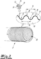
- the tank inner pipe 1 is designed as a corrugated pipe. This is especially in the Fig. 2 recognizable.
- the wave crests 8 and the wave troughs 9 preferably run over and over the entire circumference of the pipe 1 in the exemplary embodiment.
- the wave crests 8 and the wave troughs 9 have been recommended and, in the exemplary embodiment, have the same or constant distances a over the length of the pipeline 1.
Landscapes
- Engineering & Computer Science (AREA)
- Mechanical Engineering (AREA)
- Life Sciences & Earth Sciences (AREA)
- Sustainable Development (AREA)
- Sustainable Energy (AREA)
- Chemical & Material Sciences (AREA)
- Combustion & Propulsion (AREA)
- Transportation (AREA)
- Cooling, Air Intake And Gas Exhaust, And Fuel Tank Arrangements In Propulsion Units (AREA)
- Rigid Pipes And Flexible Pipes (AREA)
- Laminated Bodies (AREA)
Description
- Die Erfindung betrifft eine Tank-Innenrohrleitung, insbesondere in Kraftstofftanks von Kraftfahrzeugen, wobei die Rohrleitung einen von einer Rohrwandung umgebenen Fluidkanal aufweist. Die Erfindung betrifft fernerhin einen Tank mit zumindest einer solchen Tank-Innenrohrleitung. - Tank-Innenrohrleitung meint im Rahmen der Erfindung, dass die erfindungsgemäße Rohrleitung in dem Innenraum eines Tanks angeordnet ist bzw. durch den Innenraum eines Tanks verläuft. Dabei handelt es sich insbesondere um eine Tank-Innenrohrleitung, die durch den Innenraum eines Kraftstofftanks eines Kraftfahrzeuges verläuft. Insoweit betrifft die Erfindung vor allem eine Kraftfahrzeug-Tank-Innenrohrleitung. Die
US 2007/134458 A1 offenbart eine Rohrleitung, wobei die Rohrleitung einen von einer Rohrwandung umgebenen Fluidkanal aufweist, wobei die Rohrwandung aus zumindest drei Schichten besteht, wobei eine Außenschicht auf Basis eines aromatischen Polyamids vorgesehen ist, wobei eine Zwischenschicht vorhanden ist und wobei eine Innenschicht auf Basis eines aromatischen Polyamids vorgesehen ist. - Tank-Innenrohrleitungen sind grundsätzlich aus der Praxis in verschiedenen Ausführungsformen bekannt. Das gilt auch für Tank-Innenrohrleitungen in Kraftstofftanks von Kraftfahrzeugen. Diese Rohrleitungen sind bislang so ausgelegt, dass sie lediglich bis zu einer Temperatur von 70 °C beständig sind bzw. problemlos betrieben werden können. Außerdem haben viele dieser bekannten Rohrleitungen den Nachteil, dass mit dem durchströmenden Kraftstoff Komponenten aus dem Material der Rohrleitungswandung ausgewaschen werden können. Dadurch wird zumindest langfristig die Funktionsfähigkeit des Kraftstoffsystems negativ beeinträchtigt. Fernerhin sind viele dieser bekannten Rohrleitungen relativ aufwendig aufgebaut und/oder benötigen verhältnismäßig hohe Mengen an Kunststoffmaterial für die Rohrleitungswandungen. Insoweit sind die bekannten Tank-Innenrohrleitungen verbesserungsfähig.
- Der Erfindung liegt dementsprechend das technische Problem zugrunde, eine Tank-Innenrohrleitung der eingangs genannten Art anzugeben, die sich durch eine hohe Temperaturbeständigkeit, insbesondere bis zu Temperaturen von zumindest 120° auszeichnet, deren Wandungsmaterial gegen unerwünschte Auswaschungen beständig ist und die im Übrigen einfach und wenig aufwendig aufgebaut bzw. fertigbar ist. Der Erfindung liegt weiterhin das technische Problem zugrunde, einen Tank mit zumindest einer solchen Tank-Innenrohrleitung anzugeben.
- Zur Lösung dieses technischen Problems lehrt die Erfindung einen Tank gemäß Anspruch 1. Es liegt im Rahmen der Erfindung, dass die Außenschicht aus zumindest 80 Gew.-%, vorzugsweise aus zumindest 85 Gew.-%, bevorzugt aus zumindest 90 Gew.-% und sehr bevorzugt aus zumindest 95 Gew.-% eines aromatischen Polyamids und empfohlenermaßen aus Polyphthalamid (PPA) besteht. Nach einer sehr bewährten Ausführungsform besteht die Außenschicht aus zumindest 97 Gew.-%, bevorzugt aus zumindest 98 Gew.-% des aromatischen Polyamids, empfohlenermaßen aus Polyphthalamid (PPA). - Es empfiehlt sich, dass die Außenschicht eine Schichtdicke von 0,1 mm bis 1,3 mm, vorzugsweise von 0,2 mm bis 1,2 mm, bevorzugt von 0,2 mm bis 1 mm und sehr bevorzugt von 0,25 mm bis 0,9 mm aufweist. - Es liegt im Rahmen der Erfindung, dass die Außenschicht elektrisch leitfähig ausgebildet ist. Dazu weist die Außenschicht zweckmäßigerweise geeignete Leitfähigkeitszusätze - wie beispielsweise Ruß oder dergleichen - auf.
- Es empfiehlt sich, dass die Zwischenschicht aus zumindest 80 Gew.-%, vorzugsweise aus zumindest 85 Gew.-%, bevorzugt aus zumindest 90 Gew.-% und sehr bevorzugt aus zumindest 95 Gew.-% eines Polyamids und bevorzugt eines aliphatischen Polyamids besteht. Gemäß sehr bevorzugter Ausführungsform der Erfindung besteht die Zwischenschicht aus zumindest 97 Gew.-% und bevorzugt aus zumindest 98 Gew.-% aus dem Polyamid, empfohlenermaßen aus dem aliphatischen Polyamid. Eine besonders bewährte Ausführungsform der Erfindung ist dadurch gekennzeichnet, dass die Zwischenschicht auf Basis von Polyamid 6 ausgebildet ist. Nach einer anderen Ausführungsform ist die Zwischenschicht auf Basis von Polyamid 12 und/oder von Polyamid 6.6 ausgebildet. - Es empfiehlt sich, dass die Zwischenschicht eine Schichtdicke von 0,1 bis 1,3 mm, vorzugsweise von 0,2 bis 1,2 mm, bevorzugt von 0,2 mm bis 1 mm und sehr bevorzugt von 0,25 mm bis 0,9 mm aufweist. Grundsätzlich kann auch die Zwischenschicht elektrisch leitfähig ausgebildet sein.
- Es liegt im Rahmen der Erfindung, dass die Innenschicht der Rohrleitung aus zumindest 80 Gew.-%, vorzugsweise aus zumindest 85 Gew.-%, bevorzugt aus zumindest 90 Gew.-% und sehr bevorzugt aus zumindest 95 Gew.-% eines aromatischen Polyamids und empfohlenermaßen aus Polyphthalamid (PPA) besteht. Besonders bewährt hat sich im Rahmen der Erfindung, dass die Innenschicht aus zumindest 97 Gew.-% und bevorzugt aus zumindest 98 Gew.-% des aromatischen Polyamids und empfohlenermaßen des Polyphthalamids (PPA) besteht. - Es empfiehlt sich, dass die Innenschicht der Rohrleitung eine Schichtdicke von 0,1 mm bis 1,3 mm, vorzugsweise von 0,2 mm bis 1,2 mm, bevorzugt von 0,2 mm bis 1 mm und besonders bevorzugt von 0,25 mm bis 0,9 mm aufweist. - Es hat sich bewährt, dass die Außenschicht elektrisch leitfähig eingerichtet ist. Hierzu wird die Außenschicht zweckmäßigerweise mit geeigneten Leitfähigkeitszusätzen - beispielsweise mit Ruß oder dergleichen - versehen.
- Eine bevorzugte Ausführungsform der Erfindung zeichnet sich dadurch aus, dass die Zwischenschicht eine höhere Schichtdicke aufweist als die Außenschicht und/oder die Innenschicht. Zweckmäßigerweise ist die Zwischenschicht als dickste Schicht der Rohrwandung der erfindungsgemäßen Tank-Innenrohrleitung ausgebildet. Vorzugsweise ist die Zwischenschicht 1,1-bis 2,5-mal und bevorzugt 1,2- bis 2-mal sowie sehr bevorzugt 1,2- bis 1,8-mal so dick wie die Außenschicht und/oder die Innenschicht. - Gemäß bewährter Ausführungsvariante der Erfindung ist sowohl die Außenschicht als auch die Innenschicht elektrisch leitfähig eingerichtet. Grundsätzlich kann auch die Zwischenschicht elektrisch leitfähig eingerichtet sein.
- Eine besonders empfohlene Ausführungsform der Erfindung ist dadurch gekennzeichnet, dass die erfindungsgemäße Tank-Innenrohrleitung lediglich die drei Schichten mit Außenschicht, Zwischenschicht und Innenschicht aufweist. Grundsätzlich kann die erfindungsgemäße Tank-Innenrohrleitung aber noch über weitere Schichten verfügen. So kann die Außenschicht mit der Zwischenschicht über eine Adhäsivschicht verbunden sein, welche Adhäsivschicht die Haftung zwischen Außenschicht und Zwischenschicht verbessert. Alternativ oder zusätzlich kann die Zwischenschicht mit der Innenschicht über eine Adhäsivschicht verbunden sein, welche Adhäsivschicht die Haftung zwischen der Innenschicht und der Zwischenschicht verbessert. Es liegt auch im Rahmen der Erfindung, dass zwischen der Außenschicht und der Innenschicht zumindest eine Barriereschicht mit Barriereeigenschaften bezüglich des durch die Rohrleitung geleiteten Kraftstoffes bzw. bezüglich einer Komponente dieses Kraftstoffes angeordnet ist.
- Gemäß einer Ausführungsvariante ist die Tank-Innenrohrleitung an eine in dem zugeordneten Tank - insbesondere in dem zugeordneten Kraftstofftank des Kraftfahrzeuges - angeordnete Pumpe angeschlossen. Mit der Pumpe wird das im Tank vorhandene fluide Medium bzw. der im Kraftstofftank angeordnete Kraftstoff durch die Tank-Innenrohrleitung gefördert. Die erfindungsgemäße Tank-Innenrohrleitung kann aber auch zum Druckausgleich und/oder zum Niveau-Ausgleich zwischen verschiedenen Bereichen des Tanks bzw. Kraftstofftanks dienen. In jedem Fall ist die erfindungsgemäße Tank-Innenrohrleitung im Inneren bzw. im Innenraum eines Tanks bzw. Kraftstofftanks angeordnet.
- Eine besonders bevorzugte Ausführungsform der Erfindung ist dadurch gekennzeichnet, dass die erfindungsgemäße Tank-Innenrohrleitung zumindest bereichsweise - vorzugsweise vollständig - in Form eines Wellrohres ausgestaltet ist. Es liegt dabei im Rahmen der Erfindung, dass die Wellenberge und Wellentäler der Rohrleitung über den Umfang der Rohrleitung umlaufen. Zweckmäßigerweise haben die Wellenberge und die Wellentäler der Rohrleitung über zumindest einen Teil der Länge der Rohrleitung, vorzugsweise über die gesamte Länge bzw. im Wesentlichen über die gesamte Länge der Rohrleitung gleiche/konstante Abstände voneinander bzw. im Wesentlichen gleiche/konstante Abstände voneinander. Die Ausführungsform als Wellrohr hat sich im Rahmen der Erfindung besonders bewährt. Diese Ausgestaltung weist Gemäß einer Ausführungsform des Tanks ist dabei die Tank-Innenrohrleitung zumindest bereichsweise an der Wandung des Tanks bzw. Kraftstofftanks angeordnet. Grundsätzlich kann die Tank-Innenrohrleitung aber auch durch andere Bereiche des Tanks bzw. Kraftstofftanks verlaufen.
- Der Erfindung liegt die Erkenntnis zugrunde, dass sich die erfindungsgemäße Tank-Innenrohrleitung durch eine hervorragende Temperaturbeständigkeit und zudem auch durch eine optimale mechanische Widerstandsfähigkeit auszeichnet. Die erfindungsgemäßen Rohrleitungen sind bei Temperaturen von -40 °C bis zu 120 °C und mehr beständig und können somit für verschiedenste Zwecke in Tanks, insbesondere in Kraftstofftanks von Kraftfahrzeugen zum Einsatz kommen. Der Erfindung liegt insoweit auch die Erkenntnis zugrunde, dass zunehmend temperaturbeständigere Rohrleitungen für den Innenraum von Tanks bzw. Kraftstofftanks notwendig werden. - Die erfindungsgemäßen Tank-Innenrohrleitungen erweisen sich auch bei der Herstellung eines Tanks nach dem Ship-in-Bottle-Prinzip als sehr vorteilhaft. Dabei wird ein Schlauch aus dem Tankwandungsmaterial mit allen erforderlichen Aggregaten - wie beispielsweise Pumpe, Füllstandssensor und dergleichen - bestückt und dann durch Aufblasen in die gewünschte Form gebracht. Dazu wird der Schlauch relativ stark aufgeheizt. Die erfindungsgemäßen Tank-Innenrohrleitungen - die ebenfalls in dem Schlauch angeordnet wurden - überstehen diese Behandlung ohne Probleme. - Von besonderem Vorteil ist bei der erfindungsgemäßen Tank-Innenrohrleitung weiterhin, dass sie problemlos und ohne Einschränkungen auch für unterschiedliche Kraftstoffarten - wie Benzin oder Diesel - einsetzbar ist. Die erfindungsgemäße Rohrleitung zeichnet sich fernerhin auch durch eine optimale chemische Beständigkeit aus. Auswaschungen von Kunststoffkomponenten durch den durch die Rohrleitung geleiteten Kraftstoff finden quasi nicht statt bzw. nur in vernachlässigbarem Ausmaß statt. Die erfindungsgemäße Tank-Innenrohrleitung genügt weiterhin auch allen mechanischen Anforderungen. Fernerhin ist sie auf einfache und wenig aufwendige Weise und insbesondere materialsparende Weise herstellbar.
- Nachfolgend wird die Erfindung anhand einer lediglich ein Ausführungsbeispiel darstellenden Zeichnung näher erläutert. Es zeigen in schematischer Darstellung:
- Fig. 1
- einen Schnitt durch einen Kraftstofftank eines Kraftfahrzeuges mit einer erfindungsgemäßen Tank-Innenrohrleitung und
- Fig. 2
- die erfindungsgemäße Tank-Innenrohrleitung in perspektivischer Darstellung.
- In den Figuren ist eine erfindungsgemäße Tank-Innenrohrleitung 1 dargestellt, die sich bevorzugt und im Ausführungsbespiel in einem Kraftstofftank 2 eines Kraftfahrzeuges befindet. In einem mit der erfindungsgemäßen Rohrleitung 1 versehenen Kraftstofftank 2 können grundsätzlich verschiedene Arten von Kraftstoffen, beispielsweise Dieselkraftstoff oder Benzin aufgenommen werden. Die erfindungsgemäße Rohrleitung 1 weist wie üblich einen von einer Rohrwandung 3 umgebenen Fluidkanal 4 auf.
- Nach einer bevorzugten Ausführungsform und im Ausführungsbeispiel weist die Rohrwandung 3 drei Schichten 5, 6, 7 auf. Die Außenschicht 5 besteht vorzugsweise und im Ausführungsbeispiel aus Polyphthalamid (PPA) bzw. im Wesentlichen aus Polyphthalamid (PPA). Neben Polyphthalamid (PPA) kann die Außenschicht 5 Zusätze, wie Leitfähigkeitszusätze oder stabilisierende Zusätze oder dergleichen aufweisen. Im Ausführungsbeispiel ist unmittelbar an die Außenschicht 5 eine Zwischenschicht 6 angeschlossen, die empfohlenermaßen und im Ausführungsbeispiel aus einem aliphatischen Polyamid bzw. im Wesentlichen aus einem aliphatischen Polyamid besteht und zwar bevorzugt und im Ausführungsbeispiel aus Polyamid 6. Außerdem kann die Zwischenschicht 6 Zusätze, wie Leitfähigkeitszusätze, stabilisierende Zusätze und dergleichen aufweisen. Bevorzugt und im Ausführungsbeispiel ist unmittelbar an die Zwischenschicht 6 die Innenschicht 7 angeschlossen. Diese Innenschicht 7 besteht empfohlenermaßen und im Ausführungsbeispiel aus Polyphthalamid (PPA) bzw. im Wesentlichen aus Polyphthalamid (PPA). Weiterhin kann auch diese Innenschicht 7 Zusätze wie Leitfähigkeitszusätze, Stabilisierungszusätze und dergleichen enthalten.
- Vorzugsweise und im Ausführungsbeispiel liegt die Gesamtwandstärke der Rohrwandung 3 zwischen 0,8 und 2,0 mm. Die Schichtdicken der drei Schichten 5, 6, 7 betragen empfohlenermaßen und im Ausführungsbeispiel jeweils 15 bis 45% der Gesamtwandstärke. Bevorzugt und im Ausführungsbeispiel ist die Zwischenschicht 6 dicker ausgebildet als die Außenschicht 5 und auch dicker ausgebildet als die Innenschicht 7. Diese Ausführungsform hat sich im Rahmen der Erfindung besonders bewährt.
- Vorzugsweise und im Ausführungsbeispiel sind alle drei Schichten 5, 6, 7 elektrisch leitfähig ausgebildet. Dazu weisen die Schichten 5, 6, 7 geeignete Leitfähigkeitszusätze, wie Ruß oder dergleichen auf. - Nach ganz besonders bevorzugter Ausführungsform und im Ausführungsbeispiel ist die erfindungsgemäße Tank-Innenrohrleitung 1 als Wellrohr ausgebildet. Das ist insbesondere in der
Fig. 2 erkennbar. Bei dieser wellrohrförmig ausgebildeten Tank-Innenrohrleitung 1 laufen die Wellenberge 8 und die Wellentäler 9 bevorzugt und im Ausführungsbeispiel über den gesamten Umfang der Rohrleitung 1 um. Die Wellenberge 8 und die Wellentäler 9 haben im Übrigen empfohlenermaßen und im Ausführungsbeispiel gleiche bzw. konstante Abstände a über die Länge der Rohrleitung 1 gesehen.
Claims (14)
- Tank, insbesondere Kraftstofftank (2) für Kraftfahrzeuge, mit zumindest einer im Innenraum des Tanks angeordneten Tank-Innenrohrleitung (1), wobei die Tank-Innenrohrleitung (1) einen von einer Rohrwandung (3) umgebenen Fluidkanal aufweist, wobei die Rohrwandung (3) aus zumindest drei Schichten besteht, wobei eine Außenschicht (5) auf Basis eines aromatischen Polyamids, insbesondere auf Basis von Polyphthalamid (PPA) vorgesehen ist, wobei eine Zwischenschicht (6) auf Basis eines aliphatischen Polyamids vorhanden ist, wobei eine Innenschicht (7) auf Basis eines aromatischen Polyamids, insbesondere auf Basis von Polyphthalamid (PPA) vorgesehen ist und wobei die gesamte Wandstärke der Tank-Innenrohrleitung (1) 0,5 mm bis 3,5 mm, vorzugsweise 0,6 mm bis 3 mm und bevorzugt 0,6 mm bis 2,5 mm beträgt.
- Tank nach Anspruch 1, wobei die Außenschicht (5) der Tank-Innenrohrleitung (1) aus zumindest 80 Gew.-%, vorzugsweise aus zumindest 85 Gew.-% und bevorzugt aus zumindest 90 Gew.-% eines aromatischen Polyamids, insbesondere Polyphthalamid besteht.
- Tank nach einem der Ansprüche 1 oder 2, wobei die Außenschicht (5) der Tank-Innenrohrleitung (1) eine Schichtdicke von 0,1 mm bis 1,3 mm, vorzugsweise von 0,2 mm bis 1,2 mm und bevorzugt von 0,2 mm bis 1 mm aufweist.
- Tank nach einem der Ansprüche 1 bis 3, wobei die Zwischenschicht (6) der Tank-Innenrohrleitung (1) aus zumindest 80 Gew.-%, vorzugsweise aus zumindest 85 Gew.-% und bevorzugt aus zumindest 90 Gew.-% Polyamid bzw. aliphatischem Polyamid besteht.
- Tank nach einem der Ansprüche 1 bis 4, wobei die Zwischenschicht (6) der Tank-Innenrohrleitung (1) auf Basis von Polyamid 6 ausgebildet ist.
- Tank nach einem der Ansprüche 1 bis 5, wobei die Zwischenschicht (6) der Tank-Innenrohrleitung (1) eine Schichtdicke von 0,1 mm bis 1,3 mm, vorzugsweise von 0,2 mm bis 1,2 mm und bevorzugt von 0,2 mm bis 1 mm aufweist.
- Tank nach einem der Ansprüche 1 bis 6, wobei die Innenschicht (7) der Tank-Innenrohrleitung (1) aus zumindest 80 Gew.-%, vorzugsweise aus zumindest 85 Gew-% und bevorzugt aus zumindest 90 Gew.-% eines aromatischen Polyamids, insbesondere Polyphthalamid besteht.
- Tank nach einem der Ansprüche 1 bis 7, wobei die Innenschicht (7) der Tank-Innenrohrleitung (1) eine Schichtdicke von 0,1 mm bis 1,3 mm, vorzugsweise von 0,2 mm bis 1,2 mm und bevorzugt von 0,2 mm bis 1 mm aufweist.
- Tank nach einem der Ansprüche 1 bis 8, wobei die Innenschicht (7) und/oder die Zwischenschicht (6) und/oder die Außenschicht (5) der Tank-Innenrohrleitung(1) elektrisch leitfähig ausgebildet ist/sind.
- Tank nach einem der Ansprüche 1 bis 9, wobei die Tank-Innenrohrleitung (1) lediglich die drei Schichten mit Außenschicht (5), Zwischenschicht (6) und Innenschicht (7) aufweist.
- Tank nach einem der Ansprüche 1 bis 10, wobei die Zwischenschicht (6) dicker ist als die Außenschicht (5) und/oder dicker ist als die Innenschicht (7) Tank-Innenrohrleitung (1).
- Tank nach einem der Ansprüche 1 bis 9 oder 11, wobei die Außenschicht (5) der Tank-Innenrohrleitung (1) mit der Zwischenschicht (6) über zumindest eine Adhäsivschicht verbunden ist und/oder wobei die Zwischenschicht (6) der Tank-Innenrohrleitung (1) mit der Innenschicht (7) über zumindest eine Adhäsivschicht verbunden ist.
- Tank nach einem der Ansprüche 1 bis 12, wobei die Tank-Innenrohrleitung (1) an eine im Tank, insbesondere im Kraftstofftank (2) des Kraftfahrzeuges, angeordnete Pumpe angeschlossen ist.
- Tank nach einem der Ansprüche 1 bis 13, wobei die Tank-Innenrohrleitung (1) zumindest bereichsweise in Form eines Wellrohres ausgestaltet ist.
Priority Applications (7)
| Application Number | Priority Date | Filing Date | Title |
|---|---|---|---|
| EP15195886.5A EP3170656B1 (de) | 2015-11-23 | 2015-11-23 | Tank-innenrohrleitung und tank mit zumindest einer tank-innenrohrleitung |
| US15/776,090 US20180370179A1 (en) | 2015-11-23 | 2016-11-08 | Internal tank tube and tank having at least one internal tube |
| CN201680079705.4A CN108495747A (zh) | 2015-11-23 | 2016-11-08 | 罐体内管和具有至少一个内管的罐体 |
| JP2018526553A JP6606285B2 (ja) | 2015-11-23 | 2016-11-08 | タンク内部配管系及び少なくとも1つのタンク内部配管系を有するタンク |
| PCT/EP2016/076910 WO2017089113A1 (de) | 2015-11-23 | 2016-11-08 | Tank-innenrohrleitung und tank mit zumindest einer tank-innenrohrleitung |
| MX2018006323A MX376296B (es) | 2015-11-23 | 2016-11-08 | Tubería interna para tanque y tanque que tiene al menos una tubería interna. |
| KR1020187017892A KR102119587B1 (ko) | 2015-11-23 | 2016-11-08 | 탱크의 내부관과, 적어도 하나의 내부관을 구비하는 탱크 |
Applications Claiming Priority (1)
| Application Number | Priority Date | Filing Date | Title |
|---|---|---|---|
| EP15195886.5A EP3170656B1 (de) | 2015-11-23 | 2015-11-23 | Tank-innenrohrleitung und tank mit zumindest einer tank-innenrohrleitung |
Publications (2)
| Publication Number | Publication Date |
|---|---|
| EP3170656A1 EP3170656A1 (de) | 2017-05-24 |
| EP3170656B1 true EP3170656B1 (de) | 2018-08-01 |
Family
ID=54703831
Family Applications (1)
| Application Number | Title | Priority Date | Filing Date |
|---|---|---|---|
| EP15195886.5A Active EP3170656B1 (de) | 2015-11-23 | 2015-11-23 | Tank-innenrohrleitung und tank mit zumindest einer tank-innenrohrleitung |
Country Status (7)
| Country | Link |
|---|---|
| US (1) | US20180370179A1 (de) |
| EP (1) | EP3170656B1 (de) |
| JP (1) | JP6606285B2 (de) |
| KR (1) | KR102119587B1 (de) |
| CN (1) | CN108495747A (de) |
| MX (1) | MX376296B (de) |
| WO (1) | WO2017089113A1 (de) |
Families Citing this family (2)
| Publication number | Priority date | Publication date | Assignee | Title |
|---|---|---|---|---|
| EP3530454B1 (de) * | 2018-02-22 | 2020-06-10 | TI Automotive (Fuldabrück) GmbH | Mehrschichtige kraftfahrzeug-rohrleitung |
| US20230264459A1 (en) * | 2022-01-10 | 2023-08-24 | Cooper-Standard Automotive Inc. | High temperature multi-layer coolant tube |
Citations (2)
| Publication number | Priority date | Publication date | Assignee | Title |
|---|---|---|---|---|
| EP2738031A1 (de) * | 2012-11-30 | 2014-06-04 | Magna Steyr Fuel Systems GesmbH | Tanksystem für ein Kraftfahrzeug |
| WO2015033982A1 (ja) * | 2013-09-04 | 2015-03-12 | 宇部興産株式会社 | 積層チューブ |
Family Cites Families (17)
| Publication number | Priority date | Publication date | Assignee | Title |
|---|---|---|---|---|
| US5524673A (en) * | 1992-04-14 | 1996-06-11 | Itt Corporation | Multi-layer tubing having electrostatic dissipation for handling hydrocarbon fluids |
| FR2812929B1 (fr) * | 2000-08-11 | 2004-01-09 | Nobel Plastiques | Tube multicouche en matiere plastique pour fluides utilises dans les vehicules automobiles |
| FR2838501B1 (fr) * | 2002-04-15 | 2005-07-01 | Nobel Plastiques | Tube de transport d'un fluide automobile |
| ES2385439T3 (es) * | 2003-08-19 | 2012-07-24 | Solvay Specialty Polymers Usa, Llc. | Cuerpo hueco de poliamida modificada para impacto |
| JP2005178076A (ja) * | 2003-12-17 | 2005-07-07 | Ube Ind Ltd | 積層チュ−ブ |
| EP1711732A1 (de) * | 2004-02-06 | 2006-10-18 | Cooper-Standard Automotive Inc. | Rohrleitungen aus aromatischem polyamid für fahrzeuganwendungen |
| KR20070017313A (ko) * | 2004-02-06 | 2007-02-09 | 쿠퍼-스탠다드 오토모티브 인코포레이티드 | 차량 적용을 위한 방향족 폴리아미드 튜빙 |
| EP1741553B1 (de) * | 2004-04-27 | 2011-10-05 | Ube Industries, Ltd. | Mehrlagige struktur |
| FR2874987B1 (fr) * | 2004-09-08 | 2006-12-01 | Nobel Plastiques Soc Par Actio | Conduite multicouche pa/po-pa/tpe-e |
| US7467549B2 (en) * | 2005-04-05 | 2008-12-23 | Ti Group Automotive Systems, Llc | Electrostatic charge control for in-tank fuel module components |
| US7140247B2 (en) * | 2005-04-05 | 2006-11-28 | Ti Group Automotive Systems, Llc | Electrostatic charge control for in-tank fuel module components |
| CN1903613A (zh) * | 2005-04-05 | 2007-01-31 | Ti集团车辆系统有限责任公司 | 箱内燃油模块组件的静电电荷控制 |
| JP4860213B2 (ja) * | 2005-09-06 | 2012-01-25 | 三桜工業株式会社 | 多層樹脂チューブ |
| JP2008018702A (ja) * | 2006-07-14 | 2008-01-31 | Nitta Moore Co | チューブ |
| FR2906862A1 (fr) * | 2006-10-10 | 2008-04-11 | Nobel Plastiques Soc Par Actio | Canalisation ppa/fluoropolymere |
| JP2011178207A (ja) * | 2010-02-26 | 2011-09-15 | Tokai Rubber Ind Ltd | 自動車燃料用インタンクチューブおよびその製法 |
| BR112017019632B1 (pt) * | 2015-03-20 | 2022-08-09 | Kuraray Co., Ltd | Tubo de múltiplas camadas para o transporte de combustível |
-
2015
- 2015-11-23 EP EP15195886.5A patent/EP3170656B1/de active Active
-
2016
- 2016-11-08 KR KR1020187017892A patent/KR102119587B1/ko not_active Expired - Fee Related
- 2016-11-08 WO PCT/EP2016/076910 patent/WO2017089113A1/de not_active Ceased
- 2016-11-08 US US15/776,090 patent/US20180370179A1/en not_active Abandoned
- 2016-11-08 CN CN201680079705.4A patent/CN108495747A/zh active Pending
- 2016-11-08 JP JP2018526553A patent/JP6606285B2/ja active Active
- 2016-11-08 MX MX2018006323A patent/MX376296B/es active IP Right Grant
Patent Citations (2)
| Publication number | Priority date | Publication date | Assignee | Title |
|---|---|---|---|---|
| EP2738031A1 (de) * | 2012-11-30 | 2014-06-04 | Magna Steyr Fuel Systems GesmbH | Tanksystem für ein Kraftfahrzeug |
| WO2015033982A1 (ja) * | 2013-09-04 | 2015-03-12 | 宇部興産株式会社 | 積層チューブ |
Also Published As
| Publication number | Publication date |
|---|---|
| MX376296B (es) | 2025-03-07 |
| KR102119587B1 (ko) | 2020-06-17 |
| KR20180088417A (ko) | 2018-08-03 |
| CN108495747A (zh) | 2018-09-04 |
| WO2017089113A1 (de) | 2017-06-01 |
| EP3170656A1 (de) | 2017-05-24 |
| MX2018006323A (es) | 2018-08-29 |
| JP6606285B2 (ja) | 2019-11-13 |
| US20180370179A1 (en) | 2018-12-27 |
| JP2018536801A (ja) | 2018-12-13 |
Similar Documents
| Publication | Publication Date | Title |
|---|---|---|
| DE102007058721B4 (de) | Mehrschichtige Leitung | |
| EP1519098A1 (de) | Elektrisch beheizbare Flüssigkeitsleitung | |
| DE202017101274U1 (de) | Verbindungsaggregat | |
| EP2204628A1 (de) | Kunststoff-Wärmeübertrager | |
| DE3443085A1 (de) | Doppelrohr-waermetauscher | |
| EP3170656B1 (de) | Tank-innenrohrleitung und tank mit zumindest einer tank-innenrohrleitung | |
| DE102008048512A1 (de) | Montagestrukturen für Rohrleitungselemente | |
| WO2016023797A1 (de) | Fluidleitung | |
| EP2801743A1 (de) | Verfahren zur Verbindung eines Leitungsverbinders mit einer fluidführenden Kraftfahrzeugleitung | |
| DE3106814A1 (de) | "biegsame rohrleitung, insbesondere fuer den transport von fluessigkeiten mit hohen temperaturen und/oder hohem druck und rohr mit einer derartigen rohrleitung | |
| DE2606113A1 (de) | Verfahren und vorrichtung zum verhindern des aussulzens von dieseltreibstoffen | |
| DE102015120508A1 (de) | Verbindungsanordnung für ein Kühlmittelsystem und Verfahren zur Herstellung einer Verbindungsanordnung | |
| EP3575655B1 (de) | Rohrleitungs-befestigungsaggregat und verfahren zur befestigung einer rohrleitung an einem befestigungsclip | |
| DE102015226795A1 (de) | Komponente einer hydraulischen Einrichtung, insbesondere einer Brennstoffeinspritzanlage für Brennkraftmaschinen | |
| DE102016201609A1 (de) | Brennkraftmaschinensystem | |
| DE102012005026A1 (de) | Flexible Schlauchleitung | |
| DE102018216283A1 (de) | Elektrische Heizeinrichtung | |
| DE19908012A1 (de) | Einrichtung zum Ausgleich der Bewegung zweier druckdicht zu verbindender Rohre | |
| DE202012009932U1 (de) | Behälter, hergestellt aus einem wendelförmig gebogenen Blechband | |
| EP3392033B1 (de) | Tank-innenrohrleitung, insbesondere in kraftstofftanks von kraftfahrzeugen | |
| EP4079502A1 (de) | Mehrschichtige rohrleitung | |
| DE202007007125U1 (de) | Heizmittel zur Erwärmung eines Fluids | |
| DE102009030866B4 (de) | Abgasrohr für eine Verbrennungskraftmaschine | |
| DE102007049683B4 (de) | Schwingungsdämpferlagerung | |
| DE102009038429A1 (de) | Kraftstoffeinspritzsystem für Brennkraftmaschinen sowie Verfahren zur Herstellung |
Legal Events
| Date | Code | Title | Description |
|---|---|---|---|
| PUAI | Public reference made under article 153(3) epc to a published international application that has entered the european phase |
Free format text: ORIGINAL CODE: 0009012 |
|
| 17P | Request for examination filed |
Effective date: 20161104 |
|
| AK | Designated contracting states |
Kind code of ref document: A1 Designated state(s): AL AT BE BG CH CY CZ DE DK EE ES FI FR GB GR HR HU IE IS IT LI LT LU LV MC MK MT NL NO PL PT RO RS SE SI SK SM TR |
|
| AX | Request for extension of the european patent |
Extension state: BA ME |
|
| 17Q | First examination report despatched |
Effective date: 20170608 |
|
| GRAP | Despatch of communication of intention to grant a patent |
Free format text: ORIGINAL CODE: EPIDOSNIGR1 |
|
| INTG | Intention to grant announced |
Effective date: 20180309 |
|
| GRAS | Grant fee paid |
Free format text: ORIGINAL CODE: EPIDOSNIGR3 |
|
| GRAA | (expected) grant |
Free format text: ORIGINAL CODE: 0009210 |
|
| AK | Designated contracting states |
Kind code of ref document: B1 Designated state(s): AL AT BE BG CH CY CZ DE DK EE ES FI FR GB GR HR HU IE IS IT LI LT LU LV MC MK MT NL NO PL PT RO RS SE SI SK SM TR |
|
| REG | Reference to a national code |
Ref country code: GB Ref legal event code: FG4D Free format text: NOT ENGLISH |
|
| REG | Reference to a national code |
Ref country code: CH Ref legal event code: EP Ref country code: AT Ref legal event code: REF Ref document number: 1023813 Country of ref document: AT Kind code of ref document: T Effective date: 20180815 |
|
| REG | Reference to a national code |
Ref country code: IE Ref legal event code: FG4D Free format text: LANGUAGE OF EP DOCUMENT: GERMAN |
|
| REG | Reference to a national code |
Ref country code: DE Ref legal event code: R096 Ref document number: 502015005289 Country of ref document: DE |
|
| REG | Reference to a national code |
Ref country code: NL Ref legal event code: MP Effective date: 20180801 |
|
| REG | Reference to a national code |
Ref country code: LT Ref legal event code: MG4D |
|
| PG25 | Lapsed in a contracting state [announced via postgrant information from national office to epo] |
Ref country code: NO Free format text: LAPSE BECAUSE OF FAILURE TO SUBMIT A TRANSLATION OF THE DESCRIPTION OR TO PAY THE FEE WITHIN THE PRESCRIBED TIME-LIMIT Effective date: 20181101 Ref country code: BG Free format text: LAPSE BECAUSE OF FAILURE TO SUBMIT A TRANSLATION OF THE DESCRIPTION OR TO PAY THE FEE WITHIN THE PRESCRIBED TIME-LIMIT Effective date: 20181101 Ref country code: LT Free format text: LAPSE BECAUSE OF FAILURE TO SUBMIT A TRANSLATION OF THE DESCRIPTION OR TO PAY THE FEE WITHIN THE PRESCRIBED TIME-LIMIT Effective date: 20180801 Ref country code: NL Free format text: LAPSE BECAUSE OF FAILURE TO SUBMIT A TRANSLATION OF THE DESCRIPTION OR TO PAY THE FEE WITHIN THE PRESCRIBED TIME-LIMIT Effective date: 20180801 Ref country code: PL Free format text: LAPSE BECAUSE OF FAILURE TO SUBMIT A TRANSLATION OF THE DESCRIPTION OR TO PAY THE FEE WITHIN THE PRESCRIBED TIME-LIMIT Effective date: 20180801 Ref country code: IS Free format text: LAPSE BECAUSE OF FAILURE TO SUBMIT A TRANSLATION OF THE DESCRIPTION OR TO PAY THE FEE WITHIN THE PRESCRIBED TIME-LIMIT Effective date: 20181201 Ref country code: SE Free format text: LAPSE BECAUSE OF FAILURE TO SUBMIT A TRANSLATION OF THE DESCRIPTION OR TO PAY THE FEE WITHIN THE PRESCRIBED TIME-LIMIT Effective date: 20180801 Ref country code: RS Free format text: LAPSE BECAUSE OF FAILURE TO SUBMIT A TRANSLATION OF THE DESCRIPTION OR TO PAY THE FEE WITHIN THE PRESCRIBED TIME-LIMIT Effective date: 20180801 Ref country code: GR Free format text: LAPSE BECAUSE OF FAILURE TO SUBMIT A TRANSLATION OF THE DESCRIPTION OR TO PAY THE FEE WITHIN THE PRESCRIBED TIME-LIMIT Effective date: 20181102 Ref country code: FI Free format text: LAPSE BECAUSE OF FAILURE TO SUBMIT A TRANSLATION OF THE DESCRIPTION OR TO PAY THE FEE WITHIN THE PRESCRIBED TIME-LIMIT Effective date: 20180801 |
|
| PG25 | Lapsed in a contracting state [announced via postgrant information from national office to epo] |
Ref country code: AL Free format text: LAPSE BECAUSE OF FAILURE TO SUBMIT A TRANSLATION OF THE DESCRIPTION OR TO PAY THE FEE WITHIN THE PRESCRIBED TIME-LIMIT Effective date: 20180801 Ref country code: LV Free format text: LAPSE BECAUSE OF FAILURE TO SUBMIT A TRANSLATION OF THE DESCRIPTION OR TO PAY THE FEE WITHIN THE PRESCRIBED TIME-LIMIT Effective date: 20180801 Ref country code: HR Free format text: LAPSE BECAUSE OF FAILURE TO SUBMIT A TRANSLATION OF THE DESCRIPTION OR TO PAY THE FEE WITHIN THE PRESCRIBED TIME-LIMIT Effective date: 20180801 |
|
| PG25 | Lapsed in a contracting state [announced via postgrant information from national office to epo] |
Ref country code: EE Free format text: LAPSE BECAUSE OF FAILURE TO SUBMIT A TRANSLATION OF THE DESCRIPTION OR TO PAY THE FEE WITHIN THE PRESCRIBED TIME-LIMIT Effective date: 20180801 Ref country code: CZ Free format text: LAPSE BECAUSE OF FAILURE TO SUBMIT A TRANSLATION OF THE DESCRIPTION OR TO PAY THE FEE WITHIN THE PRESCRIBED TIME-LIMIT Effective date: 20180801 Ref country code: IT Free format text: LAPSE BECAUSE OF FAILURE TO SUBMIT A TRANSLATION OF THE DESCRIPTION OR TO PAY THE FEE WITHIN THE PRESCRIBED TIME-LIMIT Effective date: 20180801 Ref country code: RO Free format text: LAPSE BECAUSE OF FAILURE TO SUBMIT A TRANSLATION OF THE DESCRIPTION OR TO PAY THE FEE WITHIN THE PRESCRIBED TIME-LIMIT Effective date: 20180801 Ref country code: ES Free format text: LAPSE BECAUSE OF FAILURE TO SUBMIT A TRANSLATION OF THE DESCRIPTION OR TO PAY THE FEE WITHIN THE PRESCRIBED TIME-LIMIT Effective date: 20180801 |
|
| REG | Reference to a national code |
Ref country code: DE Ref legal event code: R097 Ref document number: 502015005289 Country of ref document: DE |
|
| PG25 | Lapsed in a contracting state [announced via postgrant information from national office to epo] |
Ref country code: SK Free format text: LAPSE BECAUSE OF FAILURE TO SUBMIT A TRANSLATION OF THE DESCRIPTION OR TO PAY THE FEE WITHIN THE PRESCRIBED TIME-LIMIT Effective date: 20180801 Ref country code: SM Free format text: LAPSE BECAUSE OF FAILURE TO SUBMIT A TRANSLATION OF THE DESCRIPTION OR TO PAY THE FEE WITHIN THE PRESCRIBED TIME-LIMIT Effective date: 20180801 Ref country code: DK Free format text: LAPSE BECAUSE OF FAILURE TO SUBMIT A TRANSLATION OF THE DESCRIPTION OR TO PAY THE FEE WITHIN THE PRESCRIBED TIME-LIMIT Effective date: 20180801 |
|
| PLBE | No opposition filed within time limit |
Free format text: ORIGINAL CODE: 0009261 |
|
| STAA | Information on the status of an ep patent application or granted ep patent |
Free format text: STATUS: NO OPPOSITION FILED WITHIN TIME LIMIT |
|
| REG | Reference to a national code |
Ref country code: CH Ref legal event code: PL |
|
| 26N | No opposition filed |
Effective date: 20190503 |
|
| PG25 | Lapsed in a contracting state [announced via postgrant information from national office to epo] |
Ref country code: LU Free format text: LAPSE BECAUSE OF NON-PAYMENT OF DUE FEES Effective date: 20181123 Ref country code: MC Free format text: LAPSE BECAUSE OF FAILURE TO SUBMIT A TRANSLATION OF THE DESCRIPTION OR TO PAY THE FEE WITHIN THE PRESCRIBED TIME-LIMIT Effective date: 20180801 |
|
| REG | Reference to a national code |
Ref country code: BE Ref legal event code: MM Effective date: 20181130 |
|
| REG | Reference to a national code |
Ref country code: IE Ref legal event code: MM4A |
|
| PG25 | Lapsed in a contracting state [announced via postgrant information from national office to epo] |
Ref country code: LI Free format text: LAPSE BECAUSE OF NON-PAYMENT OF DUE FEES Effective date: 20181130 Ref country code: SI Free format text: LAPSE BECAUSE OF FAILURE TO SUBMIT A TRANSLATION OF THE DESCRIPTION OR TO PAY THE FEE WITHIN THE PRESCRIBED TIME-LIMIT Effective date: 20180801 Ref country code: CH Free format text: LAPSE BECAUSE OF NON-PAYMENT OF DUE FEES Effective date: 20181130 |
|
| PG25 | Lapsed in a contracting state [announced via postgrant information from national office to epo] |
Ref country code: IE Free format text: LAPSE BECAUSE OF NON-PAYMENT OF DUE FEES Effective date: 20181123 |
|
| PG25 | Lapsed in a contracting state [announced via postgrant information from national office to epo] |
Ref country code: BE Free format text: LAPSE BECAUSE OF NON-PAYMENT OF DUE FEES Effective date: 20181130 |
|
| PG25 | Lapsed in a contracting state [announced via postgrant information from national office to epo] |
Ref country code: MT Free format text: LAPSE BECAUSE OF FAILURE TO SUBMIT A TRANSLATION OF THE DESCRIPTION OR TO PAY THE FEE WITHIN THE PRESCRIBED TIME-LIMIT Effective date: 20180801 |
|
| PG25 | Lapsed in a contracting state [announced via postgrant information from national office to epo] |
Ref country code: TR Free format text: LAPSE BECAUSE OF FAILURE TO SUBMIT A TRANSLATION OF THE DESCRIPTION OR TO PAY THE FEE WITHIN THE PRESCRIBED TIME-LIMIT Effective date: 20180801 |
|
| PG25 | Lapsed in a contracting state [announced via postgrant information from national office to epo] |
Ref country code: PT Free format text: LAPSE BECAUSE OF FAILURE TO SUBMIT A TRANSLATION OF THE DESCRIPTION OR TO PAY THE FEE WITHIN THE PRESCRIBED TIME-LIMIT Effective date: 20180801 |
|
| PG25 | Lapsed in a contracting state [announced via postgrant information from national office to epo] |
Ref country code: MK Free format text: LAPSE BECAUSE OF NON-PAYMENT OF DUE FEES Effective date: 20180801 Ref country code: CY Free format text: LAPSE BECAUSE OF FAILURE TO SUBMIT A TRANSLATION OF THE DESCRIPTION OR TO PAY THE FEE WITHIN THE PRESCRIBED TIME-LIMIT Effective date: 20180801 Ref country code: HU Free format text: LAPSE BECAUSE OF FAILURE TO SUBMIT A TRANSLATION OF THE DESCRIPTION OR TO PAY THE FEE WITHIN THE PRESCRIBED TIME-LIMIT; INVALID AB INITIO Effective date: 20151123 |
|
| GBPC | Gb: european patent ceased through non-payment of renewal fee |
Effective date: 20191123 |
|
| PG25 | Lapsed in a contracting state [announced via postgrant information from national office to epo] |
Ref country code: GB Free format text: LAPSE BECAUSE OF NON-PAYMENT OF DUE FEES Effective date: 20191123 |
|
| REG | Reference to a national code |
Ref country code: AT Ref legal event code: MM01 Ref document number: 1023813 Country of ref document: AT Kind code of ref document: T Effective date: 20201123 |
|
| PG25 | Lapsed in a contracting state [announced via postgrant information from national office to epo] |
Ref country code: AT Free format text: LAPSE BECAUSE OF NON-PAYMENT OF DUE FEES Effective date: 20201123 |
|
| P01 | Opt-out of the competence of the unified patent court (upc) registered |
Effective date: 20230524 |
|
| PGFP | Annual fee paid to national office [announced via postgrant information from national office to epo] |
Ref country code: DE Payment date: 20241119 Year of fee payment: 10 |
|
| PGFP | Annual fee paid to national office [announced via postgrant information from national office to epo] |
Ref country code: FR Payment date: 20241121 Year of fee payment: 10 |