EP3170381B2 - Kehrtwende-steuergerät - Google Patents
Kehrtwende-steuergerät Download PDFInfo
- Publication number
- EP3170381B2 EP3170381B2 EP16199556.8A EP16199556A EP3170381B2 EP 3170381 B2 EP3170381 B2 EP 3170381B2 EP 16199556 A EP16199556 A EP 16199556A EP 3170381 B2 EP3170381 B2 EP 3170381B2
- Authority
- EP
- European Patent Office
- Prior art keywords
- vehicle
- turn
- steering
- curvature
- segment
- Prior art date
- Legal status (The legal status is an assumption and is not a legal conclusion. Google has not performed a legal analysis and makes no representation as to the accuracy of the status listed.)
- Active
Links
Images


Classifications
-
- B—PERFORMING OPERATIONS; TRANSPORTING
- B62—LAND VEHICLES FOR TRAVELLING OTHERWISE THAN ON RAILS
- B62D—MOTOR VEHICLES; TRAILERS
- B62D6/00—Arrangements for automatically controlling steering depending on driving conditions sensed and responded to, e.g. control circuits
- B62D6/002—Arrangements for automatically controlling steering depending on driving conditions sensed and responded to, e.g. control circuits computing target steering angles for front or rear wheels
-
- A—HUMAN NECESSITIES
- A01—AGRICULTURE; FORESTRY; ANIMAL HUSBANDRY; HUNTING; TRAPPING; FISHING
- A01B—SOIL WORKING IN AGRICULTURE OR FORESTRY; PARTS, DETAILS, OR ACCESSORIES OF AGRICULTURAL MACHINES OR IMPLEMENTS, IN GENERAL
- A01B69/00—Steering of agricultural machines or implements; Guiding agricultural machines or implements on a desired track
- A01B69/007—Steering or guiding of agricultural vehicles, e.g. steering of the tractor to keep the plough in the furrow
- A01B69/008—Steering or guiding of agricultural vehicles, e.g. steering of the tractor to keep the plough in the furrow automatic
-
- B—PERFORMING OPERATIONS; TRANSPORTING
- B62—LAND VEHICLES FOR TRAVELLING OTHERWISE THAN ON RAILS
- B62D—MOTOR VEHICLES; TRAILERS
- B62D15/00—Steering not otherwise provided for
- B62D15/02—Steering position indicators ; Steering position determination; Steering aids
-
- B—PERFORMING OPERATIONS; TRANSPORTING
- B62—LAND VEHICLES FOR TRAVELLING OTHERWISE THAN ON RAILS
- B62D—MOTOR VEHICLES; TRAILERS
- B62D6/00—Arrangements for automatically controlling steering depending on driving conditions sensed and responded to, e.g. control circuits
- B62D6/001—Arrangements for automatically controlling steering depending on driving conditions sensed and responded to, e.g. control circuits the torque NOT being among the input parameters
-
- G—PHYSICS
- G05—CONTROLLING; REGULATING
- G05D—SYSTEMS FOR CONTROLLING OR REGULATING NON-ELECTRIC VARIABLES
- G05D1/00—Control of position, course, altitude or attitude of land, water, air or space vehicles, e.g. using automatic pilots
- G05D1/60—Intended control result
- G05D1/648—Performing a task within a working area or space, e.g. cleaning
- G05D1/6484—Performing a task within a working area or space, e.g. cleaning by taking into account parameters or characteristics of the working area or space, e.g. size or shape
-
- G—PHYSICS
- G01—MEASURING; TESTING
- G01S—RADIO DIRECTION-FINDING; RADIO NAVIGATION; DETERMINING DISTANCE OR VELOCITY BY USE OF RADIO WAVES; LOCATING OR PRESENCE-DETECTING BY USE OF THE REFLECTION OR RERADIATION OF RADIO WAVES; ANALOGOUS ARRANGEMENTS USING OTHER WAVES
- G01S19/00—Satellite radio beacon positioning systems; Determining position, velocity or attitude using signals transmitted by such systems
- G01S19/01—Satellite radio beacon positioning systems transmitting time-stamped messages, e.g. GPS [Global Positioning System], GLONASS [Global Orbiting Navigation Satellite System] or GALILEO
- G01S19/13—Receivers
-
- G—PHYSICS
- G05—CONTROLLING; REGULATING
- G05D—SYSTEMS FOR CONTROLLING OR REGULATING NON-ELECTRIC VARIABLES
- G05D2105/00—Specific applications of the controlled vehicles
- G05D2105/15—Specific applications of the controlled vehicles for harvesting, sowing or mowing in agriculture or forestry
-
- G—PHYSICS
- G05—CONTROLLING; REGULATING
- G05D—SYSTEMS FOR CONTROLLING OR REGULATING NON-ELECTRIC VARIABLES
- G05D2107/00—Specific environments of the controlled vehicles
- G05D2107/20—Land use
- G05D2107/21—Farming, e.g. fields, pastures or barns
-
- G—PHYSICS
- G05—CONTROLLING; REGULATING
- G05D—SYSTEMS FOR CONTROLLING OR REGULATING NON-ELECTRIC VARIABLES
- G05D2109/00—Types of controlled vehicles
- G05D2109/10—Land vehicles
Definitions
- One or more implementations relate generally to performing K-turns.
- Guidance systems autonomously guide farm vehicles along predefined paths or rows in a field. At the end of each row the controller or a vehicle operator may turn the vehicle around 180 degrees and direct the vehicle along a next adjacent row.
- the turn-around area is referred to as a headland area of the field.
- a significant amount of headland is used for turning around vehicles reducing the amount of field area available for growing crops.
- U.S. Patent No. 8,954,216 discloses a controller mounted on a motor-driven lawn mower that travels along straight service paths in opposite directions. The controller determines intersections between a contour service path and a pair of the straight service paths adjacent to each other. The controller records a turning behavior including backward movement of the motor-driven lawn mover connecting the intersections in a configuration file.
- U.S. Patent No. 3,605,904 concerns a reversible plough.
- the patent specification states that, when a tractor pulling the plough reaches the end of one traverse of the field to be ploughed, it is normal to make a three-point turn in order to bring the tractor back beside the last furrow ploughed.
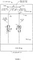
- Figure 1 depicts an example diagram of an electronic map 100 of a field 110.
- Electronic map 100 may be stored in a guidance system 114 and displayed on a computer screen to a vehicle operator.
- the vehicle operator may draw a boundary line 102 on electronic map 100 around field 110 and draw a border line 107 defining a headland area 106.
- the operator also may draw AB lines 108 on electronic map 100 that provide imaginary reference lines over rows in field 110.
- guidance system 114 may include a global navigation satellite system (GNSS) and/or an inertial navigation system (INS) for detecting a position of vehicle 112 on field 110.
- Guidance system 114 may automatically steer vehicle 112 over AB line 108A. Previous guidance systems may go into an idle mode when vehicle 112 reaches an end of AB line 108A. The vehicle operator then may manually perform a keyhole turn 120 turning vehicle 112 around 180 degrees and back onto a next adjacent AB line 108B. The vehicle operator then re-activates the guidance system to automatically steer vehicle 112 over a next adjacent AB line 108B.
- GNSS global navigation satellite system
- INS inertial navigation system
- Guidance system 114 may automatically perform K-turns 130 that turn vehicle 112 around 180 degrees within headland 106 for traversing a next adjacent AB line 108B. K-turns 130 not only prevent the vehicle operator from having to manually turn around vehicle 112 but also reduce the amount of boundary or headland area used in field 110.
- guidance system 114 may automatically steer vehicle 112 along AB line 108C.
- Guidance system 114 may detect vehicle 112 reaching the end of AB line 108C near border 104.
- Guidance system 112 then may steer vehicle 112 through a series of turns referred to as K-turn 130.
- K-turn 130 uses substantially less headland area 106 to maneuver vehicle 111 around 180 degrees and back onto next adjacent AB line 108D.
- the smaller headland area 106 frees up more area of field 110 for growing crops.
- the smaller turning area of K-turn 130 also reduces the likelihood of vehicle 112 colliding with trees and other obstructions that may extend around boundary 102 of field 110.
- Table 1.0 details size comparisons between classical forward keyhole turn 120 and K-Turn 130 maneuvers generated under the same conditions at 15 kilometers (km)/ hour (h). Table 1.0 shows K-turn 130 uses less width and height at almost each swath distance thus reducing the amount of headland area used for vehicle turns.
- the width and height of the K-Turn paths in Table 1.0 may change at different swath distances when the vehicle is steered at different maximum curvatures and curvature rates at the departure and destination positions.
- the K-Turn path planning may use a higher value of maximum curvature (or smaller turn radius) and steering curvature rate (faster steering) for a quicker and shorter turn.
- the K-Turn may have a lower steering curvature and steering rate for a better line acquisition and alignment before the vehicle and implement get back into the field.
- Table 1.0 Comparison between forward keyhole turn and K-turn maneuver.
- Figure 2 shows in more detail one example of K-turn 130 performed by guidance system 114.
- guidance system 114 uses three different maneuvers. As vehicle 112 reaches the end of AB line 108A at border 104, guidance system 114 initiates a first K-turn segment 132A turning vehicle 112 to the right at a first steering curvature, steering curvature rate, speed, and distance to a first position 134A.
- guidance system 114 may try to steer vehicle 112 from position 133 to position 134A as quickly as possible. For example, guidance system 114 may steer vehicle 112 at a maximum steering curvature and steering curvature rate. The maximum steering curvature is the hardest the vehicle can be turned to the left or right and the steering curvature rate is the rate is which the vehicle is turned to the left or right.
- Guidance system 114 then changes vehicle 112 into a reverse gear and moves vehicle 112 in a reverse direction along a second straight (in this example) K-turn segment 132B.
- Guidance system 114 stops vehicle 112 after reaching a second position 134B.
- Guidance system 114 then changes vehicle 112 back into a forward gear and maneuvers vehicle 112 in a forward right turn direction along a third K-turn segment 132C with a second curvature.
- the curvature, curvature rate and length of segments 132A and 132C are symmetric. However, to further reduce the height or width of K-turn 130, the curvature, curvature rate and length of one of turn segments 132A or 132C may be different to the other.
- guidance system 114 may transition back into a field processing mode and steer vehicle 112 along AB line 108B.
- Guidance system 114 may perform a similar K-turn 130 when vehicle 112 reaches an opposite end of field 110.
- Segments 132 of K-turn 130 may be straight lines or continuous-curvature planar curves bounded by the maximum steering curvature of vehicle 112 and a curvature first derivative bounded by a maximum steering curvature rate of vehicle 112.
- Guidance system 114 may use a higher value of curvature and curvature rate for first two turn segments 132A and 132B and a lower value for third turn segment 132C to more quickly place an implement towed by vehicle 112 back on AB line 108B.
- the vehicle operator may manually initiate K-turn 130, or guidance system 114 may automatically initiate K-turn 130, when vehicle 112 reaches border 104.
- vehicle 112 may be traveling at 2 meters/second and guidance system 114 may include a timer set at 50 seconds. If not fully automated, guidance system 114 may display an option to the vehicle operator to enable the automatic K-turn 130 when vehicle 112 comes within 100 meters of headland 106.
- Guidance system 114 may keep offering the K-turn on a computer screen until the K-turn can no longer be performed within headland area 106.
- guidance system 114 may complete first turn segment 132A and allow the vehicle operator to shift the vehicle into a reverse gear. Guidance system 114 then may automatically move vehicle 112 along second turn segment 132B, etc. Alternatively, the entire process, or any portion, of initiating K-turn 130 at the end of AB line 130A, executing turn segments 132A-132C, and steering vehicle 112 back over next AB line 108B may be automatically performed by guidance system 114.
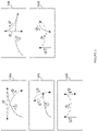
- guidance system 112 may use different combinations of K-turn segments for K-turn 130.
- guidance system 114 may use any of the following segment combinations to derive K-turn 130:
- guidance system 114 may use K-Turns including:
- Guidance system 114 may automatically select different K-turns 130A-130E based on different environmental conditions including the orientation of vehicle 112 and the contour of field 110, number of skipped rows/way-lines 108, limits on the size of headland area 106, and other conditions specific to field applications.
- AB lines 108 may end on a left sloping hill promoting a first left curve segment, a second reverse curve segment, and a third left curve segment.
- guidance system 114 may select one of K-turns 130A-130E using the least amount of overall headland area 106, smallest width, and/or smallest height.
- guidance system 114 may select one of K-turns 130A-130E that uses a least amount of space left of a current AB line 108A or the least amount of space right of the current AB line 108A.
- K-Turn path 130E with first and last straight segments may be better for a parallel field with a trailed implement because it allows for full field coverage without extending outside of the headland area.
- one of K-turns 130A-130E may be easier or more efficient to perform on a contoured headland 106 or a headland with a particular soil condition.
- straight reverse second segments may be easier to execute on flat headland areas 106.
- a tree or other obstruction overhanging or lying within headland 106 may favor one of K-turns 130A-130E that avoids the obstruction.
- K-turn 130A as depicted in Figure 2 is an example of a curve-straight-curve segment combination.
- First curve segment 132A and last curve segment 132C of K-turn 130A are generally made up of three basic geometries:
- the k and k max values are the steering curvature and the maximum steering curvature, respectively of the vehicle.
- Steering curvature is the reciprocal of the turning radius of the vehicle to one direction.
- the unit of steering curvature is 1/m.
- the value of k max in general can be different when steering to the left and to the right.
- the values ⁇ and ⁇ max are the steering curvature rate and the maximum steering curvature rate, respectively, of the vehicle and indicate how fast the vehicle can be turned to the left or right.
- the unit of steering curvature rate is 1/m 2 .
- the sign convention for steering curvature and steering curvature rate is usually accepted to be positive to the right and negative to the left.
- a clothoid is a curve whose curvature changes linearly with a constant rate with its curve length.
- the path that a vehicle usually takes steering from straight to full lock on one direction is an example of a clothoid.
- K-Turn path planning uses clothoid arcs from maximum steering curvature and curvature rate of a vehicle to generate curve segments that are both smooth and fully drivable for the vehicle to steer.
- the circular arc in item 2 in many cases might have a zero length and the turn segment then may be two clothoids joined together.
- Guidance system 114 may use k max and ⁇ max of vehicle 112 to achieve the shortest possible path length for K-turn 130.
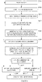
- Figure 4 shows one example of how the guidance system derives a K-turn path for automatically turning around a vehicle.
- the K-turn path generation runs in idle state waiting for a start command.
- the guidance system starts generating the next K-turn values for turning around the vehicle and continuing on a next adjacent AB line.
- guidance system 114 may pre-calculate the K-turns based on terrain information, map AB line directions, and headland dimensions identified in the electronic map shown in Figures 1 and 2 .
- the vehicle operator may initiate K-turn generation by selecting an icon on a guidance system display screen that directs the guidance system to calculate the next K-turn or series of K-turns.
- the guidance system may automatically start K-turn generation 200B based on vehicle 112 reaching border 104 of field 110 ( Figure 2 ).
- the guidance system reads vehicle steering capabilities from memory.
- the guidance system 114 may calculate and store the following vehicle steering parameters or may store the following pre-derived steering parameters:
- the operator or the guidance system may turn the steering wheel of the vehicle as far as possible to the left and then as far as possible to the right at a highest possible steering speed.
- the guidance system may measure the maximum left and right steering curvature (or minimum turning radii).
- the guidance system then may calculate the maximum steering curvature rate of the vehicle by measuring how fast the steering curvature changes.
- the guidance system may use the GPS receivers and inertial navigation devices to measure the vehicle maximum left and right steering curvature and curvature rate.
- the guidance system calculates the departure and destination postures of the vehicle. For example, the guidance system determines the position and heading of the vehicle at the end of the current AB line (departure posture) and desired position and heading of the vehicle at the beginning of the next AB line (destination posture). The guidance system may determine the departure posture from the GNSS and/or inertial navigation system (INS) data.
- INS inertial navigation system
- the guidance system may determine the destination posture based on the location and direction of the next target AB way-line. For example, the guidance system may calculate the destination posture at the starting point of the next AB way-line and the destination heading as 180 degrees from the current vehicle heading. This depends on the shape at each AB way-line of the field.
- the guidance system may generate the K-turn with a starting direction as a relative direction from the departure posture to the destination posture. For example, if the next AB way-line in the field is to the right of the current AB way-line, the guidance system may calculate the K-turn with a starting right turn.
- the guidance system may report success in operation 200I if a K-turn path generated in operation 200E satisfies certain success criterion in operation 200F.
- the success criteria may include the K-turn joining the departing and the destination postures, the entire K-turn with all three segments remaining within the headland, and the K-turn having a smallest overall length.
- the guidance system in operation 200G retries the K-turn generation with the starting direction opposite to the relative direction from departure to destination postures. For example, for a long skipping distance between departure and destination swaths when turning to the right hand side direction, the guidance system may generate a curve-straight-curve K-turn combination with left turns for the first and third segments. An initial curve segment to the right, a second straight reverse segment, and a third curve segment to the right are shown in Figure 2 . However, to reduce the distance of the K-turn to the right, the guidance system may start with a first curve segment to the left, a second straight segment in a reverse direction to right, and the third curve segment to the left to the next AB way-line.
- the guidance system reports success in operation 200I if the second K-turn generation meets the success criterion. If not, the guidance system reports a K-turn generation error and notifies the vehicle operator in operation 200J. In operation 200K, the guidance system completes K-turn generation and returns to running in idle state in operation 200A. If no K-turn can be successfully generated within the headland area, the operator may have to manually perform a manoeuver.
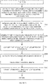
- Figures 5A and 5B show in more detail how a K-turn is generated.
- the guidance system again runs K-Turn generation in idle state and waiting for a start command.
- the guidance system starts calculating K-turns for turning around the vehicle and continuing on a next adjacent AB line.
- Operation 205C reads the vehicle steering and speed capabilities as mentioned above in Figure 4 .
- the guidance system may select a K-turn shape for generation. For example, the guidance system may automatically select a first one of K-turn shapes 130 in Figure 3 . In one example, the guidance system may first select K-turn shape 130E for a flat field with substantially straight parallel rows or may first select K-turn 130C or 130D for a contoured field with curved rows. As also mentioned above, the vehicle operator may manually select or program which K-turn shapes to use for calculation and in what order.
- operation 205E determines the departure and destination postures based on the number of skipped rows and turn direction.
- the departure and destination postures may vary based on the shape of the AB way-lines, the spacing between the current and next AB way-line, and the selected first turn direction of the K-turn.
- Operation 205F calculates the available headland space for the next K-turn. For example, different amounts of headland space may be available forward, to the left, and to the right based on the location of the current AB way-line and the next AB way-line.
- Operation 205G calculates the posture of the vehicle for the start of the second turn segment and operation 205H calculates the posture of the vehicle for the start of the third turn segment. For example, based on the selected K-turn, the start of the second and third segments may be in one of the different headings and locations shown in Figure 3 .
- Operation 2051 may calculate the first K-turn segment from the departure posture at the end of the current AB way-line to the start of the second turn segment.
- the path shape and length are based on the selected K-turn, vehicle speed, maximum steering curvature, and steering curvature rate.
- Operation 205J calculates the second K-turn segment from the start of the second turn segment to the start of the third K-turn segment.
- Operation 205K calculates the third K-turn segment from the start of the third turn segment to the start of the next AB way-line.
- Operation 205L combines the three calculated segments together for the selected K-turn shape and operation 205M determines if any part of the K-turn path extends outside of the available headland space.
- Operation 205N calculates the overall K-turn path length and/or the height and width of the K-turn shape. Operation 205O then stores the calculated K-turn length and status for possible comparison with other K-turn shapes. For example, the navigation system may produce a report used in Figure 4 to determine which K-turn shape has the shortest overall length and remain within the available headland area. As explained above, the navigation system may select the K-turn shape with the shortest overall length that can be performed most quickly within the available headland area.
- Figure 6 shows how the guidance system uses the derived K-turn path to turn the vehicle around onto a next AB way-line.
- a typical scenario of executing the K-turn may include the vehicle operator creating a boundary or headland region around the perimeter of a field as described above in Figures 1 and 2 .
- the vehicle operator may define reference AB way-lines for the field up to the boundary adjacent to the headland region.
- the operator also may select or enable K-turn operations via a menu option.
- the guidance system in operation 210A may run in idle state and wait for a command to start steering the vehicle on a K-Turn path.
- the guidance system in operation 210B may start the sequence of operations to perform a K-turn to move the vehicle from the end of the current AB way-line to the next AB way-line.
- the guidance system sends the first K-turn segment to a vehicle steering controller.
- the vehicle controller may be any type of electro-mechanical system that steers the vehicle along the first K-turn segment.
- the guidance system may send a series of turn and speed commands that the vehicle steering controller uses to steer the vehicle along the first K-turn segment in operation 210D.
- Operation 210E monitors the vehicle location and operation 210F slows down the vehicle to a stationary in forward direction when the vehicle reaches the end of the first K-turn segment. Operation 210G then shifts gears in the vehicle from the forward direction to a reverse direction.
- the guidance system in operation 210H sends the second K-turn segment to the steering controller.
- the guidance system may send steering commands for a straight reverse direction at a specified distance.
- One example scheme for automatically steering a vehicle in both curved or straight paths in either a forward or reverse direction is described in co-pending U.S. Patent Application Ser. No. 15/345,792 entitled: SINGLE-MODE IMPLEMENT STEERING, filed November 8, 2016.
- Operation 210I steers the vehicle along the second K-turn segment and operation 210K slows down the vehicle to a stationary in reverse direction when the vehicle reaches the end of the second K-turn segment. Operation 210L then changes gears of the vehicle from the reverse direction back to the forward direction.
- the guidance system in operation 210M sends the third K-turn segment to the vehicle steering controller.
- the guidance system may send steering commands for a forward right curve at the specified speed, maximum steering curvature, and steering curvature rate.
- Operation 210N then steers the vehicle along the third K-turn segment.
- Operation 210O detects the vehicle reaching the end of the third segment and operation 210P sends the destination path to the vehicle steering controller.
- the guidance system may send steering commands for the next AB way-line.
- operation 210Q transitions into steering the vehicle along the next AB way-line.
- GNSS Global navigation satellite system
- GPS U.S.
- Galileo European Union, proposed
- GLONASS Russian
- Beidou China
- Compass China
- IRNSS India, proposed
- QZSS Japan, proposed
- other current and future positioning technology using signal from satellites, with or without augmentation from terrestrial sources.
- Inertial navigation systems may include gyroscopic (gyro) sensors, accelerometers and similar technologies for providing outputs corresponding to the inertial of moving components in all possible axes (linear directions along and rotational about the X, Y and Z axes respectively). Said terminology will include the words specifically mentioned, derivative thereof and words of similar meaning.
- Figure 7 generally designates guidance system 114 implementing an electrical direct-drive steering assistance mechanism 3.
- a GNSS receiver 4 and a guidance processor 6 are connected to a GNSS antenna 12 and installed into vehicle 112, such as an agricultural vehicle or tractor.
- An auto-steering system 8 is electrically connected to guidance processor 6, and is mechanically interfaced with vehicle 112 via steering assistance mechanism 3.
- FIG. 8 shows an additional detail of guidance system 114.
- the GNSS receiver 4 is further comprised of an RF convertor (i.e., down convertor) 16, a tracking device 18, and a rover RTK receiver element 20.
- the receiver electrically communicates with, and provides GNSS positioning data to, guidance processor 6.
- Guidance processor 6 includes a graphical user interface (GUI) 26, a microprocessor 24, and a media element 22, such as a memory storage drive.
- Guidance processor 6 electrically communicates with, and provides control data to auto-steering system 8.
- An auto-steering subsystem includes a wheel movement detection switch 28 and an encoder 30 for interpreting guidance and steering commands from CPU 6.
- Auto-steering system 8 may interface mechanically with the vehicle's steering column 34, which is mechanically attached to steering wheel 32.
- a control line 42 may transmit guidance data from the CPU 6 to the auto-steering system 8.
- An electrical subsystem 44 which powers the electrical needs of vehicle 112, may interface directly with auto-steering system 8 through a power cable 46.
- Auto-steering subsystem 8 can be mounted to steering column 34 near the floor of the vehicle, and in proximity to the vehicle's control pedals 36. Alternatively, auto-steering system 8 can be mounted at other locations along steering column 34.
- the auto-steering system 8 physically drives and steers vehicle 112 by actively turning steering wheel 32 via steering column 34.
- a motor 45 powered by vehicle electrical subsystem 44 may power a worm drive which powers a worm gear affixed to auto-steering system 8.
- auto-steering system 8 is integrated directly into the vehicle drive control system independently of steering column 34.
- Computer-readable storage medium (or alternatively, “machine-readable storage medium”) used in guidance system 114 may include any type of memory, as well as new technologies that may arise in the future, as long as they may be capable of storing digital information in the nature of a computer program or other data, at least temporarily, in such a manner that the stored information may be "read” by an appropriate processing device.
- the term “computer-readable” may not be limited to the historical usage of “computer” to imply a complete mainframe, mini-computer, desktop, wireless device, or even a laptop computer. Rather, “computer-readable” may comprise storage medium that may be readable by a processor, processing device, or any computing system. Such media may be any available media that may be locally and/or remotely accessible by a computer or processor, and may include volatile and non-volatile media, and removable and non-removable media.
- the present invention further comprises a computer readable storage medium which stores program instructions allowing a computer or a processor to execute the operations disclosed in the present description and/or in the attached computer program product claims.
Landscapes
- Engineering & Computer Science (AREA)
- Mechanical Engineering (AREA)
- Life Sciences & Earth Sciences (AREA)
- Combustion & Propulsion (AREA)
- Transportation (AREA)
- Chemical & Material Sciences (AREA)
- Physics & Mathematics (AREA)
- Environmental Sciences (AREA)
- Soil Sciences (AREA)
- Mathematical Physics (AREA)
- Radar, Positioning & Navigation (AREA)
- Remote Sensing (AREA)
- Automation & Control Theory (AREA)
- Aviation & Aerospace Engineering (AREA)
- General Physics & Mathematics (AREA)
- Navigation (AREA)
- Steering Control In Accordance With Driving Conditions (AREA)
- Traffic Control Systems (AREA)
Claims (14)
- Steuereinrichtung zum Lenken eines Fahrzeugs (112), die aufweist:
einen Hardware-Prozessor, um:das Fahrzeug (112) entlang einer ersten Weglinie (108A-D) auf einem Feld (110) zu lenken;zu erfassen, dass das Fahrzeug (112) ein Ende der ersten Weglinie (108A-D) erreicht;einen K-Wende-Pfad (130A-E) für das Fahrzeug (112) aus unterschiedlichen K-Wende-Pfaden (130A-E) abzuleiten, und zwar beruhend auf Grenzen einer Erstreckung eines Randbereichs (106);den K-Wende-Pfad (130A-E) an eine Lenk-Steuereinrichtung zu senden, um das Fahrzeug (112) im Randbereich (106) des Feldes (110) auf einen Anfang einer zweiten Weglinie (108A-D) auf dem Feld (110) zu wenden; unddas Fahrzeug (112) entlang der zweiten Weglinie (108A-D) lenken. - Steuereinrichtung nach Anspruch 1, wobei der Hardware-Prozessor ferner eingerichtet ist, um:ein erstes Segment (132A) des K-Wende-Pfades (130A-E) an die Lenk-Steuereinrichtung zu senden, um das Fahrzeug (112) in Vorwärtsrichtung zu lenken;zu erfassen, dass das Fahrzeug (112) ein Ende des ersten Segments (132A) erreicht;ein zweites Segment (132B) des K-Wende-Pfades (130A-E) an die Lenk-Steuereinrichtung zu senden, um das Fahrzeug (112) in Rückwärtsrichtung zu lenken;zu erfassen, dass das Fahrzeug (112) ein Ende des zweiten Segments (132B) erreicht; undein drittes Segment (132C) des K-Wende-Pfades (130A-E) an die Lenk-Steuereinrichtung zu senden, um das Fahrzeug (112) weiter zur Ziel-Weglinie (108A-D) zu lenken.
- Steuereinrichtung nach Anspruch 2,wobei:das erste Segment (132A) die Lenk-Steuereinrichtung veranlasst, einen Wendezug des Fahrzeugs (112) in Vorwärtsrichtung mit einer ersten Krümmung und Krümmungsrate durchzuführen;das zweite Segment (132B) die Lenk-Steuereinrichtung veranlasst, einen Wendezug des Fahrzeugs (112) in Rückwärtsrichtung mit einer zweiten Krümmung und Krümmungsrate durchzuführen;das dritte Segment (132C) die Lenk-Steuereinrichtung veranlasst, einen Wendezug des Fahrzeugs (112) in Vorwärtsrichtung mit einer dritten Krümmung und Krümmungsrate durchzuführen;und/oderwobei das erste und das dritte Segment (132A, 132C) ungefähr symmetrisch sind.
- Steuereinrichtung nach einem der Ansprüche 1-3,wobei der Hardware-Prozessor ferner eingerichtet ist, um:eine maximale Lenkkrümmung des Fahrzeugs (112) zu ermitteln; undmindestens eines des ersten, zweiten und dritten Segments (132A-C) beruhend auf der maximalen Lenkkrümmung zu berechnen; undwobei in einigen Ausführungsformen der Hardware-Prozessor ferner eingerichtet ist, um:eine Lenkkrümmungsrate des Fahrzeugs (112) zu ermitteln; undmindestens eines des ersten, zweiten und dritten Segments (132A-C) beruhend auf der Lenkkrümmungsrate zu berechnen.
- Steuereinrichtung nach einem der Ansprüche 1-4, wobei der Hardware-Prozessor ferner eingerichtet ist, um:einen ersten K-Wende-Pfad (130A-E) mit einer ersten Wenderichtung zu berechnen;den ersten K-Wende-Pfad (130A-E) an die Lenk-Steuereinrichtung zum Lenken des Fahrzeugs (112) zu senden, wenn der erste K-Wende-Pfad (130A-E) innerhalb eines Randbereichs (106) des Feldes (110) verbleibt;einen zweiten K-Wende-Pfad (130A-E) mit einer zweiten Wenderichtung zu berechnen, wenn sich ein Teil des ersten K-Wende-Pfades (130A-E) außerhalb des Randbereichs (106) des Feldes (110) erstreckt; undden zweiten K-Wende-Pfad (130A-E) an die Lenk-Steuereinrichtung zum Lenken des Fahrzeugs (112) zu senden, wenn der zweite K-Wende-Pfad (130A-E) innerhalb des Randbereichs (106) verbleibt.
- Steuereinrichtung nach einem der Ansprüche 1-5,wobei der Hardware-Prozessor ferner eingerichtet ist, um:unterschiedliche K-Wende-Formen zu speichern;einen Ort und eine Ausrichtung des Fahrzeugs (112) am Ende der ersten Weglinie (108A-D) und einen gewünschten Ort und eine gewünschte Ausrichtung des Fahrzeugs (112) am Anfang der zweiten Weglinie (108A-D) zu ermitteln; undeine der unterschiedlichen K-Wende-Formen für den K-Wende-Pfad (130A-E) auszuwählen, und zwar beruhend auf dem Ort und der Ausrichtung des Fahrzeugs (112) am Ende der ersten Weglinie (108A-D) und dem gewünschten Ort und der gewünschten Ausrichtung des Fahrzeugs (112) am Anfang der zweiten Weglinie (108A-D); undwobei in einigen Ausführungsformen der Hardware-Prozessor ferner eingerichtet ist, um:die Form des Feldes (110) am Ende der ersten Weglinie (108A-D) und am Anfang der zweiten Weglinie (108A-D) zu ermitteln; undeine der unterschiedlichen K-Wende-Formen auszuwählen, und zwar beruhend auf der Form des Feldes (110) am Ende der ersten Weglinie (108A-D) und am Anfang der zweiten Weglinie (108A-D).
- Steuereinrichtung nach einem der Ansprüche 1-6, wobei der Hardware-Prozessor ferner eingerichtet ist, um:das Feld (110) auf einer elektronischen Karte (100) anzuzeigen;eine Grenze (102), die das Feld (110) umgibt, auf der elektronischen Karte (100) anzuzeigen;den Randbereich (106) auf der elektronischen Karte (100) zwischen der Grenze (102) und einem Ende des Feldes (110) zu definieren; undden K-Wende-Pfad (130A-E) beruhend auf dem auf der elektronischen Karte (100) definierten Randbereich (106) abzuleiten.
- Verfahren zum Ableiten eines K-Wende-Pfades (130A-E), das umfasst:Ermitteln einer maximalen Lenkkrümmung eines Fahrzeugs (112);Ermitteln einer maximalen Lenkkrümmungsrate des Fahrzeugs (112);Ermitteln einer Startposition und -orientierung des Fahrzeugs (112);Ermitteln einer Endposition und -orientierung des Fahrzeugs (112);Ableiten von K-Wende-Segmenten (132A-C) beruhend auf der Lenkkrümmung, der Lenkkrümmungsrate, der Startposition und -orientierung des Fahrzeugs (112) und der Endposition und -orientierung des Fahrzeugs (112); undSenden der K-Wende-Segmente (132A-C) an eine Lenk-Steuereinrichtung zum Lenken des Fahrzeugs (112);ferner umfassend:Speichern unterschiedlicher K-Wende-Formen;Ermitteln eines verfügbaren Randbereichs (106) beruhend auf der Startposition und -orientierung des Fahrzeugs (112) und der Endposition und -orientierung des Fahrzeugs (112);Auswählen einer der unterschiedlichen K-Wende-Formen beruhend auf dem verfügbaren Randbereich (106); undSenden der K-Wende-Segmente (132A-C) für die ausgewählte eine K-Wende-Form der K-Wende-Formen an die Lenk-Steuereinrichtung zum Lenken des Fahrzeugs (112).
- Verfahren nach Anspruch 8, ferner umfassend:Verwenden einer ersten Startrichtung relativ von der Startposition und -orientierung zu der Endposition und -orientierung, um einen ersten Satz der K-Wende-Segmente (132A-C) zu berechnen;Senden des ersten Satzes von K-Wende-Segmenten (132A-C) an die Lenk-Steuereinrichtung zum Wenden des Fahrzeugs (112), wenn der erste Satz von K-Wende-Segmenten (132A-C) innerhalb eines Randbereichs (106) verbleibt;Verwenden einer zweiten Startrichtung, die der ersten Startrichtung entgegengesetzt ist, um einen zweiten Satz von K-Wende-Segmenten (132A-C) zu berechnen, wenn sich der erste Satz von K-Wende-Segmenten (132A-C) außerhalb des Randbereichs (106) erstreckt; undSenden des zweiten Satzes von K-Wende-Segmenten (132A-C) an die Lenk-Steuereinrichtung zum Wenden des Fahrzeugs (112), wenn der zweite Satz von K-Wende-Segmenten (132A-C) innerhalb des Randbereichs (106) verbleibt.
- Verfahren nach Anspruch 8 oder Anspruch 9,ferner umfassend:Lenken des Fahrzeugs (112) entlang einer ersten Weglinie (108A-D) auf einem Feld (110);Erfassen, dass das Fahrzeug (112) das Ende der ersten Weglinie (108A-D) erreicht;Ableiten der K-Wende-Segmente (132A-C) beruhend auf der Startposition und -orientierung des Fahrzeugs (112) am Ende der ersten Weglinie (108A-D) und einem Abstand zur Endposition und -orientierung des Fahrzeugs (112) am Anfang einer zweiten Weglinie (108A-D);Senden der K-Wende-Segmente (132A-C) an die Lenk-Steuereinrichtung, um das Fahrzeug (112) in die Endposition und -orientierung am Anfang der zweiten Weglinie (108A-D) zu wenden; undLenken des Fahrzeugs (112) auf dem Feld (110) entlang der zweiten Weglinie (108A-D);und/oderferner umfassend:Senden eines ersten K-Wende-Segments (132A) an die Lenk-Steuereinrichtung, um einen Wendezug des Fahrzeugs (112) in Vorwärtsrichtung auszuführen;Erfassen, dass das Fahrzeug (112) ein Ende des ersten der K-Wende-Segmente (132A) erreicht;Senden eines zweiten K-Wende-Segments (132B) an die Lenk-Steuereinrichtung, um einen Wendezug des Fahrzeugs (112) entlang eines zweiten Pfades in einer Rückwärtsrichtung auszuführen;Erfassen, dass das Fahrzeug (112) ein Ende des zweiten der K-Wende-Segmente (132B) erreicht; undSenden eines dritten K-Wende-Segments (132C) an die Lenk-Steuereinrichtung, um einen Wendezug des Fahrzeugs (112) entlang eines dritten Pfades in die Vorwärtsrichtung zu der Endposition und -orientierung auszuführen.
- Verfahren nach einem der Ansprüche 8-10, ferner umfassend:Ermitteln einer maximalen Lenkkrümmung des Fahrzeugs (112) in eine linke Richtung;Ermitteln einer maximalen Lenkkrümmung des Fahrzeugs (112) in eine rechte Richtung;Ermitteln einer maximalen Lenkkrümmungsrate des Fahrzeugs (112) in die linke Richtung;Ermitteln einer maximalen Lenkkrümmungsrate des Fahrzeugs (112) in die rechte Richtung; undVerwenden der maximalen Lenkkrümmung des Fahrzeugs (112) in die linke Richtung, der maximalen Lenkkrümmung des Fahrzeugs (112) in die rechte Richtung, der maximalen Lenkkrümmungsrate des Fahrzeugs (112) in die linke Richtung und der maximalen Lenkkrümmungsrate des Fahrzeugs (112) in die rechte Richtung, um die K-Wende-Segmente (132A-C) abzuleiten.
- Verfahren nach einem der Ansprüche 8-11.ferner umfassend:Senden eines ersten K-Wende-Segments (132A) an die Lenk-Steuereinrichtung, wodurch bewirkt wird, dass das Fahrzeug (112) einen Wendezug mit einer ersten Krümmung und ersten Krümmungsrate ausführt;Senden eines zweiten K-Wende-Segments (132B) an die Lenk-Steuereinrichtung, wodurch bewirkt wird, dass das Fahrzeug (112) einen Wendezug mit einer zweiten Krümmung und zweiten Krümmungsrate ausführt; undSenden eines dritten K-Wende-Segments (132C) an die Lenk-Steuereinrichtung, wodurch bewirkt wird, dass das Fahrzeug (112) einen Wendezug mit einer dritten Krümmung und dritten Krümmungsrate ausführt;wobei in einigen Ausführungsformen die erste Krümmung und Krümmungsrate und die dritte Krümmung und Krümmungsrate gleich sind.
- Computerprogrammprodukt zum Steuern eines Fahrzeugs (112), wobei das Computerprogrammprodukt einen Satz von Anweisungen umfasst, die verwendbar sind, um:ein erstes Wendesegment (132A) zu erzeugen, das das Fahrzeug (112) veranlasst, sich in Vorwärtsrichtung von einer aktuellen Position bei einer ersten Weglinie (108A-D) in einem Feld (110) zu einer ersten Position außerhalb des Feldes zu bewegen (110);ein zweites Wendesegment (132B) zu erzeugen, das das Fahrzeug (112) veranlasst, sich in Rückwärtsrichtung von einem Ende des ersten Wendesegments (132A) zu einer zweiten Position außerhalb des Feldes (110) zu bewegen; undein drittes Wendesegment (132C) zu erzeugen, das das Fahrzeug (112) veranlasst, sich in Vorwärtsrichtung von einem Ende des zweiten Wendesegments (132B) zu einer gewünschten Position bei einer zweiten Weglinie (108A-D) auf dem Feld zu bewegen (110);wobei das erste, das zweite und das dritte Wendesegment (132A-C) einen K-Wende-Pfad (130A-E) bilden, der aus unterschiedlichen K-Wende-Pfaden (130A-E) abgeleitet ist, und zwar beruhend auf Grenzen einer Erstreckung eines Randbereichs (106), in dem das Fahrzeug (112) gewendet werden soll.
- Computerprogrammprodukt nach Anspruch 13,wobei die Anweisungen ferner verwendbar sind, um mindestens eines des ersten, zweiten oder dritten Wendesegments (132A-C) mit einer durch eine maximale Lenckrümmung des Fahrzeugs (112) begrenzten Krümmung und einer durch eine maximale Lenkkrümmungsrate des Fahrzeugs (112) begrenzten ersten Ableitung der Krümmung zu erzeugen;
und/oderwobei die Anweisungen ferner verwendbar sind, um:das Feld (110) auf einer elektronischen Karte (100) anzuzeigen;eine Grenze (102), die das Feld (110) umgibt, auf der elektronischen Karte (100) anzuzeigen;den Randbereich (106) auf der elektronischen Karte (100) zwischen der Grenze (102) und einem Ende des Feldes (110) zu definieren; unddas erste, zweite und dritte Wendesegment (132A) beruhend auf dem definierten Randbereich (106) auf der elektronischen Karte (100) abzuleiten.
Applications Claiming Priority (2)
| Application Number | Priority Date | Filing Date | Title |
|---|---|---|---|
| US201562257398P | 2015-11-19 | 2015-11-19 | |
| US15/348,072 US10266201B2 (en) | 2015-11-19 | 2016-11-10 | K-turn path controller |
Publications (3)
| Publication Number | Publication Date |
|---|---|
| EP3170381A1 EP3170381A1 (de) | 2017-05-24 |
| EP3170381B1 EP3170381B1 (de) | 2019-07-17 |
| EP3170381B2 true EP3170381B2 (de) | 2022-09-14 |
Family
ID=57354210
Family Applications (1)
| Application Number | Title | Priority Date | Filing Date |
|---|---|---|---|
| EP16199556.8A Active EP3170381B2 (de) | 2015-11-19 | 2016-11-18 | Kehrtwende-steuergerät |
Country Status (4)
| Country | Link |
|---|---|
| US (1) | US10266201B2 (de) |
| EP (1) | EP3170381B2 (de) |
| AU (2) | AU2016259279B2 (de) |
| CA (1) | CA2948304C (de) |
Families Citing this family (66)
| Publication number | Priority date | Publication date | Assignee | Title |
|---|---|---|---|---|
| US10266201B2 (en) * | 2015-11-19 | 2019-04-23 | Agjunction Llc | K-turn path controller |
| EP3298873B1 (de) * | 2016-09-21 | 2020-03-04 | Exel Industries | Steuerungsvorrichtung für ein fahrzeug, entsprechendes fahrzeug und verfahren |
| US11185006B2 (en) * | 2016-09-29 | 2021-11-30 | Agro Intelligence Aps | System and a method for determining a trajectory to be followed by an agricultural work vehicle |
| US10663966B2 (en) * | 2017-03-29 | 2020-05-26 | Mitsubishi Electric Research Laboratories, Inc. | Vehicle motion control system and method |
| JP6766006B2 (ja) * | 2017-04-26 | 2020-10-07 | 株式会社クボタ | 自動操舵システム |
| US11269346B2 (en) | 2017-06-22 | 2022-03-08 | Agjunction Llc | 3-d image system for vehicle control |
| CN107089458B (zh) * | 2017-07-03 | 2023-03-31 | 成都大学 | 一种新型的智能环保垃圾自动回收系统 |
| KR102709145B1 (ko) * | 2017-12-05 | 2024-09-25 | 가부시끼 가이샤 구보다 | 주행 작업기 |
| US20190353483A1 (en) * | 2018-05-15 | 2019-11-21 | Deere & Company | Coverage-based system and method of planning a turn path for a vehicle |
| JP7109300B2 (ja) * | 2018-07-31 | 2022-07-29 | 株式会社クボタ | 収穫機 |
| US11042162B2 (en) * | 2018-09-13 | 2021-06-22 | Cnh Industrial Canada, Ltd. | System and method for determining work routes for agricultural vehicles |
| KR20200037738A (ko) * | 2018-09-28 | 2020-04-09 | 바이두닷컴 타임즈 테크놀로지(베이징) 컴퍼니 리미티드 | 자율 주행 차량을 위한 나선형 경로 기반의 삼중 포인트 회전 계획 |
| JP7009490B2 (ja) * | 2018-09-28 | 2022-01-25 | バイドゥ ドットコム タイムス テクノロジー (ベイジン) カンパニー リミテッド | 自動運転車両のための制御主導型の3ポイントターン計画 |
| US11459726B2 (en) | 2018-11-29 | 2022-10-04 | Caterpillar Inc. | Control system for a grading machine |
| US11505913B2 (en) | 2018-11-29 | 2022-11-22 | Caterpillar Inc. | Control system for a grading machine |
| US11459725B2 (en) | 2018-11-29 | 2022-10-04 | Caterpillar Inc. | Control system for a grading machine |
| US11466427B2 (en) | 2018-11-29 | 2022-10-11 | Caterpillar Inc. | Control system for a grading machine |
| US11486113B2 (en) * | 2018-11-29 | 2022-11-01 | Caterpillar Inc. | Control system for a grading machine |
| EP3695694B8 (de) * | 2019-02-14 | 2021-09-08 | Stiga S.P.A. | Robotisches fahrzeug für beweglichen betrieb in einem arbeitsbereich |
| JP7137270B2 (ja) * | 2019-02-28 | 2022-09-14 | ヤンマーパワーテクノロジー株式会社 | 自律走行システム |
| JP7162570B2 (ja) * | 2019-06-24 | 2022-10-28 | 株式会社クボタ | 作業車 |
| JP7132191B2 (ja) * | 2019-08-08 | 2022-09-06 | ヤンマーパワーテクノロジー株式会社 | 作業車両用の自動走行システム |
| JP7151669B2 (ja) * | 2019-08-29 | 2022-10-12 | 井関農機株式会社 | 作業車両 |
| EP4028844B1 (de) | 2019-09-09 | 2024-11-27 | Mtd Products Inc. | Echtzeit-kinematikleistungsgerät mit selbstlenkung |
| US11292454B2 (en) * | 2019-09-19 | 2022-04-05 | GM Global Technology Operations LLC | Apparatus and method that determine parking feasibility |
| JP7316198B2 (ja) * | 2019-11-22 | 2023-07-27 | ヤンマーパワーテクノロジー株式会社 | 作業車両用の自動走行システム |
| US11590977B2 (en) * | 2019-12-31 | 2023-02-28 | Rivian Ip Holdings, Llc | Systems and methods for providing a vehicle with a torque vectored K-turn mode |
| EP3850932B1 (de) * | 2020-01-17 | 2023-10-11 | CNH Industrial Sweden AB | Verfahren zur steuerung eines landwirtschaftlichen pfluges |
| US12077210B2 (en) * | 2020-02-13 | 2024-09-03 | Steering Solutions Ip Holding Corporation | Vehicle steering control system |
| WO2021178998A1 (en) | 2020-03-02 | 2021-09-10 | Raven Industries, Inc. | Guidance systems and methods |
| DE102020109013A1 (de) * | 2020-04-01 | 2021-10-07 | Horsch Leeb Application Systems Gmbh | Verfahren zur Fahrspurplanung mehrerer landwirtschaftlicher Arbeitsmaschinen |
| EP3903556B1 (de) * | 2020-04-30 | 2025-08-13 | PTx Trimble LLC | Verfahren zur wegeplanung für mehrsegmentkurven |
| US11814074B2 (en) * | 2020-04-30 | 2023-11-14 | Trimble Inc. | Headland-following turns |
| US11500390B2 (en) | 2020-04-30 | 2022-11-15 | Trimble Inc. | Multi-segment turns |
| CN111764235B (zh) * | 2020-06-19 | 2022-02-18 | 三一汽车制造有限公司 | 工程机械转弯控制方法、工程机械和计算机设备 |
| JP2022052261A (ja) * | 2020-09-23 | 2022-04-04 | ヤンマーホールディングス株式会社 | 自動走行システム、自動走行方法、及び自動走行プログラム |
| US11809191B2 (en) * | 2020-09-29 | 2023-11-07 | Topcon Positioning Systems, Inc. | Maneuvering system for autonomous wheeled robot for optimally reaching starting point |
| US12082516B2 (en) | 2020-12-28 | 2024-09-10 | Cnh Industrial America Llc | Automatic implement detection and management system |
| JP7272375B2 (ja) * | 2021-01-20 | 2023-05-12 | 井関農機株式会社 | 作業車両 |
| US11967059B2 (en) * | 2021-05-18 | 2024-04-23 | Deere &Company | Methods and apparatus to identify headlands |
| US11860635B2 (en) | 2021-05-24 | 2024-01-02 | Trimble Inc. | Area coverage planner |
| US11874665B2 (en) | 2021-05-24 | 2024-01-16 | Trimble Inc. | Area coverage planner with replenishment planner |
| US11925132B2 (en) * | 2021-06-30 | 2024-03-12 | Deere & Company | Methods, apparatus, and articles of manufacture to generate acquisition paths |
| JP7471261B2 (ja) * | 2021-06-30 | 2024-04-19 | 株式会社クボタ | 作業車および自動走行制御システム |
| CN113406960B (zh) * | 2021-07-08 | 2022-06-21 | 浙江大学 | 一种农用无人车辆地头转向的实时路径规划与控制方法 |
| CN113804212B (zh) * | 2021-08-23 | 2022-07-26 | 上海联适导航技术股份有限公司 | 一种耙地作业的路径规划方法及装置 |
| US12144275B2 (en) | 2021-08-31 | 2024-11-19 | Deere & Company | Methods, apparatus, and articles of manufacture to generate a turn path for a vehicle |
| JP7649723B2 (ja) * | 2021-09-24 | 2025-03-21 | 三菱マヒンドラ農機株式会社 | 作業車両 |
| JP7447881B2 (ja) * | 2021-09-29 | 2024-03-12 | 井関農機株式会社 | 作業車両 |
| JP7695640B2 (ja) * | 2021-10-13 | 2025-06-19 | 井関農機株式会社 | 作業車両 |
| US12085955B2 (en) | 2021-10-19 | 2024-09-10 | Deere & Company | Methods, apparatus, and articles of manufacture to select track paths for one or more vehicles in a field |
| JP7551724B2 (ja) * | 2021-11-04 | 2024-09-17 | 株式会社クボタ | 走行作業機 |
| JP7604359B2 (ja) * | 2021-12-28 | 2024-12-23 | 株式会社クボタ | 農作業支援システム、農業機械、農作業支援装置 |
| JP7631185B2 (ja) * | 2021-12-28 | 2025-02-18 | 株式会社クボタ | 作業車両の支援システム |
| JP7598893B2 (ja) * | 2022-02-15 | 2024-12-12 | ヤンマーホールディングス株式会社 | 経路生成方法、経路生成システム、及び経路生成プログラム |
| EP4514112A1 (de) | 2022-04-29 | 2025-03-05 | Carbon Autonomous Robotic Systems Inc. | System und verfahren zur autonomen feldnavigation |
| US20240138279A1 (en) * | 2022-10-31 | 2024-05-02 | Deere & Company | Field guidance plan template |
| US12530038B2 (en) * | 2022-12-05 | 2026-01-20 | Yanmar Holdings Co., Ltd. | Route creation method, work vehicle, and autonomous travel system |
| JP7782436B2 (ja) * | 2022-12-26 | 2025-12-09 | 井関農機株式会社 | コンバイン |
| US12382861B2 (en) * | 2023-03-30 | 2025-08-12 | Honda Motor Co., Ltd. | Route planning device and route planning method |
| US12314062B2 (en) * | 2023-03-30 | 2025-05-27 | Honda Motor Co., Ltd. | Route data creation device and work machine |
| US12337852B2 (en) * | 2023-06-12 | 2025-06-24 | Ford Global Technologies, Llc | Vehicle load balancing systems and methods |
| US12490664B2 (en) * | 2023-08-02 | 2025-12-09 | Kubota Corporation | Turning control for autonomous agricultural vehicle |
| US12498722B2 (en) * | 2023-08-02 | 2025-12-16 | Kubota Corporation | Turning control for autonomous agricultural vehicle |
| EP4566434A1 (de) * | 2023-12-07 | 2025-06-11 | AGCO International GmbH | System und verfahren zur planung und ausführung einer wende für eine mobile maschine |
| SE547817C2 (en) * | 2024-05-24 | 2025-12-02 | Husqvarna Ab | A robotic lawn mower with enhanced cutting properties in slopes |
Citations (2)
| Publication number | Priority date | Publication date | Assignee | Title |
|---|---|---|---|---|
| EP2020169A2 (de) † | 2007-07-31 | 2009-02-04 | Deere & Company | Verfahren und System zur Erzeugung von Endwindungen |
| EP2583544A1 (de) † | 2011-10-20 | 2013-04-24 | CLAAS Agrosystems KGaA mbH & Co KG. | Visualisierungseinrichtung |
Family Cites Families (35)
| Publication number | Priority date | Publication date | Assignee | Title |
|---|---|---|---|---|
| GB1270257A (en) | 1968-05-03 | 1972-04-12 | Roger Hugh Rutterford | Improvements in or relating to agricultural ploughs |
| US5870303A (en) * | 1987-11-20 | 1999-02-09 | Philips Electronics North America Corporation | Method and apparatus for controlling maneuvers of a vehicle |
| US5663879A (en) | 1987-11-20 | 1997-09-02 | North American Philips Corporation | Method and apparatus for smooth control of a vehicle with automatic recovery for interference |
| US5375059A (en) | 1990-02-05 | 1994-12-20 | Caterpillar Inc. | Vehicle position determination system and method |
| US5194851A (en) | 1991-02-21 | 1993-03-16 | Case Corporation | Steering controller |
| FI942218A0 (fi) | 1994-05-13 | 1994-05-13 | Modulaire Oy | Automatiskt styrningssystem foer obemannat fordon |
| US6070673A (en) | 1996-11-22 | 2000-06-06 | Case Corporation | Location based tractor control |
| US6052647A (en) | 1997-06-20 | 2000-04-18 | Stanford University | Method and system for automatic control of vehicles based on carrier phase differential GPS |
| DE19943410B4 (de) | 1998-09-11 | 2011-08-18 | Honda Giken Kogyo K.K. | Lenksteuersystem für ein Fahrzeug |
| AUPP679598A0 (en) | 1998-10-27 | 1998-11-19 | Agsystems Pty Ltd | A vehicle navigation apparatus |
| US6445983B1 (en) | 2000-07-07 | 2002-09-03 | Case Corporation | Sensor-fusion navigator for automated guidance of off-road vehicles |
| US6377889B1 (en) | 2000-10-13 | 2002-04-23 | Trimble Navigation Limited | Non-linear method of guiding to arbitrary curves with adaptive feedback |
| US6539303B2 (en) | 2000-12-08 | 2003-03-25 | Mcclure John A. | GPS derived swathing guidance system |
| US6819780B2 (en) | 2001-02-02 | 2004-11-16 | Cnh America Llc | Method and apparatus for automatically steering a vehicle in an agricultural field using a plurality of fuzzy logic membership functions |
| AUPR430301A0 (en) | 2001-04-09 | 2001-05-17 | Agsystems Pty Ltd | Soil-cultivation implement control apparatus and method |
| AUPR733701A0 (en) | 2001-08-29 | 2001-09-20 | Beeline Technologies | Apparatus and method for assisted navigation of a land vehicle |
| US6865465B2 (en) | 2002-05-06 | 2005-03-08 | Csi Wireless, Inc. | Method and system for implement steering for agricultural vehicles |
| US7437230B2 (en) | 2003-03-20 | 2008-10-14 | Hemisphere Gps Llc | Satellite based vehicle guidance control in straight and contour modes |
| US7142956B2 (en) | 2004-03-19 | 2006-11-28 | Hemisphere Gps Llc | Automatic steering system and method |
| US8190337B2 (en) | 2003-03-20 | 2012-05-29 | Hemisphere GPS, LLC | Satellite based vehicle guidance control in straight and contour modes |
| US6789014B1 (en) | 2003-05-09 | 2004-09-07 | Deere & Company | Direct modification of DGPS information with inertial measurement data |
| US20060167600A1 (en) | 2005-01-27 | 2006-07-27 | Raven Industries, Inc. | Architecturally partitioned automatic steering system and method |
| US10378896B2 (en) * | 2006-02-27 | 2019-08-13 | Trimble Inc. | Method and system for planning the path of an agricultural vehicle |
| JP5431745B2 (ja) * | 2009-02-13 | 2014-03-05 | マツダ株式会社 | 車両の運動制御装置 |
| US8126620B2 (en) | 2009-04-28 | 2012-02-28 | Cnh America Llc | Grain transfer control system and method |
| US8649930B2 (en) | 2009-09-17 | 2014-02-11 | Agjunction Llc | GNSS integrated multi-sensor control system and method |
| DE102009055059B4 (de) * | 2009-12-21 | 2023-02-02 | Robert Bosch Gmbh | Reduzieren des Lenkmoments bei Bremsmanövern |
| US8589013B2 (en) | 2011-10-25 | 2013-11-19 | Jaybridge Robotics, Inc. | Method and system for dynamically positioning a vehicle relative to another vehicle in motion |
| JP2013228821A (ja) | 2012-04-24 | 2013-11-07 | Mamiya-Op Nequos Co Ltd | 作業機械及びその構成装置、コンピュータプログラム |
| JP6303377B2 (ja) * | 2013-10-04 | 2018-04-04 | アイシン精機株式会社 | 駐車支援装置 |
| JP6170185B2 (ja) * | 2014-02-06 | 2017-07-26 | ヤンマー株式会社 | 作業車両の走行経路の設定方法 |
| JP2015219830A (ja) * | 2014-05-20 | 2015-12-07 | トヨタ自動車株式会社 | 運転支援装置 |
| KR101575296B1 (ko) * | 2014-08-13 | 2015-12-07 | 현대자동차 주식회사 | 선회 단계를 이용한 차량 제어 장치 및 방법 |
| US9522677B2 (en) * | 2014-12-05 | 2016-12-20 | Ford Global Technologies, Llc | Mitigation of input device failure and mode management |
| US10266201B2 (en) * | 2015-11-19 | 2019-04-23 | Agjunction Llc | K-turn path controller |
-
2016
- 2016-11-10 US US15/348,072 patent/US10266201B2/en active Active
- 2016-11-14 AU AU2016259279A patent/AU2016259279B2/en active Active
- 2016-11-14 CA CA2948304A patent/CA2948304C/en active Active
- 2016-11-18 EP EP16199556.8A patent/EP3170381B2/de active Active
-
2021
- 2021-01-21 AU AU2021201523A patent/AU2021201523A1/en not_active Abandoned
Patent Citations (2)
| Publication number | Priority date | Publication date | Assignee | Title |
|---|---|---|---|---|
| EP2020169A2 (de) † | 2007-07-31 | 2009-02-04 | Deere & Company | Verfahren und System zur Erzeugung von Endwindungen |
| EP2583544A1 (de) † | 2011-10-20 | 2013-04-24 | CLAAS Agrosystems KGaA mbH & Co KG. | Visualisierungseinrichtung |
Non-Patent Citations (5)
| Title |
|---|
| M. BERGERMANN ET AL.: "Results with Autonomous Vehicles Operating in Specialty Crops", IEEE INTERNATIONAL CONFERENCE ON ROBOTICS AND AUTOMATION, Saint Paul, Minnesota, pages 1829 - 1835 † |
| M. KISE ET AL.: "Enhancement of Turning Accuracy by Path Planning for Robot Tractor", PROCEEDINGS OF THE 2002 AUTOMATION TECHNOLOGY FOR OFF-ROAD EQUIPMENT CONFERENCE, pages 398 - 404 † |
| R. CARIOU ET AL.: "Maneuvers automation for agricultural vehicle in headland", INTERNATIONAL CONFERENCE ON AGRICULTURAL ENGINEERING, September 2010 (2010-09-01), Clermont- Ferrand , France † |
| R. CARIOU: "Motion planner and lateral-longitudinal controllers for autonomous maneuvers of a farm vehicle in headland", THE 2009 IEEE /RSJ INTERNATIONAL CONFERENCE ON INTELLIGENT ROBOTS AND SYSTEMS, 11 October 2009 (2009-10-11), pages 5782 - 5787 † |
| T. OKSANEN ET AL.: "Path Planning Algorithms for agricultural field machines", HELSINKI UNIVERSITY OF TECHNOLOGY, AUTOMATION TECHNOLOGY LABORATORY, SERIES A: RESEARCH REPORTS, no. 31, December 2007 (2007-12-01), ISBN: 978-951-22-9080-2 † |
Also Published As
| Publication number | Publication date |
|---|---|
| US20170144702A1 (en) | 2017-05-25 |
| AU2021201523A1 (en) | 2021-04-01 |
| CA2948304A1 (en) | 2017-05-19 |
| EP3170381B1 (de) | 2019-07-17 |
| US10266201B2 (en) | 2019-04-23 |
| AU2016259279A1 (en) | 2017-06-08 |
| CA2948304C (en) | 2023-10-10 |
| EP3170381A1 (de) | 2017-05-24 |
| AU2016259279B2 (en) | 2020-10-22 |
Similar Documents
| Publication | Publication Date | Title |
|---|---|---|
| EP3170381B2 (de) | Kehrtwende-steuergerät | |
| USRE48154E1 (en) | System and method for integrating automatic electrical steering with GNSS guidance | |
| US10890922B2 (en) | Automated multi-vehicle alignment steering | |
| US10209714B2 (en) | Line acquisition path generation | |
| CN111771510B (zh) | 对多个区块割刈的方法、系统、机器人及计算机可读介质 | |
| AU2017277800B2 (en) | Swath tracking system for an off-road vehicle | |
| KR102340161B1 (ko) | 병주 작업 시스템 | |
| US7747370B2 (en) | Method for creating end of row turns for agricultural vehicles | |
| EP4037464B1 (de) | Robotisches arbeitswerkzeugsystem und verfahren zum transportieren eines robotischen arbeitswerkzeugsystems zwischen verschiedenen bereichen | |
| US20180321682A1 (en) | Guidance control system for autonomous-traveling vehicle | |
| JP2017531423A5 (de) | ||
| US20250040476A1 (en) | Slope compensation for autonomous lawn mower planner system | |
| JP7045979B2 (ja) | 走行作業機 | |
| DE112021002716T5 (de) | Verfahren zur Positionsbestimmung eines Roboterwerkzeugs, ein Roboterwerkzeug und ein Roboterwerkzeugsystem | |
| JP6851589B2 (ja) | 作業車 | |
| JP7548361B2 (ja) | 作業車両 |
Legal Events
| Date | Code | Title | Description |
|---|---|---|---|
| PUAI | Public reference made under article 153(3) epc to a published international application that has entered the european phase |
Free format text: ORIGINAL CODE: 0009012 |
|
| STAA | Information on the status of an ep patent application or granted ep patent |
Free format text: STATUS: THE APPLICATION HAS BEEN PUBLISHED |
|
| AK | Designated contracting states |
Kind code of ref document: A1 Designated state(s): AL AT BE BG CH CY CZ DE DK EE ES FI FR GB GR HR HU IE IS IT LI LT LU LV MC MK MT NL NO PL PT RO RS SE SI SK SM TR |
|
| AX | Request for extension of the european patent |
Extension state: BA ME |
|
| STAA | Information on the status of an ep patent application or granted ep patent |
Free format text: STATUS: REQUEST FOR EXAMINATION WAS MADE |
|
| 17P | Request for examination filed |
Effective date: 20171124 |
|
| RBV | Designated contracting states (corrected) |
Designated state(s): AL AT BE BG CH CY CZ DE DK EE ES FI FR GB GR HR HU IE IS IT LI LT LU LV MC MK MT NL NO PL PT RO RS SE SI SK SM TR |
|
| STAA | Information on the status of an ep patent application or granted ep patent |
Free format text: STATUS: EXAMINATION IS IN PROGRESS |
|
| 17Q | First examination report despatched |
Effective date: 20180405 |
|
| GRAP | Despatch of communication of intention to grant a patent |
Free format text: ORIGINAL CODE: EPIDOSNIGR1 |
|
| STAA | Information on the status of an ep patent application or granted ep patent |
Free format text: STATUS: GRANT OF PATENT IS INTENDED |
|
| INTG | Intention to grant announced |
Effective date: 20190125 |
|
| GRAS | Grant fee paid |
Free format text: ORIGINAL CODE: EPIDOSNIGR3 |
|
| GRAA | (expected) grant |
Free format text: ORIGINAL CODE: 0009210 |
|
| STAA | Information on the status of an ep patent application or granted ep patent |
Free format text: STATUS: THE PATENT HAS BEEN GRANTED |
|
| RAP1 | Party data changed (applicant data changed or rights of an application transferred) |
Owner name: AGJUNCTION LLC |
|
| AK | Designated contracting states |
Kind code of ref document: B1 Designated state(s): AL AT BE BG CH CY CZ DE DK EE ES FI FR GB GR HR HU IE IS IT LI LT LU LV MC MK MT NL NO PL PT RO RS SE SI SK SM TR |
|
| REG | Reference to a national code |
Ref country code: GB Ref legal event code: FG4D |
|
| REG | Reference to a national code |
Ref country code: CH Ref legal event code: EP |
|
| REG | Reference to a national code |
Ref country code: IE Ref legal event code: FG4D |
|
| REG | Reference to a national code |
Ref country code: DE Ref legal event code: R096 Ref document number: 602016016933 Country of ref document: DE |
|
| REG | Reference to a national code |
Ref country code: AT Ref legal event code: REF Ref document number: 1154962 Country of ref document: AT Kind code of ref document: T Effective date: 20190815 |
|
| REG | Reference to a national code |
Ref country code: NL Ref legal event code: MP Effective date: 20190717 |
|
| REG | Reference to a national code |
Ref country code: LT Ref legal event code: MG4D |
|
| REG | Reference to a national code |
Ref country code: AT Ref legal event code: MK05 Ref document number: 1154962 Country of ref document: AT Kind code of ref document: T Effective date: 20190717 |
|
| PG25 | Lapsed in a contracting state [announced via postgrant information from national office to epo] |
Ref country code: FI Free format text: LAPSE BECAUSE OF FAILURE TO SUBMIT A TRANSLATION OF THE DESCRIPTION OR TO PAY THE FEE WITHIN THE PRESCRIBED TIME-LIMIT Effective date: 20190717 Ref country code: AT Free format text: LAPSE BECAUSE OF FAILURE TO SUBMIT A TRANSLATION OF THE DESCRIPTION OR TO PAY THE FEE WITHIN THE PRESCRIBED TIME-LIMIT Effective date: 20190717 Ref country code: NO Free format text: LAPSE BECAUSE OF FAILURE TO SUBMIT A TRANSLATION OF THE DESCRIPTION OR TO PAY THE FEE WITHIN THE PRESCRIBED TIME-LIMIT Effective date: 20191017 Ref country code: BG Free format text: LAPSE BECAUSE OF FAILURE TO SUBMIT A TRANSLATION OF THE DESCRIPTION OR TO PAY THE FEE WITHIN THE PRESCRIBED TIME-LIMIT Effective date: 20191017 Ref country code: SE Free format text: LAPSE BECAUSE OF FAILURE TO SUBMIT A TRANSLATION OF THE DESCRIPTION OR TO PAY THE FEE WITHIN THE PRESCRIBED TIME-LIMIT Effective date: 20190717 Ref country code: NL Free format text: LAPSE BECAUSE OF FAILURE TO SUBMIT A TRANSLATION OF THE DESCRIPTION OR TO PAY THE FEE WITHIN THE PRESCRIBED TIME-LIMIT Effective date: 20190717 Ref country code: PT Free format text: LAPSE BECAUSE OF FAILURE TO SUBMIT A TRANSLATION OF THE DESCRIPTION OR TO PAY THE FEE WITHIN THE PRESCRIBED TIME-LIMIT Effective date: 20191118 Ref country code: LT Free format text: LAPSE BECAUSE OF FAILURE TO SUBMIT A TRANSLATION OF THE DESCRIPTION OR TO PAY THE FEE WITHIN THE PRESCRIBED TIME-LIMIT Effective date: 20190717 Ref country code: HR Free format text: LAPSE BECAUSE OF FAILURE TO SUBMIT A TRANSLATION OF THE DESCRIPTION OR TO PAY THE FEE WITHIN THE PRESCRIBED TIME-LIMIT Effective date: 20190717 |
|
| PG25 | Lapsed in a contracting state [announced via postgrant information from national office to epo] |
Ref country code: IS Free format text: LAPSE BECAUSE OF FAILURE TO SUBMIT A TRANSLATION OF THE DESCRIPTION OR TO PAY THE FEE WITHIN THE PRESCRIBED TIME-LIMIT Effective date: 20191117 Ref country code: LV Free format text: LAPSE BECAUSE OF FAILURE TO SUBMIT A TRANSLATION OF THE DESCRIPTION OR TO PAY THE FEE WITHIN THE PRESCRIBED TIME-LIMIT Effective date: 20190717 Ref country code: RS Free format text: LAPSE BECAUSE OF FAILURE TO SUBMIT A TRANSLATION OF THE DESCRIPTION OR TO PAY THE FEE WITHIN THE PRESCRIBED TIME-LIMIT Effective date: 20190717 Ref country code: AL Free format text: LAPSE BECAUSE OF FAILURE TO SUBMIT A TRANSLATION OF THE DESCRIPTION OR TO PAY THE FEE WITHIN THE PRESCRIBED TIME-LIMIT Effective date: 20190717 Ref country code: ES Free format text: LAPSE BECAUSE OF FAILURE TO SUBMIT A TRANSLATION OF THE DESCRIPTION OR TO PAY THE FEE WITHIN THE PRESCRIBED TIME-LIMIT Effective date: 20190717 Ref country code: GR Free format text: LAPSE BECAUSE OF FAILURE TO SUBMIT A TRANSLATION OF THE DESCRIPTION OR TO PAY THE FEE WITHIN THE PRESCRIBED TIME-LIMIT Effective date: 20191018 |
|
| REG | Reference to a national code |
Ref country code: DE Ref legal event code: R026 Ref document number: 602016016933 Country of ref document: DE |
|
| PLBI | Opposition filed |
Free format text: ORIGINAL CODE: 0009260 |
|
| PG25 | Lapsed in a contracting state [announced via postgrant information from national office to epo] |
Ref country code: EE Free format text: LAPSE BECAUSE OF FAILURE TO SUBMIT A TRANSLATION OF THE DESCRIPTION OR TO PAY THE FEE WITHIN THE PRESCRIBED TIME-LIMIT Effective date: 20190717 Ref country code: PL Free format text: LAPSE BECAUSE OF FAILURE TO SUBMIT A TRANSLATION OF THE DESCRIPTION OR TO PAY THE FEE WITHIN THE PRESCRIBED TIME-LIMIT Effective date: 20190717 Ref country code: DK Free format text: LAPSE BECAUSE OF FAILURE TO SUBMIT A TRANSLATION OF THE DESCRIPTION OR TO PAY THE FEE WITHIN THE PRESCRIBED TIME-LIMIT Effective date: 20190717 Ref country code: IT Free format text: LAPSE BECAUSE OF FAILURE TO SUBMIT A TRANSLATION OF THE DESCRIPTION OR TO PAY THE FEE WITHIN THE PRESCRIBED TIME-LIMIT Effective date: 20190717 Ref country code: RO Free format text: LAPSE BECAUSE OF FAILURE TO SUBMIT A TRANSLATION OF THE DESCRIPTION OR TO PAY THE FEE WITHIN THE PRESCRIBED TIME-LIMIT Effective date: 20190717 |
|
| 26 | Opposition filed |
Opponent name: DEERE & COMPANY/JOHN DEERE GMBH & CO. KG Effective date: 20200406 |
|
| PG25 | Lapsed in a contracting state [announced via postgrant information from national office to epo] |
Ref country code: IS Free format text: LAPSE BECAUSE OF FAILURE TO SUBMIT A TRANSLATION OF THE DESCRIPTION OR TO PAY THE FEE WITHIN THE PRESCRIBED TIME-LIMIT Effective date: 20200224 Ref country code: SM Free format text: LAPSE BECAUSE OF FAILURE TO SUBMIT A TRANSLATION OF THE DESCRIPTION OR TO PAY THE FEE WITHIN THE PRESCRIBED TIME-LIMIT Effective date: 20190717 Ref country code: CZ Free format text: LAPSE BECAUSE OF FAILURE TO SUBMIT A TRANSLATION OF THE DESCRIPTION OR TO PAY THE FEE WITHIN THE PRESCRIBED TIME-LIMIT Effective date: 20190717 Ref country code: SK Free format text: LAPSE BECAUSE OF FAILURE TO SUBMIT A TRANSLATION OF THE DESCRIPTION OR TO PAY THE FEE WITHIN THE PRESCRIBED TIME-LIMIT Effective date: 20190717 |
|
| PLAX | Notice of opposition and request to file observation + time limit sent |
Free format text: ORIGINAL CODE: EPIDOSNOBS2 |
|
| REG | Reference to a national code |
Ref country code: CH Ref legal event code: PL |
|
| PG2D | Information on lapse in contracting state deleted |
Ref country code: IS |
|
| PG25 | Lapsed in a contracting state [announced via postgrant information from national office to epo] |
Ref country code: MC Free format text: LAPSE BECAUSE OF FAILURE TO SUBMIT A TRANSLATION OF THE DESCRIPTION OR TO PAY THE FEE WITHIN THE PRESCRIBED TIME-LIMIT Effective date: 20190717 Ref country code: LU Free format text: LAPSE BECAUSE OF NON-PAYMENT OF DUE FEES Effective date: 20191118 Ref country code: LI Free format text: LAPSE BECAUSE OF NON-PAYMENT OF DUE FEES Effective date: 20191130 Ref country code: CH Free format text: LAPSE BECAUSE OF NON-PAYMENT OF DUE FEES Effective date: 20191130 |
|
| REG | Reference to a national code |
Ref country code: BE Ref legal event code: MM Effective date: 20191130 |
|
| PG25 | Lapsed in a contracting state [announced via postgrant information from national office to epo] |
Ref country code: SI Free format text: LAPSE BECAUSE OF FAILURE TO SUBMIT A TRANSLATION OF THE DESCRIPTION OR TO PAY THE FEE WITHIN THE PRESCRIBED TIME-LIMIT Effective date: 20190717 |
|
| PLBB | Reply of patent proprietor to notice(s) of opposition received |
Free format text: ORIGINAL CODE: EPIDOSNOBS3 |
|
| PG25 | Lapsed in a contracting state [announced via postgrant information from national office to epo] |
Ref country code: FR Free format text: LAPSE BECAUSE OF NON-PAYMENT OF DUE FEES Effective date: 20191130 Ref country code: IE Free format text: LAPSE BECAUSE OF NON-PAYMENT OF DUE FEES Effective date: 20191118 |
|
| PG25 | Lapsed in a contracting state [announced via postgrant information from national office to epo] |
Ref country code: BE Free format text: LAPSE BECAUSE OF NON-PAYMENT OF DUE FEES Effective date: 20191130 |
|
| PG25 | Lapsed in a contracting state [announced via postgrant information from national office to epo] |
Ref country code: CY Free format text: LAPSE BECAUSE OF FAILURE TO SUBMIT A TRANSLATION OF THE DESCRIPTION OR TO PAY THE FEE WITHIN THE PRESCRIBED TIME-LIMIT Effective date: 20190717 |
|
| GBPC | Gb: european patent ceased through non-payment of renewal fee |
Effective date: 20201118 |
|
| PG25 | Lapsed in a contracting state [announced via postgrant information from national office to epo] |
Ref country code: MT Free format text: LAPSE BECAUSE OF FAILURE TO SUBMIT A TRANSLATION OF THE DESCRIPTION OR TO PAY THE FEE WITHIN THE PRESCRIBED TIME-LIMIT Effective date: 20190717 Ref country code: HU Free format text: LAPSE BECAUSE OF FAILURE TO SUBMIT A TRANSLATION OF THE DESCRIPTION OR TO PAY THE FEE WITHIN THE PRESCRIBED TIME-LIMIT; INVALID AB INITIO Effective date: 20161118 |
|
| PG25 | Lapsed in a contracting state [announced via postgrant information from national office to epo] |
Ref country code: GB Free format text: LAPSE BECAUSE OF NON-PAYMENT OF DUE FEES Effective date: 20201118 |
|
| PG25 | Lapsed in a contracting state [announced via postgrant information from national office to epo] |
Ref country code: MK Free format text: LAPSE BECAUSE OF FAILURE TO SUBMIT A TRANSLATION OF THE DESCRIPTION OR TO PAY THE FEE WITHIN THE PRESCRIBED TIME-LIMIT Effective date: 20190717 |
|
| PUAH | Patent maintained in amended form |
Free format text: ORIGINAL CODE: 0009272 |
|
| STAA | Information on the status of an ep patent application or granted ep patent |
Free format text: STATUS: PATENT MAINTAINED AS AMENDED |
|
| 27A | Patent maintained in amended form |
Effective date: 20220914 |
|
| AK | Designated contracting states |
Kind code of ref document: B2 Designated state(s): AL AT BE BG CH CY CZ DE DK EE ES FI FR GB GR HR HU IE IS IT LI LT LU LV MC MK MT NL NO PL PT RO RS SE SI SK SM TR |
|
| REG | Reference to a national code |
Ref country code: DE Ref legal event code: R102 Ref document number: 602016016933 Country of ref document: DE |
|
| PGFP | Annual fee paid to national office [announced via postgrant information from national office to epo] |
Ref country code: DE Payment date: 20251119 Year of fee payment: 10 |
|
| PGFP | Annual fee paid to national office [announced via postgrant information from national office to epo] |
Ref country code: TR Payment date: 20251103 Year of fee payment: 10 |