EP3168509A1 - Mechanische dichtung - Google Patents
Mechanische dichtung Download PDFInfo
- Publication number
- EP3168509A1 EP3168509A1 EP15818217.0A EP15818217A EP3168509A1 EP 3168509 A1 EP3168509 A1 EP 3168509A1 EP 15818217 A EP15818217 A EP 15818217A EP 3168509 A1 EP3168509 A1 EP 3168509A1
- Authority
- EP
- European Patent Office
- Prior art keywords
- ring
- end surface
- axial direction
- rotating
- floating
- Prior art date
- Legal status (The legal status is an assumption and is not a legal conclusion. Google has not performed a legal analysis and makes no representation as to the accuracy of the status listed.)
- Withdrawn
Links
Images


Classifications
-
- F—MECHANICAL ENGINEERING; LIGHTING; HEATING; WEAPONS; BLASTING
- F16—ENGINEERING ELEMENTS AND UNITS; GENERAL MEASURES FOR PRODUCING AND MAINTAINING EFFECTIVE FUNCTIONING OF MACHINES OR INSTALLATIONS; THERMAL INSULATION IN GENERAL
- F16J—PISTONS; CYLINDERS; SEALINGS
- F16J15/00—Sealings
- F16J15/16—Sealings between relatively-moving surfaces
- F16J15/34—Sealings between relatively-moving surfaces with slip-ring pressed against a more or less radial face on one member
- F16J15/3464—Mounting of the seal
- F16J15/3472—Means for centering or aligning the contacting faces
Definitions
- the present invention relates to a mechanical seal using a floating ring.
- a configuration of a mechanical seal which is provided with a floating ring between a rotating ring which rotates with a rotating shaft and a stationary ring which is fixed to a housing.
- the floating ring includes a nose portion (a sliding portion) having a sliding surface which slides on the rotating ring and a nose portion (a contacting portion) having a pressed surface which is pressed by the stationary ring.
- a sealed fluid is sealed via the sliding surface and the pressed surface, and the floating ring receives fluid pressure on a side that seals the sealed fluid.
- the nose portions are provided on end surfaces of the floating ring so that forces due to fluid pressure acting on the floating ring from both sides in the axial direction of the rotating shaft are equal to each other.
- Patent Literature 1 Japanese Patent Application Laid-open No. 2005-249131
- Patent Literature 1 discloses a configuration which seals an annular gap between a floating ring 8 and a static ring (stationary ring) 4 by providing an O ring 25 as a sealing member between the floating ring 8 and the stationary ring 4.
- providing the O ring 25 in this manner improves the sealing performance between the floating ring 8 and the stationary ring 4, the number of parts increases which, in turn, causes increase in manufacturing steps as well as cost.
- the shape of the O ring 25 deforms to create a gap in an axial direction of a rotating shaft between the stationary ring 4 and the O ring 25.
- the shape of the O ring 25 is particularly susceptible to deformation under high pressure conditions and may result in a decline in the sealing performance between the floating ring 8 and the stationary ring 4.
- a magnitude of a force on the floating ring 8 due to fluid pressure acting on a side of a rotating ring 6 from a side of the stationary ring 4 in the axial direction changes and makes it difficult to control positioning of the floating ring 8.
- the present invention adopts the following means.
- a mechanical seal according to the present invention is a mechanical seal for sealing an annular gap between a rotating shaft and a housing, the mechanical seal including:
- an innermost diameter of the distal end surface of the sliding portion and an innermost diameter of the contacting portion differ from each other when the sealed fluid is present on an outer diameter side of the sliding portion, and sizes of an outermost diameter of the distal end surface of the sliding portion and an outermost diameter of the contacting portion differ from each other when the sealed fluid is present on an inner diameter side of the sliding portion.
- the sealed fluid enters a space formed as a result of the separation and circulation of the sealed fluid is promoted, enabling deposited material between the floating ring and the rotating ring to be flushed out more easily and improving lubricity of the sliding surface due to penetration of the fluid.
- the mechanical seal may further include: an annular sleeve having a cylindrical shaft fixing portion with an inner circumferential surface fixed to an outer circumferential surface of the rotating shaft and a holding portion which extends from the shaft fixing portion toward an radially outer side and which holds the rotating ring; and an annular sealing member which seals an annular gap between the rotating ring and the holding portion, wherein a section where the sealing member and the rotating ring come into contact with each other is on an opposite side to a side of the sealed fluid in a radial direction with respect to the sliding portion (for example, when the sealed fluid is on an outer diameter side of the sliding portion, the opposite side to the outer diameter side or, in other words, an inner diameter side).
- a side on which the sealing member is present in an area of the end surface receiving fluid pressure in the axial direction of the rotating ring can be increased.
- sealing performance can be improved without providing a sealing member between a floating ring and a stationary ring.
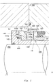
- Fig. 1 is a schematic sectional view showing an overall configuration of a mechanical seal according to the present Example. While a single seal configuration using one mechanical seal will be described in the present Example, the configuration of the present invention may be applied to a double seal configuration using two mechanical seals. A mechanical seal is used to seal an annular gap between a rotating shaft and a housing.
- a mechanical seal 100 includes a rotating ring 110 which rotates with a rotating shaft 200, a stationary ring (static ring) 120 which is fixed to a housing 300, and a floating ring 130 which is provided between the rotating ring 110 and the stationary ring 120.
- the mechanical seal 100 includes a sleeve 140 provided with a cylindrical shaft fixing portion 141 having an inner circumferential surface fixed to an outer circumferential surface of the rotating shaft 200 and a holding portion 142 which extends to an radially outer side of the rotating shaft 200 from the shaft fixing portion 141 and which holds the rotating ring 110.
- the mechanical seal 100 includes a spring 150 as a biasing member which biases the stationary ring 120 with respect to the floating ring 130.
- the rotating ring 110 includes a sliding surface 110a which is one end surface in a direction parallel to the rotating shaft 200 (hereinafter, referred to as an axial direction) and which slides with respect to the floating ring 130.
- the stationary ring 120 includes a pressing surface 120a which is one end surface in the axial direction and which makes contact with the floating ring 130 and presses the floating ring 130 toward a side of the rotating ring 110.
- the floating ring 130 is provided between the rotating ring 110 and the stationary ring 120 in the axial direction without being fixed to other members. Moreover, while the floating ring 130 slides with respect to the rotating ring 110, movement of the floating ring 130 in a rotational direction of the rotating shaft 200 is restricted by a pin 301 provided so as to protrude from the housing 300.
- the floating ring 130 includes a sliding portion 131 which protrudes with respect to the rotating ring 110 and which slides with respect to the sliding surface 110a of the rotating ring 110 at a distal end surface (hereinafter, referred to as a sliding surface 131a) in a protruding direction.
- the floating ring 130 includes a pressed portion 132 as a contacting portion which protrudes with respect to the stationary ring 120 and which is pressed by the pressing surface 120a of the stationary ring 120 at a distal end surface (hereinafter, referred to as a pressed surface 132a) in a protruding direction.
- a pressed portion 132 as a contacting portion which protrudes with respect to the stationary ring 120 and which is pressed by the pressing surface 120a of the stationary ring 120 at a distal end surface (hereinafter, referred to as a pressed surface 132a) in a protruding direction.
- the mechanical seal 100 seals a sealed fluid via the sliding surface 131a and the pressed surface 132a of the floating ring 130.
- the inside of the housing 300 is divided into a fluid side L on which the sealed fluid is sealed via the sliding surface 131a and the pressed surface 132a and an atmosphere side (a non-fluid side) A on which the sealed fluid is not sealed.
- the fluid side L is an radially outer side of the rotating shaft 200 than the sliding surface 131a and the pressed surface 132a
- the atmosphere side A is an radially inner side of the rotating shaft 200 than the sliding surface 131 a and the pressed surface 132a.
- FIG. 2 is a schematic sectional view for explaining forces that act on the respective members of the mechanical seal according to the present Example. Moreover, in Fig. 2 , a part of the components including the sleeve 140 has been omitted. The rotating shaft 200 has also been omitted with the exception of a shaft center O of the rotating shaft 200.
- a side on which the rotating ring is present (a left side in the drawing) will be referred to as a rotating ring side and a side on which the stationary ring is present (a right side in the drawing) will be referred to as a stationary ring side.
- An end surface 121a which is on an opposite side to a side opposing the floating ring 130 and which receives the influence of fluid pressure P of the sealed fluid among end surfaces in the axial direction of the stationary ring 120 is assumed to have an area of S1.
- a force F1 P ⁇ S1 acts on the end surface 121a toward a side of the rotating ring 110 in the axial direction.
- a diameter of a portion at a shortest distance from the shaft center O of the rotating shaft 200 in the end surface 121a (in the present Example, a diameter of a contacting section between the stationary ring 120 and a secondary seal 401 which is an innermost diameter position where the sealed fluid is sealed) is assumed to be R1.
- An end surface 121b which is on a side opposing the floating ring 130 and which receives the influence of fluid pressure P of the sealed fluid among end surfaces in the axial direction of the stationary ring 120 is assumed to have an area of S2.
- the end surface 121b which receives the influence of fluid pressure P includes a surface which receives the influence of fluid pressure P in the pressing surface 120a.
- a force F2 P ⁇ S2 acts on the end surface 121b toward a side of the stationary ring 120 in the axial direction.
- a diameter of a portion at a shortest distance from the shaft center O of the rotating shaft 200 in the end surface 121b (in the present Example, corresponding to an innermost diameter of the pressed surface 132a) is assumed to be R2.
- An end surface 131b which is on a side opposing the rotating ring 110 and which receives the influence of fluid pressure P of the sealed fluid among end surfaces in the axial direction of the floating ring 130 is assumed to have an area of S4.
- a force F4 P ⁇ S4 acts on the end surface 131b toward a side of the stationary ring 120 in the axial direction.
- a diameter of a portion at a shortest distance from the shaft center O of the rotating shaft 200 in the end surface 131b (in the present Example, corresponding to an innermost diameter of the sliding surface 131a) is assumed to be R3.
- a biasing force Fsp is applied to the stationary ring 120 by the spring 150 in a same direction as a direction in which F1 acts so as to maintain a state where the stationary ring 120 is in contact with the floating ring 130.
- the biasing force Fsp so as to satisfy a relationship expressed as F2 ⁇ F1 + Fsp, the stationary ring 120 can maintain a state of contact with the floating ring 130.
- using a spring 150 with a large biasing force Fsp makes assembly work of the mechanical seal 100 challenging.
- the present Example adopts a relationship satisfying F2 ⁇ F1.
- a configuration is adopted in which the area S1 of the end surface 121a of the stationary ring 120 is larger than the area S2 of the end surface 121b of the stationary ring 120.
- a configuration is adopted in which a width from the innermost diameter R1 of the end surface 121a to an outer diameter of the stationary ring 120 is larger than a width from the innermost diameter R2 of the pressed surface 132a to the outer diameter of the stationary ring 120.
- a configuration is adopted which satisfies R2 > R1.
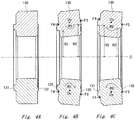
- FIGs. 3A and 3B are diagrams showing states where rotational moment has caused the floating ring provided in the mechanical seal according to the present invention to incline, in which Fig. 3A shows the floating ring configured so as to incline in a direction of R1 in the drawing (counterclockwise). In addition, Fig. 3B shows the floating ring configured so as to incline in a direction of R2 in the drawing (clockwise). Moreover, Figs. 3A and 3B only show a part of a cross section of the floating ring and a depth thereof is omitted. Figs.
- FIG. 4A to 4C are sectional views showing the floating ring in an uninclined state and the floating ring in an inclined state.
- Fig. 4A shows a state where a floating ring configured as shown in Fig. 3A is not inclined and Fig. 4B shows a state where a floating ring configured as shown in Fig. 3A is inclined.
- Fig. 4C shows a state where a floating ring configured as shown in Fig. 3B is inclined.
- a sealing member such as an O ring for sealing the gap between the floating ring 130 and the stationary ring 120 need not be provided. Therefore, problems encountered when providing an O ring which makes positioning of the floating ring 130 difficult under high pressure conditions do not arise.
- a center of moment Oy of the floating ring 130 (a center of rotation: more specifically, a center of moment in each sectional portion shown in Figs. 4A to 4C ) is on an radially outer side than whichever is a smaller diameter between the innermost diameter R3 of the sliding surface 131a and the innermost diameter R2 of the pressed surface 132a.
- the center of rotation Oy is on the radially outer side than the innermost diameter R3.
- the floating ring 130 rotates in the direction of R1 around the center of rotation Oy.
- the center of rotation Oy is on the radially outer side than the innermost diameter R2. Therefore, due to rotational moment, the floating ring 130 rotates in the direction of R2 around the center of rotation Oy.
- An O ring 400 as a sealing member that seals a gap between the holding portion 142 of the sleeve 140 and the rotating ring 110 is provided in a depressed portion that is depressed in the radial direction in the holding portion 142 so as to create a seal by being squashed in the radial direction.
- the O ring 400 does not provide a seal by being squashed in the axial direction (which is a direction in which the rotating ring is displaced) due to pressure of the sealed fluid, a seal can be always provided at a constant contacting pressure without affecting deformation of the rotating ring and without causing a significant change in seal surface pressure due to a magnitude of pressure of the sealed fluid and, for example, a more reliable seal can be provided as compared to a configuration in which an O ring is provided in contact with an end surface 111a of the rotating ring 110 in the axial direction.
- a section where the sealing member and the rotating ring come into contact with each other is on an opposite side to a side of the sealed fluid in the radial direction with respect to the sliding portion (for example, when the sealed fluid is on an outer diameter side of the sliding portion, the opposite side to the outer diameter side or, in other words, an inner diameter side).
- a side on which the sealing member is present in an area of the end surface receiving fluid pressure in the axial direction of the rotating ring can be increased.
- a root portion 131c of the sliding portion 131 of the floating ring 130 (a portion between the sliding portion 131 and the end surface 131b) favorably has a structure having a gradually curving surface or a tapered shape instead of a right angle (a structure making the root portion less susceptible to damage and less likely to create a fluid reservoir) in order to prevent a fluid reservoir of the sealed fluid from being readily created and to make the root portion less susceptible to damage.
Landscapes
- Engineering & Computer Science (AREA)
- General Engineering & Computer Science (AREA)
- Mechanical Engineering (AREA)
- Mechanical Sealing (AREA)
Applications Claiming Priority (2)
| Application Number | Priority Date | Filing Date | Title |
|---|---|---|---|
| JP2014143429 | 2014-07-11 | ||
| PCT/JP2015/069186 WO2016006535A1 (ja) | 2014-07-11 | 2015-07-02 | メカニカルシール |
Publications (1)
| Publication Number | Publication Date |
|---|---|
| EP3168509A1 true EP3168509A1 (de) | 2017-05-17 |
Family
ID=55064171
Family Applications (1)
| Application Number | Title | Priority Date | Filing Date |
|---|---|---|---|
| EP15818217.0A Withdrawn EP3168509A1 (de) | 2014-07-11 | 2015-07-02 | Mechanische dichtung |
Country Status (5)
| Country | Link |
|---|---|
| US (1) | US20170146130A1 (de) |
| EP (1) | EP3168509A1 (de) |
| JP (1) | JPWO2016006535A1 (de) |
| CN (1) | CN106471295A (de) |
| WO (1) | WO2016006535A1 (de) |
Families Citing this family (7)
| Publication number | Priority date | Publication date | Assignee | Title |
|---|---|---|---|---|
| EP3450804B1 (de) * | 2016-04-27 | 2023-09-27 | Eagle Industry Co., Ltd. | Mechanische dichtung |
| US11719191B2 (en) | 2021-06-21 | 2023-08-08 | General Electric Company | Skirted leaf seal apparatus |
| US11703014B2 (en) | 2021-06-29 | 2023-07-18 | General Electric Company | Flexurally actuated self-sealing plunger apparatus |
| US11674447B2 (en) * | 2021-06-29 | 2023-06-13 | General Electric Company | Skirted seal apparatus |
| US11692510B2 (en) | 2021-08-20 | 2023-07-04 | General Electric Company | Plunger seal assembly and sealing method |
| US11655722B1 (en) | 2022-01-19 | 2023-05-23 | General Electric Company | Seal assembly and sealing method |
| DE102022120041B3 (de) * | 2022-08-09 | 2024-01-04 | Eagleburgmann Germany Gmbh & Co. Kg | Gleitringdichtungsanordnung |
Family Cites Families (16)
| Publication number | Priority date | Publication date | Assignee | Title |
|---|---|---|---|---|
| US4489951A (en) * | 1983-08-17 | 1984-12-25 | Ebara Corporation | Mechanical seal |
| GB9103459D0 (en) * | 1991-02-19 | 1991-04-03 | Cross Mfg Co | Brush seal assembly |
| US5143292A (en) * | 1991-05-09 | 1992-09-01 | General Electric Company | Cooled leaf seal |
| US5201530A (en) * | 1991-10-18 | 1993-04-13 | United Technologies Corporation | Multi-layered brush seal |
| DE4211809A1 (de) * | 1992-04-08 | 1993-10-14 | Klein Schanzlin & Becker Ag | Schwimmringdichtung |
| CA2303151C (en) * | 1998-07-13 | 2004-08-31 | Mitsubishi Heavy Industries, Ltd. | Shaft seal and turbine using the shaft seal |
| JP4136973B2 (ja) * | 2004-03-05 | 2008-08-20 | 日本ピラー工業株式会社 | 遊動環形メカニカルシール |
| US8440295B2 (en) * | 2005-04-22 | 2013-05-14 | Eagle Industry Co. Ltd. | Mechanical seal device, sliding element, and method of production thereof |
| DE202005011137U1 (de) * | 2005-07-14 | 2005-09-29 | Burgmann Industries Gmbh & Co. Kg | Gleitringdichtungsanordnung |
| US7708283B2 (en) * | 2006-05-17 | 2010-05-04 | A.W. Chesterton Company | Mechanical seal assembly |
| US7703774B2 (en) * | 2006-09-12 | 2010-04-27 | General Electric Company | Shaft seal using shingle members |
| GB2452967A (en) * | 2007-09-21 | 2009-03-25 | Rolls Royce Plc | A seal and rotor arrangement including a rotor section and a circumferential movable seal around the rotor section |
| JP5514107B2 (ja) * | 2008-07-07 | 2014-06-04 | イーグル工業株式会社 | メカニカルシール装置 |
| JP5259463B2 (ja) * | 2009-03-13 | 2013-08-07 | イーグル工業株式会社 | 高温用デッドエンドシール |
| JP5613529B2 (ja) * | 2010-11-09 | 2014-10-22 | 日本ピラー工業株式会社 | メカニカルシール |
| JP6158205B2 (ja) * | 2012-10-19 | 2017-07-05 | イーグルブルグマンジャパン株式会社 | ベローズシール |
-
2015
- 2015-07-02 EP EP15818217.0A patent/EP3168509A1/de not_active Withdrawn
- 2015-07-02 JP JP2016532906A patent/JPWO2016006535A1/ja active Pending
- 2015-07-02 CN CN201580034934.XA patent/CN106471295A/zh active Pending
- 2015-07-02 WO PCT/JP2015/069186 patent/WO2016006535A1/ja active Application Filing
- 2015-07-02 US US15/320,662 patent/US20170146130A1/en not_active Abandoned
Also Published As
| Publication number | Publication date |
|---|---|
| US20170146130A1 (en) | 2017-05-25 |
| WO2016006535A1 (ja) | 2016-01-14 |
| CN106471295A (zh) | 2017-03-01 |
| JPWO2016006535A1 (ja) | 2017-06-01 |
Similar Documents
| Publication | Publication Date | Title |
|---|---|---|
| EP3168509A1 (de) | Mechanische dichtung | |
| US10240641B2 (en) | Power transmission shaft and propeller shaft for vehicle | |
| EP3070378B1 (de) | Geteilte mechanische dichtung | |
| CN109642675B (zh) | 密封装置 | |
| EP3118494B1 (de) | Dichtungsvorrichtung | |
| EP3392533B1 (de) | Dichtungsvorrichtung | |
| EP2881633B1 (de) | Gleitkomponente | |
| JP5088075B2 (ja) | シールリング | |
| US10612665B2 (en) | Mechanical seal | |
| CN102086907A (zh) | 轴向保持组件 | |
| US20140023459A1 (en) | Snap ring | |
| US11221074B2 (en) | Mechanical seal | |
| EP3643949B1 (de) | Mechanische dichtung | |
| JP6707614B2 (ja) | シールリングおよびシールリングの製造方法 | |
| JP6357865B2 (ja) | シールリング | |
| JP6361277B2 (ja) | シールリング | |
| EP3156700B1 (de) | Mechanische dichtung | |
| JP2010144789A (ja) | バックアップリングおよび密封装置 | |
| JP6504060B2 (ja) | クリーナ用単列玉軸受 | |
| JP2005114007A (ja) | 密封装置 | |
| JP5807380B2 (ja) | ボールねじ | |
| JP6394226B2 (ja) | 密封装置 | |
| JP5707887B2 (ja) | 密封構造 | |
| US8985591B2 (en) | Sealing apparatus | |
| JP2012154483A (ja) | シールリング |
Legal Events
| Date | Code | Title | Description |
|---|---|---|---|
| STAA | Information on the status of an ep patent application or granted ep patent |
Free format text: STATUS: THE INTERNATIONAL PUBLICATION HAS BEEN MADE |
|
| PUAI | Public reference made under article 153(3) epc to a published international application that has entered the european phase |
Free format text: ORIGINAL CODE: 0009012 |
|
| STAA | Information on the status of an ep patent application or granted ep patent |
Free format text: STATUS: REQUEST FOR EXAMINATION WAS MADE |
|
| 17P | Request for examination filed |
Effective date: 20161229 |
|
| AK | Designated contracting states |
Kind code of ref document: A1 Designated state(s): AL AT BE BG CH CY CZ DE DK EE ES FI FR GB GR HR HU IE IS IT LI LT LU LV MC MK MT NL NO PL PT RO RS SE SI SK SM TR |
|
| AX | Request for extension of the european patent |
Extension state: BA ME |
|
| 18W | Application withdrawn |
Effective date: 20170427 |
|
| STAA | Information on the status of an ep patent application or granted ep patent |
Free format text: STATUS: THE APPLICATION HAS BEEN WITHDRAWN |