EP3167174B1 - Abgasanlage für verbrennungsmotor und verfahren zum heizen eines katalysators - Google Patents
Abgasanlage für verbrennungsmotor und verfahren zum heizen eines katalysators Download PDFInfo
- Publication number
- EP3167174B1 EP3167174B1 EP15734197.5A EP15734197A EP3167174B1 EP 3167174 B1 EP3167174 B1 EP 3167174B1 EP 15734197 A EP15734197 A EP 15734197A EP 3167174 B1 EP3167174 B1 EP 3167174B1
- Authority
- EP
- European Patent Office
- Prior art keywords
- bypass path
- exhaust gas
- valve member
- exhaust system
- turbine
- Prior art date
- Legal status (The legal status is an assumption and is not a legal conclusion. Google has not performed a legal analysis and makes no representation as to the accuracy of the status listed.)
- Active
Links
Images

Classifications
-
- F—MECHANICAL ENGINEERING; LIGHTING; HEATING; WEAPONS; BLASTING
- F02—COMBUSTION ENGINES; HOT-GAS OR COMBUSTION-PRODUCT ENGINE PLANTS
- F02B—INTERNAL-COMBUSTION PISTON ENGINES; COMBUSTION ENGINES IN GENERAL
- F02B37/00—Engines characterised by provision of pumps driven at least for part of the time by exhaust
- F02B37/12—Control of the pumps
- F02B37/18—Control of the pumps by bypassing exhaust from the inlet to the outlet of turbine or to the atmosphere
- F02B37/183—Arrangements of bypass valves or actuators therefor
-
- F—MECHANICAL ENGINEERING; LIGHTING; HEATING; WEAPONS; BLASTING
- F01—MACHINES OR ENGINES IN GENERAL; ENGINE PLANTS IN GENERAL; STEAM ENGINES
- F01N—GAS-FLOW SILENCERS OR EXHAUST APPARATUS FOR MACHINES OR ENGINES IN GENERAL; GAS-FLOW SILENCERS OR EXHAUST APPARATUS FOR INTERNAL-COMBUSTION ENGINES
- F01N13/00—Exhaust or silencing apparatus characterised by constructional features
-
- F—MECHANICAL ENGINEERING; LIGHTING; HEATING; WEAPONS; BLASTING
- F01—MACHINES OR ENGINES IN GENERAL; ENGINE PLANTS IN GENERAL; STEAM ENGINES
- F01N—GAS-FLOW SILENCERS OR EXHAUST APPARATUS FOR MACHINES OR ENGINES IN GENERAL; GAS-FLOW SILENCERS OR EXHAUST APPARATUS FOR INTERNAL-COMBUSTION ENGINES
- F01N3/00—Exhaust or silencing apparatus having means for purifying, rendering innocuous, or otherwise treating exhaust
- F01N3/08—Exhaust or silencing apparatus having means for purifying, rendering innocuous, or otherwise treating exhaust for rendering innocuous
- F01N3/10—Exhaust or silencing apparatus having means for purifying, rendering innocuous, or otherwise treating exhaust for rendering innocuous by thermal or catalytic conversion of noxious components of exhaust
- F01N3/101—Three-way catalysts
-
- F—MECHANICAL ENGINEERING; LIGHTING; HEATING; WEAPONS; BLASTING
- F01—MACHINES OR ENGINES IN GENERAL; ENGINE PLANTS IN GENERAL; STEAM ENGINES
- F01N—GAS-FLOW SILENCERS OR EXHAUST APPARATUS FOR MACHINES OR ENGINES IN GENERAL; GAS-FLOW SILENCERS OR EXHAUST APPARATUS FOR INTERNAL-COMBUSTION ENGINES
- F01N3/00—Exhaust or silencing apparatus having means for purifying, rendering innocuous, or otherwise treating exhaust
- F01N3/08—Exhaust or silencing apparatus having means for purifying, rendering innocuous, or otherwise treating exhaust for rendering innocuous
- F01N3/10—Exhaust or silencing apparatus having means for purifying, rendering innocuous, or otherwise treating exhaust for rendering innocuous by thermal or catalytic conversion of noxious components of exhaust
- F01N3/18—Exhaust or silencing apparatus having means for purifying, rendering innocuous, or otherwise treating exhaust for rendering innocuous by thermal or catalytic conversion of noxious components of exhaust characterised by methods of operation; Control
- F01N3/20—Exhaust or silencing apparatus having means for purifying, rendering innocuous, or otherwise treating exhaust for rendering innocuous by thermal or catalytic conversion of noxious components of exhaust characterised by methods of operation; Control specially adapted for catalytic conversion
- F01N3/2006—Periodically heating or cooling catalytic reactors, e.g. at cold starting or overheating
-
- F—MECHANICAL ENGINEERING; LIGHTING; HEATING; WEAPONS; BLASTING
- F01—MACHINES OR ENGINES IN GENERAL; ENGINE PLANTS IN GENERAL; STEAM ENGINES
- F01N—GAS-FLOW SILENCERS OR EXHAUST APPARATUS FOR MACHINES OR ENGINES IN GENERAL; GAS-FLOW SILENCERS OR EXHAUST APPARATUS FOR INTERNAL-COMBUSTION ENGINES
- F01N3/00—Exhaust or silencing apparatus having means for purifying, rendering innocuous, or otherwise treating exhaust
- F01N3/08—Exhaust or silencing apparatus having means for purifying, rendering innocuous, or otherwise treating exhaust for rendering innocuous
- F01N3/10—Exhaust or silencing apparatus having means for purifying, rendering innocuous, or otherwise treating exhaust for rendering innocuous by thermal or catalytic conversion of noxious components of exhaust
- F01N3/24—Exhaust or silencing apparatus having means for purifying, rendering innocuous, or otherwise treating exhaust for rendering innocuous by thermal or catalytic conversion of noxious components of exhaust characterised by constructional aspects of converting apparatus
- F01N3/28—Construction of catalytic reactors
- F01N3/2892—Exhaust flow directors or the like, e.g. upstream of catalytic device
-
- F—MECHANICAL ENGINEERING; LIGHTING; HEATING; WEAPONS; BLASTING
- F02—COMBUSTION ENGINES; HOT-GAS OR COMBUSTION-PRODUCT ENGINE PLANTS
- F02B—INTERNAL-COMBUSTION PISTON ENGINES; COMBUSTION ENGINES IN GENERAL
- F02B37/00—Engines characterised by provision of pumps driven at least for part of the time by exhaust
- F02B37/12—Control of the pumps
- F02B37/18—Control of the pumps by bypassing exhaust from the inlet to the outlet of turbine or to the atmosphere
-
- F—MECHANICAL ENGINEERING; LIGHTING; HEATING; WEAPONS; BLASTING
- F02—COMBUSTION ENGINES; HOT-GAS OR COMBUSTION-PRODUCT ENGINE PLANTS
- F02B—INTERNAL-COMBUSTION PISTON ENGINES; COMBUSTION ENGINES IN GENERAL
- F02B37/00—Engines characterised by provision of pumps driven at least for part of the time by exhaust
- F02B37/12—Control of the pumps
- F02B37/22—Control of the pumps by varying cross-section of exhaust passages or air passages, e.g. by throttling turbine inlets or outlets or by varying effective number of guide conduits
-
- F—MECHANICAL ENGINEERING; LIGHTING; HEATING; WEAPONS; BLASTING
- F02—COMBUSTION ENGINES; HOT-GAS OR COMBUSTION-PRODUCT ENGINE PLANTS
- F02B—INTERNAL-COMBUSTION PISTON ENGINES; COMBUSTION ENGINES IN GENERAL
- F02B51/00—Other methods of operating engines involving pretreating of, or adding substances to, combustion air, fuel, or fuel-air mixture of the engines
- F02B51/02—Other methods of operating engines involving pretreating of, or adding substances to, combustion air, fuel, or fuel-air mixture of the engines involving catalysts
-
- F—MECHANICAL ENGINEERING; LIGHTING; HEATING; WEAPONS; BLASTING
- F01—MACHINES OR ENGINES IN GENERAL; ENGINE PLANTS IN GENERAL; STEAM ENGINES
- F01N—GAS-FLOW SILENCERS OR EXHAUST APPARATUS FOR MACHINES OR ENGINES IN GENERAL; GAS-FLOW SILENCERS OR EXHAUST APPARATUS FOR INTERNAL-COMBUSTION ENGINES
- F01N2240/00—Combination or association of two or more different exhaust treating devices, or of at least one such device with an auxiliary device, not covered by indexing codes F01N2230/00 or F01N2250/00, one of the devices being
- F01N2240/36—Combination or association of two or more different exhaust treating devices, or of at least one such device with an auxiliary device, not covered by indexing codes F01N2230/00 or F01N2250/00, one of the devices being an exhaust flap
-
- F—MECHANICAL ENGINEERING; LIGHTING; HEATING; WEAPONS; BLASTING
- F01—MACHINES OR ENGINES IN GENERAL; ENGINE PLANTS IN GENERAL; STEAM ENGINES
- F01N—GAS-FLOW SILENCERS OR EXHAUST APPARATUS FOR MACHINES OR ENGINES IN GENERAL; GAS-FLOW SILENCERS OR EXHAUST APPARATUS FOR INTERNAL-COMBUSTION ENGINES
- F01N2340/00—Dimensional characteristics of the exhaust system, e.g. length, diameter or volume of the exhaust apparatus; Spatial arrangements of exhaust apparatuses
- F01N2340/06—Arrangement of the exhaust apparatus relative to the turbine of a turbocharger
-
- F—MECHANICAL ENGINEERING; LIGHTING; HEATING; WEAPONS; BLASTING
- F01—MACHINES OR ENGINES IN GENERAL; ENGINE PLANTS IN GENERAL; STEAM ENGINES
- F01N—GAS-FLOW SILENCERS OR EXHAUST APPARATUS FOR MACHINES OR ENGINES IN GENERAL; GAS-FLOW SILENCERS OR EXHAUST APPARATUS FOR INTERNAL-COMBUSTION ENGINES
- F01N2430/00—Influencing exhaust purification, e.g. starting of catalytic reaction, filter regeneration, or the like, by controlling engine operating characteristics
-
- Y—GENERAL TAGGING OF NEW TECHNOLOGICAL DEVELOPMENTS; GENERAL TAGGING OF CROSS-SECTIONAL TECHNOLOGIES SPANNING OVER SEVERAL SECTIONS OF THE IPC; TECHNICAL SUBJECTS COVERED BY FORMER USPC CROSS-REFERENCE ART COLLECTIONS [XRACs] AND DIGESTS
- Y02—TECHNOLOGIES OR APPLICATIONS FOR MITIGATION OR ADAPTATION AGAINST CLIMATE CHANGE
- Y02T—CLIMATE CHANGE MITIGATION TECHNOLOGIES RELATED TO TRANSPORTATION
- Y02T10/00—Road transport of goods or passengers
- Y02T10/10—Internal combustion engine [ICE] based vehicles
- Y02T10/12—Improving ICE efficiencies
Definitions
- This invention relates to an exhaust system for an internal combustion engine and a method of heating a catalytic converter associated with an internal combustion engine.
- catalytic converters catalytically oxidise HCs and CO to CO 2 and H 2 O, whilst reducing NO x to nitrogen, these are so-called three-way catalytic converters.
- Such converters typically comprise a ceramic monolith, or sometimes a metallic foil monolith, carrying catalytic precious metals such as platinum, palladium and so on.
- a diesel oxidation catalyst is typically used, sometimes coupled with other treatment means for the reduction of NO x to nitrogen.
- turbochargers are usually provided to enhance engine performance.
- components of the turbocharger such as the turbine housing, may be cast from steels with high thermal inertia.
- turbochargers typically have a high thermal inertia and, because the turbocharger is usually positioned upstream of the catalytic converter, cause a reduction in exhaust gas temperature reaching the catalytic converter in, or just after, start-up conditions. Accordingly, until such time as the entire exhaust system reaches at least a degree of thermal equilibrium it is possible that the catalytic converter will not be heated to its optimum operating temperature and/or to the light off temperature and hence will not be as effective in reducing emissions.
- an exhaust system for an internal combustion engine comprising a turbocharger having a turbine, a bypass path arranged to allow exhaust gas to bypass the turbine, a chamber and a catalytic converter, wherein the bypass path is selectively openable and closable by a wastegate valve member to allow or prevent exhaust gas flowing from the engine to bypass the turbine and thereby enter the chamber wherein the wastegate valve member is seated on a valve seat when in the closed condition, wherein when the wastegate valve member is fully open exhaust gas is diverted by the wastegate valve member to directly impinge upon the leading face of a monolith of the catalytic converter, wherein exhaust gas exiting the turbine is directed to directly impinge upon the leading face of the monolith of the catalytic converter; and wherein exhaust gas after diversion by the wastegate valve member is parallel to a principal flow of exhaust gas exiting the turbine.
- valve member directs hot gases onto the leading face of the catalytic converter element, for example during a start-up or early phase of an engine cycle, to heat the catalytic converter to or towards an optimum performance temperature.
- the valve member may be pivotable, at its fully open position, to an angle of 30 to 70°, for example from 35 to 65, say 36 to 63°, preferably 40 to 60°, say 40 to 50° with respect to the plane defined by the valve seat.
- the valve member may be pivotable, at its fully open position, to an angle of 0°, or greater than 0°, to 60°, or less than 60°, with respect to the principal flow axis along the bypass path. When the valve member is at an angle of 0° with respect to the principal flow axis the valve member will be parallel to the principal flow axis.
- the valve member may be pivoted to an angle of from 5 to 35° to the principal flow axis, optionally from 10 to 30°. Alternatively, the valve member may be pivoted to an angle of 45 to 60° with respect to the principal flow axis when the valve member is in its fully open position.
- the bypass path may be defined by a conduit.
- the bypass path may or may not protrude into a chamber.
- the wastegate may, but need not, pivot into and towards the centre of the chamber.
- the or at least some gases exiting the bypass path may exhaust along a flow path which is inclined at an angle to a or the principal flow path axis along the or a chamber.
- valve member in its fully open position, may be positioned or located at or towards the centre of the chamber.
- the valve member opens in a direction which takes the valve member away from the wall of the chamber.
- the valve member may be arranged to at least partially divert gases exiting the bypass path along a non-parallel flow path.
- the valve member may be positioned such that gases exiting the bypass flow path are at least partially directed to or towards a downstream principal flow axis, for example a downstream principal flow axis aligned with a principal axis of a chamber.
- allowing gases to bypass the turbocharger just after start-up of the engine ensures that the catalytic converter is heated by the exhaust gases faster than would otherwise happen.
- using the wastegate valve to affect the flow direction of the gases ensures that the hot gases reach their target (the catalytic converter) as quickly as possible.
- the wastegate valve is operable to direct at least some of the gases exiting the bypass path onto the leading face, preferably at or towards the centre ( i.e. substantially away from the edges) of the leading face, of the catalytic converter, wherein the heat flux can conduct radially outwards.
- the bypass path may have a principal flow axis.
- the or a principal flow axis of the bypass path may be at an angle of between 30 and 70° to the principal axis of the chamber. In an example embodiment, the angle is 40°.
- the bypass path may or may not protrude into the chamber.
- the wastegate valve member engages or is engageable with a valve seat, provided on one end of the bypass path.
- the plane defined by the valve seat at the end of bypass path may be at an angle of less than 90° to 45°, say from 50 to 85°, for example from 55 to 80°, from 60 to 75°, say from 60 to 70° to the principal flow axis along the bypass path. Additionally or alternatively, the plane defined by the valve seat may be non-parallel to the leading face of the monolith.
- the wastegate valve may be actuated by an electrical actuator or with a vacuum actuator, or other mechanical actuator.
- the wastegate valve member may pivot between its open position, which may be the default position, to its closed position where it engages, for example is seated on, the valve seat at the end of the bypass path.
- the turbocharger may be a twin-scroll turbocharger.
- a method of heating to an effective temperature a catalytic converter of an engine comprising an exhaust system according to the above-described aspect, the method comprising causing at least some of the gases from the engine to bypass the turbocharger turbine along the bypass path and diverting the gases exiting the bypass path by means of the wastegate valve member to directly impinge onto the leading face of the monolith of the catalytic converter, wherein exhaust gas exiting the turbine is also directed to directly impinge upon the leading face of the monolith of the catalytic converter, and exhaust gas after diversion by the wastegate valve is parallel to the principal flow axis of exhaust gas exiting the turbine.
- An advantage of this method is that the time for the catalytic converter to reach a desired operating temperature is reduced, thereby reducing emissions.
- an engine E for a motor vehicle The engine E is provided with a turbocharger unit T which is operably connected and secured to an exhaust system ES.
- the turbocharger unit T comprises a turbocharger compressor housing 2 and a turbocharger turbine housing 3.
- the exhaust system ES comprises a catalyst inlet cone 4, a primary catalytic converter 5a, a secondary catalytic converter 5b coupled to the rest of the exhaust system ES which typically directs exhaust emissions toward the rear of the vehicle.
- a catalyst downpipe 9 interconnects the primary and secondary catalytic converters 5a, 5b.
- the turbocharger unit T may comprise a twin scroll turbocharger but any turbocharger unit may be used. It will be understood that the present invention may be especially applicable to vehicles that are provided with twin scroll turbochargers, because such turbochargers typically have higher thermal mass than single scroll turbochargers, so they tend to delay light off of the catalytic converter by more than single scroll turbochargers.
- the turbocharger unit T comprises a turbine (not shown in Figure 1 ) provided within the turbine housing 3 and arranged to be driven by impinging gases exhausting from the engine E to drive a compressor (not shown) housed in the compressor housing 2 in the usual manner.
- the turbocharger unit T also comprises a wastegate actuator 7a and a wastegate crank 7b, the purpose of which will be explained below.
- gases exiting the engine E are forced either along a bypass path 6 or through the turbine housing 3 to engage the turbine. In either case, the gas will flow into the inlet cone 4 and then through the primary catalytic converter 5a and into the exhaust system ES, and from there out of the vehicle.
- Figure 2 shows a partial cut away of the turbine housing 3 of the turbocharger unit T.
- the turbine housing 3 is operably connected to an exhaust manifold 10 which directs gases from the engine E into the turbocharger unit T. Gases flowing through the turbine housing 3 can flow either via the turbine volute 11 to engage the turbine wheel 12 or via the bypass path 6. Gases exiting the turbine volute 11, and subsequent driveably engaging the turbine wheel 12 will enter an expansion chamber 13 with a principal flow axis FC.
- the bypass path 6 is a conduit with a proximal end 6a communicating with the turbine housing and a distal end 6b communicating with the expansion chamber 13 and having a principal flow axis FA therebetween.
- the bypass path 6 protrudes into the chamber 13 and is occluded (or occludable) by a wastegate valve 8 which is shown in its open state.
- the wastegate valve 8 seats on the wastegate valve seat 6c at the distal end 6b of the bypass path 6.
- the wastegate valve 8 In its open state, the wastegate valve 8 is pivoted away from the bypass path 6 about a wastegate pivot axis P.
- the wastegate valve 8 is actuated and moved between its closed and open states by action of the wastegate actuator 7a, which is preferably an electric actuator 7 (not shown).
- the actuator 7a may comprise a pair of actuation arms. Reciprocal linear motion of the arms causes rotation back and forth of the crank 7b which, in turn, is operably connected to the wastegate valve 8 to cause pivoting motion of the wastegate valve 8 about pivot point P to pivot the valve 8 from the seat 6c into and/or towards the centre of the chamber 13.
- the monolith M is held within the catalytic converter unit 5a as shown.
- the monolith M has a leading face M LF which is the face downstream of the chamber 13 and catalyst inlet cone 4.
- the principal flow path axis FA of and along the bypass path 6 is shown.
- the distal end 6b of the flow path terminates in a valve seat 6c for the wastegate valve 8.
- the valve seat 6c at the distal end 6b sits in a plane VP which is non-orthogonal to the principal flow axis FA of the bypass path 6 and which is non-parallel to the leading face M LF of the monolith M.
- the principal flow path axis FC along the chamber 13 is shown extending from the proximal end 13a of the chamber 13, where gases are exhausted from the turbine wheel 12, to the distal end 13b of the chamber 13, to meet the leading face M LF of the monolith M.
- the principal flow axis path FC along the chamber 13 may be at an angle of between 30 and 70° to the principal axis FA of the chamber along the bypass path 6. In an example embodiment the angle is 40°. It is beneficial for the gases exhausted from the turbine to be directed to the leading face of the monolith M, as this reduces the amount of energy lost from the gases before they reach the monolith M. Although the gases that flow through the turbine are likely to lose more energy than the gases flowing through the bypass path 6, they still deliver useful energy to the monolith M. This may be especially important when the engine is operating under high load conditions, as the opening angle of the valve 8 may be relatively small to encourage a greater proportion of the exhaust gas to flow through turbine 12 rather than bypass path 6. This makes the gases that flow through the turbine 12 particularly important in delivering energy to the monolith M.
- the electric actuator 7a is able to open the wastegate valve 8 to a large angle in respect to the principal flow path axis FA.
- the angle may be varied up to less than 90°, and is preferably from 55 to 75°, say from 60 to 70°.
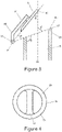
- FIG 3 shows a close up of the distal end 6b of the bypass path 6, with the wastegate valve 8 unseated from the valve seat 6c in an open state 8b.
- the wastegate valve 8 comprises a valve member 80 mounted on an arm 81 which is connected via a crank 82 to a pivot member 83, which pivots about the pivot point P.
- the angle ' ⁇ ' between the plane defined by the base of the valve member 80 and that defined by the plane of the valve seat VP is from 30 to 70°, preferably 40 to 50°.
- the angle ' ⁇ ' between the plane of the valve seat VP and the walls of the bypass path 6 is from greater than 90 to 135°, preferably 105 to 120°.
- the angle ⁇ is 45° and the angle ⁇ is 113°.
- the angle ' ⁇ ' between the plane of the valve seat VP and the principal flow axis FA is from less than 90 to 45°. In a specific example the angle ⁇ is 67°.
- the angle ' ⁇ ' between the plane defined by the valve member 80 and the principal flow axis FA is preferably from 0°, or greater than 0°, to 60°, or less than 60°.
- the valve member 80 may be pivoted to an angle ⁇ of from 10 to 30° to the principal flow axis FA. In a specific example the angle ⁇ may be from 20 to 25°, say 23°.
- the valve seat 6c situated at the distal end 6b of the bypass path 6, has a peripheral wall 61, and a transverse portion 62 which extends diametrically across the bypass path 6 to separate the flow path into two equal portions.
- the purpose of the transverse portion 62 is to support the valve member 80 when the wastegate valve 8 is in its closed state 8b.
- the wastegate valve 8 In use, and as shown in Figure 5 , for example at start-up of an engine E, the wastegate valve 8 is held in its open state 8a by the electric actuator 7a (not shown). At this open state 8a, the wastegate valve 8 describes an angle of 45° to the plane VP. Gas which exhausts the engine E flows into the turbocharger unit T and can either flow via the turbine 12 or via the bypass path 6. Typically from about 10 to 80 v/v%, say about 30 to 70 v/v%, for example 55 to 65 v/v%, of the gas will flow via the bypass path 6, the remainder will flow via the turbine 12.
- Hot gas flowing through the bypass path 6 and along the principal flow axis FA will flow out past the distal end 6b of the bypass path 6 and be diverted along a principal flow axis FA' towards the leading face M LF of the monolith M by the valve member 80 of the bypass valve 8, which is in its open state 8a.
- bypass valve 8 encourages gas FA' exiting the distal end 6b of the bypass path 6 to flow along or parallel to the principal flow path axis FC and come into contact with the monolith M. Because the gases are encouraged to flow along or parallel to the principal flow path axis FC towards the monolith M they do not come into contact with the walls of the chamber 13 and hence transfer an optimum amount of heat to the monolith M. This leads to rapid heating of the monolith M to or towards the monolith light off temperature and thereby reduces emissions.
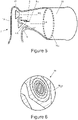
- Figure 6 provides a heat map of the leading face M LF of the monolith M after use of the bypass valve 8 of the invention.
- the heat map clearly shows the greatest heating is felt at or towards the centre of the leading face M LF , thereby indicating that gases are effectively directed towards the centre of the monolith M rather than towards the walls of the housing 13 and/or the walls of the cone 4.
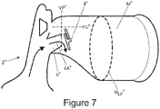
- FIG. 7 shows a wastegate valve design which has a valve seat plane VP" orthogonal to the principal flow direction FC" of the gases through the chamber and a wastegate valve 8" which opens to a shallow angle (as is the case with prior art wastegate valves).
- the flow direction of gases FA" is towards the walls of the chamber and consequently towards one side of the monolith M", thereby wasting valuable heat energy and not maximising the heat flow to heat the monolith towards the light-off temperature.
- the wastegate valve 8 can be brought to its closed state 8a by action of the electric actuator 7a (i.e. bringing the valve member 80 into contact with valve seat 6c) to ensure that all of the gas exhausted from the engine E is directed via the turbine wheel 12.
- the electric actuator 7a may intermittently open and close the wastegate valve 8 to ensure effective operation of the associated vehicle (for example, sometimes it may be preferable to bleed off exhaust gas from the impeller path to ensure optimum operating efficiency of the turbocharger unit T).
Landscapes
- Engineering & Computer Science (AREA)
- Chemical & Material Sciences (AREA)
- Chemical Kinetics & Catalysis (AREA)
- Combustion & Propulsion (AREA)
- Mechanical Engineering (AREA)
- General Engineering & Computer Science (AREA)
- Health & Medical Sciences (AREA)
- Toxicology (AREA)
- Materials Engineering (AREA)
- Supercharger (AREA)
- Exhaust Gas After Treatment (AREA)
Claims (14)
- Auspuffgassystem für einen Verbrennungsmotor (E), der einen Turbolader (T) umfasst, der eine Turbine (11, 12), einen Umgehungsweg (6), der angeordnet ist, um zu ermöglichen, dass Auspuffgas die Turbine (11, 12) umgeht, eine Kammer (13) und einen Katalysator (5a) aufweist, wobei der Umgehungsweg (6) durch ein Wastegate-Ventilelement (80) wahlweise geöffnet und geschlossen werden kann, um zu ermöglichen oder verhindern, dass Auspuffgas aus dem Motor (E) strömt, um die Turbine (11, 12) zu umgehen und dadurch in die Kammer (13) eintritt, wobei das Wastegate-Ventilelement (80) auf einem Ventilsitz (6c) sitzt, wenn es in einem geschlossenen Zustand ist, wobei, wenn das Wastegate-Ventilelement (80) vollständig geöffnet ist, Auspuffgas durch das Wastegate-Ventilelement (80) umgeleitet wird, um auf die Vorderfläche (MLF) eines Monolithen des Katalysators (5a) direkt aufzutreffen, wobei das Auspuffgas, das aus der Turbine (11, 12) austritt, gelenkt wird, um auf die Vorderfläche (MLF) des Monolithen des Katalysators (5a) direkt aufzutreffen; und
wobei das Auspuffgas nach einer Umleitung durch das Wastegate-Ventilelement (80) parallel zu einer Hauptströmung des Auspuffgases ist, das aus der Turbine (11, 12) austritt. - Auspuffgassystem nach Anspruch 1, wobei der Ventilsitz (6c) eine Ebene definiert, die in Gebrauch nicht orthogonal zu einer Hauptströmungsachse des Auspuffgases ist, das entlang des Umgehungsweges (6) strömt.
- Auspuffgassystem nach Anspruch 2, wobei das Wastegate-Ventilelement (80) in seiner vollständig geöffneten Position zu einem Winkel hinsichtlich der Ebene, die durch den Ventilsitz (6c) definiert ist, schwenkbar ist, wobei der Winkel von 30 bis 70° oder von 35 bis 65 oder 36 bis 63° oder 40 bis 60° oder von 40 bis 50° beträgt.
- Auspuffgassystem nach einem der vorhergehenden Ansprüche, wobei das Wastegate-Ventilelement (80) in Gebrauch in seiner vollständig geöffneten Position zu einem Winkel von 0° bis 60° hinsichtlich der Hauptströmungsachse des Auspuffgases entlang des Umgehungsweges (6) schwenkbar ist.
- Auspuffgassystem nach Anspruch 4, wobei das Wastegate-Ventilelement (80) in Gebrauch zu einem Winkel von 45 bis 60° zu der Hauptströmungsachse des Auspuffgases, das entlang des Umgehungsweges (6) strömt, schwenkbar ist.
- Auspuffgassystem nach einem der vorhergehenden Ansprüche, wobei der Umgehungsweg (6) wenigstens teilweise durch eine Leitung bereitgestellt ist, wobei der Ventilsitz (6c) an einem distalen Ende der Leitung bereitgestellt ist, wobei der Umgehungsweg (6) optional angeordnet ist, um in die Kammer (13) flussabwärts davon hineinzuragen.
- Auspuffgassystem nach einem der vorhergehenden Ansprüche, wobei das Wastegate-Ventilelement (80) in die Mitte der Kammer (13) flussabwärts des Umgehungsweges (6) hinein und/oder auf diese zu schwenkt.
- Auspuffgassystem nach einem der vorhergehenden Ansprüche, wobei das oder wenigstens einige Gase, die aus dem Umgehungsweg (6) austreten, entlang eines Strömungsweges auspuffen, der in einem Winkel zu einer Hauptströmungswegachse entlang der Kammer (13) geneigt ist.
- Auspuffgassystem nach einem der vorhergehenden Ansprüche, wobei die Ebene, die durch den Ventilsitz (6c) an dem Ende des Umgehungsweges (6) definiert ist, in Gebrauch in einem Winkel von 90° bis 45° oder von 50 bis 85° oder von 55 bis 80° oder von 60 bis 75° oder von 60 bis 70° zu der Hauptströmungsachse des Auspuffgases sein kann, das entlang des Umgehungsweges (6) strömt.
- Auspuffgassystem nach einem der vorhergehenden Ansprüche, wobei die Ebene, die durch den Ventilsitz (6c) definiert ist, nicht parallel zu der Vorderfläche (MLF) des Monolithen ist.
- Auspuffgassystem nach einem der vorhergehenden Ansprüche, das einen Aktuator (7a) umfasst, um das Wastegate-Ventilelement (80) zu öffnen und schließen, wobei der Aktuator (7a) aus einem elektrischen Aktuator, einem Unterdruckaktuator und einem mechanischen Aktuator ausgewählt ist.
- Auspuffgassystem nach einem der vorhergehenden Ansprüche, wobei der Turbolader (T) ein Twin-Scroll-Turbolader ist.
- Verfahren zum Erwärmen auf eine wirksame Temperatur eines Katalysators eines Motors, der ein Auspuffgassystem nach einem der vorhergehenden Ansprüche umfasst, wobei das Verfahren ein Bewirken, dass wenigstens einige der Gase aus dem Motor die Turboladerturbine entlang des Umgehungsweges umgehen und ein Umleiten der Gase umfasst, die aus dem Umgehungsweg mittels des Wastegate-Ventilelements austreten, um auf die Vorderfläche des Monolithen des Katalysators direkt aufzutreffen, wobei das Auspuffgas, das aus der Turbine austritt, ebenso gelenkt wird, um auf die Vorderfläche des Monolithen des Katalysators direkt aufzutreffen, und
wobei das Auspuffgas nach der Umleitung durch das Wastegate-Ventil parallel zu der Hauptströmungsachse des Auspuffgases ist, das aus der Turbine austritt. - Verfahren nach Anspruch 13, wobei der Turbolader ein Twin-Scroll-Turbolader ist.
Applications Claiming Priority (2)
| Application Number | Priority Date | Filing Date | Title |
|---|---|---|---|
| GB1412227.9A GB2528097A (en) | 2014-07-09 | 2014-07-09 | Wastegate valve |
| PCT/EP2015/065444 WO2016005370A1 (en) | 2014-07-09 | 2015-07-07 | Wastegate valve |
Publications (2)
| Publication Number | Publication Date |
|---|---|
| EP3167174A1 EP3167174A1 (de) | 2017-05-17 |
| EP3167174B1 true EP3167174B1 (de) | 2022-04-27 |
Family
ID=51410878
Family Applications (1)
| Application Number | Title | Priority Date | Filing Date |
|---|---|---|---|
| EP15734197.5A Active EP3167174B1 (de) | 2014-07-09 | 2015-07-07 | Abgasanlage für verbrennungsmotor und verfahren zum heizen eines katalysators |
Country Status (5)
| Country | Link |
|---|---|
| US (2) | US20170152793A1 (de) |
| EP (1) | EP3167174B1 (de) |
| CN (1) | CN106662005A (de) |
| GB (2) | GB2528097A (de) |
| WO (1) | WO2016005370A1 (de) |
Families Citing this family (26)
| Publication number | Priority date | Publication date | Assignee | Title |
|---|---|---|---|---|
| DE102015007414A1 (de) * | 2015-06-06 | 2016-12-08 | Man Truck & Bus Ag | Abgasstrang für eine Brennkraftmaschine |
| US10526958B2 (en) * | 2016-03-23 | 2020-01-07 | Borgwarner Inc. | Reverse offset wastegate valve assembly for improved catalyst light-off performance |
| DE102016119255A1 (de) * | 2016-10-10 | 2018-04-12 | Ihi Charging Systems International Gmbh | Abgasführungsabschnitt für einen Abgasturbolader und Abgasstrang für eine Verbrennungskraftmaschine sowie Verfahren zum Betreiben eines Abgasturboladers |
| JP6547783B2 (ja) * | 2017-02-24 | 2019-07-24 | トヨタ自動車株式会社 | 内燃機関の排気システム |
| JP6772901B2 (ja) * | 2017-03-07 | 2020-10-21 | トヨタ自動車株式会社 | 内燃機関の排気システム |
| JP6589944B2 (ja) * | 2017-07-03 | 2019-10-16 | トヨタ自動車株式会社 | 内燃機関の排気システム |
| JP6834862B2 (ja) * | 2017-09-08 | 2021-02-24 | トヨタ自動車株式会社 | ターボチャージャ |
| JP6606536B2 (ja) * | 2017-11-09 | 2019-11-13 | アイシン高丘株式会社 | 触媒コンバータ |
| US10590837B2 (en) | 2017-12-15 | 2020-03-17 | Fca Us Llc | Turbocharger wastegate assembly |
| JP6919576B2 (ja) * | 2018-01-16 | 2021-08-18 | トヨタ自動車株式会社 | 内燃機関の排気構造 |
| JP6844556B2 (ja) * | 2018-02-09 | 2021-03-17 | トヨタ自動車株式会社 | 内燃機関の排気浄化装置 |
| JP6629898B2 (ja) * | 2018-02-27 | 2020-01-15 | 本田技研工業株式会社 | 内燃機関の排気浄化装置 |
| JP7116604B2 (ja) * | 2018-06-25 | 2022-08-10 | 株式会社Subaru | エンジン |
| JP2020051394A (ja) * | 2018-09-28 | 2020-04-02 | ダイハツ工業株式会社 | ウェイストゲートバルブの構造 |
| DE112019005041T5 (de) * | 2018-10-08 | 2021-10-14 | Borgwarner Inc. | Wastegateanordnung zur verwendung in einem turbolader und diese umfassendes system |
| US10590793B1 (en) | 2018-10-29 | 2020-03-17 | Borgwarner Inc. | Diffuser for diffusing the flow of exhaust gas and a system including the same |
| CA3123941A1 (en) | 2019-02-05 | 2020-08-13 | Magnetic Variation Services, Llc | Geosteering methods and systems for improved drilling performance |
| US11162356B2 (en) | 2019-02-05 | 2021-11-02 | Motive Drilling Technologies, Inc. | Downhole display |
| US11808192B2 (en) | 2019-08-14 | 2023-11-07 | Cummins Emission Solutions Inc. | Exhaust gas aftertreatment system |
| WO2022038653A1 (ja) * | 2020-08-17 | 2022-02-24 | 三菱重工エンジン&ターボチャージャ株式会社 | ウェストゲートバルブ装置、タービン及びターボチャージャ |
| CN116601377B (zh) * | 2021-03-23 | 2025-08-26 | 株式会社Ihi | 涡轮机以及增压器 |
| US11333064B1 (en) * | 2021-05-11 | 2022-05-17 | Garrett Transportation I Inc. | Turbocharger bypass valve and actuator assembly therefor having guided toggle |
| GB202203740D0 (en) * | 2022-03-17 | 2022-05-04 | Cummins Ltd | Turbine dosing system with bypass delivery |
| CN119213202A (zh) * | 2022-05-19 | 2024-12-27 | Fca美国有限责任公司 | 启用双作用阀的催化剂旁路 |
| CN121443832A (zh) * | 2023-07-14 | 2026-01-30 | 日产自动车株式会社 | 增压系统及增压系统的控制方法 |
| JP2025070730A (ja) * | 2023-10-20 | 2025-05-02 | トヨタ自動車株式会社 | 内燃機関の制御装置 |
Family Cites Families (11)
| Publication number | Priority date | Publication date | Assignee | Title |
|---|---|---|---|---|
| US4244187A (en) * | 1979-03-30 | 1981-01-13 | Lane Jeff K | Vehicle engine with turbine bypass for exhaust treatment device warm-up |
| FR2483515A1 (fr) * | 1980-05-27 | 1981-12-04 | Renault | Dispositif antipollution pour moteur a combustion interne a turbocompresseur |
| US4463564A (en) * | 1981-10-23 | 1984-08-07 | The Garrett Corporation | Turbocharger turbine housing assembly |
| JP2002195046A (ja) * | 2000-12-26 | 2002-07-10 | Hitachi Ltd | 内燃機関用排気タービン及び排気タービン式過給機 |
| JP4193400B2 (ja) * | 2002-03-05 | 2008-12-10 | 株式会社Ihi | 排気タービン過給機付きエンジン |
| DE10259052B3 (de) * | 2002-12-17 | 2004-04-01 | Siemens Ag | Verfahren zum Aufheizen eines Abgaskatalysators einer mit Kraftstoff-Direkteinspritzung arbeitenden Brennkraftmaschine |
| JP2011144762A (ja) * | 2010-01-15 | 2011-07-28 | Mitsubishi Heavy Ind Ltd | ウエストゲートバルブ |
| JP2012002094A (ja) * | 2010-06-15 | 2012-01-05 | Toyota Motor Corp | 内燃機関 |
| JP5858143B2 (ja) * | 2012-03-30 | 2016-02-10 | トヨタ自動車株式会社 | 内燃機関の制御装置 |
| JP2018145842A (ja) * | 2017-03-03 | 2018-09-20 | トヨタ自動車株式会社 | 内燃機関の排気通路構造 |
| JP6669235B1 (ja) * | 2018-11-29 | 2020-03-18 | トヨタ自動車株式会社 | ターボチャージャ |
-
2014
- 2014-07-09 GB GB1412227.9A patent/GB2528097A/en not_active Withdrawn
-
2015
- 2015-07-07 US US15/321,207 patent/US20170152793A1/en not_active Abandoned
- 2015-07-07 EP EP15734197.5A patent/EP3167174B1/de active Active
- 2015-07-07 GB GB1511843.3A patent/GB2530140B/en not_active Expired - Fee Related
- 2015-07-07 WO PCT/EP2015/065444 patent/WO2016005370A1/en not_active Ceased
- 2015-07-07 CN CN201580036827.0A patent/CN106662005A/zh active Pending
-
2020
- 2020-12-28 US US17/135,512 patent/US11560832B2/en active Active
Also Published As
| Publication number | Publication date |
|---|---|
| GB201412227D0 (en) | 2014-08-20 |
| GB2528097A (en) | 2016-01-13 |
| EP3167174A1 (de) | 2017-05-17 |
| GB201511843D0 (en) | 2015-08-19 |
| WO2016005370A1 (en) | 2016-01-14 |
| US20170152793A1 (en) | 2017-06-01 |
| CN106662005A (zh) | 2017-05-10 |
| GB2530140B (en) | 2019-01-09 |
| US20210189949A1 (en) | 2021-06-24 |
| US11560832B2 (en) | 2023-01-24 |
| GB2530140A (en) | 2016-03-16 |
Similar Documents
| Publication | Publication Date | Title |
|---|---|---|
| US11560832B2 (en) | Wastegate valve | |
| US10458300B2 (en) | Engine exhaust catalyst heating system | |
| EP2146071B1 (de) | Thermisch gesteuertes Bypassventil für die passive Erwärmung einer Nachbehandlugsvorrichtung | |
| EP2271832B1 (de) | Mehrstufiges turboladungssystem mit wärmebypass | |
| JP5609795B2 (ja) | 車両用過給装置 | |
| CN101749105B (zh) | 具有废气涡轮增压器的内燃机 | |
| US8468801B2 (en) | Method and system for warming up catalytic converter for cleaning up exhaust gas | |
| US20180291827A1 (en) | Exhaust gas treatment system warm-up methods | |
| JPH07180543A (ja) | 排気ターボ過給器を備えた内燃機関用排気装置 | |
| CN102439269A (zh) | 用于改善车辆系统中的后处理装置的起燃或再生行为的方法 | |
| JP6337872B2 (ja) | 内燃機関の制御装置 | |
| EP1219799A3 (de) | Abgasturbine für Brennkraftmaschinen und Abgasturbolader | |
| EP2385231A2 (de) | Abgassystem für einen Verbrennungsmotor | |
| CN113167159A (zh) | 后处理系统 | |
| JP2009036094A (ja) | 内燃機関の排気浄化装置 | |
| JP5332684B2 (ja) | 過給機付内燃機関 | |
| JP2010190143A (ja) | 内燃機関の過給及び排気浄化システム | |
| US20250137395A1 (en) | Cold start catalyst bypass system | |
| US12264610B1 (en) | Cold start catalyst bypass system | |
| US20260110258A1 (en) | Catalyst preheating system | |
| JP2015059558A (ja) | エンジンの排気装置 | |
| JP2021025492A (ja) | エンジンシステム | |
| CN113738500A (zh) | 用于内燃发动机的涡轮增压器 | |
| JPH11141331A (ja) | ターボチャージャ付エンジンの排気ガス浄化装置 | |
| JP2007285265A (ja) | 排気系の排気構造 |
Legal Events
| Date | Code | Title | Description |
|---|---|---|---|
| STAA | Information on the status of an ep patent application or granted ep patent |
Free format text: STATUS: THE INTERNATIONAL PUBLICATION HAS BEEN MADE |
|
| PUAI | Public reference made under article 153(3) epc to a published international application that has entered the european phase |
Free format text: ORIGINAL CODE: 0009012 |
|
| STAA | Information on the status of an ep patent application or granted ep patent |
Free format text: STATUS: REQUEST FOR EXAMINATION WAS MADE |
|
| 17P | Request for examination filed |
Effective date: 20170209 |
|
| AK | Designated contracting states |
Kind code of ref document: A1 Designated state(s): AL AT BE BG CH CY CZ DE DK EE ES FI FR GB GR HR HU IE IS IT LI LT LU LV MC MK MT NL NO PL PT RO RS SE SI SK SM TR |
|
| AX | Request for extension of the european patent |
Extension state: BA ME |
|
| DAV | Request for validation of the european patent (deleted) | ||
| DAX | Request for extension of the european patent (deleted) | ||
| STAA | Information on the status of an ep patent application or granted ep patent |
Free format text: STATUS: EXAMINATION IS IN PROGRESS |
|
| 17Q | First examination report despatched |
Effective date: 20171117 |
|
| GRAP | Despatch of communication of intention to grant a patent |
Free format text: ORIGINAL CODE: EPIDOSNIGR1 |
|
| STAA | Information on the status of an ep patent application or granted ep patent |
Free format text: STATUS: GRANT OF PATENT IS INTENDED |
|
| INTG | Intention to grant announced |
Effective date: 20201123 |
|
| GRAJ | Information related to disapproval of communication of intention to grant by the applicant or resumption of examination proceedings by the epo deleted |
Free format text: ORIGINAL CODE: EPIDOSDIGR1 |
|
| STAA | Information on the status of an ep patent application or granted ep patent |
Free format text: STATUS: EXAMINATION IS IN PROGRESS |
|
| INTC | Intention to grant announced (deleted) | ||
| GRAP | Despatch of communication of intention to grant a patent |
Free format text: ORIGINAL CODE: EPIDOSNIGR1 |
|
| STAA | Information on the status of an ep patent application or granted ep patent |
Free format text: STATUS: GRANT OF PATENT IS INTENDED |
|
| INTG | Intention to grant announced |
Effective date: 20210609 |
|
| GRAJ | Information related to disapproval of communication of intention to grant by the applicant or resumption of examination proceedings by the epo deleted |
Free format text: ORIGINAL CODE: EPIDOSDIGR1 |
|
| STAA | Information on the status of an ep patent application or granted ep patent |
Free format text: STATUS: EXAMINATION IS IN PROGRESS |
|
| GRAP | Despatch of communication of intention to grant a patent |
Free format text: ORIGINAL CODE: EPIDOSNIGR1 |
|
| STAA | Information on the status of an ep patent application or granted ep patent |
Free format text: STATUS: GRANT OF PATENT IS INTENDED |
|
| INTC | Intention to grant announced (deleted) | ||
| INTG | Intention to grant announced |
Effective date: 20211110 |
|
| GRAS | Grant fee paid |
Free format text: ORIGINAL CODE: EPIDOSNIGR3 |
|
| GRAA | (expected) grant |
Free format text: ORIGINAL CODE: 0009210 |
|
| STAA | Information on the status of an ep patent application or granted ep patent |
Free format text: STATUS: THE PATENT HAS BEEN GRANTED |
|
| AK | Designated contracting states |
Kind code of ref document: B1 Designated state(s): AL AT BE BG CH CY CZ DE DK EE ES FI FR GB GR HR HU IE IS IT LI LT LU LV MC MK MT NL NO PL PT RO RS SE SI SK SM TR |
|
| REG | Reference to a national code |
Ref country code: GB Ref legal event code: FG4D |
|
| REG | Reference to a national code |
Ref country code: CH Ref legal event code: EP |
|
| REG | Reference to a national code |
Ref country code: DE Ref legal event code: R096 Ref document number: 602015078503 Country of ref document: DE |
|
| REG | Reference to a national code |
Ref country code: AT Ref legal event code: REF Ref document number: 1487089 Country of ref document: AT Kind code of ref document: T Effective date: 20220515 |
|
| REG | Reference to a national code |
Ref country code: IE Ref legal event code: FG4D |
|
| REG | Reference to a national code |
Ref country code: LT Ref legal event code: MG9D |
|
| REG | Reference to a national code |
Ref country code: NL Ref legal event code: MP Effective date: 20220427 |
|
| REG | Reference to a national code |
Ref country code: AT Ref legal event code: MK05 Ref document number: 1487089 Country of ref document: AT Kind code of ref document: T Effective date: 20220427 |
|
| PG25 | Lapsed in a contracting state [announced via postgrant information from national office to epo] |
Ref country code: NL Free format text: LAPSE BECAUSE OF FAILURE TO SUBMIT A TRANSLATION OF THE DESCRIPTION OR TO PAY THE FEE WITHIN THE PRESCRIBED TIME-LIMIT Effective date: 20220427 |
|
| PG25 | Lapsed in a contracting state [announced via postgrant information from national office to epo] |
Ref country code: SE Free format text: LAPSE BECAUSE OF FAILURE TO SUBMIT A TRANSLATION OF THE DESCRIPTION OR TO PAY THE FEE WITHIN THE PRESCRIBED TIME-LIMIT Effective date: 20220427 Ref country code: PT Free format text: LAPSE BECAUSE OF FAILURE TO SUBMIT A TRANSLATION OF THE DESCRIPTION OR TO PAY THE FEE WITHIN THE PRESCRIBED TIME-LIMIT Effective date: 20220829 Ref country code: NO Free format text: LAPSE BECAUSE OF FAILURE TO SUBMIT A TRANSLATION OF THE DESCRIPTION OR TO PAY THE FEE WITHIN THE PRESCRIBED TIME-LIMIT Effective date: 20220727 Ref country code: LT Free format text: LAPSE BECAUSE OF FAILURE TO SUBMIT A TRANSLATION OF THE DESCRIPTION OR TO PAY THE FEE WITHIN THE PRESCRIBED TIME-LIMIT Effective date: 20220427 Ref country code: HR Free format text: LAPSE BECAUSE OF FAILURE TO SUBMIT A TRANSLATION OF THE DESCRIPTION OR TO PAY THE FEE WITHIN THE PRESCRIBED TIME-LIMIT Effective date: 20220427 Ref country code: GR Free format text: LAPSE BECAUSE OF FAILURE TO SUBMIT A TRANSLATION OF THE DESCRIPTION OR TO PAY THE FEE WITHIN THE PRESCRIBED TIME-LIMIT Effective date: 20220728 Ref country code: FI Free format text: LAPSE BECAUSE OF FAILURE TO SUBMIT A TRANSLATION OF THE DESCRIPTION OR TO PAY THE FEE WITHIN THE PRESCRIBED TIME-LIMIT Effective date: 20220427 Ref country code: ES Free format text: LAPSE BECAUSE OF FAILURE TO SUBMIT A TRANSLATION OF THE DESCRIPTION OR TO PAY THE FEE WITHIN THE PRESCRIBED TIME-LIMIT Effective date: 20220427 Ref country code: BG Free format text: LAPSE BECAUSE OF FAILURE TO SUBMIT A TRANSLATION OF THE DESCRIPTION OR TO PAY THE FEE WITHIN THE PRESCRIBED TIME-LIMIT Effective date: 20220727 Ref country code: AT Free format text: LAPSE BECAUSE OF FAILURE TO SUBMIT A TRANSLATION OF THE DESCRIPTION OR TO PAY THE FEE WITHIN THE PRESCRIBED TIME-LIMIT Effective date: 20220427 |
|
| PG25 | Lapsed in a contracting state [announced via postgrant information from national office to epo] |
Ref country code: RS Free format text: LAPSE BECAUSE OF FAILURE TO SUBMIT A TRANSLATION OF THE DESCRIPTION OR TO PAY THE FEE WITHIN THE PRESCRIBED TIME-LIMIT Effective date: 20220427 Ref country code: PL Free format text: LAPSE BECAUSE OF FAILURE TO SUBMIT A TRANSLATION OF THE DESCRIPTION OR TO PAY THE FEE WITHIN THE PRESCRIBED TIME-LIMIT Effective date: 20220427 Ref country code: LV Free format text: LAPSE BECAUSE OF FAILURE TO SUBMIT A TRANSLATION OF THE DESCRIPTION OR TO PAY THE FEE WITHIN THE PRESCRIBED TIME-LIMIT Effective date: 20220427 Ref country code: IS Free format text: LAPSE BECAUSE OF FAILURE TO SUBMIT A TRANSLATION OF THE DESCRIPTION OR TO PAY THE FEE WITHIN THE PRESCRIBED TIME-LIMIT Effective date: 20220827 |
|
| REG | Reference to a national code |
Ref country code: DE Ref legal event code: R097 Ref document number: 602015078503 Country of ref document: DE |
|
| PG25 | Lapsed in a contracting state [announced via postgrant information from national office to epo] |
Ref country code: SM Free format text: LAPSE BECAUSE OF FAILURE TO SUBMIT A TRANSLATION OF THE DESCRIPTION OR TO PAY THE FEE WITHIN THE PRESCRIBED TIME-LIMIT Effective date: 20220427 Ref country code: SK Free format text: LAPSE BECAUSE OF FAILURE TO SUBMIT A TRANSLATION OF THE DESCRIPTION OR TO PAY THE FEE WITHIN THE PRESCRIBED TIME-LIMIT Effective date: 20220427 Ref country code: RO Free format text: LAPSE BECAUSE OF FAILURE TO SUBMIT A TRANSLATION OF THE DESCRIPTION OR TO PAY THE FEE WITHIN THE PRESCRIBED TIME-LIMIT Effective date: 20220427 Ref country code: EE Free format text: LAPSE BECAUSE OF FAILURE TO SUBMIT A TRANSLATION OF THE DESCRIPTION OR TO PAY THE FEE WITHIN THE PRESCRIBED TIME-LIMIT Effective date: 20220427 Ref country code: DK Free format text: LAPSE BECAUSE OF FAILURE TO SUBMIT A TRANSLATION OF THE DESCRIPTION OR TO PAY THE FEE WITHIN THE PRESCRIBED TIME-LIMIT Effective date: 20220427 Ref country code: CZ Free format text: LAPSE BECAUSE OF FAILURE TO SUBMIT A TRANSLATION OF THE DESCRIPTION OR TO PAY THE FEE WITHIN THE PRESCRIBED TIME-LIMIT Effective date: 20220427 |
|
| PG25 | Lapsed in a contracting state [announced via postgrant information from national office to epo] |
Ref country code: MC Free format text: LAPSE BECAUSE OF FAILURE TO SUBMIT A TRANSLATION OF THE DESCRIPTION OR TO PAY THE FEE WITHIN THE PRESCRIBED TIME-LIMIT Effective date: 20220427 |
|
| REG | Reference to a national code |
Ref country code: CH Ref legal event code: PL |
|
| PLBE | No opposition filed within time limit |
Free format text: ORIGINAL CODE: 0009261 |
|
| STAA | Information on the status of an ep patent application or granted ep patent |
Free format text: STATUS: NO OPPOSITION FILED WITHIN TIME LIMIT |
|
| REG | Reference to a national code |
Ref country code: BE Ref legal event code: MM Effective date: 20220731 |
|
| PG25 | Lapsed in a contracting state [announced via postgrant information from national office to epo] |
Ref country code: AL Free format text: LAPSE BECAUSE OF FAILURE TO SUBMIT A TRANSLATION OF THE DESCRIPTION OR TO PAY THE FEE WITHIN THE PRESCRIBED TIME-LIMIT Effective date: 20220427 |
|
| 26N | No opposition filed |
Effective date: 20230130 |
|
| PG25 | Lapsed in a contracting state [announced via postgrant information from national office to epo] |
Ref country code: LU Free format text: LAPSE BECAUSE OF NON-PAYMENT OF DUE FEES Effective date: 20220707 Ref country code: LI Free format text: LAPSE BECAUSE OF NON-PAYMENT OF DUE FEES Effective date: 20220731 Ref country code: CH Free format text: LAPSE BECAUSE OF NON-PAYMENT OF DUE FEES Effective date: 20220731 |
|
| PG25 | Lapsed in a contracting state [announced via postgrant information from national office to epo] |
Ref country code: SI Free format text: LAPSE BECAUSE OF FAILURE TO SUBMIT A TRANSLATION OF THE DESCRIPTION OR TO PAY THE FEE WITHIN THE PRESCRIBED TIME-LIMIT Effective date: 20220427 Ref country code: BE Free format text: LAPSE BECAUSE OF NON-PAYMENT OF DUE FEES Effective date: 20220731 |
|
| P01 | Opt-out of the competence of the unified patent court (upc) registered |
Effective date: 20230528 |
|
| PG25 | Lapsed in a contracting state [announced via postgrant information from national office to epo] |
Ref country code: IE Free format text: LAPSE BECAUSE OF NON-PAYMENT OF DUE FEES Effective date: 20220707 |
|
| PG25 | Lapsed in a contracting state [announced via postgrant information from national office to epo] |
Ref country code: IT Free format text: LAPSE BECAUSE OF FAILURE TO SUBMIT A TRANSLATION OF THE DESCRIPTION OR TO PAY THE FEE WITHIN THE PRESCRIBED TIME-LIMIT Effective date: 20220427 |
|
| PG25 | Lapsed in a contracting state [announced via postgrant information from national office to epo] |
Ref country code: HU Free format text: LAPSE BECAUSE OF FAILURE TO SUBMIT A TRANSLATION OF THE DESCRIPTION OR TO PAY THE FEE WITHIN THE PRESCRIBED TIME-LIMIT; INVALID AB INITIO Effective date: 20150707 |
|
| PG25 | Lapsed in a contracting state [announced via postgrant information from national office to epo] |
Ref country code: MK Free format text: LAPSE BECAUSE OF FAILURE TO SUBMIT A TRANSLATION OF THE DESCRIPTION OR TO PAY THE FEE WITHIN THE PRESCRIBED TIME-LIMIT Effective date: 20220427 Ref country code: CY Free format text: LAPSE BECAUSE OF FAILURE TO SUBMIT A TRANSLATION OF THE DESCRIPTION OR TO PAY THE FEE WITHIN THE PRESCRIBED TIME-LIMIT Effective date: 20220427 |
|
| PG25 | Lapsed in a contracting state [announced via postgrant information from national office to epo] |
Ref country code: TR Free format text: LAPSE BECAUSE OF FAILURE TO SUBMIT A TRANSLATION OF THE DESCRIPTION OR TO PAY THE FEE WITHIN THE PRESCRIBED TIME-LIMIT Effective date: 20220427 |
|
| PG25 | Lapsed in a contracting state [announced via postgrant information from national office to epo] |
Ref country code: MT Free format text: LAPSE BECAUSE OF FAILURE TO SUBMIT A TRANSLATION OF THE DESCRIPTION OR TO PAY THE FEE WITHIN THE PRESCRIBED TIME-LIMIT Effective date: 20220427 |
|
| PG25 | Lapsed in a contracting state [announced via postgrant information from national office to epo] |
Ref country code: BG Free format text: LAPSE BECAUSE OF FAILURE TO SUBMIT A TRANSLATION OF THE DESCRIPTION OR TO PAY THE FEE WITHIN THE PRESCRIBED TIME-LIMIT Effective date: 20220427 |
|
| PG25 | Lapsed in a contracting state [announced via postgrant information from national office to epo] |
Ref country code: BG Free format text: LAPSE BECAUSE OF FAILURE TO SUBMIT A TRANSLATION OF THE DESCRIPTION OR TO PAY THE FEE WITHIN THE PRESCRIBED TIME-LIMIT Effective date: 20220427 |
|
| PGFP | Annual fee paid to national office [announced via postgrant information from national office to epo] |
Ref country code: DE Payment date: 20250722 Year of fee payment: 11 |
|
| PGFP | Annual fee paid to national office [announced via postgrant information from national office to epo] |
Ref country code: GB Payment date: 20250722 Year of fee payment: 11 |
|
| PGFP | Annual fee paid to national office [announced via postgrant information from national office to epo] |
Ref country code: FR Payment date: 20250725 Year of fee payment: 11 |