EP3163394B1 - Verfahren und vorrichtung zur steuerung eines unbemannten luftfahrzeugs - Google Patents
Verfahren und vorrichtung zur steuerung eines unbemannten luftfahrzeugs Download PDFInfo
- Publication number
- EP3163394B1 EP3163394B1 EP16175431.2A EP16175431A EP3163394B1 EP 3163394 B1 EP3163394 B1 EP 3163394B1 EP 16175431 A EP16175431 A EP 16175431A EP 3163394 B1 EP3163394 B1 EP 3163394B1
- Authority
- EP
- European Patent Office
- Prior art keywords
- uav
- controller
- position coordinates
- distance
- controlling
- Prior art date
- Legal status (The legal status is an assumption and is not a legal conclusion. Google has not performed a legal analysis and makes no representation as to the accuracy of the status listed.)
- Active
Links
Images


Classifications
-
- G—PHYSICS
- G05—CONTROLLING; REGULATING
- G05D—SYSTEMS FOR CONTROLLING OR REGULATING NON-ELECTRIC VARIABLES
- G05D1/00—Control of position, course, altitude or attitude of land, water, air or space vehicles, e.g. using automatic pilots
- G05D1/0011—Control of position, course, altitude or attitude of land, water, air or space vehicles, e.g. using automatic pilots associated with a remote control arrangement
- G05D1/0022—Control of position, course, altitude or attitude of land, water, air or space vehicles, e.g. using automatic pilots associated with a remote control arrangement characterised by the communication link
-
- G—PHYSICS
- G05—CONTROLLING; REGULATING
- G05D—SYSTEMS FOR CONTROLLING OR REGULATING NON-ELECTRIC VARIABLES
- G05D1/00—Control of position, course, altitude or attitude of land, water, air or space vehicles, e.g. using automatic pilots
- G05D1/0011—Control of position, course, altitude or attitude of land, water, air or space vehicles, e.g. using automatic pilots associated with a remote control arrangement
-
- G—PHYSICS
- G01—MEASURING; TESTING
- G01S—RADIO DIRECTION-FINDING; RADIO NAVIGATION; DETERMINING DISTANCE OR VELOCITY BY USE OF RADIO WAVES; LOCATING OR PRESENCE-DETECTING BY USE OF THE REFLECTION OR RERADIATION OF RADIO WAVES; ANALOGOUS ARRANGEMENTS USING OTHER WAVES
- G01S19/00—Satellite radio beacon positioning systems; Determining position, velocity or attitude using signals transmitted by such systems
- G01S19/01—Satellite radio beacon positioning systems transmitting time-stamped messages, e.g. GPS [Global Positioning System], GLONASS [Global Orbiting Navigation Satellite System] or GALILEO
- G01S19/13—Receivers
-
- G—PHYSICS
- G08—SIGNALLING
- G08G—TRAFFIC CONTROL SYSTEMS
- G08G5/00—Traffic control systems for aircraft
- G08G5/20—Arrangements for acquiring, generating, sharing or displaying traffic information
- G08G5/26—Transmission of traffic-related information between aircraft and ground stations
-
- G—PHYSICS
- G08—SIGNALLING
- G08G—TRAFFIC CONTROL SYSTEMS
- G08G5/00—Traffic control systems for aircraft
- G08G5/50—Navigation or guidance aids
- G08G5/55—Navigation or guidance aids for a single aircraft
-
- G—PHYSICS
- G08—SIGNALLING
- G08G—TRAFFIC CONTROL SYSTEMS
- G08G5/00—Traffic control systems for aircraft
- G08G5/50—Navigation or guidance aids
- G08G5/57—Navigation or guidance aids for unmanned aircraft
-
- B—PERFORMING OPERATIONS; TRANSPORTING
- B64—AIRCRAFT; AVIATION; COSMONAUTICS
- B64U—UNMANNED AERIAL VEHICLES [UAV]; EQUIPMENT THEREFOR
- B64U2101/00—UAVs specially adapted for particular uses or applications
- B64U2101/20—UAVs specially adapted for particular uses or applications for use as communications relays, e.g. high-altitude platforms
-
- B—PERFORMING OPERATIONS; TRANSPORTING
- B64—AIRCRAFT; AVIATION; COSMONAUTICS
- B64U—UNMANNED AERIAL VEHICLES [UAV]; EQUIPMENT THEREFOR
- B64U2101/00—UAVs specially adapted for particular uses or applications
- B64U2101/30—UAVs specially adapted for particular uses or applications for imaging, photography or videography
-
- B—PERFORMING OPERATIONS; TRANSPORTING
- B64—AIRCRAFT; AVIATION; COSMONAUTICS
- B64U—UNMANNED AERIAL VEHICLES [UAV]; EQUIPMENT THEREFOR
- B64U2201/00—UAVs characterised by their flight controls
- B64U2201/10—UAVs characterised by their flight controls autonomous, i.e. by navigating independently from ground or air stations, e.g. by using inertial navigation systems [INS]
-
- B—PERFORMING OPERATIONS; TRANSPORTING
- B64—AIRCRAFT; AVIATION; COSMONAUTICS
- B64U—UNMANNED AERIAL VEHICLES [UAV]; EQUIPMENT THEREFOR
- B64U2201/00—UAVs characterised by their flight controls
- B64U2201/20—Remote controls
-
- G—PHYSICS
- G05—CONTROLLING; REGULATING
- G05D—SYSTEMS FOR CONTROLLING OR REGULATING NON-ELECTRIC VARIABLES
- G05D1/00—Control of position, course, altitude or attitude of land, water, air or space vehicles, e.g. using automatic pilots
- G05D1/02—Control of position or course in two dimensions
- G05D1/021—Control of position or course in two dimensions specially adapted to land vehicles
- G05D1/0212—Control of position or course in two dimensions specially adapted to land vehicles with means for defining a desired trajectory
- G05D1/0214—Control of position or course in two dimensions specially adapted to land vehicles with means for defining a desired trajectory in accordance with safety or protection criteria, e.g. avoiding hazardous areas
-
- G—PHYSICS
- G05—CONTROLLING; REGULATING
- G05D—SYSTEMS FOR CONTROLLING OR REGULATING NON-ELECTRIC VARIABLES
- G05D1/00—Control of position, course, altitude or attitude of land, water, air or space vehicles, e.g. using automatic pilots
- G05D1/02—Control of position or course in two dimensions
- G05D1/021—Control of position or course in two dimensions specially adapted to land vehicles
- G05D1/0231—Control of position or course in two dimensions specially adapted to land vehicles using optical position detecting means
-
- G—PHYSICS
- G05—CONTROLLING; REGULATING
- G05D—SYSTEMS FOR CONTROLLING OR REGULATING NON-ELECTRIC VARIABLES
- G05D1/00—Control of position, course, altitude or attitude of land, water, air or space vehicles, e.g. using automatic pilots
- G05D1/10—Simultaneous control of position or course in three dimensions
Definitions
- the present invention generally relates to Unmanned Aerial Vehicles (UAV) or drones in the security field, and more particularly to a method and a device for controlling an UAV.
- UAV Unmanned Aerial Vehicles
- US 6 377 875 discloses a remote control method for operating an unmanned air vehicle and an unmanned air vehicle for performing the remote control method, and the object of the document is to avoid the occurrence of an uncontrolled flight of a remotely controlled UAV in the case of loss of radio contact.
- the UAV will fly on a substitute route calculated on-board the UAV using on-board equipment of the UAV, without active remote control intervention from the control station.
- the present invention provides a method and a device for controlling an Unmanned Aerial Vehicle.
- the invention relates to a method for controlling an Unmanned Aerial Vehicle, comprising:
- said determining whether a distance between an Unmanned Aerial Vehicle (UAV) and a controller of the UAV goes beyond the predetermined distance comprises:
- said acquiring the position coordinates of the UAV and the position coordinates of the controller comprises:
- the predetermined distance is any one of a default value and a user-defined value.
- the external system comprises at least one of a camera, an infrared sensor system and a depth-of-field camera.
- said controlling the UAV to enter into a return protection mode comprises any one of:
- the method further comprises:
- the invention relates to a device for controlling an Unmanned Aerial Vehicle, comprising:
- said determination module comprises:
- said acquisition sub-module is configured to acquire the position coordinates of the UAV using a positioning system of the UAV; receive the position coordinates of the controller sent from the controller, the position coordinates of the controller being acquired by the controller using a positioning system of the controller, wherein the positioning system of the UAV and the positioning system of the controller comprise at least one of a GPS, a Base Station Positioning System and a Wireless Fidelity Positioning System.
- the predetermined distance is any one of a default value and a user-defined value.
- the external system comprises at least one of a camera, an infrared sensor system and a depth-of-field camera.
- said controlling module is configured to any one of control the UAV to fly back to a position where the controller is located; and control the UAV to fly back to a predetermined position.
- the device further comprises:
- the invention relates to a device for controlling an Unmanned Aerial Vehicle, comprising:
- the steps of the above method for controlling an unmanned aerial vehicle are determined by computer program instructions.
- the invention also relates to a computer program for executing the steps of a method for controlling an unmanned aerial vehicle as defined above when this program is executed by a computer.
- This program can use any programming language and take the form of source code, object code or a code intermediate between source code and object code, such as a partially compiled form, or any other desirable form.
- the invention also relates to a computer-readable information medium containing instructions of a computer program as defined above.
- the information medium can be any entity or device capable of storing the program.
- the information medium can comprise storage means such as a ROM, for example a CD ROM or a microelectronic circuit ROM, or magnetic storage means, for example a diskette (floppy disk) or a hard disk.
- the information medium can be an integrated circuit in which the program is incorporated, the circuit being adapted to execute the method in question or to be used in its execution.
- the technical solutions provided by the embodiments of the present invention may have the following beneficial effects: When the distance between the UAV and the controller goes beyond the predetermined distance and the link for collecting data from the external system to the controller is abnormal, it is hard for the users to determine the flying environment of their UAV. In such case, controlling the UAV to enter into a return protection mode can protect the UAV, leading to a reduction of the possibility that the UAV collides with objects surrounding it and an improvement of the UAV safety.
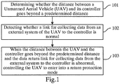
- Fig. 1 is a flowchart showing a method for controlling an UAV according to an exemplary embodiment. The method is performed by an UAV, and may comprise the following steps as shown in Fig. 1 .
- Step 101 it is determined whether a distance between an Unmanned Aerial Vehicle (UAV) and a controller of the UAV goes beyond (i.e. exceeds) human's viewing distance.
- UAV Unmanned Aerial Vehicle
- the controller may be a remote or a mobile terminal.
- the human's viewing distance is a predetermined distance.
- the human's viewing distance may be a default value set by the manufacture when the UAV is delivered.
- the human's viewing distance may also be a user-defined value set by the user using the remote or the mobile terminal during operation.
- Step 102 it is detected whether a link for collecting data from an external system of the UAV is normal.
- the external system is configured to detect a flying environment of the UAV, and the link for collecting data is configured to send data detected by the external system about the flying environment to the controller, so that the user can check the flying environment of the UAV by using the controller.
- the link for collecting data is normal if said link meets at least one predefined criteria: the data from the link for collecting data is receivable; or the handshaking information is acknowledged in time.
- Step 103 when the distance between the UAV and the controller goes beyond the human's viewing distance and the link for collecting data from the external system to the controller is abnormal, the UAV is controlled to enter into a return protection mode.
- the controlling the UAV to enter into a return protection mode comprises any one of: controlling the UAV to fly back to a position where the controller is located; and controlling the UAV to fly back to a predetermined position.
- the predetermined position may be a set of predetermined position coordinates.
- the UAV in such case when the distance between the UAV and the controller goes beyond the human's viewing distance and the link for collecting data from the external system to the controller is abnormal, as it is hard for the users to determine the flying environment of their UAV, the UAV is controlled to enter into a return protection mode. This way the UAV can be protected, thus reducing the possibility of a collision of the UAV with objects surrounding it and improving the UAV safety.
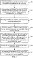
- Fig. 2 is a flow chart showing another method for controlling an UAV according to an exemplary embodiment.
- the method is performed in an UAV, and in this embodiment, the external system may be a camera, an infrared sensor system or a depth-of-field camera (DOF Camera).
- the method may comprise the following steps.
- Step 201 position coordinates of the UAV and position coordinates of the controller are acquired.
- the controller may be a remote or a mobile terminal.
- the step 201 may comprise:
- the positioning systems may comprise at least one of a GPS, a Base Station Positioning System and a Wireless Fidelity Positioning System.
- the position coordinates of the controller may be transmitted through a control channel between the controller and the UAV, which is also the channel for transmitting a control instruction from the controller to the UAV.
- Step 202 the distance between the UAV and the controller is determined according to the position coordinates of the UAV and the position coordinates of the controller.
- the distance between the UAV and the controller may be calculated based on the formula of the distance between two points.
- Step 203 it is decided whether the distance between the UAV and the controller goes beyond the human's viewing distance.
- the human's viewing distance may be a default value set by the manufacture when the UAV is delivered.
- the human's viewing distance may also be a user-defined value set by the user using the remote or the mobile terminal during operation.
- Steps 201-203 it can be decided whether the distance between the UAV and the controller goes beyond the human's viewing distance.
- Step 204 it is detected whether a link for collecting data from an external system of the UAV is normal.
- the external system is configured on the UAV to detect a flying environment of the UAV, and the link for collecting data is configured to send data detected by the external system about the flying environment to the controller, so that the user can check the flying environment of the UAV by using the controller.
- the link for collecting data is independent from the link through which the controller sends the control instruction between the controller and the UAV, so even if the link for collecting data is abnormal, the transmission of the position coordinates of the controller may not be affected.
- the external system may comprise at least one of a camera, an infrared sensor system and a depth-of-field camera.
- the camera will capture images around the UAV.
- the captured images of the camera that is the data about the flying environment
- the mobile terminal of the user via said link, allowing the user to determine accurately the flying environment of the UAV.
- the infrared sensor system or the depth-of-field camera may sense the relative position information between the UAV and the objects surrounding it (that is the data about the flying environment).
- the infrared sensor system or the depth-of-field camera may transmit the sensed relative position information to the mobile terminal of the user.
- Step 204 may comprise:
- Step 205 when the distance between the UAV and the controller goes beyond the human's viewing distance and the link for collecting data from the external system to the controller is abnormal, the UAV is controlled to enter into a return protection mode.
- the controlling the UAV to enter into a return protection mode comprises any one of: controlling the UAV to fly back to a position where the controller is located and controlling the UAV to fly back to a predetermined position.
- the method of this embodiment may further comprise: when the distance between the UAV and the controller goes beyond the human's viewing distance while the link for collecting data from the external system to the controller is normal, or when the distance between the UAV and the controller is within the human's viewing distance (no matter whether the link for collecting data from the external system to the controller is normal or not), the UAV is controlled to fly normally.
- Controlling the UAV to fly normally means giving control over the UAV to the controller, which may comprise:
- the method of this embodiment may further comprise the following steps:
- Steps 201-203 and Step 204 are not limited. Steps 201-203 and Step 204 may be carried out at the same time; or Steps 201-203 may be carried out firstly, and when the distance between the UAV and the controller of the UAV goes beyond the human's viewing distance, step 204 is then carried out; or Step 204 may be carried out firstly, and when the link for collecting data from the external system of the UAV is abnormal, steps 201-203 are then carried out.
- the method may further comprise: when the distance between the UAV and the controller is within the range of the viewing distance while the link for collecting data from the external system is abnormal, the UAV is controlled to fly within the range of the human's viewing distance. At this time, controlling the UAV to fly within the range of the human's viewing distance may further improve the flight safety of the UAV.
- the users can send instructions of forbidding flying beyond the viewing distance to their UAV by operating their controller in some scenarios.
- One scenario is that during the flight of the UAV, when the UAV flies back within the range of the viewing distance, i.e., when the users find their UAV in sight, due to the link for collecting data being abnormal, the users cannot know the flying environment of their UAV.
- Another scenario is when the UAV just takes off (operated by new users).
- the method may further comprise: receiving an instruction of forbidding flying beyond the viewing distance;
- the controlling the UAV to fly within the viewing distance may further comprise:
- the UAV is controlled to enter into a return protection mode. This way the UAV can be protected, thus reducing the possibility of a collision of the UAV whith objects surrounding it and improving the UAV safety.
- Fig. 3 is a structural block diagram of a device for controlling an UAV according to an exemplary embodiment. As shown in Fig. 3 , the device may comprise a determination module 301, a detection module 302 and a controlling module 303.
- the determination module 301 is configured to determine whether a distance between an Unmanned Aerial Vehicle (UAV) and a controller of the UAV goes beyond human's viewing distance.
- UAV Unmanned Aerial Vehicle
- the detection module 302 is configured to detect whether a link for collecting data from an external system of the UAV to the controller is normal.
- the controlling module 303 is configured to, when the distance between the UAV and the controller goes beyond the human's viewing distance and the link for collecting data of the external system to the controller is abnormal, control the UAV to enter into a return protection mode.
- the controller may be a remote or a mobile terminal.
- the human's viewing distance may be a default value set by the manufacture when the UAV is delivered
- the human's viewing distance may also be a user-defined value set by the user using the remote or the mobile terminal during operation.
- the external system is configured to detect a flying environment of the UAV, and the link for collecting data is configured to send data detected by the external system about the flying environment to the controller, so that the user can check the flying environment of the UAV by using the controller.
- the UAV in such case when the distance between the UAV and the controller goes beyond the human's viewing distance and the link for collecting data from the external system to the controller is abnormal, as it is hard for the users to determine the flying environment of their UAV, the UAV is controlled to enter into a return protection mode. This way the UAV can be protected, thus reducing the possibility of a collision of the UAV with objects surrounding it and improving the UAV safety.
- Fig. 4 is a structural block diagram of a device for controlling an UAV according to an exemplary embodiment. As shown in Fig. 4 , the device may comprise a determination module 401, a detection module 402 and a controlling module 403.
- the determination module 401 is configured to determine whether a distance between the Unmanned Aerial Vehicle (UAV) and a controller of the UAV goes beyond human's viewing distance.
- UAV Unmanned Aerial Vehicle
- the detection module 402 is configured to detect whether a link for collecting data from an external system of the UAV to the controller is normal.
- the controlling module 403 is configured to, when the distance between the UAV and the controller goes beyond the human's viewing distance and the link for collecting data from the external system to the controller is abnormal, control the UAV to enter into a return protection mode.
- the controller may be a remote or a mobile terminal.
- the human's viewing distance may be a default value set by the manufacture when the UAV is delivered.
- the human's viewing distance may also be a user-defined value set by the user using the remote or the mobile terminal during operation.
- the external system is configured on the UAV to detect a flying environment of the UAV, and the link for collecting data is configured to send data detected by the external system about the flying environment to the controller, so that the user can check the flying environment of the UAV by using the controller.
- the link for collecting data is independent from the link through which the controller sends the control instruction between the controller and the UAV, so even if the link for collecting data is abnormal, the transmission of the position coordinates of the controller may not be affected.
- the external system may comprise at least one of a camera, an infrared sensor system and a depth-of-field camera.
- the camera will capture images around the UAV.
- the captured images of the camera that is the data about the flying environment
- the link for collecting data is transmitted to the mobile terminal of the user via the link for collecting data, allowing the user to determine accurately the flying environment of the UAV.
- the infrared sensor system or the depth-of-field camera may sense the relative position information between the UAV and the objects surrounding it (that is the data about the flying environment).
- the infrared sensor system or the depth-of-field camera may transmit the sensed relative position information to the mobile terminal of the user.
- controlling module 403 is configured to any one of control the UAV to fly back to a position where the controller is located; and control the UAV to fly back to a predetermined position.
- the determination module 401 comprises an acquisition sub-module 4011, a determination sub-module 4012, and a deciding sub-module 4013.
- the acquisition sub-module 4011 is configured to acquire position coordinates of the UAV and position coordinates of the controller.
- the determination sub-module 4012 is configured to determine the distance between the UAV and the controller according to the position coordinates of the UAV and the position coordinates of the controller acquired by the acquisition sub-module 4011.
- the deciding sub-module 4013 is configured to decide whether the distance determined by the determination sub-module goes beyond the human's viewing distance.
- the acquisition sub-module 4011 is configured to acquire the position coordinates of the UAV using a positioning system of the UAV; receive the position coordinates of the controller sent from the controller, the position coordinates of the controller being acquired by the controller using a positioning system of the controller.
- the positioning system of the UAV and the positioning system of the controller may comprise at least one of a GPS, a Base Station Positioning System and a Wireless Fidelity Positioning System.
- the position coordinates of the controller may be transmitted through a control channel between the controller and the UAV, which is also the channel for transmitting a control instruction sent from the controller to the UAV.
- the device may further comprise: a receiving module 404 configured to receive an instruction of exiting the return protection mode.
- the controlling module 403 is further configured to, in response to the instruction of exiting the return protection mode received by the receiving module 404, transfer control over the UAV to the controller.
- controlling module 403 is further configured to, when the distance between the UAV and the controller goes beyond the human's viewing distance while the link for collecting data from the external system to the controller is normal, or when the distance between the UAV and the controller is within the human's viewing distance (no matter whether the link for collecting data from the external system to the controller is normal or not), control the UAV to fly normally, i.e., give the control over the UAV to the controller, and control the UAV to fly according to the flying instruction of the controller.
- the receiving module 404 is further configured to receive a flying instruction sent from the controller, which may be one or combination of turning left, turning right, diving, speeding up, speeding down and so on.
- controlling module 403 is further configured to control the UAV to fly according to the received flying instruction.
- controlling module 403 is further configured to, when the distance between the UAV and the controller is within the range of the viewing distance while the link for collecting data from the external system to the controller is abnormal, control the UAV to fly within the range of the human's viewing distance. At this time, controlling the UAV to fly within the range of the human's viewing distance may further improve the flight safety of the UAV.
- the users can send instructions of forbidding flying beyond the viewing distance to their UAV by operating their controller in some scenarios.
- One scenario is that during the flight of the UAV, when the UAV flies back within the range of the viewing distance, i.e., when the users find their UAV in sight, due to the link for collecting data being abnormal, the users cannot know the flying environment of their UAV.
- Another scenario is when the UAV just takes off (operated by new users).
- the receiving module is further configured to receive an instruction of forbidding flying beyond the viewing distance; and the controlling module is further configured to, in response to the instruction of forbidding flying beyond the viewing distance, control the UAV to fly within the viewing distance.
- controlling module 403 is further configured to detect the distance between the UAV and the controller, and when the distance between the UAV and the controller reaches the viewing distance, control the UAV to fly toward the controller.
- the UAV in such case when the distance between the UAV and the controller goes beyond the human's viewing distance and the link for collecting data from the external system to the controller is abnormal, as it is hard for the users to determine the flying environment of their UAV, the UAV is controlled to enter into a return protection mode. This way the UAV can be protected, thus reducing the possibility of a collision of the UAV with objects surrounding it and improving the UAV safety.
- modules can each be implemented by hardware, or software, or a combination of hardware and software.
- the modules When implemented in hardware, the modules may be implemented as one or more hardware modules, such as one or more application specific integrated circuits.
- the modules When implemented in software, the modules may be implemented as one or more computer programs that are executed on one or more processors.
- Fig. 5 is a structural block diagram of a device 500 for controlling an UAV according to an exemplary embodiment.
- the device 500 may be an UAV or the like.
- the device 500 may comprise one or more of the following components: a processing component 502, a memory 504, a power supply component 506, a multimedia component 508, an input/output (I/O) interface 512, a sensor component 514, and a communication component 516.
- the processing component 502 typically controls overall operations of the device 500, such as the operations associated with data communications, camera operations, and recording operations.
- the processing component 502 may comprise one or more processors 520 to execute instructions to perform all or part of the steps in the above described methods.
- the processing component 502 may comprise one or more modules which facilitate the interaction between the processing component 502 and other components.
- the processing component 502 may comprise a multimedia module to facilitate the interaction between the multimedia component 508 and the processing component 502.
- the memory 504 is configured to store various types of data to support the operation of the device 500. Examples of such data comprise instructions for any applications or methods operated on the device 500.
- the memory 504 may be implemented using any type of volatile or non-volatile memory devices, or a combination thereof, such as a static random access memory (SRAM), an electrically erasable programmable read-only memory (EEPROM), an erasable programmable read-only memory (EPROM), a programmable read-only memory (PROM), a read-only memory (ROM), a magnetic memory, a flash memory, a magnetic or optical disk.
- SRAM static random access memory
- EEPROM electrically erasable programmable read-only memory
- EPROM erasable programmable read-only memory
- PROM programmable read-only memory
- ROM read-only memory
- magnetic memory a magnetic memory
- flash memory a flash memory
- magnetic or optical disk a magnetic or optical disk.
- the power supply component 506 provides power to various components of the device 500.
- the power supply component 506 may comprise a power management system, one or more power sources, and any other components associated with the generation, management, and distribution of power in the device 500.
- the multimedia component 508 comprises at least one camera.
- the camera may receive external multimedia data.
- Each camera may be a fixed optical lens system or have focal length and optical zoom capability.
- the I/O interface 512 provides an interface between the processing component 502 and peripheral interface modules, such as a keyboard, a click wheel, buttons, and the like.
- the sensor component 514 comprises one or more sensors to provide status assessments of various aspects of the device 500.
- the sensor component 514 may detect an environment in which the device 500 is located.
- the sensor component 514 may comprise an infrared sensor configured to detect distances from the device 500 to objects surrounding the object 500.
- the sensor component 514 may also comprise a light sensor, such as a CMOS or CCD image sensor, for use in imaging applications.
- the sensor component 514 may also comprise an accelerometer sensor, a gyroscope sensor, a magnetic sensor, a pressure sensor, or a temperature sensor.
- the communication component 516 is configured to facilitate communication, wired or wirelessly, between the device 500 and other devices.
- the device 500 can access a wireless network based on a communication standard, such as WiFi, 2G, or 3G, or a combination thereof.
- the communication component 516 receives a broadcast signal or broadcast associated information from an external broadcast management system via a broadcast channel.
- the communication component 516 further comprises a near field communication (NFC) module to facilitate short-range communications.
- the NFC module may be implemented based on a radio frequency identification (RFID) technology, an infrared data association (IrDA) technology, an ultra-wideband (UWB) technology, a Bluetooth (BT) technology, and other technologies.
- RFID radio frequency identification
- IrDA infrared data association
- UWB ultra-wideband
- BT Bluetooth
- the device 500 may be implemented with one or more application specific integrated circuits (ASICs), digital signal processors (DSPs), digital signal processing devices (DSPDs), programmable logic devices (PLDs), field programmable gate arrays (FPGAs), controllers, micro-controllers, microprocessors, or other electronic components, for performing the above described methods.
- ASICs application specific integrated circuits
- DSPs digital signal processors
- DSPDs digital signal processing devices
- PLDs programmable logic devices
- FPGAs field programmable gate arrays
- controllers micro-controllers, microprocessors, or other electronic components, for performing the above described methods.
- non-transitory computer-readable storage medium comprising instructions, such as comprised in the memory 504, executable by the processor 520 in the device 500, for performing the above-described methods.
- the non-transitory computer-readable storage medium may be a ROM, a RAM, a CD-ROM, a magnetic tape, a floppy disc, an optical data storage device, and the like.
- Non-transitory computer readable storage medium storing instructions, executable by a processor of an Unmanned Aerial Vehicle (UAV), enabling the UAV to perform a method for controlling the UAV, comprising:
- the determining whether a distance between an Unmanned Aerial Vehicle (UAV) and the controller of the UAV goes beyond human's viewing distance comprises:
- the acquiring the position coordinates of the UAV and the position coordinates of the controller comprises:
- the human's viewing distance is any one of a default value and a user-defined value.
- the external system comprises at least one of a camera, an infrared sensor system and a depth-of-field camera.
- controlling the UAV to enter into a return protection mode comprises any one of:
- the method further comprises:
Landscapes
- Engineering & Computer Science (AREA)
- Physics & Mathematics (AREA)
- General Physics & Mathematics (AREA)
- Aviation & Aerospace Engineering (AREA)
- Radar, Positioning & Navigation (AREA)
- Remote Sensing (AREA)
- Automation & Control Theory (AREA)
- Computer Networks & Wireless Communication (AREA)
- Control Of Position, Course, Altitude, Or Attitude Of Moving Bodies (AREA)
- Traffic Control Systems (AREA)
- Selective Calling Equipment (AREA)
Claims (15)
- Verfahren zur Steuerung eines unbemannten Luftfahrzeugs (UAV), umfassend:- Bestimmen (101, 203), ob eine Entfernung zwischen dem UAV und einer Steuereinheit des UVA über eine vorher bestimmte Entfernung hinausgeht,- Erfassen (102, 204), ob eine Verbindung zum Senden von Daten, die durch ein externes System des UAV erfasst werden, an die Steuereinheit normal ist, wobei das externe System dazu ausgestaltet ist, eine Flugumgebung des UAV zu erfassen, und- Steuern (103, 205) des UAV, in einen Rückkehrschutzmodus zu gehen,wobei das Verfahren dadurch gekennzeichnet ist, dass das Steuern (103, 205) des UAV, in den Rückkehrschutzmodus zu gehen, durchgeführt wird, wenn die Entfernung zwischen dem UAV und der Steuereinheit über die vorher bestimmte Entfernung hinausgeht und die Verbindung zum Senden von Daten, die von dem externen System erfasst werden, an die Steuereinheit anormal ist.
- Verfahren nach Anspruch 1, wobei das Bestimmen (101, 203), ob eine Entfernung zwischen dem unbemannten Luftfahrzeug (UAV) und der Steuereinheit des UVA über die vorher bestimmte Entfernung hinausgeht, umfasst:- Erlangen (201) von Positionskoordinaten des UAV und Positionskoordinaten der Steuereinheit,- Bestimmen (202) der Entfernung zwischen dem UAV und der Steuereinheit gemäß den Positionskoordinaten des UAV und den Positionskoordinaten der Steuereinheit und- Entscheiden (203), ob die Entfernung zwischen dem UAV und der Steuereinheit über die vorher bestimmte Entfernung hinausgeht.
- Verfahren nach Anspruch 2, wobei das Erlangen (201) der Positionskoordinaten des UAV und der Positionskoordinaten der Steuereinheit umfasst:- Erlangen der Positionskoordinaten des UAV unter Verwendung eines Positionierungssystems des UAV und- Empfangen der Positionskoordinaten der Steuereinheit, die von der Steuereinheit gesendet werden, wobei die Positionskoordinaten der Steuereinheit durch die Steuereinheit unter Verwendung eines Positionierungssystems der Steuereinheit erlangt werden,wobei das Positionierungssystem des UAV und das Positionierungssystem der Steuereinheit mindestens eines von einem GPS, einem Basisstation-Positionierungssystem und einem Wireless-Fidelity-Positionierungssystem umfassen.
- Verfahren nach einem der Ansprüche 1 bis 3, wobei die vorher bestimmte Entfernung ein beliebiger von einem Standardwert und einem benutzerdefinierten Wert ist.
- Verfahren nach einem der Ansprüche 1 bis 4, wobei das externe System mindestens eine bzw. eines von einer Kamera, einem Infrarot-Sensorsystem und einer Tiefenschärfekamera umfasst.
- Verfahren nach einem der Ansprüche 1 bis 5, wobei das Steuern (103, 205) des UAV, in den Rückkehrschutzmodus zu gehen, ein beliebiges umfasst von:- Steuern des UAV, zu einer Position, an der sich die Steuereinheit befindet, zurückzufliegen, und- Steuern des UAV, zu einer vorher bestimmten Position zurückzufliegen.
- Verfahren nach einem der Ansprüche 1 bis 6, ferner umfassend:- Empfangen einer Anweisung, den Rückkehrschutzmodus zu verlassen, und- als Reaktion auf die Anweisung, den Rückkehrschutzmodus zu verlassen, Übertragen der Kontrolle über das UAV an die Steuereinheit.
- Vorrichtung zur Steuerung eines unbemannten Luftfahrzeugs (UAV), umfassend:- ein Bestimmungsmodul (301), das dazu ausgestaltet ist, zu bestimmen, ob eine Entfernung zwischen dem UAV und einer Steuereinheit des UVA über eine vorher bestimmte Entfernung hinausgeht,- ein Erfassungsmodul (302), das dazu ausgestaltet ist, zu erfassen, ob eine Verbindung zum Senden von Daten, die durch ein externes System des UAV erfasst werden, an die Steuereinheit normal ist, wobei das externe System dazu ausgestaltet ist, eine Flugumgebung des UAV zu erfassen, und- ein Steuermodul (303), das dazu ausgestaltet ist, das UAV zu steuern, in einen Rückkehrschutzmodus zu gehen,wobei die Vorrichtung dadurch gekennzeichnet ist, dass das Steuermodul (303) dazu ausgestaltet ist, das UAV zu steuern, in den Rückkehrschutzmodus zu gehen, wenn die Entfernung zwischen dem UAV und der Steuereinheit über die vorher bestimmte Entfernung hinausgeht und die Verbindung zum Senden von Daten, die von dem externen System erfasst werden, an die Steuereinheit anormal ist.
- Vorrichtung nach Anspruch 8, wobei das Bestimmungsmodul (301) umfasst:- ein Erlangungsteilmodul (4011), das dazu ausgestaltet ist, Positionskoordinaten des UAV und Positionskoordinaten der Steuereinheit zu erlangen,- ein Bestimmungsteilmodul (4012), das dazu ausgestaltet ist, die Entfernung zwischen dem UAV und der Steuereinheit gemäß den Positionskoordinaten des UAV und den Positionskoordinaten der Steuereinheit, die von dem Erlangungsteilmodul erlangt werden, zu bestimmen, und- ein Entscheidungsteilmodul (4012), das dazu ausgestaltet ist zu entscheiden, ob die Entfernung zwischen dem UAV und der Steuereinheit, die von dem Bestimmungsteilmodul bestimmt wurde, über die vorher bestimmte Entfernung hinausgeht.
- Vorrichtung nach Anspruch 9, wobei das Erlangungsteilmodul (4011) ausgestaltet ist zum:- Erlangen der Positionskoordinaten des UAV unter Verwendung eines Positionierungssystems des UAV,- Empfangen der Positionskoordinaten der Steuereinheit, die von der Steuereinheit gesendet werden, wobei die Positionskoordinaten der Steuereinheit durch die Steuereinheit unter Verwendung eines Positionierungssystems der Steuereinheit erlangt werden,wobei das Positionierungssystem des UAV und das Positionierungssystem der Steuereinheit mindestens eines von einem GPS, einem Basisstation-Positionierungssystem und einem Wireless-Fidelity-Positionierungssystem umfassen.
- Vorrichtung nach einem der Ansprüche 8 bis 10, wobei die vorher bestimmte Entfernung ein beliebiger von einem Standardwert und einem benutzerdefinierten Wert ist.
- Vorrichtung nach einem der Ansprüche 8 bis 11, wobei das externe System mindestens eine bzw. eines von einer Kamera, einem Infrarot-Sensorsystem und einer Tiefenschärfekamera umfasst.
- Vorrichtung nach einem der Ansprüche 8 bis 12, wobei das Steuermodul zu mindestens einem von Steuern des UAV, zu einer Position, an der sich die Steuereinheit befindet, zurückzufliegen, und Steuern des UAV, zu einer vorher bestimmten Position zurückzufliegen, ausgestaltet ist.
- Vorrichtung nach einem der Ansprüche 8 bis 13, ferner umfassend:- ein Empfangsmodul (404), das dazu ausgestaltet ist, eine Anweisung zum Verlassen des Rückkehrschutzmodus zu empfangen, wobei das Steuermodul dazu ausgestaltet ist, als Reaktion auf die Anweisung zum Verlassen des Rückkehrschutzmodus die Kontrolle über das UAV an die Steuereinheit zu übertragen.
- Computerprogramm, das Anweisungen zum Ausführen des Schritts eines Verfahrens nach einem der Ansprüche 1 bis 7, wenn das Programm von einem Computer ausgeführt wird, beinhaltet.
Applications Claiming Priority (1)
| Application Number | Priority Date | Filing Date | Title |
|---|---|---|---|
| CN201510727596.XA CN105278544B (zh) | 2015-10-30 | 2015-10-30 | 无人飞行器的控制方法及装置 |
Publications (2)
| Publication Number | Publication Date |
|---|---|
| EP3163394A1 EP3163394A1 (de) | 2017-05-03 |
| EP3163394B1 true EP3163394B1 (de) | 2020-02-12 |
Family
ID=55147722
Family Applications (1)
| Application Number | Title | Priority Date | Filing Date |
|---|---|---|---|
| EP16175431.2A Active EP3163394B1 (de) | 2015-10-30 | 2016-06-21 | Verfahren und vorrichtung zur steuerung eines unbemannten luftfahrzeugs |
Country Status (8)
| Country | Link |
|---|---|
| US (1) | US20170123413A1 (de) |
| EP (1) | EP3163394B1 (de) |
| JP (1) | JP6400225B2 (de) |
| KR (1) | KR20170061624A (de) |
| CN (1) | CN105278544B (de) |
| MX (1) | MX368890B (de) |
| RU (1) | RU2637838C2 (de) |
| WO (1) | WO2017071044A1 (de) |
Families Citing this family (34)
| Publication number | Priority date | Publication date | Assignee | Title |
|---|---|---|---|---|
| US20170151969A1 (en) | 2015-12-01 | 2017-06-01 | Laird Technologies, Inc. | Systems and methods for safety locking of operator control units for remote control machines |
| EP3399380B1 (de) * | 2015-12-31 | 2021-12-29 | Powervision Robot Inc. | Steuerverfahren headless |
| EP3438775A1 (de) * | 2016-03-31 | 2019-02-06 | Nikon Corporation | Flugvorrichtung, elektronische vorrichtung und programm |
| US10059446B2 (en) * | 2016-06-06 | 2018-08-28 | Traxxas Lp | Ground vehicle-like control for remote control aircraft |
| CN106200675A (zh) * | 2016-08-17 | 2016-12-07 | 邹霞 | 基于dsp模块化小型无人机自驾仪 |
| WO2018032433A1 (zh) * | 2016-08-17 | 2018-02-22 | 邹霞 | 基于dsp模块化小型无人机自驾仪 |
| CN106454069B (zh) * | 2016-08-31 | 2019-11-08 | 歌尔股份有限公司 | 一种控制无人机拍摄的方法、装置和可穿戴设备 |
| WO2018133064A1 (zh) * | 2017-01-22 | 2018-07-26 | 深圳市大疆创新科技有限公司 | 可移动装置的控制方法、控制系统、和可移动装置 |
| JP7088953B2 (ja) | 2017-03-21 | 2022-06-21 | エスゼット ディージェイアイ テクノロジー カンパニー リミテッド | 無人航空機(uav)を監視する方法、システム、プログラム、及び記録媒体 |
| WO2018178751A1 (en) | 2017-03-31 | 2018-10-04 | Telefonaktiebolaget Lm Ericsson (Publ) | Broadcasting geolocation information in a radio frame transmitted from an unmanned aerial vehicle |
| WO2018178759A1 (en) | 2017-03-31 | 2018-10-04 | Telefonaktiebolaget Lm Ericsson (Publ) | Enhanced flight plan for unmanned traffic aircraft systems |
| CN110663074B (zh) | 2017-03-31 | 2022-06-10 | 瑞典爱立信有限公司 | 用于在无人航空器系统交通管理框架中使用网络位置服务的方法和系统 |
| EP3610346A1 (de) | 2017-04-14 | 2020-02-19 | Telefonaktiebolaget LM Ericsson (Publ) | Optimale unbemannte luftfahrzeugflugroutenplanung basierend auf den dienstgüteanforderungen für daten-, telemetrie und befehls- und steuerungsanforderungen in 3gpp-netzwerken |
| CN110800221B (zh) | 2017-05-05 | 2022-04-08 | 瑞典爱立信有限公司 | 用于管理无人航空载具的方法、装置和介质 |
| WO2019012308A1 (en) | 2017-07-10 | 2019-01-17 | Telefonaktiebolaget Lm Ericsson (Publ) | RADIO RESOURCE ASSIGNMENT OPTIMIZATION BASED ON AIRCRAFT FLIGHT FLIGHT INFORMATION WITHOUT CREW |
| CN107272724A (zh) * | 2017-08-04 | 2017-10-20 | 南京华捷艾米软件科技有限公司 | 一种体感飞行装置及其控制方法 |
| CN107505857A (zh) * | 2017-08-07 | 2017-12-22 | 广州南洋理工职业学院 | 飞行器应急控制方法和设备 |
| CN107703934A (zh) * | 2017-08-24 | 2018-02-16 | 北京臻迪科技股份有限公司 | 一种无人船的控制方法及装置 |
| EP3679741A1 (de) | 2017-09-05 | 2020-07-15 | Telefonaktiebolaget LM Ericsson (PUBL) | Geplante kontinuität der verbindungskonnektivität eines unbemannten luftfahrzeugs (uav) in uav-verkehrsmanagementsystemen |
| CN107885227A (zh) * | 2017-11-30 | 2018-04-06 | 广州市华科尔科技股份有限公司 | 一种无人机自动避障方法 |
| WO2019130050A1 (en) | 2017-12-29 | 2019-07-04 | Telefonaktiebolaget Lm Ericsson (Publ) | Using a cellular interface for unmanned aerial vehicle communications |
| CN108594842A (zh) * | 2018-02-01 | 2018-09-28 | 杭州瓦屋科技有限公司 | 无人机步进控制方法及装置 |
| WO2019186245A1 (en) | 2018-03-30 | 2019-10-03 | Telefonaktiebolaget Lm Ericsson (Publ) | Network coverage and policy information generation and distribution for unmanned aerial vehicle flight planning |
| WO2019218325A1 (zh) | 2018-05-17 | 2019-11-21 | 北京小米移动软件有限公司 | 控制无人机接入网络的方法和装置 |
| RU2695215C1 (ru) * | 2018-09-14 | 2019-07-22 | Акционерное общество "Корпорация "Тактическое ракетное вооружение" | Способ проведения испытаний ограничителя системы ликвидации беспилотного летательного аппарата и устройство для его осуществления |
| CN109814569B (zh) * | 2019-02-19 | 2022-11-08 | 阿波罗智能技术(北京)有限公司 | 无人车控制方法、装置、设备及计算机可读介质 |
| CN109765902B (zh) | 2019-02-22 | 2022-10-11 | 阿波罗智能技术(北京)有限公司 | 无人车驾驶参考线处理方法、装置及车辆 |
| CN113034872A (zh) * | 2019-12-25 | 2021-06-25 | 海鹰航空通用装备有限责任公司 | 无人机链路数据传输方法和装置 |
| CN112666970A (zh) * | 2020-12-14 | 2021-04-16 | 广州极飞科技有限公司 | 无人设备控制方法及相关装置 |
| CN114355966A (zh) * | 2021-01-12 | 2022-04-15 | 深圳市慧明捷科技有限公司 | 轻便无人机飞手定位指挥系统 |
| CN114924132A (zh) * | 2022-03-10 | 2022-08-19 | 中国航空工业集团公司沈阳飞机设计研究所 | 一种无人机电磁兼容性测量装置及其方法 |
| US12080058B2 (en) * | 2022-09-06 | 2024-09-03 | University Of Electronic Science And Technology Of China | System for real-time target identification of unmanned aerial vehicle based on embedded technique and improved YOLO4 algorithm |
| US12552559B2 (en) | 2022-09-21 | 2026-02-17 | T-Mobile Usa, Inc. | Antenna measurement using unmanned aerial vehicles |
| DE102024102069A1 (de) * | 2024-01-24 | 2025-07-24 | E.On Se | Verfahren und Vorrichtung zum Steuern einer Drohne zum Inspizieren von linearer Infrastruktur |
Family Cites Families (39)
| Publication number | Priority date | Publication date | Assignee | Title |
|---|---|---|---|---|
| US5890441A (en) * | 1995-09-07 | 1999-04-06 | Swinson Johnny | Horizontal and vertical take off and landing unmanned aerial vehicle |
| US6460810B2 (en) * | 1996-09-06 | 2002-10-08 | Terry Jack James | Semiautonomous flight director |
| DE19849857C2 (de) * | 1998-10-29 | 2003-08-21 | Eads Deutschland Gmbh | Fernlenkverfahren für ein unbemanntes Luftfahrzeug |
| US7231294B2 (en) * | 2003-10-23 | 2007-06-12 | International Business Machines Corporation | Navigating a UAV |
| WO2005076967A2 (en) * | 2004-02-06 | 2005-08-25 | Icosystem Corporation | Methods and systems for area search using a plurality of unmanned vehicles |
| JP3939710B2 (ja) * | 2004-06-04 | 2007-07-04 | コデン株式会社 | 遠隔操縦無人ボート |
| US7818127B1 (en) * | 2004-06-18 | 2010-10-19 | Geneva Aerospace, Inc. | Collision avoidance for vehicle control systems |
| US7512462B2 (en) * | 2004-11-16 | 2009-03-31 | Northrop Grumman Corporation | Automatic contingency generator |
| FR2894368B1 (fr) * | 2005-12-07 | 2008-01-25 | Thales Sa | Dispositif et procede de construction automatisee de trajectoire d'urgence pour aeronefs |
| US7778744B2 (en) * | 2006-04-20 | 2010-08-17 | Honeywell International Inc. | Avionics framework |
| RU2320519C1 (ru) * | 2006-09-27 | 2008-03-27 | Центральный научно-исследовательский и опытно-конструкторский институт робототехники и кибернетики (ЦНИИ РТК) | Портативный комплекс воздушного базирования оптико-визуального мониторинга |
| CN102475977A (zh) * | 2010-11-26 | 2012-05-30 | 东莞龙昌数码科技有限公司 | 一种飞行器玩具 |
| CN102156481B (zh) * | 2011-01-24 | 2013-06-05 | 广州嘉崎智能科技有限公司 | 无人飞行器的智能追踪控制方法及系统 |
| WO2013074843A1 (en) * | 2011-11-15 | 2013-05-23 | Insitu, Inc. | Controlled range and payload for unmanned vehicles, and associated systems and methods |
| DE102012002067A1 (de) * | 2012-02-03 | 2013-08-08 | Eads Deutschland Gmbh | Luft-Boden-Überwachungs- und/oder Wirksystem und Verfahren zur luftgestützten Inspektion und/oder Bekämpfung von auf dem Land oder auf See befindlichen Objekten |
| CN102955478B (zh) * | 2012-10-24 | 2016-01-20 | 深圳一电科技有限公司 | 无人机飞行控制方法及系统 |
| CN102999049B (zh) * | 2012-11-09 | 2016-04-27 | 国家电网公司 | 一种无线遥控架空线路巡检飞行器 |
| US8798922B2 (en) * | 2012-11-16 | 2014-08-05 | The Boeing Company | Determination of flight path for unmanned aircraft in event of in-flight contingency |
| EP2733560A1 (de) * | 2012-11-19 | 2014-05-21 | The Boeing Company | Autonome Missionsverwaltung |
| US9375847B2 (en) * | 2013-01-18 | 2016-06-28 | Irobot Corporation | Environmental management systems including mobile robots and methods using same |
| US9233472B2 (en) * | 2013-01-18 | 2016-01-12 | Irobot Corporation | Mobile robot providing environmental mapping for household environmental control |
| US20160247115A1 (en) * | 2013-07-02 | 2016-08-25 | Jasper Mason PONS | Airborne scanning system and method |
| CN105247593B (zh) * | 2014-04-17 | 2017-04-19 | 深圳市大疆创新科技有限公司 | 飞行禁区的飞行控制 |
| US9688403B2 (en) * | 2014-05-20 | 2017-06-27 | Infatics, Inc. | Method for adaptive mission execution on an unmanned aerial vehicle |
| CN106573684B (zh) * | 2014-08-08 | 2019-05-21 | 深圳市大疆创新科技有限公司 | 多区的电池更换系统 |
| JP2017527059A (ja) * | 2014-08-29 | 2017-09-14 | ズーナム エアロ,インコーポレイテッド | ハイブリッド電動飛行機を使用する地域航空交通網を実施するためのシステム及び方法 |
| US20160116912A1 (en) * | 2014-09-17 | 2016-04-28 | Youval Nehmadi | System and method for controlling unmanned vehicles |
| FR3028186A1 (fr) * | 2014-11-12 | 2016-05-13 | Parrot | Equipement de telecommande de drone a longue portee |
| US9919797B2 (en) * | 2014-12-04 | 2018-03-20 | Elwha Llc | System and method for operation and management of reconfigurable unmanned aircraft |
| US9752878B2 (en) * | 2014-12-09 | 2017-09-05 | Sikorsky Aircraft Corporation | Unmanned aerial vehicle control handover planning |
| CN104516354A (zh) * | 2014-12-25 | 2015-04-15 | 中国人民解放军总参谋部第六十研究所 | 一种无人直升机电力巡线智能返航路径控制方法 |
| CN104656482A (zh) * | 2015-02-03 | 2015-05-27 | 昆山优力电能运动科技有限公司 | 终端遥控装置 |
| CN204452931U (zh) * | 2015-02-14 | 2015-07-08 | 广东澄星航模科技股份有限公司 | 一种跟随四轴飞行器 |
| CN104714556B (zh) * | 2015-03-26 | 2017-08-11 | 清华大学 | 无人机智能航向控制方法 |
| CN107409051B (zh) * | 2015-03-31 | 2021-02-26 | 深圳市大疆创新科技有限公司 | 用于生成飞行管制的认证系统和方法 |
| CN104881041B (zh) * | 2015-05-27 | 2017-11-07 | 深圳市高巨创新科技开发有限公司 | 一种无人飞行器的电量预警方法及装置 |
| CN104898699B (zh) * | 2015-05-28 | 2020-03-17 | 小米科技有限责任公司 | 飞行控制方法及装置、电子设备 |
| US9715235B2 (en) * | 2015-06-05 | 2017-07-25 | The Boeing Company | Autonomous unmanned aerial vehicle decision-making |
| JP6682379B2 (ja) * | 2015-08-06 | 2020-04-15 | パナソニック インテレクチュアル プロパティ コーポレーション オブ アメリカPanasonic Intellectual Property Corporation of America | 無人飛行体、飛行制御方法、飛行制御プログラム及び操縦器 |
-
2015
- 2015-10-30 CN CN201510727596.XA patent/CN105278544B/zh active Active
- 2015-12-25 KR KR1020167003967A patent/KR20170061624A/ko not_active Ceased
- 2015-12-25 RU RU2016114286A patent/RU2637838C2/ru active
- 2015-12-25 WO PCT/CN2015/098844 patent/WO2017071044A1/zh not_active Ceased
- 2015-12-25 JP JP2017547040A patent/JP6400225B2/ja active Active
- 2015-12-25 MX MX2016004627A patent/MX368890B/es active IP Right Grant
-
2016
- 2016-05-26 US US15/166,138 patent/US20170123413A1/en not_active Abandoned
- 2016-06-21 EP EP16175431.2A patent/EP3163394B1/de active Active
Non-Patent Citations (1)
| Title |
|---|
| None * |
Also Published As
| Publication number | Publication date |
|---|---|
| RU2637838C2 (ru) | 2017-12-07 |
| MX2016004627A (es) | 2017-08-09 |
| WO2017071044A1 (zh) | 2017-05-04 |
| KR20170061624A (ko) | 2017-06-05 |
| RU2016114286A (ru) | 2017-10-16 |
| CN105278544B (zh) | 2018-05-08 |
| JP6400225B2 (ja) | 2018-10-03 |
| CN105278544A (zh) | 2016-01-27 |
| US20170123413A1 (en) | 2017-05-04 |
| MX368890B (es) | 2019-10-21 |
| EP3163394A1 (de) | 2017-05-03 |
| JP2017539040A (ja) | 2017-12-28 |
Similar Documents
| Publication | Publication Date | Title |
|---|---|---|
| EP3163394A1 (de) | Verfahren und vorrichtung zur steuerung eines unbemannten luftfahrzeugs | |
| US10569874B2 (en) | Flight control method and apparatus | |
| US20190253626A1 (en) | Target tracking method and aircraft | |
| US20250102323A1 (en) | Method, device and system for processing a flight task | |
| RU2759064C1 (ru) | Способ и устройство для сообщения маршрутной информации полета и способ и устройство для определения информации | |
| US20160140778A1 (en) | Method and system for identifying damage caused to a vehicle | |
| US11815913B2 (en) | Mutual recognition method between unmanned aerial vehicle and wireless terminal | |
| US20140327791A1 (en) | Imaging systems, moving bodies, and imaging control methods for remote monitoring of a moving target | |
| US20180088596A1 (en) | Method, apparatus and system for controlling unmanned aerial vehicle | |
| US9977429B2 (en) | Methods and systems for positioning a camera in an incident area | |
| US12067782B2 (en) | Surveillance camera system and method for operating same | |
| KR101883292B1 (ko) | 재난 구조 및 대응 시스템 및 그 운용 방법 | |
| US20200180759A1 (en) | Imaging device, camera-equipped drone, and mode control method, and program | |
| CN109218598B (zh) | 一种相机切换方法、装置及无人机 | |
| KR102267615B1 (ko) | 임무 장비 교체 가능한 무인기 및 공통플랫폼 시스템 | |
| US12519910B2 (en) | Information processing device and method for controlling image data thereof | |
| US12348860B2 (en) | Robot sensor data management | |
| US20200241572A1 (en) | Drone control method and device, drone and core network device | |
| US11431255B2 (en) | Analysis system, analysis method, and program storage medium | |
| EP3919374B1 (de) | Bilderfassungsverfahren | |
| US11092959B2 (en) | Method and apparatus for data transmission | |
| JP6954858B2 (ja) | 飛行管理システム及び飛行装置 | |
| KR20170031939A (ko) | Cctv 대용 드론을 포함하는 cctv 관제 시스템, 이를 이용한 영상 관제 방법 | |
| JP6992365B2 (ja) | 端末装置、カメラシステムおよび制御方法 | |
| CN120578096A (zh) | 遥控泊车方法、装置、车辆、设备、存储介质及程序产品 |
Legal Events
| Date | Code | Title | Description |
|---|---|---|---|
| PUAI | Public reference made under article 153(3) epc to a published international application that has entered the european phase |
Free format text: ORIGINAL CODE: 0009012 |
|
| STAA | Information on the status of an ep patent application or granted ep patent |
Free format text: STATUS: THE APPLICATION HAS BEEN PUBLISHED |
|
| AK | Designated contracting states |
Kind code of ref document: A1 Designated state(s): AL AT BE BG CH CY CZ DE DK EE ES FI FR GB GR HR HU IE IS IT LI LT LU LV MC MK MT NL NO PL PT RO RS SE SI SK SM TR |
|
| AX | Request for extension of the european patent |
Extension state: BA ME |
|
| STAA | Information on the status of an ep patent application or granted ep patent |
Free format text: STATUS: REQUEST FOR EXAMINATION WAS MADE |
|
| 17P | Request for examination filed |
Effective date: 20170929 |
|
| RBV | Designated contracting states (corrected) |
Designated state(s): AL AT BE BG CH CY CZ DE DK EE ES FI FR GB GR HR HU IE IS IT LI LT LU LV MC MK MT NL NO PL PT RO RS SE SI SK SM TR |
|
| GRAP | Despatch of communication of intention to grant a patent |
Free format text: ORIGINAL CODE: EPIDOSNIGR1 |
|
| STAA | Information on the status of an ep patent application or granted ep patent |
Free format text: STATUS: GRANT OF PATENT IS INTENDED |
|
| INTG | Intention to grant announced |
Effective date: 20190927 |
|
| GRAS | Grant fee paid |
Free format text: ORIGINAL CODE: EPIDOSNIGR3 |
|
| GRAA | (expected) grant |
Free format text: ORIGINAL CODE: 0009210 |
|
| STAA | Information on the status of an ep patent application or granted ep patent |
Free format text: STATUS: THE PATENT HAS BEEN GRANTED |
|
| AK | Designated contracting states |
Kind code of ref document: B1 Designated state(s): AL AT BE BG CH CY CZ DE DK EE ES FI FR GB GR HR HU IE IS IT LI LT LU LV MC MK MT NL NO PL PT RO RS SE SI SK SM TR |
|
| REG | Reference to a national code |
Ref country code: GB Ref legal event code: FG4D |
|
| REG | Reference to a national code |
Ref country code: CH Ref legal event code: EP |
|
| REG | Reference to a national code |
Ref country code: AT Ref legal event code: REF Ref document number: 1232964 Country of ref document: AT Kind code of ref document: T Effective date: 20200215 |
|
| REG | Reference to a national code |
Ref country code: IE Ref legal event code: FG4D |
|
| REG | Reference to a national code |
Ref country code: DE Ref legal event code: R096 Ref document number: 602016029380 Country of ref document: DE |
|
| PG25 | Lapsed in a contracting state [announced via postgrant information from national office to epo] |
Ref country code: RS Free format text: LAPSE BECAUSE OF FAILURE TO SUBMIT A TRANSLATION OF THE DESCRIPTION OR TO PAY THE FEE WITHIN THE PRESCRIBED TIME-LIMIT Effective date: 20200212 Ref country code: NO Free format text: LAPSE BECAUSE OF FAILURE TO SUBMIT A TRANSLATION OF THE DESCRIPTION OR TO PAY THE FEE WITHIN THE PRESCRIBED TIME-LIMIT Effective date: 20200512 Ref country code: FI Free format text: LAPSE BECAUSE OF FAILURE TO SUBMIT A TRANSLATION OF THE DESCRIPTION OR TO PAY THE FEE WITHIN THE PRESCRIBED TIME-LIMIT Effective date: 20200212 |
|
| REG | Reference to a national code |
Ref country code: LT Ref legal event code: MG4D |
|
| REG | Reference to a national code |
Ref country code: NL Ref legal event code: MP Effective date: 20200212 |
|
| PG25 | Lapsed in a contracting state [announced via postgrant information from national office to epo] |
Ref country code: LV Free format text: LAPSE BECAUSE OF FAILURE TO SUBMIT A TRANSLATION OF THE DESCRIPTION OR TO PAY THE FEE WITHIN THE PRESCRIBED TIME-LIMIT Effective date: 20200212 Ref country code: SE Free format text: LAPSE BECAUSE OF FAILURE TO SUBMIT A TRANSLATION OF THE DESCRIPTION OR TO PAY THE FEE WITHIN THE PRESCRIBED TIME-LIMIT Effective date: 20200212 Ref country code: GR Free format text: LAPSE BECAUSE OF FAILURE TO SUBMIT A TRANSLATION OF THE DESCRIPTION OR TO PAY THE FEE WITHIN THE PRESCRIBED TIME-LIMIT Effective date: 20200513 Ref country code: HR Free format text: LAPSE BECAUSE OF FAILURE TO SUBMIT A TRANSLATION OF THE DESCRIPTION OR TO PAY THE FEE WITHIN THE PRESCRIBED TIME-LIMIT Effective date: 20200212 Ref country code: IS Free format text: LAPSE BECAUSE OF FAILURE TO SUBMIT A TRANSLATION OF THE DESCRIPTION OR TO PAY THE FEE WITHIN THE PRESCRIBED TIME-LIMIT Effective date: 20200612 Ref country code: BG Free format text: LAPSE BECAUSE OF FAILURE TO SUBMIT A TRANSLATION OF THE DESCRIPTION OR TO PAY THE FEE WITHIN THE PRESCRIBED TIME-LIMIT Effective date: 20200512 |
|
| PG25 | Lapsed in a contracting state [announced via postgrant information from national office to epo] |
Ref country code: NL Free format text: LAPSE BECAUSE OF FAILURE TO SUBMIT A TRANSLATION OF THE DESCRIPTION OR TO PAY THE FEE WITHIN THE PRESCRIBED TIME-LIMIT Effective date: 20200212 |
|
| PG25 | Lapsed in a contracting state [announced via postgrant information from national office to epo] |
Ref country code: SK Free format text: LAPSE BECAUSE OF FAILURE TO SUBMIT A TRANSLATION OF THE DESCRIPTION OR TO PAY THE FEE WITHIN THE PRESCRIBED TIME-LIMIT Effective date: 20200212 Ref country code: RO Free format text: LAPSE BECAUSE OF FAILURE TO SUBMIT A TRANSLATION OF THE DESCRIPTION OR TO PAY THE FEE WITHIN THE PRESCRIBED TIME-LIMIT Effective date: 20200212 Ref country code: SM Free format text: LAPSE BECAUSE OF FAILURE TO SUBMIT A TRANSLATION OF THE DESCRIPTION OR TO PAY THE FEE WITHIN THE PRESCRIBED TIME-LIMIT Effective date: 20200212 Ref country code: LT Free format text: LAPSE BECAUSE OF FAILURE TO SUBMIT A TRANSLATION OF THE DESCRIPTION OR TO PAY THE FEE WITHIN THE PRESCRIBED TIME-LIMIT Effective date: 20200212 Ref country code: CZ Free format text: LAPSE BECAUSE OF FAILURE TO SUBMIT A TRANSLATION OF THE DESCRIPTION OR TO PAY THE FEE WITHIN THE PRESCRIBED TIME-LIMIT Effective date: 20200212 Ref country code: ES Free format text: LAPSE BECAUSE OF FAILURE TO SUBMIT A TRANSLATION OF THE DESCRIPTION OR TO PAY THE FEE WITHIN THE PRESCRIBED TIME-LIMIT Effective date: 20200212 Ref country code: PT Free format text: LAPSE BECAUSE OF FAILURE TO SUBMIT A TRANSLATION OF THE DESCRIPTION OR TO PAY THE FEE WITHIN THE PRESCRIBED TIME-LIMIT Effective date: 20200705 Ref country code: EE Free format text: LAPSE BECAUSE OF FAILURE TO SUBMIT A TRANSLATION OF THE DESCRIPTION OR TO PAY THE FEE WITHIN THE PRESCRIBED TIME-LIMIT Effective date: 20200212 Ref country code: DK Free format text: LAPSE BECAUSE OF FAILURE TO SUBMIT A TRANSLATION OF THE DESCRIPTION OR TO PAY THE FEE WITHIN THE PRESCRIBED TIME-LIMIT Effective date: 20200212 |
|
| REG | Reference to a national code |
Ref country code: DE Ref legal event code: R097 Ref document number: 602016029380 Country of ref document: DE |
|
| REG | Reference to a national code |
Ref country code: AT Ref legal event code: MK05 Ref document number: 1232964 Country of ref document: AT Kind code of ref document: T Effective date: 20200212 |
|
| PLBE | No opposition filed within time limit |
Free format text: ORIGINAL CODE: 0009261 |
|
| STAA | Information on the status of an ep patent application or granted ep patent |
Free format text: STATUS: NO OPPOSITION FILED WITHIN TIME LIMIT |
|
| 26N | No opposition filed |
Effective date: 20201113 |
|
| PG25 | Lapsed in a contracting state [announced via postgrant information from national office to epo] |
Ref country code: AT Free format text: LAPSE BECAUSE OF FAILURE TO SUBMIT A TRANSLATION OF THE DESCRIPTION OR TO PAY THE FEE WITHIN THE PRESCRIBED TIME-LIMIT Effective date: 20200212 Ref country code: MC Free format text: LAPSE BECAUSE OF FAILURE TO SUBMIT A TRANSLATION OF THE DESCRIPTION OR TO PAY THE FEE WITHIN THE PRESCRIBED TIME-LIMIT Effective date: 20200212 Ref country code: IT Free format text: LAPSE BECAUSE OF FAILURE TO SUBMIT A TRANSLATION OF THE DESCRIPTION OR TO PAY THE FEE WITHIN THE PRESCRIBED TIME-LIMIT Effective date: 20200212 |
|
| REG | Reference to a national code |
Ref country code: CH Ref legal event code: PL |
|
| PG25 | Lapsed in a contracting state [announced via postgrant information from national office to epo] |
Ref country code: SI Free format text: LAPSE BECAUSE OF FAILURE TO SUBMIT A TRANSLATION OF THE DESCRIPTION OR TO PAY THE FEE WITHIN THE PRESCRIBED TIME-LIMIT Effective date: 20200212 Ref country code: PL Free format text: LAPSE BECAUSE OF FAILURE TO SUBMIT A TRANSLATION OF THE DESCRIPTION OR TO PAY THE FEE WITHIN THE PRESCRIBED TIME-LIMIT Effective date: 20200212 |
|
| PG25 | Lapsed in a contracting state [announced via postgrant information from national office to epo] |
Ref country code: LU Free format text: LAPSE BECAUSE OF NON-PAYMENT OF DUE FEES Effective date: 20200621 |
|
| REG | Reference to a national code |
Ref country code: BE Ref legal event code: MM Effective date: 20200630 |
|
| PG25 | Lapsed in a contracting state [announced via postgrant information from national office to epo] |
Ref country code: IE Free format text: LAPSE BECAUSE OF NON-PAYMENT OF DUE FEES Effective date: 20200621 Ref country code: LI Free format text: LAPSE BECAUSE OF NON-PAYMENT OF DUE FEES Effective date: 20200630 Ref country code: CH Free format text: LAPSE BECAUSE OF NON-PAYMENT OF DUE FEES Effective date: 20200630 |
|
| PG25 | Lapsed in a contracting state [announced via postgrant information from national office to epo] |
Ref country code: BE Free format text: LAPSE BECAUSE OF NON-PAYMENT OF DUE FEES Effective date: 20200630 |
|
| PG25 | Lapsed in a contracting state [announced via postgrant information from national office to epo] |
Ref country code: TR Free format text: LAPSE BECAUSE OF FAILURE TO SUBMIT A TRANSLATION OF THE DESCRIPTION OR TO PAY THE FEE WITHIN THE PRESCRIBED TIME-LIMIT Effective date: 20200212 Ref country code: MT Free format text: LAPSE BECAUSE OF FAILURE TO SUBMIT A TRANSLATION OF THE DESCRIPTION OR TO PAY THE FEE WITHIN THE PRESCRIBED TIME-LIMIT Effective date: 20200212 Ref country code: CY Free format text: LAPSE BECAUSE OF FAILURE TO SUBMIT A TRANSLATION OF THE DESCRIPTION OR TO PAY THE FEE WITHIN THE PRESCRIBED TIME-LIMIT Effective date: 20200212 |
|
| PG25 | Lapsed in a contracting state [announced via postgrant information from national office to epo] |
Ref country code: MK Free format text: LAPSE BECAUSE OF FAILURE TO SUBMIT A TRANSLATION OF THE DESCRIPTION OR TO PAY THE FEE WITHIN THE PRESCRIBED TIME-LIMIT Effective date: 20200212 Ref country code: AL Free format text: LAPSE BECAUSE OF FAILURE TO SUBMIT A TRANSLATION OF THE DESCRIPTION OR TO PAY THE FEE WITHIN THE PRESCRIBED TIME-LIMIT Effective date: 20200212 |
|
| REG | Reference to a national code |
Ref country code: DE Ref legal event code: R082 Ref document number: 602016029380 Country of ref document: DE Representative=s name: CBDL PATENTANWAELTE GBR, DE Ref country code: DE Ref legal event code: R082 Ref document number: 602016029380 Country of ref document: DE Representative=s name: CBDL PATENTANWAELTE EGBR, DE |
|
| P01 | Opt-out of the competence of the unified patent court (upc) registered |
Effective date: 20230523 |
|
| PGFP | Annual fee paid to national office [announced via postgrant information from national office to epo] |
Ref country code: DE Payment date: 20250618 Year of fee payment: 10 |
|
| PGFP | Annual fee paid to national office [announced via postgrant information from national office to epo] |
Ref country code: GB Payment date: 20250618 Year of fee payment: 10 |
|
| PGFP | Annual fee paid to national office [announced via postgrant information from national office to epo] |
Ref country code: FR Payment date: 20250625 Year of fee payment: 10 |