EP3160644B1 - Probenhalter für biologische proben - Google Patents
Probenhalter für biologische proben Download PDFInfo
- Publication number
- EP3160644B1 EP3160644B1 EP15734108.2A EP15734108A EP3160644B1 EP 3160644 B1 EP3160644 B1 EP 3160644B1 EP 15734108 A EP15734108 A EP 15734108A EP 3160644 B1 EP3160644 B1 EP 3160644B1
- Authority
- EP
- European Patent Office
- Prior art keywords
- sample
- sample holder
- tubular member
- container
- bearing
- Prior art date
- Legal status (The legal status is an assumption and is not a legal conclusion. Google has not performed a legal analysis and makes no representation as to the accuracy of the status listed.)
- Active
Links
- 239000000523 sample Substances 0.000 title claims description 227
- 239000012472 biological sample Substances 0.000 title claims description 29
- 239000003153 chemical reaction reagent Substances 0.000 claims description 46
- 238000001574 biopsy Methods 0.000 claims description 39
- 238000000605 extraction Methods 0.000 claims description 31
- 238000000034 method Methods 0.000 claims description 30
- 239000000463 material Substances 0.000 claims description 27
- 239000012528 membrane Substances 0.000 claims description 26
- 239000012530 fluid Substances 0.000 claims description 25
- 238000012546 transfer Methods 0.000 claims description 25
- 230000003287 optical effect Effects 0.000 claims description 21
- 238000012545 processing Methods 0.000 claims description 20
- 239000011148 porous material Substances 0.000 claims description 10
- 239000000758 substrate Substances 0.000 claims description 7
- 230000008823 permeabilization Effects 0.000 claims description 4
- 239000012780 transparent material Substances 0.000 claims description 4
- 238000005406 washing Methods 0.000 claims description 4
- 239000012128 staining reagent Substances 0.000 claims description 3
- 238000010791 quenching Methods 0.000 claims description 2
- 238000010186 staining Methods 0.000 description 22
- 210000001519 tissue Anatomy 0.000 description 17
- 238000004458 analytical method Methods 0.000 description 15
- 230000008901 benefit Effects 0.000 description 15
- 210000004027 cell Anatomy 0.000 description 10
- 239000012510 hollow fiber Substances 0.000 description 10
- 238000011835 investigation Methods 0.000 description 9
- 206010028980 Neoplasm Diseases 0.000 description 8
- 239000007788 liquid Substances 0.000 description 8
- 201000011510 cancer Diseases 0.000 description 7
- 238000002405 diagnostic procedure Methods 0.000 description 7
- 238000001914 filtration Methods 0.000 description 7
- 238000005520 cutting process Methods 0.000 description 6
- 238000013461 design Methods 0.000 description 6
- 230000007613 environmental effect Effects 0.000 description 6
- 238000007689 inspection Methods 0.000 description 6
- 238000009792 diffusion process Methods 0.000 description 5
- 230000007170 pathology Effects 0.000 description 5
- 230000035699 permeability Effects 0.000 description 5
- 238000005191 phase separation Methods 0.000 description 5
- 230000008569 process Effects 0.000 description 5
- 238000013459 approach Methods 0.000 description 4
- 239000012188 paraffin wax Substances 0.000 description 4
- 239000000243 solution Substances 0.000 description 4
- 238000012360 testing method Methods 0.000 description 4
- 238000011179 visual inspection Methods 0.000 description 4
- XUIMIQQOPSSXEZ-UHFFFAOYSA-N Silicon Chemical compound [Si] XUIMIQQOPSSXEZ-UHFFFAOYSA-N 0.000 description 3
- 238000006243 chemical reaction Methods 0.000 description 3
- 238000011049 filling Methods 0.000 description 3
- 239000011521 glass Substances 0.000 description 3
- 238000003364 immunohistochemistry Methods 0.000 description 3
- 238000007901 in situ hybridization Methods 0.000 description 3
- 230000035515 penetration Effects 0.000 description 3
- 238000005086 pumping Methods 0.000 description 3
- 229910052710 silicon Inorganic materials 0.000 description 3
- 239000010703 silicon Substances 0.000 description 3
- 239000000725 suspension Substances 0.000 description 3
- 210000005239 tubule Anatomy 0.000 description 3
- 210000004881 tumor cell Anatomy 0.000 description 3
- WSFSSNUMVMOOMR-UHFFFAOYSA-N Formaldehyde Chemical compound O=C WSFSSNUMVMOOMR-UHFFFAOYSA-N 0.000 description 2
- 239000000090 biomarker Substances 0.000 description 2
- 239000003795 chemical substances by application Substances 0.000 description 2
- 238000004891 communication Methods 0.000 description 2
- 230000008878 coupling Effects 0.000 description 2
- 238000010168 coupling process Methods 0.000 description 2
- 238000005859 coupling reaction Methods 0.000 description 2
- 230000001419 dependent effect Effects 0.000 description 2
- 238000001514 detection method Methods 0.000 description 2
- 238000012631 diagnostic technique Methods 0.000 description 2
- 201000010099 disease Diseases 0.000 description 2
- 208000037265 diseases, disorders, signs and symptoms Diseases 0.000 description 2
- 238000001125 extrusion Methods 0.000 description 2
- 238000007710 freezing Methods 0.000 description 2
- 230000008014 freezing Effects 0.000 description 2
- 238000005286 illumination Methods 0.000 description 2
- 238000011534 incubation Methods 0.000 description 2
- 239000012229 microporous material Substances 0.000 description 2
- 230000001575 pathological effect Effects 0.000 description 2
- 239000004417 polycarbonate Substances 0.000 description 2
- 229920000515 polycarbonate Polymers 0.000 description 2
- 229920005597 polymer membrane Polymers 0.000 description 2
- 108090000623 proteins and genes Proteins 0.000 description 2
- 238000012163 sequencing technique Methods 0.000 description 2
- 229920000089 Cyclic olefin copolymer Polymers 0.000 description 1
- 239000004593 Epoxy Substances 0.000 description 1
- 239000004952 Polyamide Substances 0.000 description 1
- 239000004642 Polyimide Substances 0.000 description 1
- 239000004743 Polypropylene Substances 0.000 description 1
- 239000004793 Polystyrene Substances 0.000 description 1
- 230000004308 accommodation Effects 0.000 description 1
- 150000003926 acrylamides Chemical class 0.000 description 1
- 150000001252 acrylic acid derivatives Chemical class 0.000 description 1
- 230000006978 adaptation Effects 0.000 description 1
- 239000000853 adhesive Substances 0.000 description 1
- 230000001070 adhesive effect Effects 0.000 description 1
- 150000001336 alkenes Chemical class 0.000 description 1
- 150000001408 amides Chemical class 0.000 description 1
- 230000003321 amplification Effects 0.000 description 1
- 239000000427 antigen Substances 0.000 description 1
- 102000036639 antigens Human genes 0.000 description 1
- 108091007433 antigens Proteins 0.000 description 1
- 238000003556 assay Methods 0.000 description 1
- 239000012620 biological material Substances 0.000 description 1
- 230000031018 biological processes and functions Effects 0.000 description 1
- 210000001601 blood-air barrier Anatomy 0.000 description 1
- 238000005266 casting Methods 0.000 description 1
- 230000015556 catabolic process Effects 0.000 description 1
- 239000000919 ceramic Substances 0.000 description 1
- 210000000349 chromosome Anatomy 0.000 description 1
- 238000004624 confocal microscopy Methods 0.000 description 1
- 238000011109 contamination Methods 0.000 description 1
- 238000001816 cooling Methods 0.000 description 1
- 229920006037 cross link polymer Polymers 0.000 description 1
- 238000005138 cryopreservation Methods 0.000 description 1
- 150000001925 cycloalkenes Chemical class 0.000 description 1
- 230000002380 cytological effect Effects 0.000 description 1
- 230000003247 decreasing effect Effects 0.000 description 1
- 238000006731 degradation reaction Methods 0.000 description 1
- 238000010612 desalination reaction Methods 0.000 description 1
- 238000011161 development Methods 0.000 description 1
- 238000003745 diagnosis Methods 0.000 description 1
- 238000011847 diagnostic investigation Methods 0.000 description 1
- 238000010790 dilution Methods 0.000 description 1
- 239000012895 dilution Substances 0.000 description 1
- 239000003814 drug Substances 0.000 description 1
- 229940079593 drug Drugs 0.000 description 1
- 230000000694 effects Effects 0.000 description 1
- 239000013013 elastic material Substances 0.000 description 1
- 229920001971 elastomer Polymers 0.000 description 1
- 125000003700 epoxy group Chemical group 0.000 description 1
- 238000005530 etching Methods 0.000 description 1
- 239000000834 fixative Substances 0.000 description 1
- 206010016766 flatulence Diseases 0.000 description 1
- 238000004186 food analysis Methods 0.000 description 1
- 238000004374 forensic analysis Methods 0.000 description 1
- 238000009396 hybridization Methods 0.000 description 1
- 238000011065 in-situ storage Methods 0.000 description 1
- 238000001746 injection moulding Methods 0.000 description 1
- 238000003780 insertion Methods 0.000 description 1
- 230000037431 insertion Effects 0.000 description 1
- 230000010354 integration Effects 0.000 description 1
- 238000003475 lamination Methods 0.000 description 1
- 238000003754 machining Methods 0.000 description 1
- 238000004519 manufacturing process Methods 0.000 description 1
- 238000013507 mapping Methods 0.000 description 1
- 150000002734 metacrylic acid derivatives Chemical class 0.000 description 1
- 238000002493 microarray Methods 0.000 description 1
- 238000001053 micromoulding Methods 0.000 description 1
- 239000012982 microporous membrane Substances 0.000 description 1
- 238000000386 microscopy Methods 0.000 description 1
- 230000035772 mutation Effects 0.000 description 1
- 238000003199 nucleic acid amplification method Methods 0.000 description 1
- 102000039446 nucleic acids Human genes 0.000 description 1
- 108020004707 nucleic acids Proteins 0.000 description 1
- 150000007523 nucleic acids Chemical class 0.000 description 1
- 239000002773 nucleotide Substances 0.000 description 1
- 125000003729 nucleotide group Chemical group 0.000 description 1
- 238000000399 optical microscopy Methods 0.000 description 1
- 229920003229 poly(methyl methacrylate) Polymers 0.000 description 1
- 229920002647 polyamide Polymers 0.000 description 1
- 229920000647 polyepoxide Polymers 0.000 description 1
- 229920000728 polyester Polymers 0.000 description 1
- 229920001721 polyimide Polymers 0.000 description 1
- 229920000642 polymer Polymers 0.000 description 1
- 239000004926 polymethyl methacrylate Substances 0.000 description 1
- -1 polypropylene Polymers 0.000 description 1
- 229920001155 polypropylene Polymers 0.000 description 1
- 229920001296 polysiloxane Polymers 0.000 description 1
- 229920002223 polystyrene Polymers 0.000 description 1
- 229920002635 polyurethane Polymers 0.000 description 1
- 239000004814 polyurethane Substances 0.000 description 1
- 239000005373 porous glass Substances 0.000 description 1
- 102000004169 proteins and genes Human genes 0.000 description 1
- 238000000746 purification Methods 0.000 description 1
- 238000010107 reaction injection moulding Methods 0.000 description 1
- 238000003753 real-time PCR Methods 0.000 description 1
- 210000000664 rectum Anatomy 0.000 description 1
- 230000010076 replication Effects 0.000 description 1
- 230000004044 response Effects 0.000 description 1
- 238000005070 sampling Methods 0.000 description 1
- 230000035945 sensitivity Effects 0.000 description 1
- 229920002379 silicone rubber Polymers 0.000 description 1
- 239000004945 silicone rubber Substances 0.000 description 1
- 239000007787 solid Substances 0.000 description 1
- 239000002904 solvent Substances 0.000 description 1
- 230000009870 specific binding Effects 0.000 description 1
- 239000012192 staining solution Substances 0.000 description 1
- 238000003860 storage Methods 0.000 description 1
- 238000013517 stratification Methods 0.000 description 1
- 239000000126 substance Substances 0.000 description 1
- 238000001356 surgical procedure Methods 0.000 description 1
- 238000002626 targeted therapy Methods 0.000 description 1
- 238000003856 thermoforming Methods 0.000 description 1
- 229920001169 thermoplastic Polymers 0.000 description 1
- 229920002725 thermoplastic elastomer Polymers 0.000 description 1
- 230000007704 transition Effects 0.000 description 1
- 150000003673 urethanes Chemical class 0.000 description 1
- 238000013022 venting Methods 0.000 description 1
- XLYOFNOQVPJJNP-UHFFFAOYSA-N water Substances O XLYOFNOQVPJJNP-UHFFFAOYSA-N 0.000 description 1
Images

Classifications
-
- B—PERFORMING OPERATIONS; TRANSPORTING
- B01—PHYSICAL OR CHEMICAL PROCESSES OR APPARATUS IN GENERAL
- B01L—CHEMICAL OR PHYSICAL LABORATORY APPARATUS FOR GENERAL USE
- B01L3/00—Containers or dishes for laboratory use, e.g. laboratory glassware; Droppers
- B01L3/50—Containers for the purpose of retaining a material to be analysed, e.g. test tubes
- B01L3/502—Containers for the purpose of retaining a material to be analysed, e.g. test tubes with fluid transport, e.g. in multi-compartment structures
- B01L3/5027—Containers for the purpose of retaining a material to be analysed, e.g. test tubes with fluid transport, e.g. in multi-compartment structures by integrated microfluidic structures, i.e. dimensions of channels and chambers are such that surface tension forces are important, e.g. lab-on-a-chip
-
- G—PHYSICS
- G01—MEASURING; TESTING
- G01N—INVESTIGATING OR ANALYSING MATERIALS BY DETERMINING THEIR CHEMICAL OR PHYSICAL PROPERTIES
- G01N1/00—Sampling; Preparing specimens for investigation
- G01N1/02—Devices for withdrawing samples
- G01N1/04—Devices for withdrawing samples in the solid state, e.g. by cutting
- G01N1/08—Devices for withdrawing samples in the solid state, e.g. by cutting involving an extracting tool, e.g. core bit
-
- G—PHYSICS
- G01—MEASURING; TESTING
- G01N—INVESTIGATING OR ANALYSING MATERIALS BY DETERMINING THEIR CHEMICAL OR PHYSICAL PROPERTIES
- G01N1/00—Sampling; Preparing specimens for investigation
- G01N1/28—Preparing specimens for investigation including physical details of (bio-)chemical methods covered elsewhere, e.g. G01N33/50, C12Q
- G01N1/30—Staining; Impregnating ; Fixation; Dehydration; Multistep processes for preparing samples of tissue, cell or nucleic acid material and the like for analysis
- G01N1/31—Apparatus therefor
-
- A—HUMAN NECESSITIES
- A61—MEDICAL OR VETERINARY SCIENCE; HYGIENE
- A61B—DIAGNOSIS; SURGERY; IDENTIFICATION
- A61B10/00—Other methods or instruments for diagnosis, e.g. instruments for taking a cell sample, for biopsy, for vaccination diagnosis; Sex determination; Ovulation-period determination; Throat striking implements
- A61B10/02—Instruments for taking cell samples or for biopsy
- A61B10/0233—Pointed or sharp biopsy instruments
-
- B—PERFORMING OPERATIONS; TRANSPORTING
- B01—PHYSICAL OR CHEMICAL PROCESSES OR APPARATUS IN GENERAL
- B01L—CHEMICAL OR PHYSICAL LABORATORY APPARATUS FOR GENERAL USE
- B01L2200/00—Solutions for specific problems relating to chemical or physical laboratory apparatus
- B01L2200/10—Integrating sample preparation and analysis in single entity, e.g. lab-on-a-chip concept
-
- B—PERFORMING OPERATIONS; TRANSPORTING
- B01—PHYSICAL OR CHEMICAL PROCESSES OR APPARATUS IN GENERAL
- B01L—CHEMICAL OR PHYSICAL LABORATORY APPARATUS FOR GENERAL USE
- B01L2200/00—Solutions for specific problems relating to chemical or physical laboratory apparatus
- B01L2200/16—Reagents, handling or storing thereof
-
- B—PERFORMING OPERATIONS; TRANSPORTING
- B01—PHYSICAL OR CHEMICAL PROCESSES OR APPARATUS IN GENERAL
- B01L—CHEMICAL OR PHYSICAL LABORATORY APPARATUS FOR GENERAL USE
- B01L2300/00—Additional constructional details
- B01L2300/06—Auxiliary integrated devices, integrated components
- B01L2300/0627—Sensor or part of a sensor is integrated
- B01L2300/0654—Lenses; Optical fibres
-
- B—PERFORMING OPERATIONS; TRANSPORTING
- B01—PHYSICAL OR CHEMICAL PROCESSES OR APPARATUS IN GENERAL
- B01L—CHEMICAL OR PHYSICAL LABORATORY APPARATUS FOR GENERAL USE
- B01L2300/00—Additional constructional details
- B01L2300/06—Auxiliary integrated devices, integrated components
- B01L2300/0681—Filter
-
- B—PERFORMING OPERATIONS; TRANSPORTING
- B01—PHYSICAL OR CHEMICAL PROCESSES OR APPARATUS IN GENERAL
- B01L—CHEMICAL OR PHYSICAL LABORATORY APPARATUS FOR GENERAL USE
- B01L2300/00—Additional constructional details
- B01L2300/08—Geometry, shape and general structure
- B01L2300/0832—Geometry, shape and general structure cylindrical, tube shaped
- B01L2300/0838—Capillaries
-
- B—PERFORMING OPERATIONS; TRANSPORTING
- B01—PHYSICAL OR CHEMICAL PROCESSES OR APPARATUS IN GENERAL
- B01L—CHEMICAL OR PHYSICAL LABORATORY APPARATUS FOR GENERAL USE
- B01L2300/00—Additional constructional details
- B01L2300/08—Geometry, shape and general structure
- B01L2300/0848—Specific forms of parts of containers
- B01L2300/0858—Side walls
-
- B—PERFORMING OPERATIONS; TRANSPORTING
- B01—PHYSICAL OR CHEMICAL PROCESSES OR APPARATUS IN GENERAL
- B01L—CHEMICAL OR PHYSICAL LABORATORY APPARATUS FOR GENERAL USE
- B01L2300/00—Additional constructional details
- B01L2300/12—Specific details about materials
-
- B—PERFORMING OPERATIONS; TRANSPORTING
- B01—PHYSICAL OR CHEMICAL PROCESSES OR APPARATUS IN GENERAL
- B01L—CHEMICAL OR PHYSICAL LABORATORY APPARATUS FOR GENERAL USE
- B01L2400/00—Moving or stopping fluids
- B01L2400/04—Moving fluids with specific forces or mechanical means
- B01L2400/0403—Moving fluids with specific forces or mechanical means specific forces
- B01L2400/0406—Moving fluids with specific forces or mechanical means specific forces capillary forces
-
- B—PERFORMING OPERATIONS; TRANSPORTING
- B01—PHYSICAL OR CHEMICAL PROCESSES OR APPARATUS IN GENERAL
- B01L—CHEMICAL OR PHYSICAL LABORATORY APPARATUS FOR GENERAL USE
- B01L2400/00—Moving or stopping fluids
- B01L2400/04—Moving fluids with specific forces or mechanical means
- B01L2400/0403—Moving fluids with specific forces or mechanical means specific forces
- B01L2400/0472—Diffusion
Definitions
- the invention relates to a sample holder for holding a biological sample, for example during an optical examination thereof. Moreover, it relates to a system and a method for processing a biological sample.
- Biological samples such as a tissue biopsy are typically prepared by embedding the sample in paraffin, cutting slices thereof, and disposing these on a microscope slide.
- an alternative approach has been proposed in literature in which the sample is transferred from a biopsy to a microscope slide with the help of an adhesive on the slide ( D. L. Troyer et al., "A Novel Method for Preparing Histology Slides Without a Microtome", Anat. Histol. Embryol. 31, 129-131, 2002 ).
- JP 2006 047191 A discloses a sample container being made up of a straw-like capillary which has an uniform outside diameter, and whose one or both aperture edges are closed by using a pressure bonding process, for improving its handlability and appropriately and reproducibly carrying out the cooling process for cryopreservations.
- GB 2 289 222 A discloses a device for collecting flatus gas from a human or animal subject, the device comprising a gas-tight collecting tube for insertion into the rectum of the subject and retaining means comprising a pair of O rings locatable in the subject's inter-sphincter groove, for retaining the device in the subject with the O rings, providing a gas-tight seal.
- the end of the tube inserted into the subject is apertured and covered with a gauze filter to prevent the ingress of solid matter.
- This end of the collection tube is also covered with a gas permeable bladder with the distal end of the tube being connected to a gas-tight collecting bag.
- US 5,919,356 A discloses a portable device for sampling fluid.
- the device has a puncture device attached to a housing which has an interior and exterior wall.
- the housing is in fluid communication with the syringe and contains a filtration device comprised of at least one U-shaped hollow fiber membrane.
- the device also includes a collection chamber.
- a sensing device including a further hollow fiber membrane, the first and second ends each connected to a first and second plug. Each of the plugs contacts the interior wall of the housing.
- the further hollow fiber membrane contains a sensing agent.
- the device is arranged so that a sample is collected through the puncture device and is passed through the filtration device where is it passed through the one or more U-shaped hollow fiber membrane to the collection chamber. From the collection chamber it is passed through the hollow fiber membrane which contains the sensing agent device before being passed to a syringe.
- US 2003/0049833 A1 discloses a sample vessel comprising a tubule having an opening for receiving a sample material and at least one compressible section, a generally rigid container receiving at least a portion of the tubule; and an interface in fluid communication with the opening in the tubule.
- US 4,966,707 discloses an apparatus for extracting a solute from a feed liquid stream into an extractant liquid stream at an interface there between established at one surface of a microporous membrane which may comprise at least one hollow fiber.
- US 3,498,909 discloses a desalination apparatus employing a plurality of porous glass elongate capillary membranes disposed in a fluid tight pressure chamber.
- US 2007/0163942 A1 discloses a hollow fiber membrane module comprising a large number of hollow fiber membranes contained in a cylindrical case, wherein one end of each hollow fiber membrane, which is left open, is fixed to the cylindrical case, while the other ends of the hollow fiber membranes are divided into more than one small bundles, with the ends, contained in separate small bundles, being kept together and plugged.
- US 2008/0070295 A1 discloses a flask for preparing a fixer-based cytological suspension.
- the flask is equipped with a filtering element at least partly immersed in the suspension.
- the filtering element is in the form of a basket-forming filtering material web, whereof the periphery is fixed on the flask and whereof the center is connected to a tube, extending towards the opening of the flask, associated with a position-maintaining element in the flask and adapted to allow through a pipette for drawing the suspension.
- a first aspect of the application relates to a sample holder for holding a biological sample such as a tissue section and/or cell agglomerate that shall be subjected to some processing.
- the processing may for example comprise a fixation, staining and/or examination of the sample.
- the sample holder comprises a tubular member with a wall that is at least locally transparent and that is further at least locally permeable for reagents.
- the tubular member consists at least partially of a transparent material.
- the sample holder has the advantage that it allows for a simple and fast processing of a biological sample. This is because such a sample simply has to be taken up by the tubular member of the sample holder in order to bring it into a condition allowing for visual inspection while at the same time being accessible for an exposure to reagents. Moreover, the sample holder allows for an efficient processing of a biological sample, since no sectioning or microtoming is required and there is no loss of sample material during sample processing. In addition, the sample holder allows for an environmental friendly processing of a biological sample, since paraffination is not necessary and environmental hazard is reduced.
- the sample holder may consist essentially or even completely of the tubular member, which provides for a simple and cost-effective design.
- the sample holder may also comprise additional components such as pieces of a housing or means for handling the tubular member. This allows for the integration of the sample holder into other devices and/or for a more convenient handling of the sample holder.
- the tubular member may in general have any shape as long as some cavity is provided that can accommodate a biological sample.
- the tubular member will have a substantially straight elongated cavity, particularly a cylindrical cavity, wherein the tubular member and/or the cavity may have a circular, elliptical, polygonal or arbitrary cross section.
- a straight chamber can readily be produced, e.g. by extrusion, and it allows for an easy filling with sample material.
- the outer shape of the tubular member may correspond to the shape of said cavity (increased in dimension by the thickness of the walls), i.e. it may for example be cylindrical, too.
- the cavity of the tubular member will typically be open to the outside at at least one end to allow for the uptake of the sample. Preferably the cavity will be open at another end, too, to allow for the venting of air during the filling of the tubular member with a biological sample.
- the transparency of (a part of) the wall of the tubular member shall be such that it allows for the visual inspection of the interior, i.e. of a sample accommodated in the sample holder.
- the wall should preferably have a regular and/or simple geometry in the region of its transparency, for example a planar or cylindrical shape.
- Permeability of (a part of) the wall of the tubular member shall be such that reagents to which a sample shall be exposed can pass from the outside through the wall and reach the sample in the interior cavity of the tubular member.
- the permeability is preferably such that fluid reagents can pass through the wall (in one or both directions), for example gaseous reagents or reagents that are solved in a solution, e.g. staining antibodies, because many practically relevant reagents are fluids.
- the wall may comprise a plurality of apertures or pores, particularly apertures or pores with a diameter of less than about 10 nm, less than about 100 nm, less than about 1 ⁇ m, less than about 10 ⁇ m, or less than about 100 ⁇ m.
- the mentioned diameters have the advantage that a selection of components which may pass the wall is achieved. Additionally or alternatively, the spatial density of the apertures or pores may preferably be at least about 1 aperture/mm 2 , at least about 100 apertures/mm 2 , at least about 10000 apertures/mm 2 , or most preferably at least about 1000000 apertures/mm 2 .
- the mentioned densities have the advantage that high flow rates through the wall may be achieved while at the same time a sufficient stability of the wall is maintained.
- the regions where the wall of the tubular member is transparent and where it is permeable may be distinct or may (at least partially) overlap.
- the same region of the wall is at the same time transparent and permeable.
- the complete tubular member is constituted by a wall that is both transparent and permeable for reagents. This has the advantage that the whole tubular member has a simple design and can be built with a single material.
- the sample holder may optionally be a disposable element which is e.g. used only once for the processing of a single sample. Thus a contamination between samples and/or reagents of different applications can be prevented.
- a second aspect of the application relates to a system for processing a biological sample, said system comprising the tubular member of the first aspect of the application and at least one "supplementary component", each of the at least one supplementary component having a bearing that can couple to at least a part of the tubular member of the sample holder.
- the system and the sample holder may optionally be considered as different elements, particularly if they can independently be manufactured, stored, and/or sold, that may independently be claimed.
- An advantage of the system is that its "supplementary component" may provide additional functionality, for example the transfer of sample and/or reagents from an external source into the sample holder. Further advantages of the system are the same as discussed above with respect to the sample holder according to the first aspect of the application.
- Coupling of the bearing of the system to the tubular member of the sample holder may comprise a mutual mechanical attachment. Additionally or alternatively, it may comprise a functional coupling that allows for the exchange of material (sample, reagents etc.) between tubular member and supplementary component.
- the supplementary component may preferably be a re-usable element or device, which is economically and ecologically advantageous.
- a third aspect of the application relates to a method for processing a biological sample, said method comprising the following steps:
- the method has the advantage that it allows for a simple and fast processing of a biological sample.
- the method also allows an efficient, environmental friendly processing of a biological sample.
- a fourth aspect of the application relates to use of the sample holder and/or the system according to the first and/or second aspects in an analytical method or a diagnostic method.
- sample holder and/or the system according to the first and/or second aspects allows for a simple and fast analytical method or diagnostic method.
- the use also allows for an efficient, environmental friendly analytical method or diagnostic method. Similar advantages are discussed above in the first aspect of the application.
- the sample holder, the system, the method, and the use are based on the concept that a sample is accommodated in a tubular member being at least locally transparent and at least locally permeable such that reagents can reach a sample through said wall. Explanations and advantages provided for one of these aspects are therefore analogously valid for the other aspects, too.
- the tubular member of the sample holder may have an interior diameter ranging between about 0.2 mm and about 2 mm, preferably between about 0.5 mm and about 1.5 mm (wherein said diameter shall by definition be the diameter of the cross section of the hollow cavity of the tubular member, said cross section being perpendicular to the axis of extension of said cavity; in case of a non-circular cross section, its "diameter" shall be defined as the largest distance between two points on the border of the cross section).
- the described preferred values of the diameter allow for an in-depth inspection of a sample within the tubular member by optical methods.
- the length of the tubular member typically ranges between about 2 mm and about 50 mm.
- the tubular member may in general consist of any material or materials having the properties required in the application at hand, for example a sufficient stability, compatibility with biological material, transparency and/or permeability.
- the tubular member consists at least partially of a membrane, particularly a porous polymer membrane.
- the membrane may have a plurality of pores and/or a thickness of less than about 0.2 mm, preferably less than about 100 ⁇ m, or preferably less than about 50 ⁇ m.
- Preferred materials comprise micro-porous materials, filtration membranes, track-etched materials, membranes made by phase separation (e.g. thermal- or reaction-induced phase separation), or micro-molded membrane materials with a well-defined and regular pore size.
- Such materials can be polymers, ceramics, glass and/or silicon. Glass and silicon porous materials can be manufactured by etching, while polymer membranes are either made by replication or by phase separation.
- Membranes in general and the listed membranes in particular have the advantage that they can readily be produced with desired pore sizes and dimensions. Moreover, they are typically compatible to biological samples.
- the sample holder may comprise at least one fluidic channel through which a sample in the tubular member is accessible.
- the fluidic channel may particularly have a diameter of about 1 ⁇ m to about 1 mm. It may for example be an aperture in the wall of the tubular member.
- the tubular member has a plurality of fluidic channels (apertures) allowing reagents to access a sample substantially through an area.
- a variety of materials can be used in which (micro) fluidic channels are artificially created in the wall of a tubular member.
- Suitable materials for this purpose are glass, silicon, silicone rubber thermoplastic polymers, like polypropylene, polystyrene, polymethylmethacrylate, polycarbonate, polyester, polyamide, polyurethane, cyclo-olefin (co-)polymers, thermoplastic elastomers based on polyether-ester, amides, or olefins, in addition to cross-linked polymers, like silicones, acrylates, urethanes, epoxies, polyimides, cyclenes, methacrylates, acrylamides, etc.
- At least one of the at least one "supplementary component" may be or comprise a transfer device for transferring a sample from an extraction device into the sample holder, wherein said transfer device comprises a transfer channel with a first end (its "bearing") to which the sample holder can be connected and with a second end to which the extraction device can be connected.
- the system may or may not include the extraction device for extracting a biological sample from a subject.
- the extraction device may be a device commonly used in the art for extracting a biological sample from a subject. Multiple types of such extraction devices can be used including needles such as a biopsy needle.
- sample material can be transferred from the extraction device into the sample holder via the transfer channel of the device. After such a transfer, the sample holder may be disconnected from the transfer device and used as desired in the application at hand.
- Usage of a transfer device has the advantage that the means for transferring sample from an extraction device into the sample holder can be reused many times while the sample holder can have a simple and cost-effective design.
- the first end and/or the second end of the aforementioned transfer channel may particularly comprise openings corresponding to the shape of the sample holder (or, more specifically, its tubular member) or of the extraction device, respectively.
- these ends may preferably be made of some elastic material, e.g. rubber, that can compensate for tolerances and provide for a sealed connection.
- At least one of the at least one "supplementary component" of the system may be or comprise an extraction device (e.g. a biopsy needle) for extracting a sample from a subject, wherein said extraction device features a bearing for accommodating the sample holder such that an extracted sample is taken up into the sample holder.
- an extraction device e.g. a biopsy needle
- the sample holder (with the sample) can after the extraction procedure be removed from the extraction device for further processing (e.g. staining, optical investigation etc.).
- the system may (additionally or alternatively) comprise an optical apparatus for generating images of a sample in the sample holder.
- the optical apparatus may for example comprise a microscope for visual inspection by a user, particularly a digital scanning microscope with means for generating images of a sample. Images may for example be generated by confocal microscopy of a sample in a stationary or a moved sample holder. Usage of the sample holder in connection with such an optical system is possible because of the transparency of the tubular member.
- At least one of the at least one "supplementary component" of the system may be or comprise a container with a bearing for exchangeably or permanently accommodating the sample holder.
- the size and design features of the sample holder can then be reduced to a minimum that is necessary for the function of accommodating a sample, while additional functionality can be provided by the container.
- This functionality may for example comprise a better handling of the sample holder by providing a component that can be gripped by a user.
- the functionality may comprise an optical adaptation of the sample holder to inspection means such as a microscope.
- the container may be designed to accommodate just one sample holder or for accommodating two or more sample holders at the same time.
- the sample holder can exchangeably be accommodated, i.e. such that it can deliberately be introduced and/or removed from the container by a user.
- the sample holder may permanently be accommodated in the container, for example if it is an integral part thereof.
- the sample holder is accommodated in the container such that it can rotate relative to the container about its axis of extension.
- the sample holder may be movable in axial direction within the container (i.e. in the direction of its axis of extension). In these cases the container can remain stationary (e.g. attached to a microscope table) while all portions of a sample in the sample holder can be inspected by rotating and/or shifting the sample holder relative to the container.
- the bearing of said container comprises a cavity for taking up the sample holder wherein the latter is embedded in a fluid filling the (rest of the) cavity.
- the fluid-filled space of the cavity may for example comprise reagents to which the sample in the sample holder shall be exposed, thus allowing for a well controlled exchange of reagents with the sample holder.
- the reagent fluid is actuated by a pumping means to enhance penetration of the sample.
- the fluid circuitry can be designed as micro fluidic device to achieve high convection while using only small amounts of reagent.
- the cavity may be filled with an index-matching fluid that is used to adapt the indices of optical refraction of the wall (or the transparent part of the wall) of the tubular member and/or of the container such that optical inspection of the sample is facilitated.
- the container may in general have any shape suited to accommodate the sample holder. It may for example comprise two flat plates (of which at least one should be at least partially transparent) that are disposed a distance apart and sandwich the sample holder in between (preferably in a space filled with an index-matching fluid). This provides for a simple design of the container that can usually be realized with standard components.
- the container may comprise a substrate with a bearing having a bore with the shape and size of the tubular member of the sample holder (including some appropriate oversize to allow for a play and to compensate for tolerances in the dimensions of sample holders). The remaining gap between the outside of the tubular member and the wall of said bore may optionally be filled with a fluid, particularly an index-matching fluid. This provides for a container design with few components (particularly a single piece) that can readily be handled.
- the container may comprise a fluidic system for controlling fluid flow around the tubular member of the sample holder.
- a fluidic system for controlling fluid flow around the tubular member of the sample holder.
- the method may optionally further comprise the step of optical examination of the sample in the sample holder.
- This examination may for example be done with the help of a microscope, wherein the sample holder may be placed directly under the microscope or indirectly within a container of the kind described above.
- the reagents to which the sample holder may be exposed may comprise a fixation/permeabilization reagent, a washing solution and/or a staining reagent, and/or an anti-quenching solution.
- Fixation, permeabilization and staining are important steps of preparing a biological sample for further analysis, particularly optical analysis under a microscope.
- the sample in the sample holder may for example be exposed to a fixation reagent in order to "freeze" the biological processes in the sample and avoid degradation of biomolecules. Thereafter, the sample may be additionally permeabilized and exposed to one or more staining reagents allowing for the detection of tissue components of interest, for example of tumor cells.
- staining may be done with reagents and protocols as used in histopathology, cytopathology, immuno-histochemistry and in-situ hybridization, in particular for oncology diagnostics, as for instance identification of cancer cells or biomarkers in cells.
- the method may further optionally comprise the step of extraction of a region of interest from the sample in the sample holder.
- This respective region of interest may for example be identified with the help of a microscope under which the sample holder is examined.
- the extracted part of the sample may then be investigated by molecular diagnostic techniques, like sequencing, for identifying molecular changes in the cells for example cancer cells of the sample.
- the extraction of a region of interest from the sample can comprise the following steps: identifying a position and axial extension of the region of interest of the sample, marking the edges of that region, physical removal of that region by cutting the sample at the predetermined positions.
- the separated region of interest can then be placed in a container and exposed to a procedure for nucleic acid extraction, purification, amplification and detection.
- the cutting can be done with the tubular member holding the sample. This can be facilitated with a holding device of the tubular member for support.
- the cutting can be done with a scalpel or similar device.
- the analytical method or diagnostic method may be for example biological sample analysis, molecular diagnostics, chemical sample analysis, food analysis, and/or forensic analysis.
- biological sample analysis preferably molecular diagnostics, diseases or preferably cancer may be diagnosed.
- the biological sample is biopsy
- there is no loss of biopsy during the diagnostic method Therefore, the amount of biopsy taken from a subject is reduced and thus the pain of taking the biopsy is reduced.
- Pathology diagnostic investigation of patient material is the basis of many treatment decisions, in particular in oncology.
- patient material e.g. tissue and cells
- oncology e.g. tissue and cells
- thin slices from a biopsy are presented on microscope slides and stained according to certain protocols to visualize the morphology of the tissue, e.g. by Hematoxylin-Eosin staining (H&E).
- H&E Hematoxylin-Eosin stain staining
- More recently in situ staining for disease-specific biomarkers is being developed for companion diagnostics of targeted drugs, based on the specific binding of antibodies to antigens, for example proteins, present in the tissue, so-called immuno-histochemistry (IHC), and hybridization of designed sequences of nucleotides to parts of a chromosomes or genes (in-situ hybridization, ISH).
- IHC immuno-histochemistry
- MDx molecular diagnostics
- Cutting biopsies with a microtome for visual inspection after staining creates a lot of effort in the pathology lab and leads to loss of valuable (and in general low amounts of) tissue. After inspection sections need to be selected for further analysis by molecular diagnostic techniques. Sample selection requires sufficient amount and purity of the sample with respect to tumor cell content. Starting from slices means selection from multiple sections for sufficient input. With decreasing size of biopsies and increasing number of biopsies per patient and increasing number of MDx tests per sample the problem is becoming bigger. Especially small biopsies from core needles or cells from fine needle aspirates can create a problem that during the required sectioning by microtome a relatively large amount of sample is lost or wasted.
- an approach is suggested here that may in a particular embodiment comprise the following steps: A biopsy of interest is transferred from a needle or some other extraction device into a thin-walled, cylindrical tubular member of a "sample holder" that is permeable for fluids.
- the sample holder with the biopsy inside may then be immersed in a reagent such as a fixation liquid, or alternatively the fluid is flown through by coupled microfluidic channels. Fixation is achieved due to the diffusion of fixative through the walls of the tubular member and inside the sample.
- the sample holder may be transferred to a desired staining station.
- Staining protocols and probes depend on application. In general this procedure may be followed for advanced cancer diagnostics, including advanced staining and/or molecular diagnostic testing, and on top of the routine biopsy procedure for diagnosis of cancer. Staining protocols typically comprise incubation with a probe followed by a washing step.
- Figures 1-6 , 8 and 9 schematically show a system 100 comprising an embodiment of a sample holder 110 of the kind described above.
- Figure 1 shows a section along the axis of extension of a core needle 1 comprising a biological sample S such as a biopsy taken from some tissue of interest.
- the sample S can be moved within a cavity of the needle 1 by movement of a piston 2.
- Figure 2 illustrates the transfer of the sample S from the core needle 1 into a sample holder 110 according to an embodiment of the invention.
- the transfer takes place with the help of a "transfer device" 120 comprising a body 121 featuring a transfer channel 122 with a first end 123 and a second end 124.
- the first end 123 is designed as a bearing to allow for a closed connection to the sample holder 110 (or, more particularly, to the tubular member 111 of such a sample holder).
- the second end 124 is designed to allow for a fluid-tight connection to an external extraction means such as the core needle 1.
- the sample S can be transferred from the core needle 1 via the transfer channel 122 into the interior cavity of the tubular member 111 of the sample holder 110 by pushing the piston 2. After completion of this transfer, the sample holder 110 can be disconnected from the transfer device.
- the walls of the tubular member 111 are permeable for liquids. They can be made of membrane material that is optically transparent.
- membrane material that is optically transparent.
- One example is track-etched polycarbonate (e.g. Isopore of EMD Millipore, US).
- the optical transparency is only required in the wet state during optical inspection. For improved transparency index matching liquids can be introduced.
- the permeability of the membrane should be high for the reagents used during processing. The penetration of the reagents into and inside the sample specimen is mainly determined by diffusion.
- the permeability of the membrane material should be of a similar order as the diffusion rate inside the sample to not increase the processing times significantly.
- Micro-porous materials are preferred. Filtration membranes are available in different thicknesses and pore diameters and densities.
- Alternative to the track-etched materials are membranes made by phase separation, e.g. thermal- or reaction-induced phase separation, or micro-molded membrane materials with a well-defined and regular pore size.
- the biopsy S in the sample holder 110 can be directly immersed in fixation buffer (buffered formalin in water) to preserve the morphology and freeze bio-molecular processes. Fixation is rapid due to the small dimensions. After fixation the biopsy in the sample holder can be directly forwarded to pathological staining. Paraffin embedding is not necessary since the investigation will be carried out on the whole biopsy inside the sample holder and no microtoming is done. The staining procedures need to be adjusted for the pertinent incubation and washing steps as a consequence of the geometry that is different from standard slices of 4-8 micrometer. The increased thickness will lead to longer timescales for the processes. However, depending on the type of microscopical investigation the penetration depth of staining can be limited to a few micrometers as well.
- the sample is investigated as a cylindrical specimen with line illumination and rotation of the sample. This is indicated in Figure 3 as an example.
- Figure 3 schematically shows a system 100 comprising the sample holder 110 and a microscope 140 for the optical investigation of the sample S inside the sample holder 110.
- the sample holder 110 can be rotated about its axis A of extension while being optically monitored at a point or along a line.
- the sample holder 110 can be moved in steps in the axial direction A to allow for the consecutive inspection of different axial sections of the sample.
- a 3D image of the sample S can be created.
- Analysis of the image can provide an area or volume of interest, ROI, for molecular diagnostics. This will typically be a section in the axial direction which can easily be removed from the tubular member 111 by cutting. In this way no sample is lost for MDx analysis, no matter how tiny the biopsy is. Subsections can be made for multiple analyses. Preserving the overall integrity of the biopsy allows a precise mapping of the images on the position of the tumor from which the biopsy has been taken.
- the sample holder may optionally comprise a window (not shown) at an intermediate position between its left and right ends. The region of interest ROI may then be positioned at this window by moving the whole sample appropriately in axial direction, and it may be removed through said window without affecting the remainder of the sample.
- tubular member 111 can be inserted between two flat substrates with an index-matching liquid in between, or alternatively in a substrate with a bearing comprising an opening (bore) that matches the diameter of the tube.
- conventional microscopes or digital scanners can be employed for image acquisition, and the microscopic investigation can be carried out in a more conventional confocal arrangement in which an x,y-scan is performed.
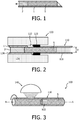
- Figure 4 shows such an extension of the system 100 comprising a container 130 formed by a planar substrate 131 with a bearing 132 comprising a cylindrical bore in which the sample holder 110 can be inserted for investigation with the microscope 140.
- the substrate 131 is preferably made of a transparent material, particularly a material having a similar index of refraction as the tubular member 111 of the sample holder 110.
- the gap between the sample holder 110 and the bore of the bearing 132 may be filled with an index-matching fluid to allow for improved optical quality.
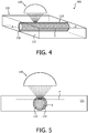
- Figure 5 schematically shows a section through the container 130 with the sample holder 110 in a direction perpendicular to the axis A of extension of the sample holder. It illustrates the confocal scanning indicating possible focal planes P in the cylindrical biopsy S. Multiple focal planes can be scanned to obtain a quasi-3D image of the biopsy. From the image an area of interest can be obtained, indicating for instance a high concentration of tumor cells. This area of interest can be easily translated into a volume of interest, or zone of interest that can be removed from the cylindrical biopsy inside the container readily. The advantage of this approach is that no material is lost from the volume of interest in contrast to the conventional selection from individual slices on microscopy slides.
- the tubular member 111 of the sample holder 110 typically has in interior diameter D of about 0.2 mm to about 2 mm. This may imply longer diffusion times as compared to tissue slices on a slide. However, it is not required to stain a sample S in the tubular member 111 to the full depth but rather to the depth of focus that is used in the image acquisition.
- the arrangement with a container as depicted in Figures 4 and 5 can also be used for the fixation and staining of the specimen, where the index matching liquid is replaced by a fixation or staining solution.
- Figure 6 shows in this respect a section through a medial plane of a preferred embodiment of the container 130.
- the container comprises a bearing 132 with a bore in which a sample holder 110 with a specimen S is placed.
- it comprises a fluidic system 133 that accommodates the sample holder 110 (or at least a part thereof).
- the fluidic system 133 comprises a fluid inlet/outlet 135 and a pumping device 134 for generating a convection of reagent fluid around the sample holder 110.
- the transition between the bearing 132 and the fluidic system 133 is preferably sealed (not shown).
- Figure 7 illustrates an alternative embodiment of a system 200 with a sample holder 210 and a container 230.
- the container 230 comprises a fluidic system 233 with an inlet/outlet 235, a pumping device 234, and a cavity 232 into which the tubular member 211 of the sample holder 210 is permanently integrated.
- the tubular member 211 may for example comprise a cylindrical wall that is integral with the material of the container and that comprises a plurality of apertures or fluidic channels through which reagents can reach a sample S in the interior of the sample holder 210.
- the permanent wall 211 hence takes the role of the membrane in the above embodiments.
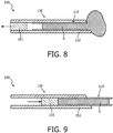
- Figure 9 shows the subsequent ejection of the sample holder 110 together with the sample S from the extraction device 150.
- This ejection can for example be achieved with the help of the piston 151.
- the sample holder 110 can thereafter be used as desired, for example be transferred to a container 130 for optical examination.
- the solutions can be actively pumped axially or radially across the specimen via the appropriate arrangement of fluidic channels.
- the channel dimensions can be kept small to reduce reagent consumption and achieve strong convective flow to enhance diffusion.
- the container 130 can be designed as microfluidic cartridge with the necessary interface for liquid supply (e.g. tubes and reservoirs) and actuation (e.g. pneumatic actuation or syringes).
- the biopsy is transferred from e.g. a needle core into a dedicated tube to preserve the shape and avoid breakage.
- the tube is preferably made of an optically clear material that is permeable for chemical reagents to allow for fixation and staining of the tissue.
- the staining reactions are carried out with the fully intact biopsy.
- the biopsy can be investigated by optical microscopy in brightfield or fluorescence or a digital scanning microscope. This can either be done by for example rotating the cylindrical sample with line illumination to investigate a large area, or alternatively the tube can be inserted into a substantially flat substrate with index-matching fluid for optical investigation with conventional means.
- the depth of focus can be varied to obtain information from layers beneath the surface of the biopsy and/or to obtain 3D information.
- the approach can inter alia be applied in histopathology, biopsy taking, tissue processing, molecular pathology, in particular for patient stratification in oncology based on identification of molecular changes in cancer cells.
Landscapes
- Health & Medical Sciences (AREA)
- Chemical & Material Sciences (AREA)
- Analytical Chemistry (AREA)
- General Health & Medical Sciences (AREA)
- Life Sciences & Earth Sciences (AREA)
- Biochemistry (AREA)
- Pathology (AREA)
- Immunology (AREA)
- General Physics & Mathematics (AREA)
- Physics & Mathematics (AREA)
- Hematology (AREA)
- Chemical Kinetics & Catalysis (AREA)
- Clinical Laboratory Science (AREA)
- Engineering & Computer Science (AREA)
- Biomedical Technology (AREA)
- Molecular Biology (AREA)
- Dispersion Chemistry (AREA)
- Sampling And Sample Adjustment (AREA)
- Investigating Or Analysing Biological Materials (AREA)
- Optical Measuring Cells (AREA)
Claims (15)
- System (100, 200) zum Verarbeiten einer biologischen Probe (S), wobei die biologische Probe eine Biopsie ist, wobei das System einen Probenhalter (110, 210) und mindestens eine Zusatzkomponente (120, 130, 150) umfasst, wobei der Probenhalter ein röhrenförmiges Element (111, 211) umfasst, wobei das röhrenförmige Element (111, 211) eine Wand umfasst, die mindestens teilweise aus einem transparenten Material besteht, und wobei jede der mindestens einen Zusatzkomponente (120, 130, 150) ein Lager (123, 132, 232, 152) aufweist, das mit mindestens einem Teil des röhrenförmigen Elements (111, 211) des Probenhalters (110, 210) gekoppelt werden kann, dadurch gekennzeichnet, dass das röhrenförmige Element (111, 211) einen Bereich umfasst, in dem die Wand für Reagenzien durchlässig ist.
- System (100, 200) nach Anspruch 1, dadurch gekennzeichnet, dass das röhrenförmige Element (111, 211) einen Innendurchmesser (D) zwischen 0,2 mm und 2 mm aufweist.
- System (100, 200) nach Anspruch 1 oder 2, dadurch gekennzeichnet, dass das röhrenförmige Element (111) zumindest teilweise aus einer Membran, insbesondere einer porösen Polymermembran, besteht und/oder dass das röhrenförmige Element (211) fluidische Kanäle umfasst, durch die eine Probe (S) im röhrenförmigen Element (211) zugänglich ist.
- System (100, 200) nach einem der Ansprüche 1 bis 3, dadurch gekennzeichnet, dass- mindestens eine der mindestens einen Zusatzkomponente eine Transfervorrichtung (120) zum Transferieren einer Probe (S) von einer Extraktionsvorrichtung (1), die eine Kernnadel ist, in den Probenhalter (110) ist, wobei die Transfervorrichtung einen Transferkanal (122) mit einem ersten Ende (123), mit dem der Probenhalter (110) verbunden werden kann, und mit einem zweiten Ende (124), mit dem die Extraktionsvorrichtung (1) verbunden sein kann, umfasst; oder- das System eine Extraktionsvorrichtung (1) zum Extrahieren einer Probe (S) von einem Subjekt beinhaltet, und mindestens eine der mindestens einen Zusatzkomponente eine Transfervorrichtung (120) zum Transferieren einer Probe (S) von einer Extraktionsvorrichtung (1), die eine Kernnadel ist, in den Probenhalter (110) ist, wobei die Transfervorrichtung einen Transferkanal (122) mit einem ersten Ende (123) umfasst, mit dem der Probenhalter (110) verbunden werden kann, und mit einem zweiten Ende (124), mit dem die Extraktionsvorrichtung (1) verbunden werden kann; und/oder- mindestens eine der mindestens einen Zusatzkomponenten eine Extraktionsvorrichtung (150) zum Extrahieren der Probe (S) aus einem Subjekt ist, wobei die Extraktionsvorrichtung ein Lager (152) zur Aufnahme des Probenhalters (110) aufweist, so dass eine extrahierte Probe vom Probenhalter aufgenommen wird; und/oder- mindestens eine der mindestens einen Zusatzkomponente ein Behälter (130) mit einem Lager (132, 232) zur austauschbaren oder dauerhaften Aufnahme des Probenhalters (110) ist.
- System (100, 200) nach Anspruch 4, dadurch gekennzeichnet, dass das Lager (123, 132, 232, 152) eine geschlossene Verbindung der Transfervorrichtung (120) mit dem Probenhalter (110, 210) ermöglicht.
- System (100, 200) nach einem der Ansprüche 1 bis 5, dadurch gekennzeichnet, dass es eine optische Einrichtung (140) zum Erzeugen von Bildern einer Probe (S) in dem Probenhalter (110) umfasst.
- System (100, 200) nach einem der Ansprüche 1 bis 6, dadurch gekennzeichnet, dass mindestens eine der mindestens einen Zusatzkomponenten ein Behälter (130) mit einem Lager (132, 232) zur austauschbaren oder dauerhaften Aufnahme des Probenhalters (110) ist und dass der Probenhalter (110) im Behälter (130) drehbar gelagert werden kann oder ist und/oder dass der Probenhalter (110) in axialer Richtung (A) innerhalb des Behälters (130) beweglich ist.
- System (100, 200) nach einem der Ansprüche 1 bis 7, dadurch gekennzeichnet, dass mindestens eine der mindestens einen der Zusatzkomponente ein Behälter (130) mit einem Lager (132, 232) zur austauschbaren oder dauerhaften Aufnahme des Probenhalters (110) ist und dass das Lager (132, 232) des Behälters (130, 230) einen Hohlraum definiert, in dem zumindest teilweise mit einem Fluid gefüllt und der Probenhalter (110, 210) zum Eintauchen in das Fluid aufgenommen werden kann.
- System (100) nach einem der Ansprüche 1 bis 8, dadurch gekennzeichnet, dass mindestens eine der mindestens einen Zusatzkomponente ein Behälter (130) mit einem Lager (132, 232) zur austauschbaren oder dauerhaften Aufnahme des Probenhalters (110) ist und dass der Behälter (130) ein Substrat (131) mit einem Lager (132) umfasst, das eine Bohrung in Form des röhrenförmige Elements (111) des Probenhalters (110) definiert.
- System (100, 200) nach einem der Ansprüche 1 bis 9, dadurch gekennzeichnet, dass mindestens eine der mindestens einen Zusatzkomponente ein Behälter (130) mit einem Lager (132, 232) zur austauschbaren oder dauerhaften Aufnahme des Probenhalters (110) ist und dass der Behälter (130, 230) ein fluidisches System (133, 134, 135, 233, 234, 235) zum Steuern des Fluidstroms um das röhrenförmige Element (111, 211) des Probenhalters (110, 210) herum umfasst.
- System (100, 200) nach einem der Ansprüche 1 bis 10, dadurch gekennzeichnet, dass der für Reagenzien durchlässige Bereich der Wand des röhrenförmigen Elements (111, 211) eine Vielzahl von Öffnungen oder Poren umfasst.
- System (100, 200) nach einem der Ansprüche 1 bis 11, dadurch gekennzeichnet, dass die Wände des röhrenförmigen Elements (111, 211) aus einem optisch transparenten Membranmaterial bestehen.
- Verfahren zum Verarbeiten einer biologischen Probe (S), wobei die biologische Probe eine Biopsie ist, wobei das Verfahren die folgenden Schritte umfasst:- Transferieren der Probe in einen Probenhalter (110, 210) mit einem röhrenförmigen Element (111, 211) mit einer Wand, die zumindest lokal transparent ist und einen Bereich umfasst, in dem die Wand für Reagenzien durchlässig ist, wobei das röhrenförmige Element (111, 211) zumindest teilweise aus einem transparenten Material besteht;- Aussetzen des Probenhalters (110, 210) gegenüber mindestens einem Reagenz, das in einer Lösung gelöst ist, so dass das Reagenz die Probe (S) im röhrenförmigen Element (111, 211) erreichen kann.
- Verfahren nach Anspruch 13, dadurch gekennzeichnet, dass es weiter mindestens einen der folgenden Schritte umfasst:- optische Untersuchung der Probe (S) im Probenhalter (110);- Extrahieren eines Bereichs von Interesse (ROI) der Probe (S) aus dem Probenhalter (110).
- Verfahren nach Anspruch 13 oder 14, dadurch gekennzeichnet, dass die Reagenzien ein Fixierungsreagenz, Permeabilisierungsreagenz, Waschreagenz, Antiquenchreagenz und/oder ein Färbereagenz umfassen.
Applications Claiming Priority (2)
| Application Number | Priority Date | Filing Date | Title |
|---|---|---|---|
| EP14175012 | 2014-06-30 | ||
| PCT/EP2015/064677 WO2016001126A1 (en) | 2014-06-30 | 2015-06-29 | Sample holder for biological samples |
Publications (2)
| Publication Number | Publication Date |
|---|---|
| EP3160644A1 EP3160644A1 (de) | 2017-05-03 |
| EP3160644B1 true EP3160644B1 (de) | 2019-05-08 |
Family
ID=51014221
Family Applications (1)
| Application Number | Title | Priority Date | Filing Date |
|---|---|---|---|
| EP15734108.2A Active EP3160644B1 (de) | 2014-06-30 | 2015-06-29 | Probenhalter für biologische proben |
Country Status (8)
| Country | Link |
|---|---|
| US (1) | US11513038B2 (de) |
| EP (1) | EP3160644B1 (de) |
| JP (1) | JP6571694B2 (de) |
| CN (1) | CN106536054B (de) |
| MX (1) | MX2016016469A (de) |
| RU (1) | RU2686937C2 (de) |
| TR (1) | TR201910628T4 (de) |
| WO (1) | WO2016001126A1 (de) |
Families Citing this family (5)
| Publication number | Priority date | Publication date | Assignee | Title |
|---|---|---|---|---|
| EP3435759B1 (de) * | 2016-03-31 | 2021-04-21 | Snpshot Trustee Limited | Vorrichtung zur probenahme |
| EP3372981A1 (de) * | 2017-03-10 | 2018-09-12 | Koninklijke Philips N.V. | Vorrichtung zum verarbeiten von 3d-biopsiegewebe |
| EP3611695A1 (de) * | 2018-08-15 | 2020-02-19 | Koninklijke Philips N.V. | Erzeugung von anmerkungsdaten von gewebebildern |
| DE102019121541B4 (de) * | 2019-08-09 | 2021-07-01 | Schott Ag | Aufnahme zum sterilen Halten eines Sensors für einen Bioreaktor sowie Bioreaktor mit Aufnahme zum sterilen Halten eines Sensors und Verfahren zur Vermehrung oder Kultivierung biologischen Materials |
| CN112221544B (zh) * | 2020-09-27 | 2022-06-17 | 北京理工大学重庆创新中心 | 一种集采样与检测一体化的微流控芯片 |
Family Cites Families (20)
| Publication number | Priority date | Publication date | Assignee | Title |
|---|---|---|---|---|
| US3498909A (en) | 1966-12-29 | 1970-03-03 | Mc Donnell Douglas Corp | Desalination apparatus and process |
| US3634651A (en) * | 1970-12-04 | 1972-01-11 | Becton Dickinson Co | Serological incubator |
| US4966707A (en) | 1986-05-13 | 1990-10-30 | Celanese Corporation | Liquid/liquid extractions with microporous membranes |
| GB9409360D0 (en) * | 1994-05-11 | 1994-06-29 | Peas And Beans Limited | Improvements in or relating to gas collection |
| GB9426251D0 (en) | 1994-12-24 | 1995-02-22 | Fsm Technologies Ltd | Device |
| JP3049537B2 (ja) * | 1995-02-03 | 2000-06-05 | 悌二 竹崎 | 生検試料の定着支持方法とその定着支持剤及び包埋カセット |
| EP0853238B1 (de) * | 1997-01-13 | 2002-09-18 | Daniel Dr. Studer | Probenhalter für wasserhaltige Proben sowie Verfahren zu deren Verwendung |
| US7799521B2 (en) * | 1998-06-24 | 2010-09-21 | Chen & Chen, Llc | Thermal cycling |
| US6411434B1 (en) | 1999-02-17 | 2002-06-25 | Lucid, Inc. | Cassette for facilitating optical sectioning of a retained tissue specimen |
| IT1305303B1 (it) | 1999-03-10 | 2001-05-04 | Farmigea Spa | Uso dell'olio essenziale di niaouli come promotore per la permeazionetransdermica. |
| DE10054621A1 (de) * | 1999-11-19 | 2001-05-23 | Leica Mikrosysteme Ag Wien | Biopsienadel |
| JP2002214093A (ja) * | 2001-01-22 | 2002-07-31 | Murazumi Kogyo Kk | 医療検査用カセット |
| JP4058709B2 (ja) * | 2001-04-03 | 2008-03-12 | 悌二 竹崎 | 病理組織試料用カセットとそれを用いた包埋ブロックの成形方法 |
| JP4280690B2 (ja) * | 2004-08-06 | 2009-06-17 | 社団法人 家畜改良事業団 | サンプル容器およびサンプル容器用圧着装置 |
| FR2878426B1 (fr) | 2004-11-30 | 2007-03-02 | Eric Peltier | Flacon de preparation d'une suspension cytologique |
| JP4792586B2 (ja) * | 2005-12-27 | 2011-10-12 | 国立大学法人京都大学 | 生物組織固定・包埋・薄切用カセット及びその操作方法 |
| RU2298798C1 (ru) * | 2006-01-17 | 2007-05-10 | Общество с ограниченной ответственностью "Биочип-Аналитика" (ООО "Биочип-Аналитика") | Способ контроля биологической пробы в реакции латекс-агглютинации и аналитическая система для его осуществления |
| US20070163942A1 (en) | 2006-01-19 | 2007-07-19 | Toray Industries, Inc. | Hollow fiber membrane module |
| CA2741187A1 (en) * | 2008-10-20 | 2010-04-29 | Spine View, Inc. | Retractor cannula system for accessing and visualizing spine and related methods |
| US7869049B2 (en) | 2009-05-06 | 2011-01-11 | Ut-Battelle, Llc | Determining biological tissue optical properties via integrating sphere spatial measurements |
-
2015
- 2015-06-29 JP JP2016575376A patent/JP6571694B2/ja active Active
- 2015-06-29 EP EP15734108.2A patent/EP3160644B1/de active Active
- 2015-06-29 TR TR2019/10628T patent/TR201910628T4/tr unknown
- 2015-06-29 WO PCT/EP2015/064677 patent/WO2016001126A1/en active Application Filing
- 2015-06-29 CN CN201580036102.1A patent/CN106536054B/zh active Active
- 2015-06-29 MX MX2016016469A patent/MX2016016469A/es unknown
- 2015-06-29 US US15/322,495 patent/US11513038B2/en active Active
- 2015-06-29 RU RU2017102491A patent/RU2686937C2/ru active
Non-Patent Citations (1)
| Title |
|---|
| None * |
Also Published As
| Publication number | Publication date |
|---|---|
| CN106536054B (zh) | 2020-04-28 |
| TR201910628T4 (tr) | 2019-08-21 |
| US20170138822A1 (en) | 2017-05-18 |
| WO2016001126A1 (en) | 2016-01-07 |
| EP3160644A1 (de) | 2017-05-03 |
| RU2686937C2 (ru) | 2019-05-06 |
| CN106536054A (zh) | 2017-03-22 |
| JP6571694B2 (ja) | 2019-09-04 |
| RU2017102491A3 (de) | 2019-01-28 |
| RU2017102491A (ru) | 2018-07-30 |
| US11513038B2 (en) | 2022-11-29 |
| JP2017524923A (ja) | 2017-08-31 |
| MX2016016469A (es) | 2017-04-10 |
Similar Documents
| Publication | Publication Date | Title |
|---|---|---|
| EP3160644B1 (de) | Probenhalter für biologische proben | |
| US11229910B2 (en) | Microfluidic devices and systems for cell culture and/or assay | |
| US5301685A (en) | Method and apparatus for obtaining a cytology monolayer | |
| JP2020042050A (ja) | 統合された移送モジュールを有する試験カートリッジ | |
| JP4074058B2 (ja) | 流体試料と粒子物質を混合および流体試料から粒子物質を分離をする方法、およびその装置 | |
| JP5254000B2 (ja) | 液体中に含まれる生物学的粒子を垂直濾過することによって分離する方法及び装置 | |
| US20090311717A1 (en) | Microfluidic chip design comprising capillaries | |
| ES2949108T3 (es) | Aparato de muestreo para la separación de sangre completa | |
| US6750039B1 (en) | Filtration apparatus and method for the separation of microscopic entities from a fluid | |
| EP2855020A2 (de) | Diagnostische mikrosiebvorrichtung bei der isolierung und analyse von einzelzellen | |
| US20140329300A1 (en) | Device for analyzing a sample and method of using the same | |
| JP2005300528A (ja) | 検体の検査方法に使用する分析要素。 | |
| WO2020168085A2 (en) | Medical apparatus and method for collection and preparation of biological samples | |
| JPH10508699A (ja) | 光学的解析用物体の調製方法及び装置 | |
| US20170205320A1 (en) | Method and apparatus for cell block preparation of cytology specimens | |
| WO2017087703A1 (en) | Sample processing and smearing apparatus and methods | |
| JP2006300667A (ja) | 包埋支持剤の固定固化器具及び生物試料の保持方法並びにテッシュアレイヤーゲル | |
| US6106483A (en) | Apparatus for obtaining a cytology monolayer | |
| EP1455187A1 (de) | Vorrichtung zum Filtern und Überführen von Teilchen | |
| US11555765B2 (en) | Tissue chamber | |
| CN115734820A (zh) | 用于小液体体积的容器 |
Legal Events
| Date | Code | Title | Description |
|---|---|---|---|
| STAA | Information on the status of an ep patent application or granted ep patent |
Free format text: STATUS: THE INTERNATIONAL PUBLICATION HAS BEEN MADE |
|
| PUAI | Public reference made under article 153(3) epc to a published international application that has entered the european phase |
Free format text: ORIGINAL CODE: 0009012 |
|
| STAA | Information on the status of an ep patent application or granted ep patent |
Free format text: STATUS: REQUEST FOR EXAMINATION WAS MADE |
|
| 17P | Request for examination filed |
Effective date: 20170130 |
|
| AK | Designated contracting states |
Kind code of ref document: A1 Designated state(s): AL AT BE BG CH CY CZ DE DK EE ES FI FR GB GR HR HU IE IS IT LI LT LU LV MC MK MT NL NO PL PT RO RS SE SI SK SM TR |
|
| AX | Request for extension of the european patent |
Extension state: BA ME |
|
| DAV | Request for validation of the european patent (deleted) | ||
| DAX | Request for extension of the european patent (deleted) | ||
| STAA | Information on the status of an ep patent application or granted ep patent |
Free format text: STATUS: EXAMINATION IS IN PROGRESS |
|
| 17Q | First examination report despatched |
Effective date: 20171213 |
|
| GRAP | Despatch of communication of intention to grant a patent |
Free format text: ORIGINAL CODE: EPIDOSNIGR1 |
|
| STAA | Information on the status of an ep patent application or granted ep patent |
Free format text: STATUS: GRANT OF PATENT IS INTENDED |
|
| RIC1 | Information provided on ipc code assigned before grant |
Ipc: B01L 3/00 20060101AFI20180622BHEP Ipc: B01D 63/00 20060101ALI20180622BHEP Ipc: G01N 1/08 20060101ALI20180622BHEP Ipc: A61B 10/00 20060101ALI20180622BHEP Ipc: A61B 10/02 20060101ALI20180622BHEP Ipc: G01N 1/31 20060101ALI20180622BHEP |
|
| INTG | Intention to grant announced |
Effective date: 20180720 |
|
| GRAJ | Information related to disapproval of communication of intention to grant by the applicant or resumption of examination proceedings by the epo deleted |
Free format text: ORIGINAL CODE: EPIDOSDIGR1 |
|
| STAA | Information on the status of an ep patent application or granted ep patent |
Free format text: STATUS: EXAMINATION IS IN PROGRESS |
|
| GRAP | Despatch of communication of intention to grant a patent |
Free format text: ORIGINAL CODE: EPIDOSNIGR1 |
|
| STAA | Information on the status of an ep patent application or granted ep patent |
Free format text: STATUS: GRANT OF PATENT IS INTENDED |
|
| INTC | Intention to grant announced (deleted) | ||
| INTG | Intention to grant announced |
Effective date: 20181212 |
|
| GRAS | Grant fee paid |
Free format text: ORIGINAL CODE: EPIDOSNIGR3 |
|
| GRAA | (expected) grant |
Free format text: ORIGINAL CODE: 0009210 |
|
| STAA | Information on the status of an ep patent application or granted ep patent |
Free format text: STATUS: THE PATENT HAS BEEN GRANTED |
|
| AK | Designated contracting states |
Kind code of ref document: B1 Designated state(s): AL AT BE BG CH CY CZ DE DK EE ES FI FR GB GR HR HU IE IS IT LI LT LU LV MC MK MT NL NO PL PT RO RS SE SI SK SM TR |
|
| REG | Reference to a national code |
Ref country code: GB Ref legal event code: FG4D |
|
| REG | Reference to a national code |
Ref country code: CH Ref legal event code: EP Ref country code: AT Ref legal event code: REF Ref document number: 1129338 Country of ref document: AT Kind code of ref document: T Effective date: 20190515 |
|
| REG | Reference to a national code |
Ref country code: DE Ref legal event code: R096 Ref document number: 602015029852 Country of ref document: DE Ref country code: IE Ref legal event code: FG4D |
|
| REG | Reference to a national code |
Ref country code: NL Ref legal event code: MP Effective date: 20190508 |
|
| REG | Reference to a national code |
Ref country code: LT Ref legal event code: MG4D |
|
| PG25 | Lapsed in a contracting state [announced via postgrant information from national office to epo] |
Ref country code: AL Free format text: LAPSE BECAUSE OF FAILURE TO SUBMIT A TRANSLATION OF THE DESCRIPTION OR TO PAY THE FEE WITHIN THE PRESCRIBED TIME-LIMIT Effective date: 20190508 Ref country code: PT Free format text: LAPSE BECAUSE OF FAILURE TO SUBMIT A TRANSLATION OF THE DESCRIPTION OR TO PAY THE FEE WITHIN THE PRESCRIBED TIME-LIMIT Effective date: 20190908 Ref country code: NO Free format text: LAPSE BECAUSE OF FAILURE TO SUBMIT A TRANSLATION OF THE DESCRIPTION OR TO PAY THE FEE WITHIN THE PRESCRIBED TIME-LIMIT Effective date: 20190808 Ref country code: FI Free format text: LAPSE BECAUSE OF FAILURE TO SUBMIT A TRANSLATION OF THE DESCRIPTION OR TO PAY THE FEE WITHIN THE PRESCRIBED TIME-LIMIT Effective date: 20190508 Ref country code: NL Free format text: LAPSE BECAUSE OF FAILURE TO SUBMIT A TRANSLATION OF THE DESCRIPTION OR TO PAY THE FEE WITHIN THE PRESCRIBED TIME-LIMIT Effective date: 20190508 Ref country code: SE Free format text: LAPSE BECAUSE OF FAILURE TO SUBMIT A TRANSLATION OF THE DESCRIPTION OR TO PAY THE FEE WITHIN THE PRESCRIBED TIME-LIMIT Effective date: 20190508 Ref country code: HR Free format text: LAPSE BECAUSE OF FAILURE TO SUBMIT A TRANSLATION OF THE DESCRIPTION OR TO PAY THE FEE WITHIN THE PRESCRIBED TIME-LIMIT Effective date: 20190508 Ref country code: ES Free format text: LAPSE BECAUSE OF FAILURE TO SUBMIT A TRANSLATION OF THE DESCRIPTION OR TO PAY THE FEE WITHIN THE PRESCRIBED TIME-LIMIT Effective date: 20190508 Ref country code: LT Free format text: LAPSE BECAUSE OF FAILURE TO SUBMIT A TRANSLATION OF THE DESCRIPTION OR TO PAY THE FEE WITHIN THE PRESCRIBED TIME-LIMIT Effective date: 20190508 |
|
| PG25 | Lapsed in a contracting state [announced via postgrant information from national office to epo] |
Ref country code: RS Free format text: LAPSE BECAUSE OF FAILURE TO SUBMIT A TRANSLATION OF THE DESCRIPTION OR TO PAY THE FEE WITHIN THE PRESCRIBED TIME-LIMIT Effective date: 20190508 Ref country code: GR Free format text: LAPSE BECAUSE OF FAILURE TO SUBMIT A TRANSLATION OF THE DESCRIPTION OR TO PAY THE FEE WITHIN THE PRESCRIBED TIME-LIMIT Effective date: 20190809 Ref country code: BG Free format text: LAPSE BECAUSE OF FAILURE TO SUBMIT A TRANSLATION OF THE DESCRIPTION OR TO PAY THE FEE WITHIN THE PRESCRIBED TIME-LIMIT Effective date: 20190808 Ref country code: LV Free format text: LAPSE BECAUSE OF FAILURE TO SUBMIT A TRANSLATION OF THE DESCRIPTION OR TO PAY THE FEE WITHIN THE PRESCRIBED TIME-LIMIT Effective date: 20190508 |
|
| REG | Reference to a national code |
Ref country code: AT Ref legal event code: MK05 Ref document number: 1129338 Country of ref document: AT Kind code of ref document: T Effective date: 20190508 |
|
| PG25 | Lapsed in a contracting state [announced via postgrant information from national office to epo] |
Ref country code: CZ Free format text: LAPSE BECAUSE OF FAILURE TO SUBMIT A TRANSLATION OF THE DESCRIPTION OR TO PAY THE FEE WITHIN THE PRESCRIBED TIME-LIMIT Effective date: 20190508 Ref country code: SK Free format text: LAPSE BECAUSE OF FAILURE TO SUBMIT A TRANSLATION OF THE DESCRIPTION OR TO PAY THE FEE WITHIN THE PRESCRIBED TIME-LIMIT Effective date: 20190508 Ref country code: RO Free format text: LAPSE BECAUSE OF FAILURE TO SUBMIT A TRANSLATION OF THE DESCRIPTION OR TO PAY THE FEE WITHIN THE PRESCRIBED TIME-LIMIT Effective date: 20190508 Ref country code: AT Free format text: LAPSE BECAUSE OF FAILURE TO SUBMIT A TRANSLATION OF THE DESCRIPTION OR TO PAY THE FEE WITHIN THE PRESCRIBED TIME-LIMIT Effective date: 20190508 Ref country code: DK Free format text: LAPSE BECAUSE OF FAILURE TO SUBMIT A TRANSLATION OF THE DESCRIPTION OR TO PAY THE FEE WITHIN THE PRESCRIBED TIME-LIMIT Effective date: 20190508 Ref country code: EE Free format text: LAPSE BECAUSE OF FAILURE TO SUBMIT A TRANSLATION OF THE DESCRIPTION OR TO PAY THE FEE WITHIN THE PRESCRIBED TIME-LIMIT Effective date: 20190508 |
|
| REG | Reference to a national code |
Ref country code: CH Ref legal event code: PL |
|
| REG | Reference to a national code |
Ref country code: DE Ref legal event code: R097 Ref document number: 602015029852 Country of ref document: DE |
|
| PG25 | Lapsed in a contracting state [announced via postgrant information from national office to epo] |
Ref country code: IT Free format text: LAPSE BECAUSE OF FAILURE TO SUBMIT A TRANSLATION OF THE DESCRIPTION OR TO PAY THE FEE WITHIN THE PRESCRIBED TIME-LIMIT Effective date: 20190508 Ref country code: MC Free format text: LAPSE BECAUSE OF FAILURE TO SUBMIT A TRANSLATION OF THE DESCRIPTION OR TO PAY THE FEE WITHIN THE PRESCRIBED TIME-LIMIT Effective date: 20190508 Ref country code: SM Free format text: LAPSE BECAUSE OF FAILURE TO SUBMIT A TRANSLATION OF THE DESCRIPTION OR TO PAY THE FEE WITHIN THE PRESCRIBED TIME-LIMIT Effective date: 20190508 |
|
| PLBE | No opposition filed within time limit |
Free format text: ORIGINAL CODE: 0009261 |
|
| STAA | Information on the status of an ep patent application or granted ep patent |
Free format text: STATUS: NO OPPOSITION FILED WITHIN TIME LIMIT |
|
| RAP2 | Party data changed (patent owner data changed or rights of a patent transferred) |
Owner name: KONINKLIJKE PHILIPS N.V. |
|
| REG | Reference to a national code |
Ref country code: BE Ref legal event code: MM Effective date: 20190630 |
|
| 26N | No opposition filed |
Effective date: 20200211 |
|
| PG25 | Lapsed in a contracting state [announced via postgrant information from national office to epo] |
Ref country code: IE Free format text: LAPSE BECAUSE OF NON-PAYMENT OF DUE FEES Effective date: 20190629 Ref country code: PL Free format text: LAPSE BECAUSE OF FAILURE TO SUBMIT A TRANSLATION OF THE DESCRIPTION OR TO PAY THE FEE WITHIN THE PRESCRIBED TIME-LIMIT Effective date: 20190508 |
|
| PG25 | Lapsed in a contracting state [announced via postgrant information from national office to epo] |
Ref country code: LU Free format text: LAPSE BECAUSE OF NON-PAYMENT OF DUE FEES Effective date: 20190629 Ref country code: SI Free format text: LAPSE BECAUSE OF FAILURE TO SUBMIT A TRANSLATION OF THE DESCRIPTION OR TO PAY THE FEE WITHIN THE PRESCRIBED TIME-LIMIT Effective date: 20190508 Ref country code: BE Free format text: LAPSE BECAUSE OF NON-PAYMENT OF DUE FEES Effective date: 20190630 Ref country code: CH Free format text: LAPSE BECAUSE OF NON-PAYMENT OF DUE FEES Effective date: 20190630 Ref country code: LI Free format text: LAPSE BECAUSE OF NON-PAYMENT OF DUE FEES Effective date: 20190630 |
|
| PG25 | Lapsed in a contracting state [announced via postgrant information from national office to epo] |
Ref country code: CY Free format text: LAPSE BECAUSE OF FAILURE TO SUBMIT A TRANSLATION OF THE DESCRIPTION OR TO PAY THE FEE WITHIN THE PRESCRIBED TIME-LIMIT Effective date: 20190508 |
|
| PG25 | Lapsed in a contracting state [announced via postgrant information from national office to epo] |
Ref country code: IS Free format text: LAPSE BECAUSE OF FAILURE TO SUBMIT A TRANSLATION OF THE DESCRIPTION OR TO PAY THE FEE WITHIN THE PRESCRIBED TIME-LIMIT Effective date: 20190908 |
|
| PG25 | Lapsed in a contracting state [announced via postgrant information from national office to epo] |
Ref country code: MT Free format text: LAPSE BECAUSE OF FAILURE TO SUBMIT A TRANSLATION OF THE DESCRIPTION OR TO PAY THE FEE WITHIN THE PRESCRIBED TIME-LIMIT Effective date: 20190508 Ref country code: HU Free format text: LAPSE BECAUSE OF FAILURE TO SUBMIT A TRANSLATION OF THE DESCRIPTION OR TO PAY THE FEE WITHIN THE PRESCRIBED TIME-LIMIT; INVALID AB INITIO Effective date: 20150629 |
|
| PG25 | Lapsed in a contracting state [announced via postgrant information from national office to epo] |
Ref country code: MK Free format text: LAPSE BECAUSE OF FAILURE TO SUBMIT A TRANSLATION OF THE DESCRIPTION OR TO PAY THE FEE WITHIN THE PRESCRIBED TIME-LIMIT Effective date: 20190508 |
|
| PGFP | Annual fee paid to national office [announced via postgrant information from national office to epo] |
Ref country code: FR Payment date: 20230622 Year of fee payment: 9 Ref country code: DE Payment date: 20230627 Year of fee payment: 9 |
|
| PGFP | Annual fee paid to national office [announced via postgrant information from national office to epo] |
Ref country code: TR Payment date: 20230615 Year of fee payment: 9 |
|
| PGFP | Annual fee paid to national office [announced via postgrant information from national office to epo] |
Ref country code: GB Payment date: 20230620 Year of fee payment: 9 |
|
| REG | Reference to a national code |
Ref country code: DE Ref legal event code: R084 Ref document number: 602015029852 Country of ref document: DE |