EP3160550B1 - Nadellose injektionsvorrichtung mit doppelmembran - Google Patents
Nadellose injektionsvorrichtung mit doppelmembran Download PDFInfo
- Publication number
- EP3160550B1 EP3160550B1 EP15739529.4A EP15739529A EP3160550B1 EP 3160550 B1 EP3160550 B1 EP 3160550B1 EP 15739529 A EP15739529 A EP 15739529A EP 3160550 B1 EP3160550 B1 EP 3160550B1
- Authority
- EP
- European Patent Office
- Prior art keywords
- membrane
- skin
- injection device
- chamber
- needleless injection
- Prior art date
- Legal status (The legal status is an assumption and is not a legal conclusion. Google has not performed a legal analysis and makes no representation as to the accuracy of the status listed.)
- Active
Links
Images

Classifications
-
- A—HUMAN NECESSITIES
- A61—MEDICAL OR VETERINARY SCIENCE; HYGIENE
- A61M—DEVICES FOR INTRODUCING MEDIA INTO, OR ONTO, THE BODY; DEVICES FOR TRANSDUCING BODY MEDIA OR FOR TAKING MEDIA FROM THE BODY; DEVICES FOR PRODUCING OR ENDING SLEEP OR STUPOR
- A61M5/00—Devices for bringing media into the body in a subcutaneous, intra-vascular or intramuscular way; Accessories therefor, e.g. filling or cleaning devices, arm-rests
- A61M5/178—Syringes
- A61M5/30—Syringes for injection by jet action, without needle, e.g. for use with replaceable ampoules or carpules
-
- A—HUMAN NECESSITIES
- A61—MEDICAL OR VETERINARY SCIENCE; HYGIENE
- A61M—DEVICES FOR INTRODUCING MEDIA INTO, OR ONTO, THE BODY; DEVICES FOR TRANSDUCING BODY MEDIA OR FOR TAKING MEDIA FROM THE BODY; DEVICES FOR PRODUCING OR ENDING SLEEP OR STUPOR
- A61M5/00—Devices for bringing media into the body in a subcutaneous, intra-vascular or intramuscular way; Accessories therefor, e.g. filling or cleaning devices, arm-rests
- A61M5/178—Syringes
- A61M5/30—Syringes for injection by jet action, without needle, e.g. for use with replaceable ampoules or carpules
- A61M5/3015—Syringes for injection by jet action, without needle, e.g. for use with replaceable ampoules or carpules for injecting a dose of particles in form of powdered drug, e.g. mounted on a rupturable membrane and accelerated by a gaseous shock wave or supersonic gas flow
-
- A—HUMAN NECESSITIES
- A61—MEDICAL OR VETERINARY SCIENCE; HYGIENE
- A61M—DEVICES FOR INTRODUCING MEDIA INTO, OR ONTO, THE BODY; DEVICES FOR TRANSDUCING BODY MEDIA OR FOR TAKING MEDIA FROM THE BODY; DEVICES FOR PRODUCING OR ENDING SLEEP OR STUPOR
- A61M5/00—Devices for bringing media into the body in a subcutaneous, intra-vascular or intramuscular way; Accessories therefor, e.g. filling or cleaning devices, arm-rests
- A61M5/178—Syringes
- A61M5/31—Details
- A61M5/3129—Syringe barrels
-
- A—HUMAN NECESSITIES
- A61—MEDICAL OR VETERINARY SCIENCE; HYGIENE
- A61M—DEVICES FOR INTRODUCING MEDIA INTO, OR ONTO, THE BODY; DEVICES FOR TRANSDUCING BODY MEDIA OR FOR TAKING MEDIA FROM THE BODY; DEVICES FOR PRODUCING OR ENDING SLEEP OR STUPOR
- A61M2205/00—General characteristics of the apparatus
- A61M2205/82—Internal energy supply devices
- A61M2205/8206—Internal energy supply devices battery-operated
Definitions
- the invention relates to a needleless injection device or a device for needleless injection of a substance into a tissue or body, with which a substance, in particular an active ingredient, can preferably be injected using high pressure.
- a successful injection consists of introducing enough substance into the body through the tissue or body barrier, particularly those such as the skin.
- the basic principle of injecting a substance without a needle using high pressure has been known for some time (see e.g. US 3,308,818 ).
- needleless injection devices can consist of a pyrotechnic drive, which is used, for example, to actuate a piston and in this way produces the squeezing of an active ingredient from a cannula ( EP 1 557 190 A1 ).
- a further embodiment of a needleless injection device consists of a pyrotechnic approach, in which an explosion is generated in a chamber (also called a combustion chamber), with the released energy being used to transmit impulses to a membrane, whereby a membrane-adsorbed substance is detached from the membrane in the direction of the tissue is sufficiently accelerated.
- the present invention therefore refers to a generic embodiment according to WO 2004/071558 , but with the objective task of keeping the tissue or a body free of membrane parts and exhaust gases.
- the present invention therefore relates to a needleless injection device comprising a (combustion) chamber (11) containing a pyrotechnic material, wherein the chamber (11) has a fixed double membrane (13, 15) at an outlet opening, the skin-side membrane (15) being the Double membrane is provided with a substance application (25) to the skin side of the skin-side membrane (15), the combustion chamber-side membrane (13) and the skin-side membrane (15) being completely or partially bulged towards the chamber (11).
- the membrane (13) on the combustion chamber side opens into the combustion chamber (11) and its combustion chamber (24).
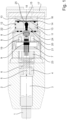
- FIG. 1 A basic and generic structure is in Figure 1 shown together with a legend, whereby the housing (22) and the parts (7) to (16) must be taken into account for the function of the injection device according to the invention.
- the parts (7) to (16) can be installed at any time in a differently shaped housing (22) and a detonator, in particular EED (10), can also be supplied with energy differently without changing the function of the parts or the device. Special embodiments are described in more detail.
- parts (7) to (9) can be integrated into one part, or part (7) can be omitted if part (8), for example, has an external thread and is screwed into the housing (22) - or, for example, using a snap ring in the housing (22) is held - or is an insert in the injection mold of the housing (22) (see also Figure 2 ).
- Parts (1), as well as parts (4) to (6) and (23) can also be omitted by using a conventional button for electrically contacting the detonator (EED) (10) with the battery (3).
- EED detonator
- pyrotechnic material is understood to mean any material that can be exploded with activation energy. These can be, for example, solid or gaseous substances such as azides, tetracenes, etc. or other pyrotechnic materials known to those skilled in the art. According to the invention, the explosion energy should ensure sufficient impulse transmission to the fixed one according to the invention Double membrane (13, 15) allow so that the applied substance (25) can be detached, accelerated and brought to high speeds.
- the pyrotechnic material is contained in a chamber (11), namely in the combustion chamber (24), the activation energy required to generate an explosion energy preferably taking place by means of a detonator (10), in particular by means of a mini detonator (EED) (10).
- a detonator (10) in particular by means of a mini detonator (EED) (10).
- the activation energy required to trigger an explosion in the chamber (11) can therefore be achieved by means of an activation unit, in particular not ultimately a detonator (10), igniter, ignition pin or igniter, namely via a triggering mechanism by means of friction, impact or a suitable power supply.
- a suitable activation unit is, for example, in Figure 1 shown.
- the battery (3) is pressed against a contact spring (6) and against a contact pin (5), thereby closing the circuit via the connections (9) and the EED (10) and as a result the ignition of the EEDs (10) brought about.
- Alternative triggering mechanisms are known to those skilled in the art (friction wire, impact wire, cracking frog striking shock-sensitive ignition mixture, etc.).
- said activation unit (1, 2, 3, 4, 5, 6, 7, 8, 9, 10) is aligned in the axial direction to the chamber (11) including the combustion chamber (24) and the fixed double membrane (13 , 15) opposite.
- a conventional igniter with or without additional charging can also be used instead of the detonator 10.
- impulse (transmission) is also synonymously understood to mean a force, pressure transmission or application, which is in any case sufficient for the substance(s) (25) applied to the skin-side membrane (15) of the double membrane (13, 15). ) to detach and accelerate to the desired high speeds, whereby they initially fly freely in the direction of the tissue or skin (18) or body in order to impact there, break through the tissue or body barrier and into the desired depth of the tissue, especially skin or body.
- skin means a tissue barrier of a human, mammal or animal.
- the skin performs numerous vital functions, especially the epidermis, which serves as a barrier organ. This barrier function is maintained, among other things, by skin lipids.
- epidermal lipids such as glycosphingolipids, ceramides, sterols and sterol esters, fatty acids, triglycerides, n-alkanes or various polar lipids are released in the keratinization process.
- the substances can enter the body locally and possibly flow into the bloodstream.
- the combustion chamber (24) in the chamber (11) can preferably be provided with a viscous, viscous mass, such as fat, oils and the like, in order to reduce the empty space in the combustion chamber (24) and thereby increase the pressure increase with a small charge of the detonator (EED) (10).
- EED detonator
- the chamber (11) preferably has O-rings for sealing (12). Furthermore, the chamber (11) can have a vent (20) including an associated cover (21).
- the fixed double membrane (13, 15) consists, preferably both the skin-side membrane (15) and the Combustion chamber-side membrane (13) made of metal or a material of appropriate hardness and ductility, such as steel, plastics, but particularly preferably titanium or titanium sheet. Titanium in particular has an advantageous high drawing limit with very good acceleration due to its lower specific density compared to steel and plastics, which means that a significantly higher speed of the bulging membrane is achieved at relatively low pressures in the combustion chamber.
- the membranes (13, 15) are flush or closed, that is, without holes, recesses, etc.
- the fixed double membrane Compared to a single membrane, the fixed double membrane combines greater operational reliability in the event of material defects or overloads (if a membrane tears, no exhaust gas escapes to the outside) with significantly better deformability, which allows the energy losses when deforming the double membrane to be minimized (i.e. instead of a 1 mm thick single membrane, two membranes, each 0.5 mm thick, are placed on top of each other to form a double membrane. Other thickness ratios are also possible, such as 0.6 mm towards the combustion chamber and 0.4 mm towards the skin.
- the term "fixed double membrane” (13, 15) means that both membranes - the double membrane - are attached / fixed with a support disk (16), in particular to the chamber (11), and are therefore not movable and are therefore locked and preferably the fixed one Double membrane or the combustion chamber-side membrane (13) opens directly into the chamber (11) or combustion chamber (24) (see Fig. 1 ). Furthermore, it is preferred that the inwardly directed membrane (13) on the combustion chamber side has a thickness of 0.1 mm to 0.6 mm, preferably 0.2 mm to 0.6 mm, particularly preferably 0.5 mm.
- the outwardly directed skin-side membrane (15) preferably also has a thickness of 0.1 mm to 0.6 mm, preferably 0.2 mm to 0.6 mm, particularly preferably 0.5 mm.
- the membranes (13, 15) can touch each other completely or partially.
- the combustion chamber-side membrane (13) has a distance from the skin-side membrane (15), preferably from 0.2 mm to 1.5 mm, particularly preferably 1 mm.
- the required distance can be set between the two membranes using a spacer (14). This measure efficiently prevents the skin-side membrane from bursting or bursting.
- the double membrane (13, 15) is completely or partially curved towards the chamber (11) and into its combustion chamber (24), over the entire surface or preferably in the central radial area around a circle center.
- a person skilled in the art can achieve such a concave curvature of the respective membranes from the perspective of the combustion chamber using known methods.
- the curvature of the double membrane (13, 15) according to the invention also allows an advantageous increased speed of 10 to 15%, including focusing and acceleration of the applied substances (25) towards the skin (18) - presumably through shock wave focusing.
- the two membranes (13, 15) have support disks (16).
- the support disks are preferably made of plastic, brass, etc., which are particularly suitable for absorbing energy.
- the support disk is energetically adapted, preferably with a taper towards the skin (18).
- the support disk (16) can be thinly coated on its inner contour with a soft plastic, for example with polyethylene, in order to advantageously significantly reduce the triggering noise of the device - for example, the bang-like noise that occurs when a metal membrane hits a metal support disk is avoided hits.
- the support disk also has the task of energetically decelerating the membranes after they have been pressurized and of long-term absorbing the high pressure that remains in the combustion chamber after they have been triggered and of supporting the membranes.
- the aforementioned embodiments advantageously allow at least the outer (skin-side) membrane of the double membrane to safely not burst or burst. Furthermore, it is advantageously achieved that the applied substances experience optimized impulse transmission or acceleration to very high speeds of up to 800m/sec.
- “applied substances (25)” means those that contain at least one substance and are fixed, for example with oils, among other things, to the outer (skin-side) membrane (15) or adhere by adhesion, the applied substances (25) for Skin side of the skin-side membrane (15) is applied.
- the applied substances can contain agents that allow the active ingredient to dry on the membrane in question.
- additional adhesion promoters or additives are suitable and should be added, such as oils or other preferably pharmaceutically suitable auxiliaries and additives.
- compositions includes all agents and substances that are suitable for expedient application to the membrane (e.g. powder, particles, etc.), including one or more active ingredients (e.g. drugs).
- active ingredients e.g. drugs
- the injection device can contain an attachment (17) which is ergonomically adapted to the tissue or skin (18) that is placed on it.
- the purpose of the attachment (17) is to safely keep the double membrane, which bulges out after the trigger, from the surface of the adjacent skin.
- holes or millings made in the attachment (17) can allow the air, which is simultaneously accelerated with the acceleration of the double membrane, to flow out parallel to the surface and prevent hydraulic coupling of the skin to the central hole above the double membrane, which would put undue gas pressure on the adjacent skin .
- substances in particular substances with any function and suitability, such as dyes or lubricants or materials with other special properties, for needleless introduction into surfaces or bodies of technical objects by means of the injection device according to the invention according to one of the above embodiments is possible.
- the invention therefore relates to an injection device according to one of the above embodiments for the use of a substance or an active ingredient, in particular medication, for needle-free application.
Landscapes
- Health & Medical Sciences (AREA)
- Engineering & Computer Science (AREA)
- Life Sciences & Earth Sciences (AREA)
- Vascular Medicine (AREA)
- Anesthesiology (AREA)
- Biomedical Technology (AREA)
- Heart & Thoracic Surgery (AREA)
- Hematology (AREA)
- Animal Behavior & Ethology (AREA)
- General Health & Medical Sciences (AREA)
- Public Health (AREA)
- Veterinary Medicine (AREA)
- Pharmacology & Pharmacy (AREA)
- Bioinformatics & Cheminformatics (AREA)
- Infusion, Injection, And Reservoir Apparatuses (AREA)
Description
- Die Erfindung betrifft eine nadellose Injektionsvorrichtung bzw. eine Vorrichtung zur nadellosen Injektion einer Substanz in ein Gewebe oder Körper, mit welcher vorzugsweise ein Stoff, insbesondere Wirkstoff mittels hohem Druck injiziert werden kann. Eine erfolgreiche Injektion besteht darin, dass genügend Substanz durch die Gewebe-, oder Körperbarriere, insbesondere solche wie die Haut, in den Körper eingebracht wird. Das Grundprinzip, einen Stoff nadellos mittels hohem Druck zu injizieren, ist seit geraumer Zeit bekannt (siehe z. B.
US 3,308,818 ). - Es sind verschiedene Typen von nadellosen Injektionsvorrichtungen im Stand der Technik beschrieben, wie z. B. nicht abschließend eine Zylinder-Kolben-Einheit umfassend ein vorgespanntes Federelement (
DE 10 2007 004 211 A1 ) oder mittels sogenannter Injektionspatronen (WO 98/31409 US 5,399,163 ). - Weiterhin können nadellose Injektionsvorrichtungen aus einem pyrotechnischen Antrieb bestehen, der beispielsweise zur Betätigung eines Kolbens genutzt wird und auf diese Weise das Auspressen eines Wirkstoffes aus einer Kanüle erzeugt (
EP 1 557 190 A1 ). - Eine weitere Ausführungsform einer nadellosen Injektionsvorrichtung besteht in einem pyrotechnischen Ansatz, wobei in einer Kammer (auch Brennkammer genannt) eine Explosion erzeugt wird, wobei die freigesetzte Energie zur Impulsübertragung auf eine Membran genutzt wird, wodurch eine membranständige adsorbierte Substanz unter Ablösung von der Membran in Richtung des Gewebes hinreichend beschleunigt wird.
- Eine solche gattungsmäßige Vorrichtung ist in
WO 2004/071558 A1 offenbart. Es gilt jedoch eine solche gattungsmäßige Ausführungsform zu verbessern. Insbesondere ist gemäß der Lehre vonWO 2004/071558 nachteilig, dass die vorgesehene Membran platzen kann und folglich nicht ausgeschlossen ist, dass Teile der Membran als auch die Abgase aus der Brennkammer / Verbrennungsraum das Gewebe unter Schädigung des Gewebes bzw. Körpers erreichen. - Von daher nimmt die vorliegende Erfindung Bezug auf eine gattungsmäßige Ausführungsform gemäß
WO 2004/071558 , jedoch mit der objektiven Aufgabenstellung, das Gewebe oder einen Körper von Membranteilen und Abgasen freizuhalten. - Daher betrifft die vorliegende Erfindung eine nadellose Injektionsvorrichtung umfassend eine (Brenn-)Kammer (11) enthaltend ein pyrotechnisches Material, wobei die Kammer (11) an einer Austrittsöffnung eine fixierte Doppelmembran (13, 15) aufweist, wobei die hautseitige Membran (15) der Doppelmembran mit einer Substanzauftragung (25) zur Hautseite der hautseitigen Membran (15) versehen ist, wobei die brennkammerseitige Membran (13) und die hautseitige Membran (15) zur Kammer (11) hin ganz oder teilweise ausgewölbt ist.
- Die brennkammerseitige Membran (13) mündet zur Brennkammer (11) und dessen Verbrennungsraum (24).
- Ein grundlegender und gattungsgemäßer Aufbau ist in
Figur 1 samt Legende gezeigt, wobei für die erfindungsgemäße Funktion der Injektionsvorrichtung das Gehäuse (22), sowie die Teile (7) bis (16) zu berücksichtigen sind. Die Teile (7) bis (16) können hierbei jederzeit in ein anders geformtes Gehäuse (22) eingebaut und ein Detonator, insbesondere EED (10), auch anders mit Energie versorgt werden, ohne die Funktion der Teile bzw. der Vorrichtung zu verändern. Besondere Ausführungsformen werden näher beschrieben. - Die Geometrie der einzelnen Teile in
Figur 1 können je nach Anforderung geändert oder teilweise integral zusammengefasst werden. Beispielsweise können Teile (7) bis (9) zu einem Teil integral zusammengefasst werden, oder Teil (7) kann entfallen, falls Teil (8) beispielsweise ein Außengewinde aufweist und in das Gehäuse (22) eingeschraubt wird - oder beispielsweise per Sprengring im Gehäuse (22) gehalten wird - oder ein Einlegeteil in der Spritzform des Gehäuses (22) ist (siehe ebenfallsFigur 2 ). Ebenfalls können die Teile (1), sowie die Teile (4) bis (6) und (23) durch die Verwendung eines herkömmlichen Tasters zur elektrischen Kontaktierung des Detonators (EED) (10) mit der Batterie (3) entfallen. - Im Rahmen dieser Erfindung wird unter "pyrotechnisches Material" ein jedes Material verstanden, welches mit einer Aktivierungsenergie zur Explosion gebracht werden kann. Dies können z.B. feste oder gasförmige Stoffe, wie Azide, Tetrazen, etc. oder anderen dem Fachmann bekannte pyrotechnische Materialien sein. Erfindungsgemäß soll die Explosionsenergie eine hinreichende Impulsübertragung auf die erfindungsgemäße fixierte Doppelmembran (13, 15) erlauben, so dass die aufgetragene Substanz (25) abgelöst, beschleunigt und auf hohe Geschwindigkeiten gebracht werden kann.
- Das pyrotechnische Material ist erfindungsgemäß in einer Kammer (11) enthalten und zwar im Verbrennungsraum (24), wobei die erforderliche Aktivierungsenergie zur Erzeugung einer Explosionsenergie vorzugsweise mittels eines Detonators (10), insbesondere mittels eines Minidetonators (EED) (10) erfolgt.
- Die erforderliche Aktivierungsenergie zur Explosionsauslösung in der Kammer (11) kann daher mittels einer Aktivierungseinheit erfolgen, insbesondere nicht abschließend einem Detonator (10), Anzünder, Zündstift oder Anzündstück und zwar über einen Auslösungsmechanismus mittels Reibung, Stoßen oder geeigneter Stromversorgung. Eine geeignete Aktivierungseinheit ist beispielsweise in
Figur 1 dargestellt. Mittels eines Auslösers oder Tasters (1) wird die Batterie (3) gegen eine Kontaktfeder (6) und gegen einen Kontaktstift (5) gedrückt, dadurch der Stromkreis über die Anschlüsse (9) und das EED (10) geschlossen und infolge die Zündung des EEDs (10) herbeigeführt. Alternative Auslösungsmechanismen sind dem Fachmann bekannt (Reibdraht, Schlagdraht, Knackfrosch auf stoßempfindliche Anzündmischung schlagend etc.). - In einer weiteren bevorzugten Ausführungsform ist die besagte Aktivierungseinheit (1, 2, 3, 4, 5, 6, 7, 8, 9, 10) in axialer Richtung zur Kammer (11) samt Verbrennungsraum (24) ausgerichtet und der fixierten Doppelmembran (13, 15) gegenüberliegend.
- Beispielsweise bei 20 bis 80 µm großen Zuckerpartikeln als aufgetragene Substanz (25) sind erfindungsgemäß Geschwindigkeiten von ca. 600 m/sec oder mehr zu erreichen. Größere Teilchen dringen wegen Ihres Impulses und des anwachsenden Verhältnisses von Dichte zum Radius deutlich einfacher in das Gewebe oder in den Körper ein, während kleinere Partikel hingegen eine deutlich höhere Geschwindigkeit als die genannten 600 m/sec benötigen.
- Falls kleinere Geschwindigkeiten der durch die Doppelmembran beschleunigten Teilchen bis ca. 400 m/sec ausreichen, kann beispielsweise anstelle des Detonators 10 auch ein herkömmlicher Anzünder mit oder ohne zusätzlicher Aufladung verwendet werden.
- Im Rahmen dieser Erfindung wird unter "Impuls(übertragung)" auch synonym eine Kraft-, Druckübertragung oder Beaufschlagung verstanden, welche jedenfalls ausreichend ist, die auf der hautseitigen Membran (15) der Doppelmembran (13, 15) aufgetragenen Substanz(en) (25) abzulösen und auf die gewünschten hohen Geschwindigkeiten zu beschleunigen, wodurch sie zunächst frei in Richtung des Gewebes bzw. Haut (18) oder Körper fliegen, um dort einzuschlagen, die Gewebe- oder Körperbarriere zu durchbrechen und in die gewünschte Tiefe des Gewebes, insbesondere Haut oder Körpers einzudringen.
- Im Rahmen dieser Erfindung bedeutet "Haut" eine Gewebebarriere eines Menschen, Säugetier oder Tier. Die Haut übt als das größte Organ des Menschen zahlreiche lebenswichtige Funktionen aus, insbesondere die Epidermis, dient als Barriereorgan. Diese Barrierefunktion wird unter anderem von Hautlipiden aufrechterhalten. Diese epidermalen Lipide wie z.B. Glycosphingolipide, Ceramide, Sterine und Sterinester, Fettsäuren, Triglyceride, n-Alkane oder verschiedenen polaren Lipiden werden im Keratinisierungsprozess freigesetzt. Durch die erfindungsgemäße nadellose oder nadelfreie Applikation können infolge dessen die Stoffe in den Körper lokal eintreten und ggfs. in die Blutbahnen münden.
- In einer weiteren Ausführungsform kann der Verbrennungsraum (24) in der Kammer (11) vorzugsweise mit einer viskosen zähflüssigen Masse versehen sein, wie Fett, Öle und dergleichen, zwecks Verkleinerung des Leerraumes im Verbrennungsraum (24) und dadurch eine Erhöhung des Druckanstieges bei kleiner Aufladung des Detonators (EED) (10) bewirken.
- Die Kammer (11) weist vorzugsweise O-Ringe zur Abdichtung (12) auf. Weiterhin kann die Kammer (11) eine Entlüftung (20) samt zugehöriger Abdeckung (21) aufweisen.
- Wie oben bereits ausgeführt, offenbart die gattungsmäßige zugeordnete
WO 2004/071558 zwar eine Membran, jedoch keine erfindungsgemäße fixierte Doppelmembran (13, 15). Insbesondere die nachstehenden Ausführungsformen erlauben eine effektive Impulsübertragung auf die fixierte Doppelmembran im Sinne dieser Erfindung. - In einer bevorzugten Ausführungsform besteht die erfindungsgemäße fixierte Doppelmembran (13, 15), vorzugsweise sowohl die hautseitige Membran (15) als auch die brennkammerseitge Membran (13) aus Metall oder einem Material entsprechender Härte und Duktilität, solche wie Stahl, Kunststoffen, besonders bevorzugt jedoch Titan oder Titanblech. Insbesondere Titan weist eine vorteilhafte hohe Ziehgrenze bei sehr guter Beschleunigbarkeit durch seine geringere spezifische Dichte gegenüber Stahl und Kunststoffen auf, wodurch bei relativ kleinen Drücken in der Brennkammer eine deutlich höhere Geschwindigkeit der ausbeulenden Membran erreicht wird. Hier maßgeblich ist die Beschleunigungskennzahl BK=sigma 0,2/ro. Ferner sind die Membranen (13, 15) bündig oder geschlossen, d.h. ohne Löcher, Aussparungen etc.
- Gegenüber einer Einfachmembran vereint hierbei die fixierte Doppelmembran eine höhere Betriebssicherheit bei Materialfehlern oder Überlastungen (falls eine Membran reißt, dringt immer noch kein Abgas nach außen) mit einer deutlich besseren Verformbarkeit, was die Energieverluste beim Verformen der Doppelmembran minimieren lässt (d.h. beispielsweise statt einer 1 mm starken Einfachmembran werden zwei Membranen mit jeweils 0,5 mm übereinandergelegt, um eine Doppelmembran auszubilden. Ebenfalls andere Stärkeverhältnisse sind möglich, wie beispielsweise 0,6 mm Richtung Brennkammer und 0,4 mm Richtung Haut.
- Der Begriff "fixierte Doppelmembran" (13, 15) bedeutet, dass beide Membranen - die Doppelmembran - mit einer Stützscheibe (16), insbesondere an die Kammer (11), angebracht / fixiert sind und folglich nicht beweglich also arretiert sind und vorzugsweise die fixierte Doppelmembran bzw. die brennkammerseitige Membran (13) unmittelbar in die Kammer (11) bzw. Verbrennungsraum (24) mündet (siehe
Fig. 1 ). Weiterhin ist bevorzugt, dass die nach innen gerichtete brennkammerseitige Membran (13) eine Dicke von 0,1 mm bis 0,6 mm aufweist, vorzugsweise 0,2 mm bis 0,6 mm, besonders bevorzugt 0,5 mm. Die nach außen gerichtete hautseitige Membran (15) weist vorzugsweise ebenfalls eine Dicke von 0,1 mm bis 0,6 mm auf, vorzugsweise 0,2 mm bis 0,6 mm besonders bevorzugt 0,5 mm. Die Membranen (13, 15) können sich ganz oder teilweise berühren. - In einer weiteren bevorzugten Ausführungsform weist jedoch die brennkammerseitige Membran (13) zur hautseitigen Membran (15) einen Abstand auf und zwar vorzugsweise von 0,2 mm bis 1,5 mm, besonders bevorzugt 1 mm. Der erforderliche Abstand kann mittels eines Abstandhalters (14) zwischen den beiden Membranen ausgelegt werden. Diese Maßnahme bewirkt eine effiziente Verhinderung des Platzens oder Bersten der hautseitigen Membran.
- Erfindungsgemäß ist die Doppelmembran (13, 15) zur Kammer (11) und in dessen Verbrennungsraum (24) hin ganz oder teilweise ausgewölbt, ganzflächig oder vorzugsweise im zentralen radialen Bereich um einen Kreismittelpunkt. Eine solche jeweils konkave Wölbung der jeweiligen Membranen aus Sicht der Brennkammer kann der Fachmann mittels bekannten Methoden erreichen. Die besagte erfindungsgemäße Wölbung der Doppelmembran (13, 15) erlaubt zudem eine vorteilhafte erhöhte Geschwindigkeit von 10 bis 15 % samt Fokussierung und Beschleunigung der aufgetragenen Substanzen (25) in Richtung Haut (18) - vermutlich durch Stoßwellenfokussierung.
- In einer weiteren bevorzugten Ausführungsform weisen die beiden Membranen (13, 15) Stützscheiben (16) auf. Die Stützscheiben sind vorzugsweise aus Kunststoff, Messing etc., welche zur energetischen Aufnahme besonders geeignet ist. Darüber hinaus ist die Stützscheibe energetisch angepasst, vorzugsweise mit einer Verjüngung zur Haut (18) hin. Gleichzeitig kann die Stützscheibe (16) an seiner Innenkontur mit einem weichen Kunststoff dünn überzogen sein, z.B. mit Polyethylen, um das Auslösegeräusch der Vorrichtung vorteilhaft deutlich zu reduzieren - es wird beispielsweise das knallartige Geräusch vermieden, welches entsteht, wenn eine Metallmembran auf eine metallene Stützscheibe aufschlägt.
- Die Stützscheibe hat zudem auch die Aufgabe, die Membranen nach deren Druckbeaufschlagung energetisch zu verzögern und den nach der Auslösung in der Brennkammer noch wirkenden hohen Druck langdauernd abzufangen und die Membranen zu stützen.
- Die vorgenannten Ausführungsformen erlauben vorteilhaft das sichere Nicht-Platzen oder Nicht-Bersten mindestens der äußeren (hautseitigen) Membran der Doppelmembran. Weiterhin wird vorteilhaft erreicht, dass die aufgebrachten Substanzen eine optimierte Impulsübertragung bzw. Beschleunigung auf sehr hohe Geschwindigkeiten bis zu 800m/sec erfahren.
- Im Rahmen dieser Erfindung bedeutet "aufgebrachte Substanzen (25)", solche, die zumindest einen Stoff enthalten und beispielsweise mit Ölen u.a. an der äußeren (hautseitigen) Membran (15) fixiert sind oder durch Adhäsion anhaften, wobei die aufgebrachten Substanzen (25) zur Hautseite der hautseitigen Membran (15) aufgebracht ist. Beispielsweise können die aufgebrachten Substanzen Mittel enthalten, die ein Trocknen des Wirkstoffes auf der besagten Membran erlauben. Insbesondere sind zusätzliche Haftvermittler oder Additive geeignet und beizufügen, wie Öle oder andere vorzugsweise pharmazeutisch geeignete Hilfs- und Zusatzstoffe.
- Der Begriff "Substanzen" umfasst sämtliche Mittel und Stoffe, die zur zweckmäßigen Auftragung auf die Membran geeignet sind (z.B. Pulver, Partikel etc.), einschließlich ein oder mehrerer Wirkstoffe (z.B. Arzneimittel).
- In einer weiteren Ausführungsform kann die Injektionsvorrichtung einen Aufsatz (17) enthalten, welcher ergonomisch an das aufsetzende Gewebe oder Haut (18) angepasst ist. Der Aufsatz (17) hat die Aufgabe, einmal die nach der Auslösung vorgewölbte Doppelmembran sicher von der Oberfläche der anliegenden Haut abzuhalten.
- Ferner können in den Aufsatz (17) eingebrachte Bohrungen oder Fräsungen die mit der Beschleunigung der Doppelmembran gleichzeitig mitbeschleunigte Luft parallel zur Oberfläche abströmen lassen und ein hydraulisches Ankoppeln der Haut an die zentrale Bohrung über der Doppelmembran verhindern, welche die anliegende Haut unzulässig mit Gasdruck belasten würde.
- Weiterhin ist die Verwendung oder Anwendung von ein oder mehreren Stoffen, insbesondere Wirkstoffen, insbesondere eines Arzneimittels zur nadelfreien Applikation mittels der erfindungsgemäßen Injektionsvorrichtung nach einer der vorstehenden Ausführungsformen möglich.
- Weiterhin ist die Verwendung oder Anwendung von Stoffen, insbesondere Stoffen mit beliebiger Funktion und Eignung, solche wie Farb- oder Schmierstoffen oder Materialien mit anderen besonderen Eigenschaften zur nadellosen Einbringung in Oberflächen oder Körper technischer Gegenstände mittels der erfindungsgemäßen Injektionsvorrichtung nach einer der vorstehenden Ausführungsformen möglich.
- Daher betrifft die Erfindung eine Injektionsvorrichtung nach einer der vorstehenden Ausführungsformen zur Verwendung eines Stoffes oder eines Wirkstoffes, insbesondere Arzneimittel, zur nadelfreien Applikation.
- Die folgenden Beispiele und Figuren sollen die Erfindung näher erläutern, ohne jedoch diese zu beschränken.
-
Figur 1 zeigt einen Querschnitt der erfindungsgemäßen Injektionsvorrichtung. -
Figur 2 zeigt die Bestandteile zur Herstellung der erfindungsgemäßen Injektionsvorrichtung deutlicher. - Legende:
- 1 Auslöser, Taster
- 2 Auslösergehäuse
- 3 Batterie
- 4 Federkappe
- 5 Kontaktstift
- 6 Kontaktfeder
- 7 Nutmutter
- 8 Halter für Glasdurchführung
- 9 Glasdurchführung mit Anschlüsse
- 10 Minidetonator oder Anzündstück, EED
- 11 Brennkammer oder Kammer
- 12 O-Ring-Abdichtung der Brennkammer (kann bei einigen Ausführungsformen der Vorrichtung auch entfallen)
- 13 Brennkammerseitige Membran, fixiert zur Kammer (11)
- 14 Abstandshalter, übernimmt auch Abdichtfunktionen
- 15 Hautseitige Membran, fixiert zu Membran (13) und Abstandshalter (14)
- 16 Stützscheibe
- 17 Aufsatz
- 18 Haut oder die zu penetrierende Oberfläche (liegt auf 17 an, nicht gezeichnet)
- 19 Gewinde für Masseanschlussschraube (kann bei einigen Ausführungsformen der Vorrichtung auch entfallen)
- 20 Brennkammerentlüftung
- 21 Abdeckung, Entlüftung
- 22 Gehäuse für die Teile 7-21
- 23 Führung für Kontaktstift
- 24 Verbrennungsraum
- 25 Substanzauftragung
Claims (10)
- Nadellose Injektionsvorrichtung umfassend eine Kammer (11) enthaltend ein pyrotechnisches Material, wobei die Kammer (11) an einer Austrittsöffnung eine fixierte Doppelmembran (13, 15) aufweist, wobei die fixierte Doppelmembran aus einer hautseitigen Membran (15) sowie einer brennkammerseitigen Membran (13) besteht, wobei die hautseitige Membran (15) der Doppelmembran (13, 15) mit einer Substanzauftragung (25) zur Hautseite der hautseitigen Membran (15) versehen ist, dadurch gekennzeichnet, dass die brennkammerseitige Membran (13) und die hautseitige Membran (15) zur Kammer (11) hin ganz oder teilweise ausgewölbt ist.
- Nadellose Injektionsvorrichtung nach Anspruch 1, wobei die Doppelmembran (13, 15) mittels mindestens einer Stützscheibe (16) angebracht / fixiert ist.
- Nadellose Injektionsvorrichtung nach Anspruch 2, wobei die Doppelmembran (13, 15) mittels mindestens einer Stützscheibe (16) an die Kammer (11) angebracht / fixiert ist.
- Nadellose Injektionsvorrichtung nach einem der vorstehenden Ansprüche, wobei die brennkammerseitige Membran (13) eine Dicke von 0,1 mm bis 0,6 mm aufweist, und / oder die hautseitige Membran (15) eine Dicke von 0,1 mm bis 0,6 mm aufweist.
- Nadellose Injektionsvorrichtung nach einem der vorstehenden Ansprüche, wobei die fixierte Doppelmembran (13, 15) aus Metall, Stahl, Titan oder Titanblech besteht.
- Nadellose Injektionsvorrichtung nach einem der vorstehenden Ansprüche, wobei die brennkammerseitige Membran (13) zur hautseitigen Membran (15) einen Abstand von 0,2 mm bis 1,5 mm aufweist.
- Nadellose Injektionsvorrichtung nach einem der vorstehenden Ansprüche, wobei zwischen der brennkammerseitigen Membran (13) und der hautseitigen Membran (15) ein Abstandshalter (14) vorgesehen ist.
- Nadellose Injektionsvorrichtung nach einem der vorstehenden Ansprüche, wobei eine Aktivierungseinheit (1, 2, 3, 4, 5, 6, 7, 8, 9, 10) in axialer Richtung zur Kammer (11) ausgerichtet und der fixierten Doppelmembran (13, 15) gegenüberliegend ist.
- Nadellose Injektionsvorrichtung nach einem der vorstehenden Ansprüche enthaltend einen Aufsatz (17) mit eingebrachten Bohrungen oder Fräsungen.
- Nadellose Injektionsvorrichtung nach Anspruch 1, wobei die Membranen (13, 15) sich ganz oder teilweise berühren.
Applications Claiming Priority (2)
| Application Number | Priority Date | Filing Date | Title |
|---|---|---|---|
| EP14173786.6A EP2959931A1 (de) | 2014-06-24 | 2014-06-24 | Nadellose Injektionsvorrichtung |
| PCT/EP2015/064304 WO2015197724A1 (de) | 2014-06-24 | 2015-06-24 | Nadellose injektionsvorrichtung mit doppelmembran |
Publications (3)
| Publication Number | Publication Date |
|---|---|
| EP3160550A1 EP3160550A1 (de) | 2017-05-03 |
| EP3160550B1 true EP3160550B1 (de) | 2023-10-04 |
| EP3160550C0 EP3160550C0 (de) | 2023-10-04 |
Family
ID=50980207
Family Applications (2)
| Application Number | Title | Priority Date | Filing Date |
|---|---|---|---|
| EP14173786.6A Withdrawn EP2959931A1 (de) | 2014-06-24 | 2014-06-24 | Nadellose Injektionsvorrichtung |
| EP15739529.4A Active EP3160550B1 (de) | 2014-06-24 | 2015-06-24 | Nadellose injektionsvorrichtung mit doppelmembran |
Family Applications Before (1)
| Application Number | Title | Priority Date | Filing Date |
|---|---|---|---|
| EP14173786.6A Withdrawn EP2959931A1 (de) | 2014-06-24 | 2014-06-24 | Nadellose Injektionsvorrichtung |
Country Status (5)
| Country | Link |
|---|---|
| US (1) | US10792429B2 (de) |
| EP (2) | EP2959931A1 (de) |
| JP (1) | JP2017519570A (de) |
| KR (1) | KR20170028940A (de) |
| WO (1) | WO2015197724A1 (de) |
Families Citing this family (4)
| Publication number | Priority date | Publication date | Assignee | Title |
|---|---|---|---|---|
| EP3505204A1 (de) * | 2016-08-23 | 2019-07-03 | Daicel Corporation | Nadelloser injektor |
| CN109562230B (zh) * | 2016-08-23 | 2021-10-12 | 株式会社大赛璐 | 投加装置 |
| JP7012728B2 (ja) * | 2017-09-08 | 2022-01-28 | 株式会社ダイセル | 注入器 |
| WO2021085564A1 (ja) * | 2019-10-30 | 2021-05-06 | 株式会社ダイセル | 遺伝子銃 |
Family Cites Families (18)
| Publication number | Priority date | Publication date | Assignee | Title |
|---|---|---|---|---|
| US3308818A (en) | 1964-07-24 | 1967-03-14 | Eugene V Rutkowski | Injection cartridge |
| JPS5513705Y2 (de) * | 1975-04-09 | 1980-03-27 | ||
| US5383851A (en) | 1992-07-24 | 1995-01-24 | Bioject Inc. | Needleless hypodermic injection device |
| TW360548B (en) * | 1993-04-08 | 1999-06-11 | Powderject Res Ltd | Products for therapeutic use |
| GB9426379D0 (en) * | 1994-12-23 | 1995-03-01 | Oxford Biosciences Ltd | Particle delivery |
| GB9502879D0 (en) * | 1995-02-14 | 1995-04-05 | Oxford Biosciences Ltd | Particle delivery |
| DE19701494A1 (de) | 1997-01-17 | 1998-07-23 | Boehringer Mannheim Gmbh | Transdermales Injektionssystem |
| GB9905933D0 (en) * | 1999-03-15 | 1999-05-05 | Powderject Res Ltd | Neeedleless syringe |
| FR2802102B1 (fr) * | 1999-12-08 | 2002-07-12 | Poudres & Explosifs Ste Nale | Seringue sans aiguille munie d'un tube d'ejection a section constante |
| FR2802103B1 (fr) * | 1999-12-08 | 2003-10-03 | Poudres & Explosifs Ste Nale | Seringue sans aiguille fonctionnant avec entrainement du principe actif par effet tube a choc |
| DE10016880A1 (de) * | 2000-04-05 | 2001-10-18 | Bayerische Motoren Werke Ag | Schwingungsdämpfer für eine hydraulische Fahrzeug-Bremsanlage |
| DE10029325A1 (de) | 2000-06-20 | 2002-01-03 | Peter Lell | Nadellose Injektionsvorrichtung mit pyrotechnischem Antrieb |
| US20040162517A1 (en) * | 2002-12-04 | 2004-08-19 | Otto Furst | Needleless hydpodermic injection device with non-electric ignition means |
| DE10306716A1 (de) | 2003-02-17 | 2004-09-02 | Lell, Peter, Dr.-Ing. | Vorrichtung zum Injizieren eines staub-oder pulverförmigen Stoffs in ein Gewebe eines Körpers |
| US20070038175A1 (en) * | 2005-08-04 | 2007-02-15 | Kurt Daniel Van Laar | Enhanced needleless medication delivery system |
| JP2008128278A (ja) * | 2006-11-17 | 2008-06-05 | Neriki:Kk | ダイヤフラムバルブとバルブ用シートアセンブリ |
| WO2008083209A2 (en) * | 2006-12-29 | 2008-07-10 | Amir Genosar | Hypodermic drug delivery reservoir and apparatus |
| DE102007004211A1 (de) | 2007-01-27 | 2008-07-31 | Lts Lohmann Therapie-Systeme Ag | Einweginjektor mit mindestens einem Zughaken |
-
2014
- 2014-06-24 EP EP14173786.6A patent/EP2959931A1/de not_active Withdrawn
-
2015
- 2015-06-24 US US15/320,805 patent/US10792429B2/en active Active
- 2015-06-24 KR KR1020177002089A patent/KR20170028940A/ko not_active Withdrawn
- 2015-06-24 JP JP2016574219A patent/JP2017519570A/ja active Pending
- 2015-06-24 EP EP15739529.4A patent/EP3160550B1/de active Active
- 2015-06-24 WO PCT/EP2015/064304 patent/WO2015197724A1/de not_active Ceased
Also Published As
| Publication number | Publication date |
|---|---|
| EP2959931A1 (de) | 2015-12-30 |
| JP2017519570A (ja) | 2017-07-20 |
| EP3160550A1 (de) | 2017-05-03 |
| KR20170028940A (ko) | 2017-03-14 |
| US20170197034A1 (en) | 2017-07-13 |
| WO2015197724A1 (de) | 2015-12-30 |
| US10792429B2 (en) | 2020-10-06 |
| EP3160550C0 (de) | 2023-10-04 |
Similar Documents
| Publication | Publication Date | Title |
|---|---|---|
| DE60013845T2 (de) | Nadellose spritze mit einem durch eine trennwand wirkenden stosswellengenerator | |
| EP1292344B1 (de) | Nadellose injektionsvorrichtung mit pyrotechnischem antrieb | |
| DE2265398C3 (de) | Patrone | |
| DE60021283T2 (de) | Nadellose Spritze mit Wirkstoffantrieb durch Stoßwellenrohrwirkung | |
| DE60007893T2 (de) | Nadellose Spritze mit einem vorübergehend zurückgehaltenen Schubmittel | |
| EP1544060B1 (de) | Gasgenerator | |
| DE10057931B4 (de) | Pyrotechnisch betriebenes chirurgisches Instrument (Pyronadel) | |
| DE102011009309A1 (de) | Gasgenerator | |
| EP0853952A1 (de) | Transdermales Injektionssystem | |
| EP1158263A1 (de) | Speichereinheit für einen in den freien Raum austreibbaren Wirkstoff und Selbstverteidigungsvorrichtung mit dieser Speichereinheit | |
| DE2033309A1 (de) | Vorrichtung zum Durchbrechen eines Kanzeldaches eines Flugzeuges | |
| EP3160550A1 (de) | Nadellose injektionsvorrichtung mit doppelmembran | |
| DE602004002687T2 (de) | Nadellose spritze mit einem injektoren-aufnahmebehälter | |
| DE60005938T2 (de) | Nadellose spritze | |
| DE60111736T2 (de) | Nadellose spritze mit einer den wirkstoff beinhaltenden abdeckung | |
| DE102008027900B4 (de) | Verfahren und Vorrichtung zur Leistungssteuerung eines Gefechtskopfes | |
| DE112014004846T5 (de) | Brechbare Platte und diese verwendendes Aufblasglied | |
| DE602005002639T2 (de) | Fragmentierbare granate | |
| EP3209352B1 (de) | Nadellose injektionsvorrichtung aufweisend ein gel und eine membran | |
| EP3174579B1 (de) | Nadellose injektionsvorrichtung aufweisend eine membran | |
| DE10306716A1 (de) | Vorrichtung zum Injizieren eines staub-oder pulverförmigen Stoffs in ein Gewebe eines Körpers | |
| DE2747977C2 (de) | Elektrisch auslösbares Kraftelement mit ausstoßendem Kolben | |
| DE720097C (de) | Aufschlagzuender | |
| DE102011119203A1 (de) | Zylinder-Kolben-Einheit mit Kurzkanüle | |
| EP0805071A2 (de) | Vorrichtung zum Aufblasen eines Airbags (III) |
Legal Events
| Date | Code | Title | Description |
|---|---|---|---|
| STAA | Information on the status of an ep patent application or granted ep patent |
Free format text: STATUS: THE INTERNATIONAL PUBLICATION HAS BEEN MADE |
|
| PUAI | Public reference made under article 153(3) epc to a published international application that has entered the european phase |
Free format text: ORIGINAL CODE: 0009012 |
|
| STAA | Information on the status of an ep patent application or granted ep patent |
Free format text: STATUS: REQUEST FOR EXAMINATION WAS MADE |
|
| 17P | Request for examination filed |
Effective date: 20170124 |
|
| AK | Designated contracting states |
Kind code of ref document: A1 Designated state(s): AL AT BE BG CH CY CZ DE DK EE ES FI FR GB GR HR HU IE IS IT LI LT LU LV MC MK MT NL NO PL PT RO RS SE SI SK SM TR |
|
| AX | Request for extension of the european patent |
Extension state: BA ME |
|
| DAV | Request for validation of the european patent (deleted) | ||
| DAX | Request for extension of the european patent (deleted) | ||
| STAA | Information on the status of an ep patent application or granted ep patent |
Free format text: STATUS: EXAMINATION IS IN PROGRESS |
|
| 17Q | First examination report despatched |
Effective date: 20190424 |
|
| GRAP | Despatch of communication of intention to grant a patent |
Free format text: ORIGINAL CODE: EPIDOSNIGR1 |
|
| STAA | Information on the status of an ep patent application or granted ep patent |
Free format text: STATUS: GRANT OF PATENT IS INTENDED |
|
| INTG | Intention to grant announced |
Effective date: 20230417 |
|
| GRAS | Grant fee paid |
Free format text: ORIGINAL CODE: EPIDOSNIGR3 |
|
| GRAA | (expected) grant |
Free format text: ORIGINAL CODE: 0009210 |
|
| STAA | Information on the status of an ep patent application or granted ep patent |
Free format text: STATUS: THE PATENT HAS BEEN GRANTED |
|
| AK | Designated contracting states |
Kind code of ref document: B1 Designated state(s): AL AT BE BG CH CY CZ DE DK EE ES FI FR GB GR HR HU IE IS IT LI LT LU LV MC MK MT NL NO PL PT RO RS SE SI SK SM TR |
|
| REG | Reference to a national code |
Ref country code: GB Ref legal event code: FG4D Free format text: NOT ENGLISH |
|
| REG | Reference to a national code |
Ref country code: CH Ref legal event code: EP |
|
| REG | Reference to a national code |
Ref country code: IE Ref legal event code: FG4D Free format text: LANGUAGE OF EP DOCUMENT: GERMAN |
|
| REG | Reference to a national code |
Ref country code: DE Ref legal event code: R096 Ref document number: 502015016625 Country of ref document: DE |
|
| U01 | Request for unitary effect filed |
Effective date: 20231102 |
|
| U07 | Unitary effect registered |
Designated state(s): AT BE BG DE DK EE FI FR IT LT LU LV MT NL PT SE SI Effective date: 20231107 |
|
| PG25 | Lapsed in a contracting state [announced via postgrant information from national office to epo] |
Ref country code: GR Free format text: LAPSE BECAUSE OF FAILURE TO SUBMIT A TRANSLATION OF THE DESCRIPTION OR TO PAY THE FEE WITHIN THE PRESCRIBED TIME-LIMIT Effective date: 20240105 |
|
| PG25 | Lapsed in a contracting state [announced via postgrant information from national office to epo] |
Ref country code: IS Free format text: LAPSE BECAUSE OF FAILURE TO SUBMIT A TRANSLATION OF THE DESCRIPTION OR TO PAY THE FEE WITHIN THE PRESCRIBED TIME-LIMIT Effective date: 20240204 |
|
| PG25 | Lapsed in a contracting state [announced via postgrant information from national office to epo] |
Ref country code: ES Free format text: LAPSE BECAUSE OF FAILURE TO SUBMIT A TRANSLATION OF THE DESCRIPTION OR TO PAY THE FEE WITHIN THE PRESCRIBED TIME-LIMIT Effective date: 20231004 |
|
| PG25 | Lapsed in a contracting state [announced via postgrant information from national office to epo] |
Ref country code: IS Free format text: LAPSE BECAUSE OF FAILURE TO SUBMIT A TRANSLATION OF THE DESCRIPTION OR TO PAY THE FEE WITHIN THE PRESCRIBED TIME-LIMIT Effective date: 20240204 Ref country code: GR Free format text: LAPSE BECAUSE OF FAILURE TO SUBMIT A TRANSLATION OF THE DESCRIPTION OR TO PAY THE FEE WITHIN THE PRESCRIBED TIME-LIMIT Effective date: 20240105 Ref country code: ES Free format text: LAPSE BECAUSE OF FAILURE TO SUBMIT A TRANSLATION OF THE DESCRIPTION OR TO PAY THE FEE WITHIN THE PRESCRIBED TIME-LIMIT Effective date: 20231004 |
|
| PG25 | Lapsed in a contracting state [announced via postgrant information from national office to epo] |
Ref country code: RS Free format text: LAPSE BECAUSE OF FAILURE TO SUBMIT A TRANSLATION OF THE DESCRIPTION OR TO PAY THE FEE WITHIN THE PRESCRIBED TIME-LIMIT Effective date: 20231004 Ref country code: PL Free format text: LAPSE BECAUSE OF FAILURE TO SUBMIT A TRANSLATION OF THE DESCRIPTION OR TO PAY THE FEE WITHIN THE PRESCRIBED TIME-LIMIT Effective date: 20231004 Ref country code: NO Free format text: LAPSE BECAUSE OF FAILURE TO SUBMIT A TRANSLATION OF THE DESCRIPTION OR TO PAY THE FEE WITHIN THE PRESCRIBED TIME-LIMIT Effective date: 20240104 Ref country code: HR Free format text: LAPSE BECAUSE OF FAILURE TO SUBMIT A TRANSLATION OF THE DESCRIPTION OR TO PAY THE FEE WITHIN THE PRESCRIBED TIME-LIMIT Effective date: 20231004 |
|
| REG | Reference to a national code |
Ref country code: DE Ref legal event code: R097 Ref document number: 502015016625 Country of ref document: DE |
|
| PG25 | Lapsed in a contracting state [announced via postgrant information from national office to epo] |
Ref country code: CZ Free format text: LAPSE BECAUSE OF FAILURE TO SUBMIT A TRANSLATION OF THE DESCRIPTION OR TO PAY THE FEE WITHIN THE PRESCRIBED TIME-LIMIT Effective date: 20231004 |
|
| PG25 | Lapsed in a contracting state [announced via postgrant information from national office to epo] |
Ref country code: SK Free format text: LAPSE BECAUSE OF FAILURE TO SUBMIT A TRANSLATION OF THE DESCRIPTION OR TO PAY THE FEE WITHIN THE PRESCRIBED TIME-LIMIT Effective date: 20231004 |
|
| PG25 | Lapsed in a contracting state [announced via postgrant information from national office to epo] |
Ref country code: SM Free format text: LAPSE BECAUSE OF FAILURE TO SUBMIT A TRANSLATION OF THE DESCRIPTION OR TO PAY THE FEE WITHIN THE PRESCRIBED TIME-LIMIT Effective date: 20231004 Ref country code: SK Free format text: LAPSE BECAUSE OF FAILURE TO SUBMIT A TRANSLATION OF THE DESCRIPTION OR TO PAY THE FEE WITHIN THE PRESCRIBED TIME-LIMIT Effective date: 20231004 Ref country code: RO Free format text: LAPSE BECAUSE OF FAILURE TO SUBMIT A TRANSLATION OF THE DESCRIPTION OR TO PAY THE FEE WITHIN THE PRESCRIBED TIME-LIMIT Effective date: 20231004 Ref country code: CZ Free format text: LAPSE BECAUSE OF FAILURE TO SUBMIT A TRANSLATION OF THE DESCRIPTION OR TO PAY THE FEE WITHIN THE PRESCRIBED TIME-LIMIT Effective date: 20231004 |
|
| U20 | Renewal fee for the european patent with unitary effect paid |
Year of fee payment: 10 Effective date: 20240701 |
|
| PLBE | No opposition filed within time limit |
Free format text: ORIGINAL CODE: 0009261 |
|
| STAA | Information on the status of an ep patent application or granted ep patent |
Free format text: STATUS: NO OPPOSITION FILED WITHIN TIME LIMIT |
|
| 26N | No opposition filed |
Effective date: 20240705 |
|
| PG25 | Lapsed in a contracting state [announced via postgrant information from national office to epo] |
Ref country code: MC Free format text: LAPSE BECAUSE OF FAILURE TO SUBMIT A TRANSLATION OF THE DESCRIPTION OR TO PAY THE FEE WITHIN THE PRESCRIBED TIME-LIMIT Effective date: 20231004 |
|
| REG | Reference to a national code |
Ref country code: CH Ref legal event code: PL |
|
| GBPC | Gb: european patent ceased through non-payment of renewal fee |
Effective date: 20240624 |
|
| PG25 | Lapsed in a contracting state [announced via postgrant information from national office to epo] |
Ref country code: IE Free format text: LAPSE BECAUSE OF NON-PAYMENT OF DUE FEES Effective date: 20240624 |
|
| PG25 | Lapsed in a contracting state [announced via postgrant information from national office to epo] |
Ref country code: CH Free format text: LAPSE BECAUSE OF NON-PAYMENT OF DUE FEES Effective date: 20240630 |
|
| PG25 | Lapsed in a contracting state [announced via postgrant information from national office to epo] |
Ref country code: GB Free format text: LAPSE BECAUSE OF NON-PAYMENT OF DUE FEES Effective date: 20240624 |
|
| U20 | Renewal fee for the european patent with unitary effect paid |
Year of fee payment: 11 Effective date: 20250630 |
|
| PG25 | Lapsed in a contracting state [announced via postgrant information from national office to epo] |
Ref country code: CY Free format text: LAPSE BECAUSE OF FAILURE TO SUBMIT A TRANSLATION OF THE DESCRIPTION OR TO PAY THE FEE WITHIN THE PRESCRIBED TIME-LIMIT; INVALID AB INITIO Effective date: 20150624 |
|
| PG25 | Lapsed in a contracting state [announced via postgrant information from national office to epo] |
Ref country code: HU Free format text: LAPSE BECAUSE OF FAILURE TO SUBMIT A TRANSLATION OF THE DESCRIPTION OR TO PAY THE FEE WITHIN THE PRESCRIBED TIME-LIMIT; INVALID AB INITIO Effective date: 20150624 |