EP3159173B1 - Kräuselungsresistentes bahnhandhabungssystem - Google Patents
Kräuselungsresistentes bahnhandhabungssystem Download PDFInfo
- Publication number
- EP3159173B1 EP3159173B1 EP16190723.3A EP16190723A EP3159173B1 EP 3159173 B1 EP3159173 B1 EP 3159173B1 EP 16190723 A EP16190723 A EP 16190723A EP 3159173 B1 EP3159173 B1 EP 3159173B1
- Authority
- EP
- European Patent Office
- Prior art keywords
- web
- rollers
- dancer
- roller
- printing
- Prior art date
- Legal status (The legal status is an assumption and is not a legal conclusion. Google has not performed a legal analysis and makes no representation as to the accuracy of the status listed.)
- Active
Links
Images



Classifications
-
- B—PERFORMING OPERATIONS; TRANSPORTING
- B41—PRINTING; LINING MACHINES; TYPEWRITERS; STAMPS
- B41J—TYPEWRITERS; SELECTIVE PRINTING MECHANISMS, i.e. MECHANISMS PRINTING OTHERWISE THAN FROM A FORME; CORRECTION OF TYPOGRAPHICAL ERRORS
- B41J11/00—Devices or arrangements of selective printing mechanisms, e.g. ink-jet printers or thermal printers, for supporting or handling copy material in sheet or web form
- B41J11/0015—Devices or arrangements of selective printing mechanisms, e.g. ink-jet printers or thermal printers, for supporting or handling copy material in sheet or web form for treating before, during or after printing or for uniform coating or laminating the copy material before or after printing
- B41J11/002—Curing or drying the ink on the copy materials, e.g. by heating or irradiating
- B41J11/0024—Curing or drying the ink on the copy materials, e.g. by heating or irradiating using conduction means, e.g. by using a heated platen
-
- B—PERFORMING OPERATIONS; TRANSPORTING
- B41—PRINTING; LINING MACHINES; TYPEWRITERS; STAMPS
- B41J—TYPEWRITERS; SELECTIVE PRINTING MECHANISMS, i.e. MECHANISMS PRINTING OTHERWISE THAN FROM A FORME; CORRECTION OF TYPOGRAPHICAL ERRORS
- B41J11/00—Devices or arrangements of selective printing mechanisms, e.g. ink-jet printers or thermal printers, for supporting or handling copy material in sheet or web form
- B41J11/0005—Curl smoothing, i.e. smoothing down corrugated printing material, e.g. by pressing means acting on wrinkled printing material
-
- B—PERFORMING OPERATIONS; TRANSPORTING
- B41—PRINTING; LINING MACHINES; TYPEWRITERS; STAMPS
- B41J—TYPEWRITERS; SELECTIVE PRINTING MECHANISMS, i.e. MECHANISMS PRINTING OTHERWISE THAN FROM A FORME; CORRECTION OF TYPOGRAPHICAL ERRORS
- B41J11/00—Devices or arrangements of selective printing mechanisms, e.g. ink-jet printers or thermal printers, for supporting or handling copy material in sheet or web form
- B41J11/0015—Devices or arrangements of selective printing mechanisms, e.g. ink-jet printers or thermal printers, for supporting or handling copy material in sheet or web form for treating before, during or after printing or for uniform coating or laminating the copy material before or after printing
-
- B—PERFORMING OPERATIONS; TRANSPORTING
- B41—PRINTING; LINING MACHINES; TYPEWRITERS; STAMPS
- B41J—TYPEWRITERS; SELECTIVE PRINTING MECHANISMS, i.e. MECHANISMS PRINTING OTHERWISE THAN FROM A FORME; CORRECTION OF TYPOGRAPHICAL ERRORS
- B41J15/00—Devices or arrangements of selective printing mechanisms, e.g. ink-jet printers or thermal printers, specially adapted for supporting or handling copy material in continuous form, e.g. webs
- B41J15/005—Forming loops or sags in webs, e.g. for slackening a web or for compensating variations of the amount of conveyed web material (by arranging a "dancing roller" in a sag of the web material)
-
- B—PERFORMING OPERATIONS; TRANSPORTING
- B65—CONVEYING; PACKING; STORING; HANDLING THIN OR FILAMENTARY MATERIAL
- B65H—HANDLING THIN OR FILAMENTARY MATERIAL, e.g. SHEETS, WEBS, CABLES
- B65H20/00—Advancing webs
- B65H20/30—Arrangements for accumulating surplus web
- B65H20/32—Arrangements for accumulating surplus web by making loops
- B65H20/34—Arrangements for accumulating surplus web by making loops with rollers
-
- B—PERFORMING OPERATIONS; TRANSPORTING
- B65—CONVEYING; PACKING; STORING; HANDLING THIN OR FILAMENTARY MATERIAL
- B65H—HANDLING THIN OR FILAMENTARY MATERIAL, e.g. SHEETS, WEBS, CABLES
- B65H23/00—Registering, tensioning, smoothing or guiding webs
- B65H23/04—Registering, tensioning, smoothing or guiding webs longitudinally
- B65H23/18—Registering, tensioning, smoothing or guiding webs longitudinally by controlling or regulating the web-advancing mechanism, e.g. mechanism acting on the running web
- B65H23/188—Registering, tensioning, smoothing or guiding webs longitudinally by controlling or regulating the web-advancing mechanism, e.g. mechanism acting on the running web in connection with running-web
- B65H23/1888—Registering, tensioning, smoothing or guiding webs longitudinally by controlling or regulating the web-advancing mechanism, e.g. mechanism acting on the running web in connection with running-web and controlling web tension
-
- B—PERFORMING OPERATIONS; TRANSPORTING
- B65—CONVEYING; PACKING; STORING; HANDLING THIN OR FILAMENTARY MATERIAL
- B65H—HANDLING THIN OR FILAMENTARY MATERIAL, e.g. SHEETS, WEBS, CABLES
- B65H23/00—Registering, tensioning, smoothing or guiding webs
- B65H23/04—Registering, tensioning, smoothing or guiding webs longitudinally
- B65H23/34—Apparatus for taking-out curl from webs
-
- F—MECHANICAL ENGINEERING; LIGHTING; HEATING; WEAPONS; BLASTING
- F26—DRYING
- F26B—DRYING SOLID MATERIALS OR OBJECTS BY REMOVING LIQUID THEREFROM
- F26B13/00—Machines and apparatus for drying fabrics, fibres, yarns, or other materials in long lengths, with progressive movement
- F26B13/06—Machines and apparatus for drying fabrics, fibres, yarns, or other materials in long lengths, with progressive movement with movement in a sinuous or zig-zag path
- F26B13/08—Machines and apparatus for drying fabrics, fibres, yarns, or other materials in long lengths, with progressive movement with movement in a sinuous or zig-zag path using rollers
-
- F—MECHANICAL ENGINEERING; LIGHTING; HEATING; WEAPONS; BLASTING
- F26—DRYING
- F26B—DRYING SOLID MATERIALS OR OBJECTS BY REMOVING LIQUID THEREFROM
- F26B13/00—Machines and apparatus for drying fabrics, fibres, yarns, or other materials in long lengths, with progressive movement
- F26B13/10—Arrangements for feeding, heating or supporting materials; Controlling movement, tension or position of materials
- F26B13/12—Controlling movement, tension or position of material
-
- F—MECHANICAL ENGINEERING; LIGHTING; HEATING; WEAPONS; BLASTING
- F26—DRYING
- F26B—DRYING SOLID MATERIALS OR OBJECTS BY REMOVING LIQUID THEREFROM
- F26B13/00—Machines and apparatus for drying fabrics, fibres, yarns, or other materials in long lengths, with progressive movement
- F26B13/10—Arrangements for feeding, heating or supporting materials; Controlling movement, tension or position of materials
- F26B13/14—Rollers, drums, cylinders; Arrangement of drives, supports, bearings, cleaning
-
- F—MECHANICAL ENGINEERING; LIGHTING; HEATING; WEAPONS; BLASTING
- F26—DRYING
- F26B—DRYING SOLID MATERIALS OR OBJECTS BY REMOVING LIQUID THEREFROM
- F26B3/00—Drying solid materials or objects by processes involving the application of heat
- F26B3/28—Drying solid materials or objects by processes involving the application of heat by radiation, e.g. from the sun
-
- G—PHYSICS
- G03—PHOTOGRAPHY; CINEMATOGRAPHY; ANALOGOUS TECHNIQUES USING WAVES OTHER THAN OPTICAL WAVES; ELECTROGRAPHY; HOLOGRAPHY
- G03G—ELECTROGRAPHY; ELECTROPHOTOGRAPHY; MAGNETOGRAPHY
- G03G15/00—Apparatus for electrographic processes using a charge pattern
- G03G15/65—Apparatus which relate to the handling of copy material
- G03G15/6517—Apparatus for continuous web copy material of plain paper, e.g. supply rolls; Roll holders therefor
-
- B—PERFORMING OPERATIONS; TRANSPORTING
- B65—CONVEYING; PACKING; STORING; HANDLING THIN OR FILAMENTARY MATERIAL
- B65H—HANDLING THIN OR FILAMENTARY MATERIAL, e.g. SHEETS, WEBS, CABLES
- B65H2301/00—Handling processes for sheets or webs
- B65H2301/50—Auxiliary process performed during handling process
- B65H2301/51—Modifying a characteristic of handled material
- B65H2301/512—Changing form of handled material
- B65H2301/5125—Restoring form
- B65H2301/51256—Removing waviness or curl, smoothing
-
- B—PERFORMING OPERATIONS; TRANSPORTING
- B65—CONVEYING; PACKING; STORING; HANDLING THIN OR FILAMENTARY MATERIAL
- B65H—HANDLING THIN OR FILAMENTARY MATERIAL, e.g. SHEETS, WEBS, CABLES
- B65H2301/00—Handling processes for sheets or webs
- B65H2301/50—Auxiliary process performed during handling process
- B65H2301/51—Modifying a characteristic of handled material
- B65H2301/514—Modifying physical properties
- B65H2301/5143—Warming
-
- B—PERFORMING OPERATIONS; TRANSPORTING
- B65—CONVEYING; PACKING; STORING; HANDLING THIN OR FILAMENTARY MATERIAL
- B65H—HANDLING THIN OR FILAMENTARY MATERIAL, e.g. SHEETS, WEBS, CABLES
- B65H2301/00—Handling processes for sheets or webs
- B65H2301/50—Auxiliary process performed during handling process
- B65H2301/51—Modifying a characteristic of handled material
- B65H2301/517—Drying material
-
- B—PERFORMING OPERATIONS; TRANSPORTING
- B65—CONVEYING; PACKING; STORING; HANDLING THIN OR FILAMENTARY MATERIAL
- B65H—HANDLING THIN OR FILAMENTARY MATERIAL, e.g. SHEETS, WEBS, CABLES
- B65H2403/00—Power transmission; Driving means
- B65H2403/90—Machine drive
- B65H2403/94—Other features of machine drive
- B65H2403/942—Bidirectional powered handling device
-
- B—PERFORMING OPERATIONS; TRANSPORTING
- B65—CONVEYING; PACKING; STORING; HANDLING THIN OR FILAMENTARY MATERIAL
- B65H—HANDLING THIN OR FILAMENTARY MATERIAL, e.g. SHEETS, WEBS, CABLES
- B65H2408/00—Specific machines
- B65H2408/20—Specific machines for handling web(s)
- B65H2408/21—Accumulators
- B65H2408/217—Accumulators of rollers type, e.g. with at least one fixed and one movable roller
- B65H2408/2171—Accumulators of rollers type, e.g. with at least one fixed and one movable roller the position of the movable roller(s), i.e. the web loop, being positively actuated
-
- B—PERFORMING OPERATIONS; TRANSPORTING
- B65—CONVEYING; PACKING; STORING; HANDLING THIN OR FILAMENTARY MATERIAL
- B65H—HANDLING THIN OR FILAMENTARY MATERIAL, e.g. SHEETS, WEBS, CABLES
- B65H2801/00—Application field
- B65H2801/03—Image reproduction devices
- B65H2801/06—Office-type machines, e.g. photocopiers
-
- B—PERFORMING OPERATIONS; TRANSPORTING
- B65—CONVEYING; PACKING; STORING; HANDLING THIN OR FILAMENTARY MATERIAL
- B65H—HANDLING THIN OR FILAMENTARY MATERIAL, e.g. SHEETS, WEBS, CABLES
- B65H2801/00—Application field
- B65H2801/03—Image reproduction devices
- B65H2801/15—Digital printing machines
Definitions
- the invention relates to the field of production printing systems, and in particular, to curl resistant handling of print media.
- Entities with substantial printing demands typically implement a highspeed production printer for volume printing (e.g., one hundred pages per minute or more).
- Production printers include continuous-forms printers that print ink or toner on a web of print media stored on a large roll.
- An ink jet production printer typically includes a localized print controller that controls the overall operation of the printing system, and a print engine that includes one or more printhead assemblies, where each assembly includes a printhead controller and a printhead (or array of printheads).
- An individual ink jet printhead typically includes multiple tiny nozzles that discharge ink as controlled by the printhead controller.
- a printhead array is formed from multiple printheads that are spaced in series across the width of the web of print media.
- the web is quickly passed underneath the nozzles, which discharge ink onto the web at intervals to form pixels.
- a dryer installed downstream from the printer, may assist in drying the wet ink on the web after the web leaves the printer.
- the imaged toner is fixed to the web with a high temperature fuser. Handling the web can prove challenging due to variation of a number of factors.
- dancer rollers attain high temperature either directly from heaters or indirectly such as from contact with a heated web.
- a web engaged in a dancer roller mechanism is susceptible to this issue.
- Dancer rollers mechanisms may be used at various points in a web handling system in order to buffer the web or maintain web tension despite the different web handling characteristics (e.g., speed variations, acceleration and deceleration profiles) of the different pieces of web handling equipment that compose a web handling system.
- Dancer roller mechanisms can also be used to cool the web, such as by exposing the web to cooling airflow or through chilled rollers.
- Existing external dryers may include a dancer roller mechanism on the exit end of the dryer to buffer the web, maintain tension and cool the web during printing. However, the dancer roller mechanism does not address the curling or browning issue when printing stops.
- JP 2014-188816 A relates to a recording apparatus.
- a recording apparatus having a dryer for supplying with a long base member intermittently and drying, after the base member is coated with a coating material, the coated base member, includes: a maintenance operation determination part for detecting a start and the end of operation of maintaining a coating device; and an interruption time control part for transporting the base member so as to not abut rollers any longer than given time throughout the start to the end of maintenance operation on the basis of the determination result of the maintenance operation determination part.
- a transport part is controlled so that: a feeding device is not shifted if the maintenance operation is completed on the basis of the determination result of the maintenance operation determination part; or the feeding device is shifted until the maintenance operation determination part detects an end of the maintenance operation if the maintenance operation has been started on the basis of the determination result of the maintenance operation determination part.
- US 2014/0071195 A1 relates to a coupling of digital printer and finishing.
- a device e.g., a festoon
- the festoon may be located between a print head and a finishing component to eliminate misalignment/mis-registration difficulties between printed images and finishing options.
- registration images and other procedures may be used alone or in conjunction with the festoon placement to further reduce errors and waste.
- a substrate handling device for a printer includes a printhead arrangement for printing onto a substrate in a print region.
- the substrate includes a web and the device includes a web support for supporting the web in the print region and a web transport device adapted to move the web forwards and backwards in the printing region.
- the transport device may include two reels such that in use, the web is wound onto the two reels and extends between the two reels through the printing region, wherein rotation of the reels effects forward and/or backwards movement of the web in the printing region.
- WO 2015/078851 A1 relates to a method and apparatus for printing on a web.
- Method and means of printing on a web comprise in a normal mode: feeding the web in a machine direction; printing on the web with a printer; and drying or curing the printing with a dryer or curer located downstream, with respect to the machine direction, of the printer; and in a pause mode: pausing printing on the web; feeding the web in the machine direction while printing on the web is paused by a distance such that a portion of the web located between the printer and the dryer or curer, the portion having printing thereon that has not yet been cured or dried, is fed through the dryer or curer to dry or cure the printing; and thereafter pausing feeding of the web in the machine direction.
- US 2007/0289460 A1 relates to a single pass plastic card manufacturing system.
- a system and method is provided for creating a fully formed printed card with a magnetically encoded strip in a continuous, single pass fashion.
- a printing system includes a web flexographic press and an automated strip applicator and encoder.
- the web flexographic press receives a roll of thick card stock and has an unwinder that is adapted to unwind the roll of thick card stock into a continuous web.
- the automated strip applicator and encoder receives the web from the web flexographic press and lays and encodes a magnetic strip thereon.
- the web has a thickness greater than 12 mils.
- the thick card stock has a thickness ranging from 20 mils to 30 mils.
- EP 1 391 298 A1 relates to a rotary press.
- a rotary press includes a printing unit, folding machine, dancer roller, motor, tension detection unit, and control unit.
- the printing unit prints on a web supplied from a winding roll.
- the folding machine folds the printed web supplied from the printing unit.
- the dancer roller retreats from and advances to a web traveling path between the printing unit and the folding machine, during printing and plate mounting, respectively, to come into contact with the web.
- the motor selectively, rotatably drives the winding roll in a reel-out direction and a winding direction.
- the tension detection unit detects a tension of the web between the winding roll and the printing unit.
- the control unit controls the motor on the basis of a detection result of the tension detection unit during plate mounting.
- JP 2014-219114 A relates to a dryer and recorder.
- a dancer roller is moved into a low-temperature space, and a continuous sheet is thereby positioned in the low-temperature space.
- first shutter parts close an opening part of a heating space so as to thermally isolate the heating space and low-temperature space from each other. Namely, even when the temperature in the heating space is raised by a heating part, heat there of is suppressed from being conducted to the low-temperature space. Consequently, the continuous sheet present in the low-temperature space is not exposed to high temperature by the heating part, and thermal damage can be suppressed. Further, the heating in the heating space can be continued so as to eliminate a re-startup time resulting from a temporary stop of heating.
- a web handling system includes first dancer rollers coupled to engage and move a web of a print medium in a forward and backward direction upon stopping a printing operation and allow forward motion during the printing operation.
- a dryer includes a stationary roller to cure ink on a printed side of a web of a print medium, drying rollers to engage the web to convey the web during a printing operation and to disengage from the web upon stopping of the printing operation and output dancer rollers to disengage the web during the printing operation and to engage the web upon stopping of the printing operation.
- Printing system 100 includes production printer 110, which is configured to apply ink onto a web 120 of continuous-form print media (e.g., paper).
- the word "ink” is used to refer to any suitable marking material (e.g., aqueous inks, oil-based paints, toners, etc.).
- Printer 110 may include an inkjet printer that applies colored inks, such as Cyan (C), Magenta (M), Yellow (Y), Key (K) black, white, or clear inks.
- the ink applied by printer 110 to the web 120 is wet. Thus, the ink may smear if it is not dried before further processing.
- One or more rollers 130 position web 120 as it travels through printing system 100.
- printing system 100 also includes drying system 140 (e.g., a radiant dryer).
- drying system 140 is an independent device downstream from printer 110. However, embodiments may feature drying system being incorporated within printer 110. Web 120 travels through drying system 140 to dry the ink onto web 120.
- FIG. 2 illustrates an exemplary drying (or web handling) system.
- the drying system includes a set of drying rollers at the input side and a set of dancing rollers at the output side. As discussed above, curling and browning of the web around the drying rollers may occur when printing stops.
- system 140 includes a dual dancer roller system coupled with the dryer to prevent the sections of web 120 from staying wrapped around a dryer roller until the rollers have a chance to cool off.
- web 120 may be moved backward and forward (back and forth) even after printing system 100 has stopped printing to further prevent the sections from staying wrapped around a dryer roller.
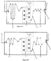
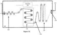
- Figures 3A - 3C illustrate embodiments of a curl resistant system 140.
- system 140 includes an input dancer rollers 305 and output dancer rollers 320 on either side of stationary drying rollers 310.
- dryer rollers transport web 120 through system 140 in a forward direction from the input to the output.
- rollers 305 move web 120 back and forth over to prevent a section of web 120 from being exposed to isolated heat and wrap angle, which could cause permanent curling of web 120 over dryer rollers 310.
- System 140 also includes a controller 300 to control various drying operations.
- Figure 3A illustrates one embodiment of system 140 during printing.
- web 120 is received at system 140 by travelling between a pinch roller 330 and a deflection roller 335, which provide stability as the web enters system 140.
- Pinch roller 330 may be in a fixed position or driven towards (or away from) deflection roller 335 by a positioning mechanism depending on the web handling needs.
- Deflection roller 335 may be either rotationally free spinning, braked or motor driven depending on the web handling needs.
- Ink applied to web 120 has dried to some extent prior to arriving at system 140.
- pinch roller 330 and deflection roller 335 enable web 120 to move during printing. Subsequently, web 120 passes through input dancer rollers 305 in a forward direction before being passed to drying rollers 310 by additional deflection rollers 335. In such an embodiment, dancer rollers 305 have minimal or no contact with web 120 during printing. Web 120 is received at dancer rollers 320 via deflection rollers after passing through drying rollers 310. In this embodiment, dancer rollers 320 are in a contact position with web 120 to provide tensioning and/or buffering for the web 120. An additional benefit is cooling of the web through contact with the dancing rollers or through airflow.
- Figure 3B illustrates one embodiment of system 140 once printing has stopped.
- pinch rollers 330 and deflection roller 335 at the input and output of system 140 are engaged to prevent portions of web 120 external to system 140 from moving.
- dancer rollers 305 engage, and pull, web 120 in a reverse direction from the output side through dryer rollers 310 to the input side.
- dancer rollers 320 retract to enable such movement.
- controller 300 provides a signal to pinch rollers 330 and dancer rollers 305 to initiate the above-described actions upon detecting that printing has stopped.
- controller 300 may pneumatically, or electromechanically control rollers 330, rollers 335 and rollers 305.
- Figure 3C illustrates one embodiment of system 140 once printing has stopped and dancer rollers 305 have been fully engaged.
- dancer rollers 305 are fully expanded to absorb all of web 120 from the output side, and dancer rollers 320 have minimal or no contact with web 120.
- controller 300 may control movement of each of dancer rollers 305 and/or 320 independently, as discussed in more detail below, to enable web 120 in a forward and backward direction while printing has stopped. The above-described embodiment prevents a given section of web 120 from being exposed to isolated heat and wrap angle since rollers 305 had minimal or no previous contact with web 120 prior to printing being stopped.
- output dancer rollers 320 may be solely implemented (e.g., no input dancer rollers or drying rollers).
- FIGS 4A and 4B illustrate another embodiment of a curl resistant system 140.
- dryer rollers include a large diameter roller 420 and dryer rollers 430.
- roller 420 is a stationary initial dryer roller to cure ink on a printed side of web 120 prior to the printed surface touching dryer rollers 430.
- Dryer rollers 430 are movable to automatically engage web 120 during printing and automatically disengage from web 120 when printing stops.
- Figure 4A illustrates one embodiment of system 140 in which dryer rollers 430 are in the engaged position during printing. Additionally, output side dancer rollers 320 have minimal or no engagement with web 120 during printing. However in other embodiments, rollers 320 may be engaged during printing to provide cooling, and later expand further to pick up web 120 from dryer rollers 430 upon disengagement.
- FIG. 4B illustrates one embodiment of system 140 in which dryer rollers 430 are disengaged when printing has stopped.
- dryer rollers 430 are moved to the disengaged position such that web 120 does not touch the stationary dryer roller 420 due to a deflection roller 450 being slightly higher in elevation.
- dancer rollers 320 are positioned further apart to pick up slack attributed to the disengaging of dryer rollers 430.
- dancer rollers 320 may be chilled to compensate for heat accumulated during the printing process in order to prevent paper curl/browning of web 120.
- dancer rollers 320, and dancer rollers 305 in Figures 3 may move independently for such prevention.
- Figures 5A - 5D illustrate embodiments of independent dancing rollers.
- Figure 5A represents an initial position of dancer rollers 320 during printing (or running mode operation).
- web 120 is traversing between points P1 and P2 in a web buffer (e.g., dancer accumulator or festoon accumulator).
- the web buffer facilitates web 120 movement between two web processing devices that may have different speeds, accelerations or pausing characteristics.
- dancer rollers 320 move position to maintain set web tension and also buffer a length of web.
- the amount of buffered web length (between P1 and P2) is increased or decreased as needed in order to maintain the set web tension.
- a force e.g., weight gravity, spring, pivot, pneumatic cylinder or other mechanism
- biased dancer rollers 320 will rise (e.g., in a direction opposite to the force on the biased dancer rollers).
- the biased dancer rollers will fall (e.g., in the direction of the force on the biased dancer rollers). If the biased rollers maintain their midpoint position, then the output and input web speeds of the buffer are equal. Typically, the biased rollers are fixed together and therefore move together, while the non-biased rollers are held in fixed position. In some embodiments, the force on the bias rollers in controlled by controller 300 for advanced dynamic control.
- controller 300 detects the start of the reduced curl mode (either from web sensor motion detection or by some other signal received by controller 300). Subsequently, controller 300 moves some dancer rollers 320 to different vertical positions such that the buffered web length is maintained and the desired web tension is maintained, which results in the web not traversing (as viewed from points P1 and P2). However, the roller-to-web contact locations are changing as the rollers move positions. In that sense, the buffered web is not traversing (in relation to P1 and P2) but the rollers are traversing the buffered web (in relation to P1 and P2).
- Figures 5B - 5D illustrate various embodiments of dancer roller re-positioned dancer rollers 320.
- roller positions In moving roller positions, the buffered web length and tension are maintained during the entire coordinated movement of the roller positions.
- actively controlled roller positioning is implemented electromechanically via controller 300.
- controller 300 commands new roller positions.
- input from roller position sensors, web tension sensors and other sensors can provide feedback for controller 300, which may implement PID feedback control to command the system.
- no rollers are biased with a force and all roller position movements are driven by the controller using sensor feedback.
- roller positions are moved vertically up and down resulting in the web moving forward and backward (back and forth) in relation to the rollers.
- roller positions may be continuously changed or incrementally changed at set time intervals.
- not all rollers need to move positions in order for the roller-to-web locations to change.
- a preferred embodiment includes non-biased rollers as the two end rollers and moving the position of at least those two rollers.
- the roller position may be restricted so as to not be moved beyond the web plane of adjacent rollers in order to properly maintain web tension (otherwise the web becomes un-engaged from one or more rollers).
- controller 300 may store initial roller positions at the start of the reduced curl mode and return the position driven rollers to the initial positions when the reduced curl mode is ending. Controller 300 is notified of the end of the reduced curl mode by detecting web movement outside of buffered web length. However in other embodiments, controller 300 may or receive an external signal, which results in controller 300 changing to the running mode (or some other mode).
- controller stops the roller position movement if a machine cover or guard sensors detect operator entry into the roller area in order to insure operator safety.
- system 140 doors can be locked to prevent the operator from opening the doors until the dryer rollers have cooled down to an acceptable temperature for the web to be stationary over the dryer rollers.
- FIGS 6A - 6D illustrate embodiments of deflection rollers.
- Figure 6A illustrates a non-changeable deflection roller 335 similar to those shown in Figures 3 and 4 .
- Figure 6B illustrates one embodiment of a pivot arm deflection roller 335 that rotates the arm upon changing from the running mode to the reduced curl mode. In this embodiment, the multiple rollers attached to the arms of roller 335 may then be selectively placed in contact with the web.
- Figure 6C illustrates one embodiment of a planetary roller wheel 335 that also rotates upon changing from the running mode to the reduced curl mode.
- Figure 6D illustrates one embodiment of an air bearing roller 335 in which web 120 does not make with the roller 335 due to a layer of air in between that is forced out of passages of 335.
- Dancer rollers 320, dancer rollers 305 and pinch rollers 330 may also use these deflection roller configurations.
Landscapes
- Engineering & Computer Science (AREA)
- Mechanical Engineering (AREA)
- General Engineering & Computer Science (AREA)
- Textile Engineering (AREA)
- Physics & Mathematics (AREA)
- General Physics & Mathematics (AREA)
- Life Sciences & Earth Sciences (AREA)
- Microbiology (AREA)
- Registering, Tensioning, Guiding Webs, And Rollers Therefor (AREA)
- Controlling Rewinding, Feeding, Winding, Or Abnormalities Of Webs (AREA)
- Handling Of Continuous Sheets Of Paper (AREA)
- Advancing Webs (AREA)
Claims (7)
- Bahnhandhabungssystem (140), umfassend:erste Tänzerwalzen (305), die gekoppelt sind, um mit einer Bahn (120) eines Druckmediums einzugreifen und diese in eine Vorwärts- und Rückwärtsrichtung nach Anhalten eines Druckvorgangs zu bewegen und eine Vorwärtsbewegung während des Druckvorgangs zuzulassen,Trockenwalzen (310; 430) zum Befördern der Bahn (120) eines Druckmediums in eine Vorwärtsrichtung während eines Druckvorgangs;zweite Tänzerwalzen (320) zum Befördern der Bahn eines Druckmediums in eine Vorwärtsrichtung während des Druckvorgangs;eine erste Andruckwalze (330) am Eingang des Bahnhandhabungssystems (140); undeine zweite Andruckwalze (330) am Ausgang des Bahnhandhabungssystems (140),dadurch gekennzeichnet, dassdie ersten Tänzerwalzen (305) konfiguriert sind, die Bahn (120) in umgekehrter Richtung nach Anhalten des Druckvorgangs zu ziehen und sich zu erweitern, um Abschnitte der Bahn (120) von den zweiten Tänzerwalzen (320) aufzunehmen,wobei die zweiten Tänzerwalzen (320) konfiguriert sind, sich einzuziehen, um mit der Bahn (120) in minimalem Kontakt zu sein, um zuzulassen, dass sich die Bahn (120) in die umgekehrte Richtung bewegt.
- System (140) nach Anspruch 1, wobei die ersten Tänzerwalzen (305) minimal in Kontakt mit der Bahn (120) während des Druckvorgangs sind.
- System (140) nach Anspruch 1, wobei die ersten und zweiten Andruckwalzen mit der Bahn (120) nach Anhalten des Druckvorgangs eingreifen, um zu verhindern, dass sich Abschnitte der Bahn (120) außerhalb des Bahnhandhabungssystems (140) bewegen.
- System (140) nach Anspruch 1, ferner umfassend eine Steuerung (300) zum Übertragen von Signalen an eine oder mehrere der ersten Tänzerwalzen (305), zweiten Tänzerwalzen (320) und der ersten und zweiten Andruckwalzen (330), um eine Angabe des Druckvorgangs bereitzustellen.
- System (140) nach Anspruch 4, wobei die Steuerung (300) die Signale an die eine oder die mehreren der ersten Tänzerwalzen (305) überträgt, um eine Spannung auf der Bahn (120) aufrechtzuhalten.
- System (140) nach Anspruch 1, ferner umfassend eine oder mehrere Umlenkwalzen (335).
- System (140) nach Anspruch 6, wobei die Umlenkwalzen eines aus einer Schwenkarmwalze, einem Planetenwalzenrad und einer Luftlagerwalze umfassen.
Applications Claiming Priority (1)
| Application Number | Priority Date | Filing Date | Title |
|---|---|---|---|
| US14/872,368 US10525735B2 (en) | 2015-10-01 | 2015-10-01 | Curl resistant web handling system |
Publications (3)
| Publication Number | Publication Date |
|---|---|
| EP3159173A2 EP3159173A2 (de) | 2017-04-26 |
| EP3159173A3 EP3159173A3 (de) | 2017-07-26 |
| EP3159173B1 true EP3159173B1 (de) | 2018-11-14 |
Family
ID=57003427
Family Applications (1)
| Application Number | Title | Priority Date | Filing Date |
|---|---|---|---|
| EP16190723.3A Active EP3159173B1 (de) | 2015-10-01 | 2016-09-27 | Kräuselungsresistentes bahnhandhabungssystem |
Country Status (3)
| Country | Link |
|---|---|
| US (3) | US10525735B2 (de) |
| EP (1) | EP3159173B1 (de) |
| JP (1) | JP6332380B2 (de) |
Families Citing this family (14)
| Publication number | Priority date | Publication date | Assignee | Title |
|---|---|---|---|---|
| US9605900B2 (en) * | 2015-04-22 | 2017-03-28 | Ricoh Company, Ltd. | Adjustable interlacing of drying rollers in a print system |
| US10227199B2 (en) * | 2016-11-02 | 2019-03-12 | Ricoh Company, Ltd. | Web handling roller wheel mechanism |
| JP7081182B2 (ja) * | 2018-02-01 | 2022-06-07 | セイコーエプソン株式会社 | 媒体供給装置 |
| CN109506441B (zh) * | 2018-11-13 | 2020-06-30 | 上海琪都纺织品有限公司 | 一种纺织布节能烘干机 |
| JP7237281B2 (ja) * | 2019-03-06 | 2023-03-13 | 住友ゴム工業株式会社 | ゴム被覆装置およびゴム被覆方法 |
| US11535045B2 (en) | 2019-03-06 | 2022-12-27 | Ricoh Company, Ltd. | Adjustable web handling mechanism |
| US11577870B1 (en) * | 2019-09-27 | 2023-02-14 | Amazon Technologies, Inc. | Isolated film tension and steering system |
| US11485597B2 (en) * | 2019-12-20 | 2022-11-01 | Ricoh Company, Ltd. | Dryer rollers of a print system with increasing contact area |
| CN111994692A (zh) * | 2020-09-25 | 2020-11-27 | 南京斯马特数码印务有限公司 | 数字印刷生产线用不停机纸张缓存系统 |
| DE102021112777A1 (de) * | 2021-05-18 | 2022-11-24 | Krones Aktiengesellschaft | Folienspeicher und Verfahren zum Speichern einer bandförmigen Endlosfolie |
| US11820124B2 (en) | 2021-08-18 | 2023-11-21 | Ricoh Company, Ltd. | Continuous-forms color measurement system |
| CN115615173B (zh) * | 2022-07-25 | 2023-10-13 | 南通雅顺莱纺织有限公司 | 一种用于针织品生产的烘干箱体 |
| JP7848637B2 (ja) * | 2022-08-30 | 2026-04-21 | 住友電気工業株式会社 | テープ供給装置、光ケーブル製造装置、及び光ケーブル製造方法 |
| CN116294481B (zh) * | 2023-03-13 | 2024-10-01 | 浙江金典印染有限公司 | 一种烘筒烘燥机及烘燥工艺 |
Family Cites Families (27)
| Publication number | Priority date | Publication date | Assignee | Title |
|---|---|---|---|---|
| JPH037366A (ja) | 1989-06-02 | 1991-01-14 | Fujitsu Ltd | プリンタ |
| FI91900C (fi) | 1990-12-17 | 1994-08-25 | Valmet Paper Machinery Inc | Menetelmä paperikoneen kuivatusosalla paperin käyristymistaipumuksen vähentämiseksi ja menetelmän toteuttamiseen tarkoitettu kuivatusosa |
| JPH07247045A (ja) | 1994-03-08 | 1995-09-26 | Hitachi Ltd | 記録装置 |
| JP2000007199A (ja) * | 1998-06-19 | 2000-01-11 | Ykk Corp | 長尺帯状物の処理装置 |
| US6203131B1 (en) * | 1998-07-28 | 2001-03-20 | Intermec Ip Corp. | Dual technology printer |
| US6669128B2 (en) * | 2001-07-06 | 2003-12-30 | Ksaria Corporation | Method and apparatus for automatically forming a coiled segment of optical fiber |
| US20030036249A1 (en) * | 2001-08-06 | 2003-02-20 | Bauer Donald G. | Chip alignment and placement apparatus for integrated circuit, MEMS, photonic or other devices |
| US6543201B2 (en) * | 2001-09-07 | 2003-04-08 | Automated Packaging Systems, Inc. | Individual package bagger and process |
| JP2004074642A (ja) | 2002-08-20 | 2004-03-11 | Komori Corp | 輪転印刷機 |
| JP2004155533A (ja) | 2002-11-05 | 2004-06-03 | Fuji Xerox Co Ltd | 連続紙搬送機構及びこれを有する印刷装置 |
| US8573481B1 (en) * | 2007-11-13 | 2013-11-05 | Diebold Self-Service Systems Division Of Diebold, Incorporated | Banking system controlled responsive to data bearing records |
| US20070289460A1 (en) | 2006-05-25 | 2007-12-20 | Michael Tang | Single pass plastic card manufacturing system |
| GB2464758B (en) | 2008-10-28 | 2012-11-07 | Inca Digital Printers Ltd | Substrate movement in a printer |
| US8249480B2 (en) | 2009-06-25 | 2012-08-21 | Eastman Kodak Company | Fusing apparatus for high speed electrophotography system |
| JP2011207054A (ja) | 2010-03-30 | 2011-10-20 | Seiren Co Ltd | インクジェットプリンタ |
| JP5043980B2 (ja) | 2010-04-22 | 2012-10-10 | キヤノン株式会社 | プリント装置 |
| JP5566792B2 (ja) * | 2010-06-25 | 2014-08-06 | 富士フイルム株式会社 | 画像記録方法および画像記録装置 |
| JP2012200875A (ja) * | 2011-03-23 | 2012-10-22 | Seiko Epson Corp | 画像形成装置及び画像形成方法 |
| US8721024B2 (en) * | 2012-06-06 | 2014-05-13 | Xerox Corporation | Inkjet printer having an image drum heater and cooler |
| US9067435B2 (en) | 2012-09-10 | 2015-06-30 | Electronics For Imaging, Inc. | Coupling of digital printer and finishing |
| US9039122B2 (en) | 2013-02-06 | 2015-05-26 | Ricoh Company, Ltd. | Controlled cooling of print media for a printing system |
| JP6254821B2 (ja) * | 2013-02-19 | 2017-12-27 | 株式会社リコー | 記録媒体加熱装置、及びそれを有するシステム |
| JP6048239B2 (ja) * | 2013-03-15 | 2016-12-21 | 株式会社リコー | 記録媒体加熱装置及び記録媒体加熱システム |
| JP2014188816A (ja) | 2013-03-27 | 2014-10-06 | Seiko Epson Corp | 記録装置 |
| JP2014219114A (ja) | 2013-05-01 | 2014-11-20 | キヤノン株式会社 | 乾燥装置および記録装置 |
| EP3074232B1 (de) | 2013-11-27 | 2018-01-03 | Sicpa Holding SA | Verfahren und vorrichtung zum bedrucken einer bahn |
| JP2015120268A (ja) * | 2013-12-20 | 2015-07-02 | 株式会社リコー | 処理液塗布装置及び画像形成システム |
-
2015
- 2015-10-01 US US14/872,368 patent/US10525735B2/en active Active
-
2016
- 2016-09-27 EP EP16190723.3A patent/EP3159173B1/de active Active
- 2016-09-27 JP JP2016188669A patent/JP6332380B2/ja active Active
-
2019
- 2019-11-18 US US16/686,902 patent/US10710380B2/en active Active
-
2020
- 2020-04-27 US US16/859,662 patent/US20200254787A1/en not_active Abandoned
Non-Patent Citations (1)
| Title |
|---|
| None * |
Also Published As
| Publication number | Publication date |
|---|---|
| EP3159173A2 (de) | 2017-04-26 |
| JP6332380B2 (ja) | 2018-05-30 |
| US10525735B2 (en) | 2020-01-07 |
| JP2017065926A (ja) | 2017-04-06 |
| US20170096017A1 (en) | 2017-04-06 |
| EP3159173A3 (de) | 2017-07-26 |
| US20200079116A1 (en) | 2020-03-12 |
| US20200254787A1 (en) | 2020-08-13 |
| US10710380B2 (en) | 2020-07-14 |
Similar Documents
| Publication | Publication Date | Title |
|---|---|---|
| EP3159173B1 (de) | Kräuselungsresistentes bahnhandhabungssystem | |
| US8459763B2 (en) | Image recording apparatus and image recording method | |
| EP2338816B1 (de) | Medieninversionssystem für einen Drucker mit kontinuierlichen Bahnen | |
| JP6314565B2 (ja) | 画像記録装置および画像記録方法 | |
| US20130127962A1 (en) | Image recording device, image recording method | |
| US20130321544A1 (en) | Vacuum pulldown of a print media in a printing system | |
| US9090424B1 (en) | Drive roller configuration providing reduced web wrinkling | |
| US10377128B2 (en) | Method for controlling a web in a printing apparatus | |
| US10201984B2 (en) | Printing system | |
| CN106976315B (zh) | 液滴喷出装置 | |
| JP2024088529A (ja) | 乾燥部を有する記録装置、および乾燥制御方法 | |
| JP6966908B2 (ja) | 印刷装置および印刷方法 | |
| JP7435259B2 (ja) | 乾燥装置及び液体吐出装置 | |
| US9205675B2 (en) | Device for drying a recording medium which is printed with ink in a printer, and method therefor | |
| US20140064817A1 (en) | Tension control in a web transport system | |
| US10227199B2 (en) | Web handling roller wheel mechanism | |
| US20150166290A1 (en) | Transport using peaked web guide and roller | |
| US20030146971A1 (en) | Color thermal printer and color thermal printing method | |
| JP7014238B2 (ja) | 調整可能なウェブハンドリング機構 | |
| US20140232776A1 (en) | Method for controlling tension in a web | |
| CN115243903A (zh) | 用于处理柔性幅材的系统和方法 | |
| CN221660405U (zh) | 介质输送装置以及印刷装置 | |
| JP2025079553A (ja) | 印刷装置及び印刷方法 | |
| JP2006044149A (ja) | インクジェット記録装置 |
Legal Events
| Date | Code | Title | Description |
|---|---|---|---|
| PUAI | Public reference made under article 153(3) epc to a published international application that has entered the european phase |
Free format text: ORIGINAL CODE: 0009012 |
|
| STAA | Information on the status of an ep patent application or granted ep patent |
Free format text: STATUS: REQUEST FOR EXAMINATION WAS MADE |
|
| 17P | Request for examination filed |
Effective date: 20160927 |
|
| AK | Designated contracting states |
Kind code of ref document: A2 Designated state(s): AL AT BE BG CH CY CZ DE DK EE ES FI FR GB GR HR HU IE IS IT LI LT LU LV MC MK MT NL NO PL PT RO RS SE SI SK SM TR |
|
| AX | Request for extension of the european patent |
Extension state: BA ME |
|
| PUAL | Search report despatched |
Free format text: ORIGINAL CODE: 0009013 |
|
| AK | Designated contracting states |
Kind code of ref document: A3 Designated state(s): AL AT BE BG CH CY CZ DE DK EE ES FI FR GB GR HR HU IE IS IT LI LT LU LV MC MK MT NL NO PL PT RO RS SE SI SK SM TR |
|
| AX | Request for extension of the european patent |
Extension state: BA ME |
|
| RIC1 | Information provided on ipc code assigned before grant |
Ipc: B41J 11/00 20060101AFI20170620BHEP Ipc: B65H 23/34 20060101ALI20170620BHEP Ipc: B41J 15/00 20060101ALI20170620BHEP Ipc: B65H 20/34 20060101ALI20170620BHEP |
|
| GRAP | Despatch of communication of intention to grant a patent |
Free format text: ORIGINAL CODE: EPIDOSNIGR1 |
|
| STAA | Information on the status of an ep patent application or granted ep patent |
Free format text: STATUS: GRANT OF PATENT IS INTENDED |
|
| INTG | Intention to grant announced |
Effective date: 20180531 |
|
| GRAS | Grant fee paid |
Free format text: ORIGINAL CODE: EPIDOSNIGR3 |
|
| GRAA | (expected) grant |
Free format text: ORIGINAL CODE: 0009210 |
|
| STAA | Information on the status of an ep patent application or granted ep patent |
Free format text: STATUS: THE PATENT HAS BEEN GRANTED |
|
| AK | Designated contracting states |
Kind code of ref document: B1 Designated state(s): AL AT BE BG CH CY CZ DE DK EE ES FI FR GB GR HR HU IE IS IT LI LT LU LV MC MK MT NL NO PL PT RO RS SE SI SK SM TR |
|
| REG | Reference to a national code |
Ref country code: CH Ref legal event code: EP Ref country code: AT Ref legal event code: REF Ref document number: 1064339 Country of ref document: AT Kind code of ref document: T Effective date: 20181115 |
|
| REG | Reference to a national code |
Ref country code: DE Ref legal event code: R096 Ref document number: 602016007140 Country of ref document: DE |
|
| REG | Reference to a national code |
Ref country code: IE Ref legal event code: FG4D |
|
| REG | Reference to a national code |
Ref country code: NL Ref legal event code: MP Effective date: 20181114 |
|
| REG | Reference to a national code |
Ref country code: LT Ref legal event code: MG4D |
|
| REG | Reference to a national code |
Ref country code: AT Ref legal event code: MK05 Ref document number: 1064339 Country of ref document: AT Kind code of ref document: T Effective date: 20181114 |
|
| PG25 | Lapsed in a contracting state [announced via postgrant information from national office to epo] |
Ref country code: FI Free format text: LAPSE BECAUSE OF FAILURE TO SUBMIT A TRANSLATION OF THE DESCRIPTION OR TO PAY THE FEE WITHIN THE PRESCRIBED TIME-LIMIT Effective date: 20181114 Ref country code: IS Free format text: LAPSE BECAUSE OF FAILURE TO SUBMIT A TRANSLATION OF THE DESCRIPTION OR TO PAY THE FEE WITHIN THE PRESCRIBED TIME-LIMIT Effective date: 20190314 Ref country code: NO Free format text: LAPSE BECAUSE OF FAILURE TO SUBMIT A TRANSLATION OF THE DESCRIPTION OR TO PAY THE FEE WITHIN THE PRESCRIBED TIME-LIMIT Effective date: 20190214 Ref country code: AT Free format text: LAPSE BECAUSE OF FAILURE TO SUBMIT A TRANSLATION OF THE DESCRIPTION OR TO PAY THE FEE WITHIN THE PRESCRIBED TIME-LIMIT Effective date: 20181114 Ref country code: LV Free format text: LAPSE BECAUSE OF FAILURE TO SUBMIT A TRANSLATION OF THE DESCRIPTION OR TO PAY THE FEE WITHIN THE PRESCRIBED TIME-LIMIT Effective date: 20181114 Ref country code: ES Free format text: LAPSE BECAUSE OF FAILURE TO SUBMIT A TRANSLATION OF THE DESCRIPTION OR TO PAY THE FEE WITHIN THE PRESCRIBED TIME-LIMIT Effective date: 20181114 Ref country code: LT Free format text: LAPSE BECAUSE OF FAILURE TO SUBMIT A TRANSLATION OF THE DESCRIPTION OR TO PAY THE FEE WITHIN THE PRESCRIBED TIME-LIMIT Effective date: 20181114 Ref country code: BG Free format text: LAPSE BECAUSE OF FAILURE TO SUBMIT A TRANSLATION OF THE DESCRIPTION OR TO PAY THE FEE WITHIN THE PRESCRIBED TIME-LIMIT Effective date: 20190214 Ref country code: HR Free format text: LAPSE BECAUSE OF FAILURE TO SUBMIT A TRANSLATION OF THE DESCRIPTION OR TO PAY THE FEE WITHIN THE PRESCRIBED TIME-LIMIT Effective date: 20181114 |
|
| PG25 | Lapsed in a contracting state [announced via postgrant information from national office to epo] |
Ref country code: PT Free format text: LAPSE BECAUSE OF FAILURE TO SUBMIT A TRANSLATION OF THE DESCRIPTION OR TO PAY THE FEE WITHIN THE PRESCRIBED TIME-LIMIT Effective date: 20190314 Ref country code: AL Free format text: LAPSE BECAUSE OF FAILURE TO SUBMIT A TRANSLATION OF THE DESCRIPTION OR TO PAY THE FEE WITHIN THE PRESCRIBED TIME-LIMIT Effective date: 20181114 Ref country code: SE Free format text: LAPSE BECAUSE OF FAILURE TO SUBMIT A TRANSLATION OF THE DESCRIPTION OR TO PAY THE FEE WITHIN THE PRESCRIBED TIME-LIMIT Effective date: 20181114 Ref country code: GR Free format text: LAPSE BECAUSE OF FAILURE TO SUBMIT A TRANSLATION OF THE DESCRIPTION OR TO PAY THE FEE WITHIN THE PRESCRIBED TIME-LIMIT Effective date: 20190215 Ref country code: RS Free format text: LAPSE BECAUSE OF FAILURE TO SUBMIT A TRANSLATION OF THE DESCRIPTION OR TO PAY THE FEE WITHIN THE PRESCRIBED TIME-LIMIT Effective date: 20181114 Ref country code: NL Free format text: LAPSE BECAUSE OF FAILURE TO SUBMIT A TRANSLATION OF THE DESCRIPTION OR TO PAY THE FEE WITHIN THE PRESCRIBED TIME-LIMIT Effective date: 20181114 |
|
| PG25 | Lapsed in a contracting state [announced via postgrant information from national office to epo] |
Ref country code: IT Free format text: LAPSE BECAUSE OF FAILURE TO SUBMIT A TRANSLATION OF THE DESCRIPTION OR TO PAY THE FEE WITHIN THE PRESCRIBED TIME-LIMIT Effective date: 20181114 Ref country code: CZ Free format text: LAPSE BECAUSE OF FAILURE TO SUBMIT A TRANSLATION OF THE DESCRIPTION OR TO PAY THE FEE WITHIN THE PRESCRIBED TIME-LIMIT Effective date: 20181114 Ref country code: PL Free format text: LAPSE BECAUSE OF FAILURE TO SUBMIT A TRANSLATION OF THE DESCRIPTION OR TO PAY THE FEE WITHIN THE PRESCRIBED TIME-LIMIT Effective date: 20181114 Ref country code: DK Free format text: LAPSE BECAUSE OF FAILURE TO SUBMIT A TRANSLATION OF THE DESCRIPTION OR TO PAY THE FEE WITHIN THE PRESCRIBED TIME-LIMIT Effective date: 20181114 |
|
| REG | Reference to a national code |
Ref country code: DE Ref legal event code: R097 Ref document number: 602016007140 Country of ref document: DE |
|
| PG25 | Lapsed in a contracting state [announced via postgrant information from national office to epo] |
Ref country code: EE Free format text: LAPSE BECAUSE OF FAILURE TO SUBMIT A TRANSLATION OF THE DESCRIPTION OR TO PAY THE FEE WITHIN THE PRESCRIBED TIME-LIMIT Effective date: 20181114 Ref country code: SM Free format text: LAPSE BECAUSE OF FAILURE TO SUBMIT A TRANSLATION OF THE DESCRIPTION OR TO PAY THE FEE WITHIN THE PRESCRIBED TIME-LIMIT Effective date: 20181114 Ref country code: RO Free format text: LAPSE BECAUSE OF FAILURE TO SUBMIT A TRANSLATION OF THE DESCRIPTION OR TO PAY THE FEE WITHIN THE PRESCRIBED TIME-LIMIT Effective date: 20181114 Ref country code: SK Free format text: LAPSE BECAUSE OF FAILURE TO SUBMIT A TRANSLATION OF THE DESCRIPTION OR TO PAY THE FEE WITHIN THE PRESCRIBED TIME-LIMIT Effective date: 20181114 |
|
| PLBE | No opposition filed within time limit |
Free format text: ORIGINAL CODE: 0009261 |
|
| STAA | Information on the status of an ep patent application or granted ep patent |
Free format text: STATUS: NO OPPOSITION FILED WITHIN TIME LIMIT |
|
| 26N | No opposition filed |
Effective date: 20190815 |
|
| PG25 | Lapsed in a contracting state [announced via postgrant information from national office to epo] |
Ref country code: SI Free format text: LAPSE BECAUSE OF FAILURE TO SUBMIT A TRANSLATION OF THE DESCRIPTION OR TO PAY THE FEE WITHIN THE PRESCRIBED TIME-LIMIT Effective date: 20181114 |
|
| PG25 | Lapsed in a contracting state [announced via postgrant information from national office to epo] |
Ref country code: TR Free format text: LAPSE BECAUSE OF FAILURE TO SUBMIT A TRANSLATION OF THE DESCRIPTION OR TO PAY THE FEE WITHIN THE PRESCRIBED TIME-LIMIT Effective date: 20181114 |
|
| PG25 | Lapsed in a contracting state [announced via postgrant information from national office to epo] |
Ref country code: MC Free format text: LAPSE BECAUSE OF FAILURE TO SUBMIT A TRANSLATION OF THE DESCRIPTION OR TO PAY THE FEE WITHIN THE PRESCRIBED TIME-LIMIT Effective date: 20181114 |
|
| REG | Reference to a national code |
Ref country code: CH Ref legal event code: PL |
|
| PG25 | Lapsed in a contracting state [announced via postgrant information from national office to epo] |
Ref country code: CH Free format text: LAPSE BECAUSE OF NON-PAYMENT OF DUE FEES Effective date: 20190930 Ref country code: LU Free format text: LAPSE BECAUSE OF NON-PAYMENT OF DUE FEES Effective date: 20190927 Ref country code: LI Free format text: LAPSE BECAUSE OF NON-PAYMENT OF DUE FEES Effective date: 20190930 Ref country code: IE Free format text: LAPSE BECAUSE OF NON-PAYMENT OF DUE FEES Effective date: 20190927 |
|
| REG | Reference to a national code |
Ref country code: BE Ref legal event code: MM Effective date: 20190930 |
|
| PG25 | Lapsed in a contracting state [announced via postgrant information from national office to epo] |
Ref country code: BE Free format text: LAPSE BECAUSE OF NON-PAYMENT OF DUE FEES Effective date: 20190930 |
|
| PG25 | Lapsed in a contracting state [announced via postgrant information from national office to epo] |
Ref country code: CY Free format text: LAPSE BECAUSE OF FAILURE TO SUBMIT A TRANSLATION OF THE DESCRIPTION OR TO PAY THE FEE WITHIN THE PRESCRIBED TIME-LIMIT Effective date: 20181114 |
|
| PG25 | Lapsed in a contracting state [announced via postgrant information from national office to epo] |
Ref country code: HU Free format text: LAPSE BECAUSE OF FAILURE TO SUBMIT A TRANSLATION OF THE DESCRIPTION OR TO PAY THE FEE WITHIN THE PRESCRIBED TIME-LIMIT; INVALID AB INITIO Effective date: 20160927 Ref country code: MT Free format text: LAPSE BECAUSE OF FAILURE TO SUBMIT A TRANSLATION OF THE DESCRIPTION OR TO PAY THE FEE WITHIN THE PRESCRIBED TIME-LIMIT Effective date: 20181114 |
|
| PG25 | Lapsed in a contracting state [announced via postgrant information from national office to epo] |
Ref country code: MK Free format text: LAPSE BECAUSE OF FAILURE TO SUBMIT A TRANSLATION OF THE DESCRIPTION OR TO PAY THE FEE WITHIN THE PRESCRIBED TIME-LIMIT Effective date: 20181114 |
|
| P01 | Opt-out of the competence of the unified patent court (upc) registered |
Effective date: 20230522 |
|
| PGFP | Annual fee paid to national office [announced via postgrant information from national office to epo] |
Ref country code: DE Payment date: 20250919 Year of fee payment: 10 |
|
| PGFP | Annual fee paid to national office [announced via postgrant information from national office to epo] |
Ref country code: GB Payment date: 20250919 Year of fee payment: 10 |
|
| PGFP | Annual fee paid to national office [announced via postgrant information from national office to epo] |
Ref country code: FR Payment date: 20250922 Year of fee payment: 10 |